External Field Response and Applications of Metal Coated Hemispherical Janus Particles

Department of Physics, Faculty of Science, Tokyo University of Science, 1-3 Kagurazaka, Shinjuku-ku, Tokyo 162-8601, Japan
*
Author to whom correspondence should be addressed.
Appl. Sci. 2018, 8(4), 653; https://0-doi-org.brum.beds.ac.uk/10.3390/app8040653
Submission received: 30 January 2018
/
Revised: 16 April 2018
/
Accepted: 16 April 2018
/
Published: 23 April 2018
(This article belongs to the Section Optics and Lasers)
Abstract
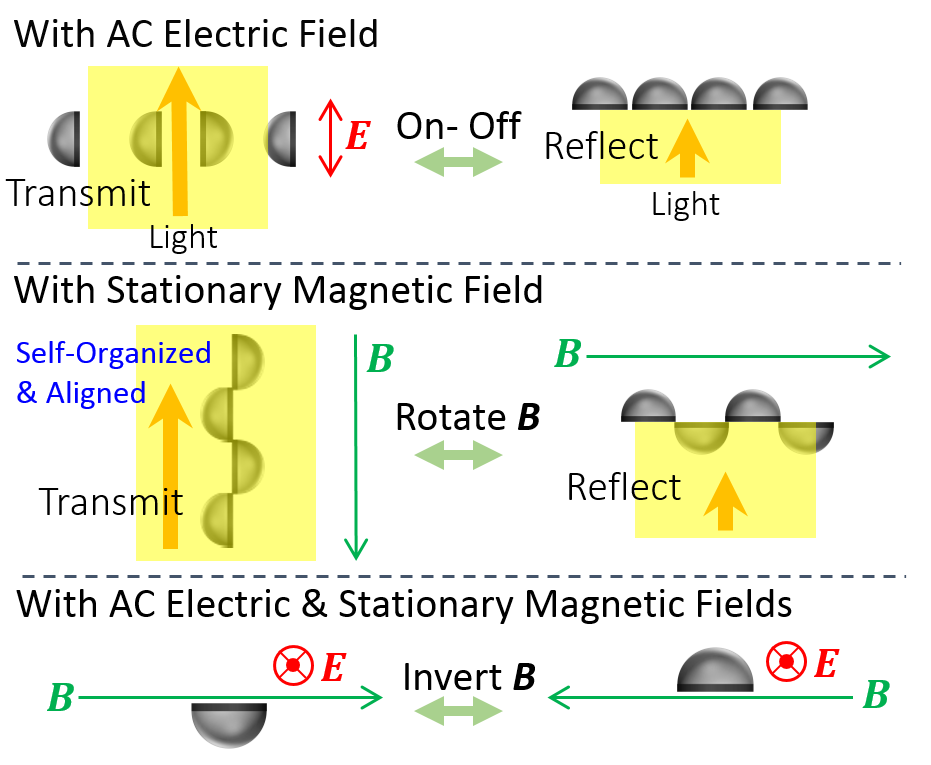
:Hemispherical Janus particles that were coated with silver or nickel on the equatorial plane of hemispherical polymer microparticles were prepared and dispersed in water and the responses to AC electric and stationary magnetic fields applied were investigated. Both of the particles are so oriented that the equatorial plane is parallel to the AC electric field, owing to electric-field induced dipole orientation, which is the response proportional to the quadratic electric field. The nickel coated particles are self-assembled to make a chain-like structure aligned in the direction of the stationary magnetic field. In addition, when both AC electric and stationary magnetic fields are applied, the orientation of a nickel-coated hemispherical particle is uniquely determined in such a way that the equatorial plane is parallel to both electric and magnetic fields. Because the particle is magnetized on the plane, its direction is reversed when the magnetic field is reversed, which is the response that is proportional to the magnetic field. Utilizing these features, mirrors are fabricated that can switch the transmittance and reflectance with electric and magnetic fields. Such features of the Janus particles as to be controlled by an electric and magnetic fields will find wide applications in the fields of microoptics and microfluidics.

1. Introduction
A Janus particle is a particle having surface and shape with two or more different physical and chemical properties [1]. “Janus” is named for the Roman god with two faces. As an essential feature of the Janus particle, anisotropy due to its asymmetric structure should be stressed. Because of this anisotropy, it possesses various physical and chemical functions. Janus particles are expected to be applied not only to basic science, such as biochemistry, physics, and colloid chemistry, but also to practical applications, such as drug delivery, electronic devices, optical biosensors, etc. Motility can be developed by giving driving force and controlling the orientation of particles. For example, the feature having self-propelled or external-field driven mobility [2,3,4,5,6] is expected to be applied to drug delivery. The feature that orientation is controllable can also be applied to display devices [7] such as electronic papers. Using the optically anisotropic particles that are fluorescent or transparent only on one side [8,9,10] as a probe, such applications are expected as tracers in microfluidics and optical biosensors for investigating rheology in living bodies.
A typical method for preparing simple Janus particles is to arrange silica or polystyrene particles, so as to form a single layer on a substrate, followed by the deposition of metal on only one side of the particles by vacuum evaporation [11]. Since such particles have anisotropic optical properties, interesting researches on the interaction of light with the particles have been reported. Firstly, researches on active matters have been intensively reported. By irradiating the laser light on the particle, it acts like a self-driven particle that is powered by the light energy [12]. Applications towards optical tweezers have also been reported, as follows. Rotating particles, like a light mill, are reported [13]. Particles are not only trapped by a laser, but also they move up and down along the temperature gradient induced by strong absorption due to localized plasmon of the metal [14]. In studies on surface plasmons, color can also be changed by attaching gold nanoparticles to one side of polystyrene particles [15].
Recently, hetero-shaped (heteromorphic) Janus particles are also drawing attention [16,17,18]. For example, tile-shaped metal/Si Janus particles (Janus tile) function as variable concave mirrors with uniform alignment at the liquid/liquid interface [16]. In this way, Janus particles different in shape from a sphere can be fabricated by etching or other methods, but in many cases it is necessary to use advanced technology and large-scale equipment. There are few reports that hetero-shaped particles are coated with metals partially at the specific site on the surface. This is because it is difficult to arrange the hetero-shaped particles by controlling their orientation in a single layer, whereas it is easy to arrange the spherically shaped particles. Heteromorphic microparticles compose a unique crystal structure for their optical properties to be investigated as new photonic crystals [19,20,21,22]. Some of them show electrophoresis [23]. The type of such functions and the magnitude of the response depend on the shape of the heteromorphic particle and its material distribution. Therefore, controlling the particle shape and the material distribution is important for developing the functional particles. Hemispherical particles, mushroom shaped particles, biconvex-lens shaped particles [24], dimple particles [25], snowman particles, raspberry particles [26], etc. have been so far fabricated. It is considered that further functions can be added and demonstrated if the heteromorphic particles that are thus produced can be site-selectively processed afterwards.
We successfully arranged the asymmetric hemispherical particles unidirectionally in two dimensions on the substrate and deposited metal only on the equatorial plane [27]. We named it a metal coated hemispherical Janus particle. This new Janus particle has a larger anisotropy in shape than the spherical Janus particle, with a prospect of exhibiting new functions.
It is reported that spherical Janus particles are self-assembled under an electric field [28]. Research that is focused on the property of active matter has been extensively performed [29,30], where the direction of movement is manipulated by further controlling the electric field [31]. It is interesting to study the behavior of metal coated hemispherical Janus particles under an electric field. We have investigated the response of the particles that are dispersed in water to an applied AC electric field. Experiments of applying not only an electric field, but also a magnetic field, are reported on Janus particles. The orientation of the particles is controlled [32] and interesting self-organizing behavior is observed [33,34,35], where ferromagnetic parts are connected like a chain. We have examined what kind of phenomenon occurs with ferromagnetic-metal coated hemispherical Janus particles, too.
In this paper, we report the optically interesting properties of the particles. Previously, we reported that surface plasmons can be excited in metallic coated hemispherical Janus particles. Here, we have found that the particle whose flat surface that is coated with metal can be utilized as a microscopic mirror. Further, the external field response of silver or nickel coated hemispherical Janus particles that are dispersed in water is investigated. When an AC electric field is applied, it is found that the equatorial metal surfaces of both silver and nickel coated particles are aligned parallel to the electric field. When a stationary magnetic field is applied, the nickel coated particles show self-assembled behavior to make a chain-form in the direction of the field. These properties can be utilized as a shutter. In addition, when the AC electric and stationary magnetic fields are simultaneously applied, the hemispherical particles can be uniquely oriented so that the equatorial plane is parallel to both electric and magnetic fields, and the direction of the particle is reversed when the magnetic field is reversed. As future prospects, the applicability to micro optical elements such as micromirrors and microfilters, and to valves and pumps in microfluidic channels is demonstrated.
2. Experiment
2.1. Sample Preparation
2.1.1. Unidirectional Arrangement of Hemispherical Particles
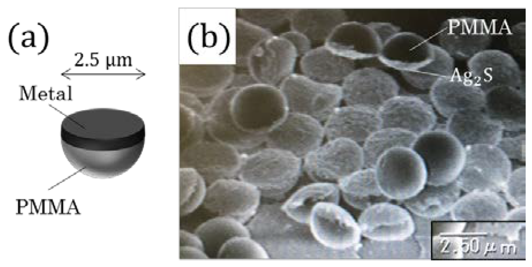
Hemispherical polymethylmethacrylate (PMMA) particles were provided by Sekisui Plastics Co., Ltd. (Tokyo, Japan). The material of these particles is cross-linked PMMA, and it does not dissolve in organic solvent. The particle diameter is 2.5 μm. The method for arranging particles is described in detail in [27]. Briefly, the hemispherical particles suspended in toluene were added in the water. It was sonicated to release aggregation of particles, and toluene and water were emulsified. After toluene was evaporated, the particles were arranged two-dimensionally at the air/water interface so that they were unidirectionally arranged. Then, they were transferred to a glass slide. Thus, hemispherical particles in the same direction were arranged two-dimensionally on a substrate. The degree of orientation is high, as demonstrated in Figure A1 in the Appendix A. By vacuum-depositing a metal on the hemispherical particles, Janus particles coated with metal only on the equatorial plane of hemispherical particles were prepared.
Figure 1 shows the scanning electron microscope (SEM) (VE-9800; Keyence, Osaka, Japan) image of hemispherical particles coated with a 50 nm silver film, where silver is sulfurized with a smoke solution. There is no structural change on the spherical surface, while the structure of the equatorial plane is changed due to the sulfurization to silver sulfide. This image confirms that the metals were deposited only on the equatorial plane of hemispherical particles.
2.1.2. Metal Coating on the Particles and Preparation of Suspensions of the Particles
For the reflectance measurement of a single Janus particles, silver of 100 nm thickness was vapor-deposited on the equatorial plane of hemispherical particles that were arranged on a cover glass at a pressure of 4.0 × 10⁻³ Pa and a deposition rate of 0.3 nm/s.
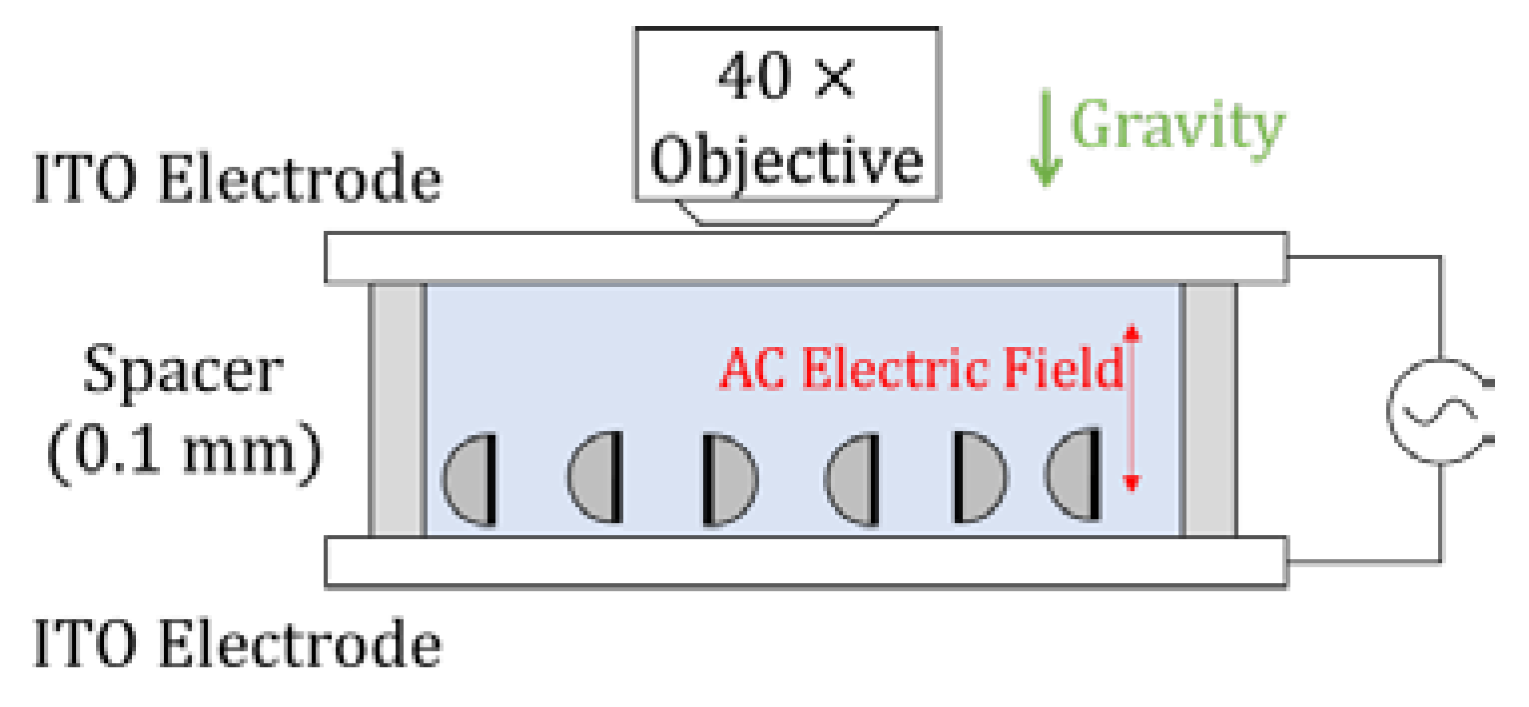
For the experiments of electric field application to a water suspension of particles, a 100 nm thick silver film was vacuum-deposited on the equatorial plane of the particles arranged on a glass slide at a pressure of 5.4 × 10⁻³ Pa and deposition rate of 0.3 nm/s. The film was sonicated in aqueous solution of 5% Pluronic F-127 (Anatrace, Maumee, OH, USA) for particles to disperse. The particles were centrifuged at 8000 rpm for 5 min, and the supernatant of the Pluronic F-127 solution was replaced with water. This operation is effective to prevent particles from sticking together [30]. The suspension of particles was sandwiched between Indium Tin Oxide (ITO) electrodes with a 0.1 mm spacer made of polypropylene.
For the experiments of magnetic field application, a 50 nm thick nickel film was vacuum that was deposited on the equatorial planes of hemispherical particles at 2.0 × 10⁻³ Pa and 0.3 nm/s. Care was required because nickel was readily to peel off the glass substrate. They were dispersed in water by sonication, dropped into a 6 mm diameter well surrounded by a 0.1 mm spacer on a glass slide, and were covered with a cover glass. Then, a ferrite magnet was brought closer from the side and the particles were observed with a microscope. The water suspension of particles was also placed in a 10 mm optical-path-length glass cell for the transmittance measurement.
2.2. Measurement Methods
2.2.1. Reflectance Measurement of Single Particles
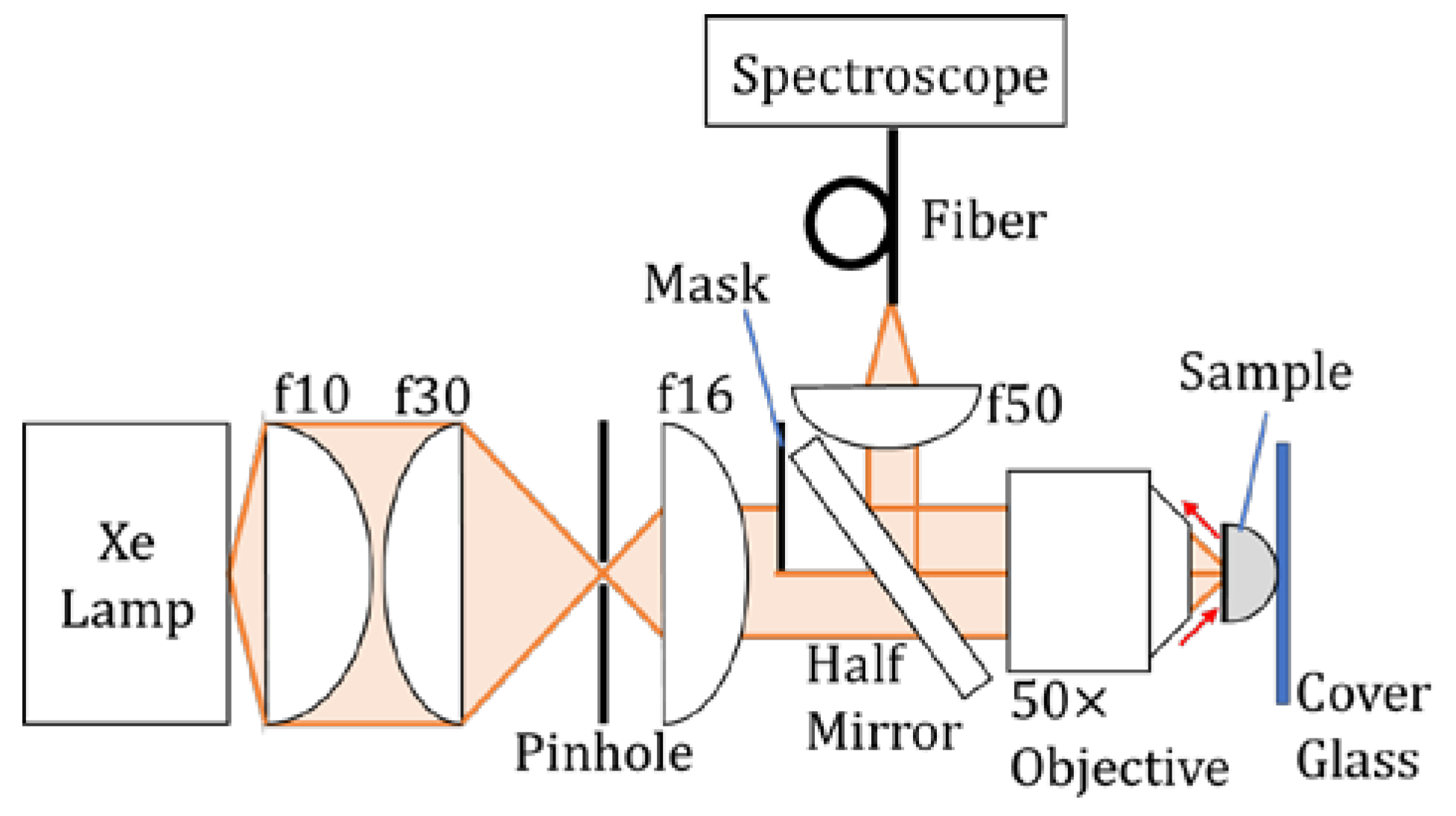
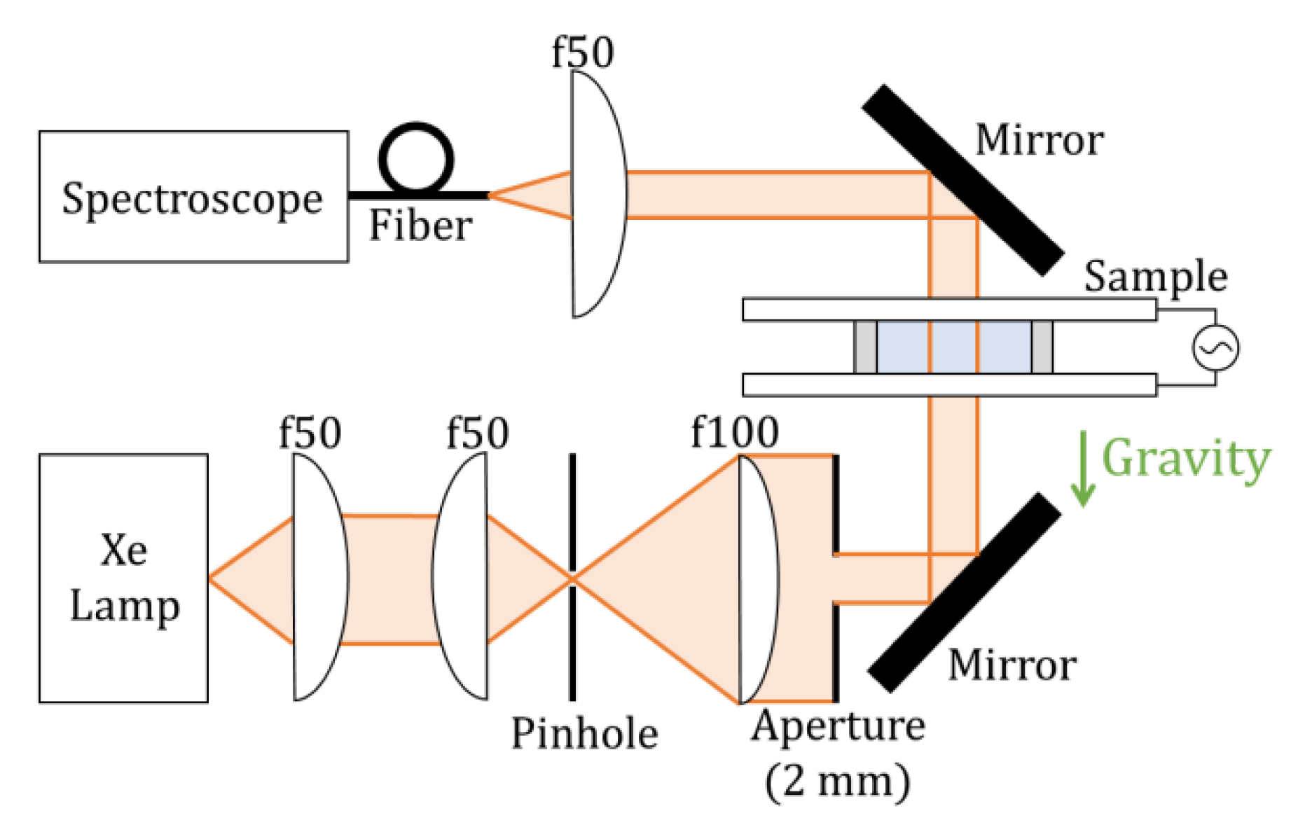
Metal-coated hemispherical Janus particles have a planar metal surface unlike spherical Janus particles with a hemispherical metal surface [9]. Therefore, the metal plane functions as a mirror that reflects light. The reflection spectra of respective Ag-coated Janus particles on the cover glass were measured by microspectroscopy. The optical system is shown in Figure 2. A xenon lamp (LDLS, ENERGETIQ, Woburn, MA, USA) was used as a light source. Collimated white light from the lamp was half masked, and then incident through a half mirror on an objective lens (50×, NA = 0.7, CFI L Plan EPI CR, Nikon, Tokyo, Japan) to be focused on the sample. The reflected light from the sample was collimated with the objective lens, reflected by the half mirror, collected with an achromatic lens of f = 50 mm, and incident on a spectrometer (USB 2000, Ocean Optics, Largo, FL, USA) through a fiber to obtain spectra. The light was incident on the sample from either the spherical or the equatorial-plane side. The reflection spectrum of the silver thin film on the substrate was also measured with the same optical system. The measurement wavelength range was from 400 to 800 nm. This is due to the limitations of the spectral band of the light source (Xe lamp), and the spectral sensitivity characteristics of the spectrometer and the silicon detector that was being used.
2.2.2. Transmission Measurement of the Suspensions with an Electric Field
An experimental setup is shown in Figure 3. After waiting for a minute, most of the Janus particles were precipitated on the bottom electrode. Then, an AC electric field with a frequency of 1 kHz and a voltage of 10 V was applied to the suspension. The behavior of particles was observed with an objective lens (40×, LUCPLFLN-RC, OLYMPUS, Tokyo, Japan). Then, the transmittance spectra were measured before and after the electric field was applied. The optical system is shown in Figure 4. Collimated light with a diameter of 2 mm was irradiated from directly below the sample. The electric field was applied under the same experimental conditions as above. The measured wavelength range was 400–800 nm.
2.2.3. Transmission Measurement of the Suspensions with a Magnetic Field
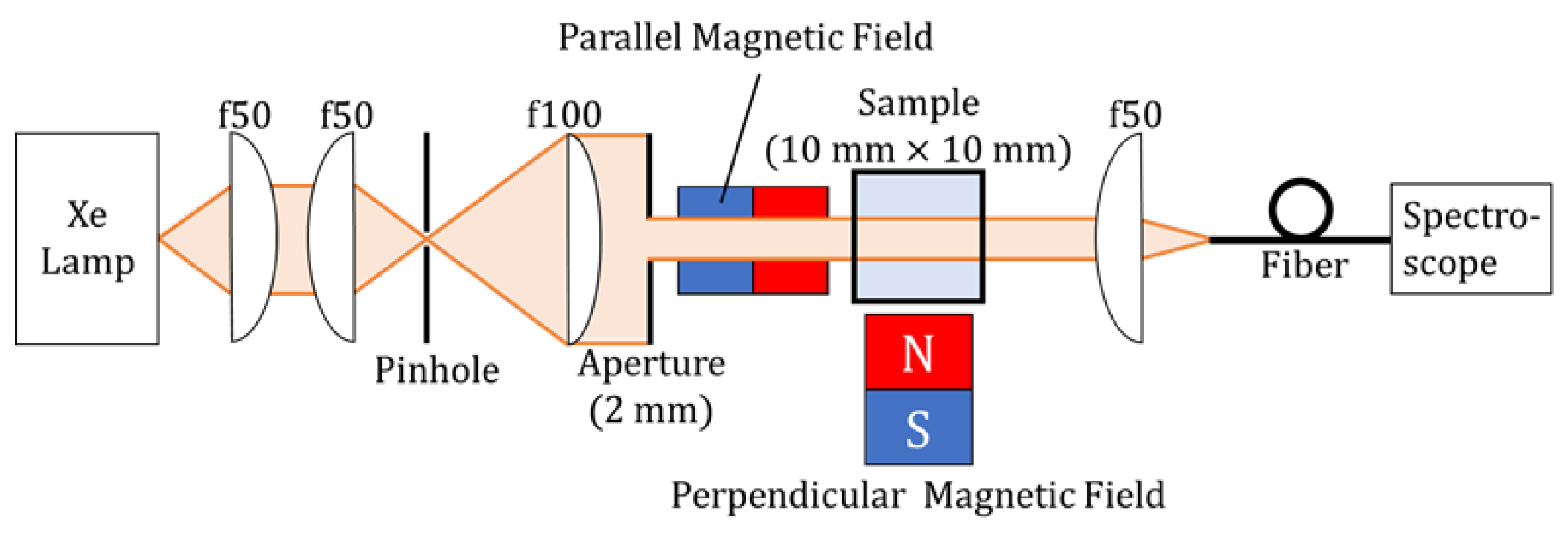
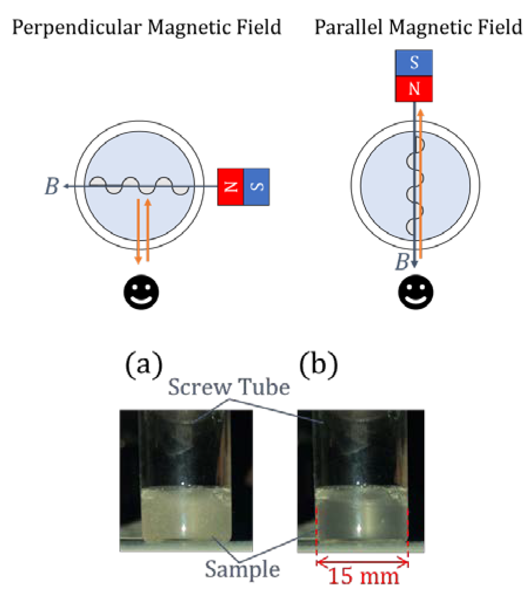
The optical system is shown in Figure 5. A magnetic field was applied either parallel or perpendicular to the wavevector of the incident light. When applying a magnetic field that was parallel to the light propagation direction, the magnet was brought closer from obliquely below to avoid the light being blocked by the magnet. To avoid the particles from being too strongly attracted to the magnets for their distribution to be severely distorted in the suspension, a strong magnet such as a neodymium magnet was not used but a relatively weak ferrite magnet was used.
An electric field was also applied to the particles that were deposited with nickel in the same experimental condition, as in the case of those that were deposited with silver. After that, the behavior was observed when the ferrite magnet was brought closer from the side.
3. Results and Discussion
3.1. Reflectance Measurement of Single Particles
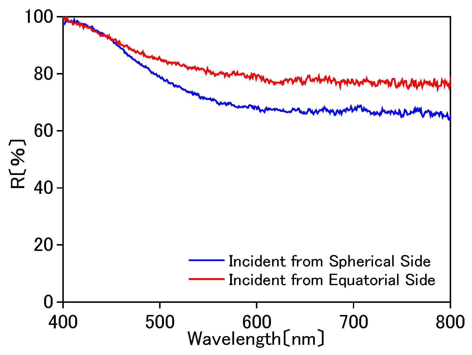
R is defined as R = (reflected intensity from a silver coated hemispherical Janus particle)/(reflected intensity from a silver thin film on the cover glass). In this way, the relative reflectance with respect to the silver thin film was determined. The results in the experimental setup in Figure 2 are shown in Figure 6. The relative reflectance of the equatorial plane was roughly 80%, demonstrating that it sufficiently functions as a mirror. When the focused light was incident on the spherical surface, the reflectance was decreased as compared to the incidence on the equatorial plane. This is because the light is reflected on a hemispherical surface when it enters and leaves the particle. The reflected light reaches the detector only when the following conditions hold with high precision. That is, the surface of the particle is perfectly spherical, the silver thin film is coated on the exact equatorial plane of the sphere, and the focal point of the focused light coincides with the center of the sphere. It was difficult for this optical system to satisfy all of these requirements. Since the refractive index of PMMA is 1.49, the reflectance is 3.9%. Therefore, when incident on the spherical surface, the light to be detected is decreased to 92% due to this reflection, when compared with the light incident on the equatorial plane. Surface plasmon resonance was not observed when light was incident from the spherical side. This is because unpolarized white light was incident, the film thickness of 100 nm was too thick, and the numerical aperture (NA) of the objective lens was 0.7. Due to the low NA, the angle of incidence was too small for most of light to satisfy the total reflection condition that was needed for the resonance. In fact, the resonance was observed on the condition of 50 nm and NA = 1.49 when p-polarized light was incident [27].
3.2. Transmission and Reflection Measurement with an Electric Field
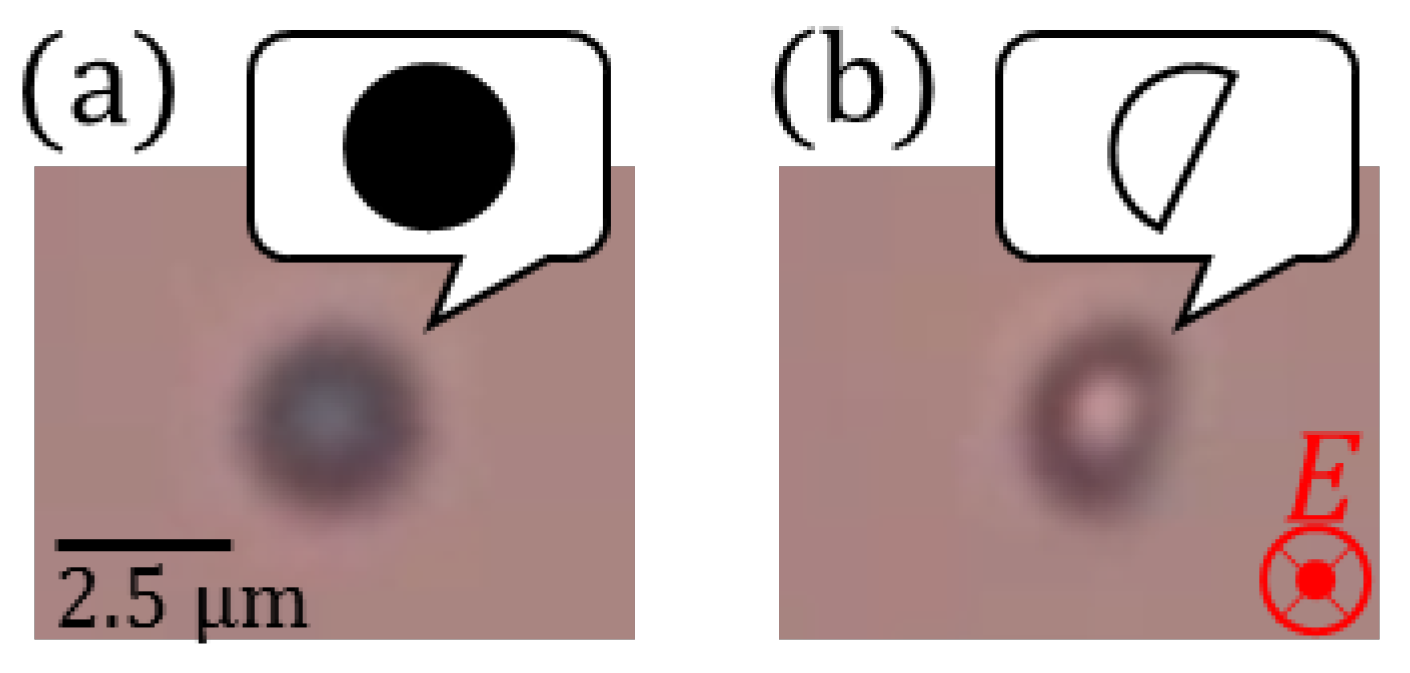
The results of application of an AC electric field to the silver coated particles are shown in Figure 7. It turned out that the metal surface was oriented parallel to the field, which was kept while the field was on. This is because the electric-field induced electric dipole moment is maximally aligned in the direction of the electric field.
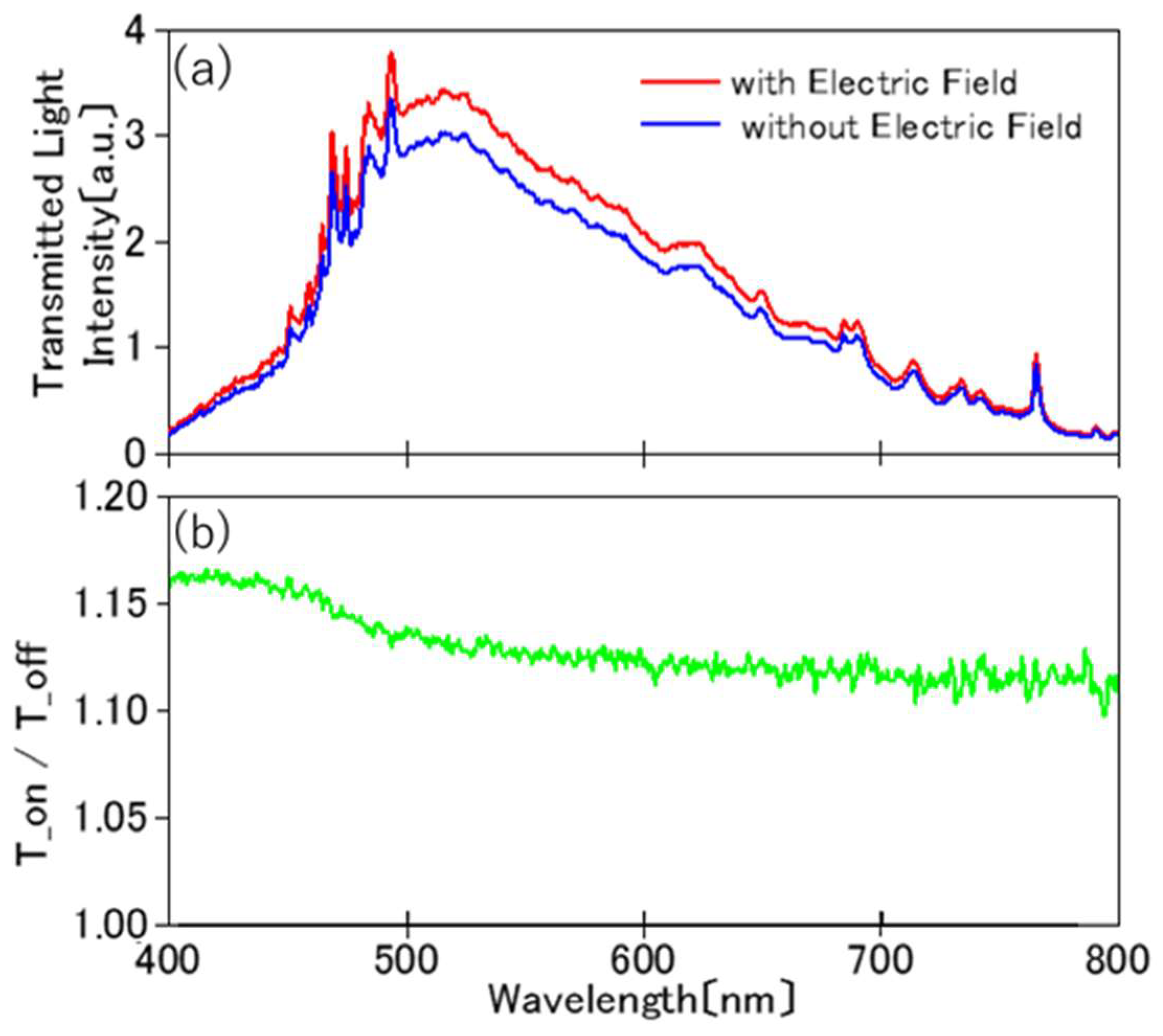
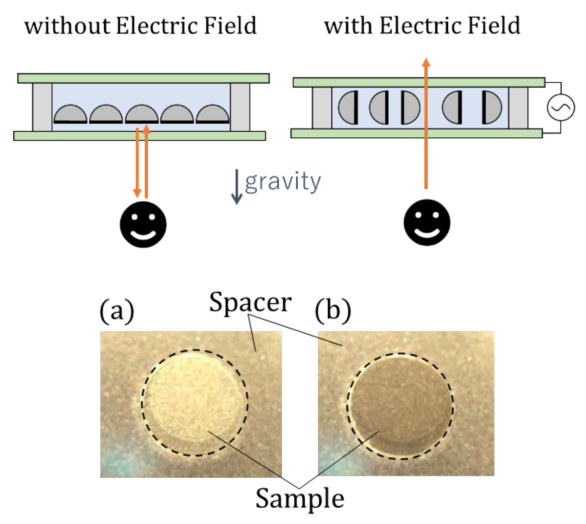
The transmittance of the suspension before and after the electric field was applied is shown in Figure 8. When the electric field was applied, the transmitted light intensity increased by 10 to 15 percent. This is explained as follows. Without an electric field, metal coated hemispherical Janus particles in water are stabilized in such a way that the metal surface is perpendicular to the direction of gravity. Therefore, the light that is passing perpendicularly to the ITO electrode is blocked by the metal surface. With the electric field that is applied, the metal surface becomes parallel to the field. Then, light passing perpendicularly to the ITO electrode does not hit the metal surface, but is transmitted. In other words, it functions as an electric-field controlled shutter, in such a way that it blocks and passes light without and with the electric field, respectively.
From the number density of the particles that were estimated from the microscope image, the coverage of the particles was 15.7% of the transmission area if the cross section of all the particles is assumed to be a circle with a diameter of 2.5 μm. When the electric field is applied, the cross-section turns to a semicircle for the effective coverage to be 0% (if the light is perfectly transmitted through the transparent semicircle) to 8% (the light is completely deflected by the transparent semicircle, which is actually the transparent hemisphere, due to refraction etc.), which is in reasonable agreement with the observed increase in the transmittance by 10–15%. Therefore, if the number density of particles is increased, the function as a shutter will be more enhanced. This effect is clearly seen in the photograph in Figure 9, where a reflection and transmission switch is demonstrated with the bulk suspension.
3.3. Transmission and Reflection Measurement with a Magnetic Field
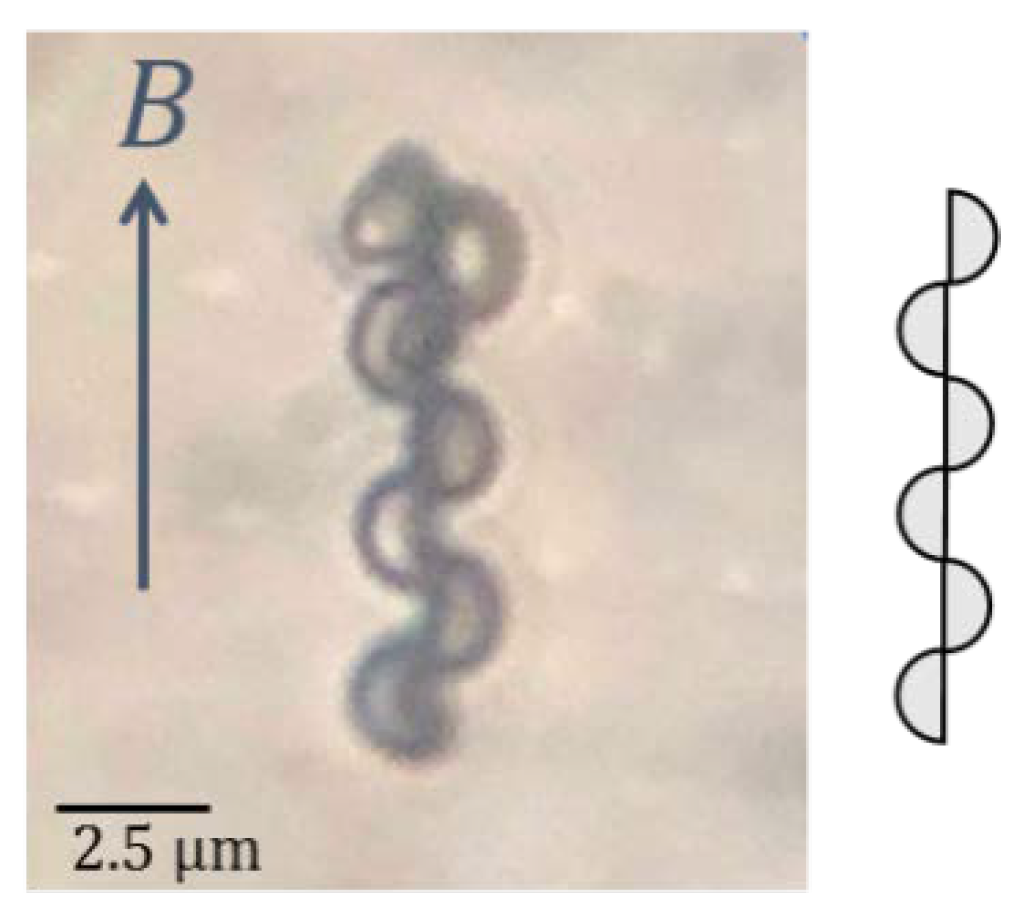
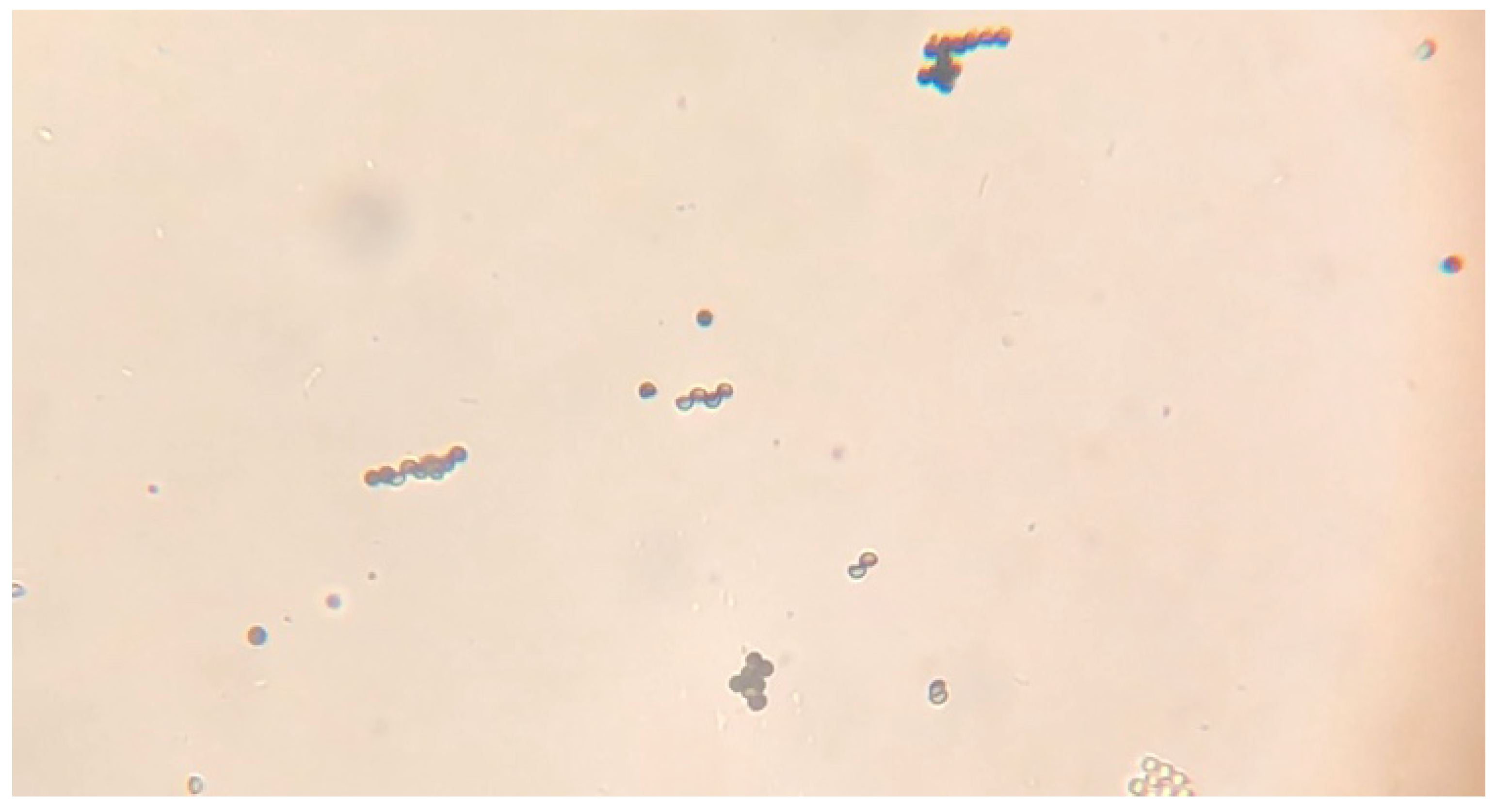
When the nickel coated hemispherical Janus particles are dispersed in water, the nickel surface faces downward due to gravity. Then, a magnetic field is applied from the side; with the result that each particle is magnetized for the particles attract each other to be self-organized. With a microscope, an ordered assembly like a chain was often found under the magnetic field, as shown in Figure 10. Similar chain formation with magnetic Janus particles has been described before [33,34,35]. Once magnetized, the particles tend to be self-assembled even without the magnetic field, but not in order. Before the light transmission experiment below, therefore, a stationary magnetic field was applied for nearly 10 min. Then, most of the particles were prompted to be self-assembled in an ordered structure like a chain, as shown in Figure A2.
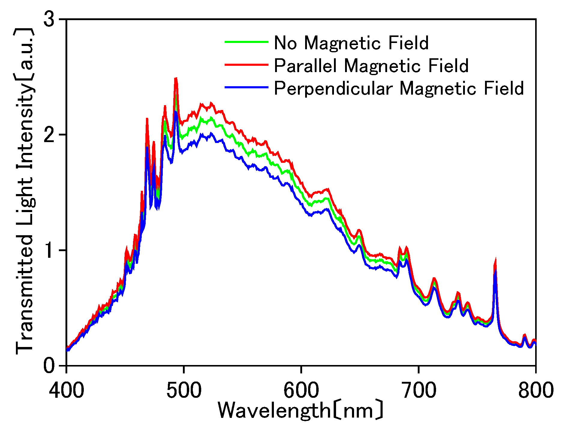
The results of the transmitted light intensity are shown in Figure 11. The transmitted light intensity was decreased as the magnetic field was oriented perpendicular to the light propagation direction, while it was increased as the magnetic field was oriented parallel to the light direction. Suppose that the light passes through the suspension of the self-organized particles like a chain. The light passing perpendicularly to the chain is blocked and the light passing parallel to the chain is transmitted. Such a phenomenon occurs because the direction of the chain is controlled by the magnetic field. This effect is clearly seen as a reflection and transmission switch with the bulk suspension, as shown in Figure 12.
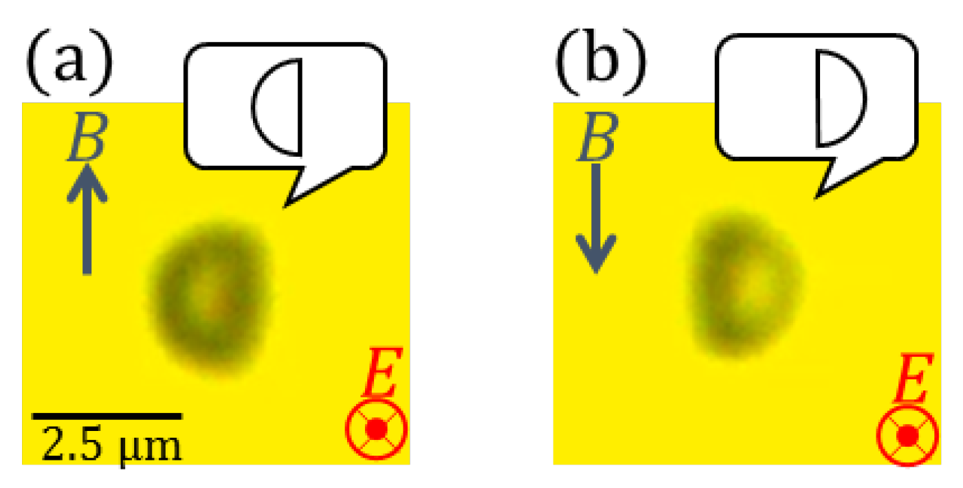
When an AC electric field was applied, the metal surfaces of nickel-coated particles were made parallel to the field, as well as silver-coated ones. Then, as the ferrite magnet was brought closer from the side, a particle was oriented in such a way that the equatorial plane was parallel to the stationary magnetic field. In addition, when the direction of the magnetic field was reversed, the direction of the metal surface was reversed. The results are shown in Figure 13. Note that a highly controllable manipulation of the particle orientation was realized by applying both the electric and magnetic fields. The electric field defines the axis in the direction parallel to the electric field on the metal surface. Furthermore, the direction can be controlled by rotating around its axis by a magnetic field.
Further, it turned out that the particle was rotated when the magnetic field was quickly rotated. It is very important to control the direction of the metal surface in this way when such applications as micromirrors, microshutters, etc. are considered. A micromirror with good controllability can be readily produced by depositing a highly reflective metal on ferromagnetic material that is deposited on the particles. It can also be applied as a minute variable color filter. Surface plasmons can be excited on metal coated hemispherical Janus particles [27], so that the spectrum of the reflected light is varied depending on the incidence angle, because the resonance wavelength is sensitive to the angle [36]. From the fact that the direction of the particles can be precisely controlled by the electric and magnetic fields, as demonstrated here, light can be made incident on the particle at an arbitrary incident angle for the spectrum of the reflected light to be varied. Since the particle can be rotated, it can also be used for the microchannel devices, such as valves and pumps.
4. Conclusions and Prospects
We reported the various properties of metal coated hemispherical Janus particles from the application point of view. First of all, it was demonstrated that the particle has a property of mirror because the metal surface is flat. It was found that the orientation of the particles can be controlled by electric and magnetic fields. Controlling the orientation of the particle is very important in their applications to microoptics and microfluidics. From these characteristics, we demonstrated the function as optical shutters. They are also usable for micromirrors and micro variable color filters. Demands for micrometer-sized mirrors and their angle control is wide for the use in digital micromirror devices [37], displays, projectors, etc. They are also suited for valves in micro fluidic channels because they can be operated readily in a narrow space [38]. They can also be used as minute pumps, which cannot be done with spherical Janus particles, but takes the most advantage of the hemispherical shape. There should also be demands in medical fields. A micro-mirror device is also used as medical equipment for laser treatment [39]. To perform minimally invasive treatment, it is promising to reduce the size of each instrument while using the metal coated hemispherical Janus particles. It is expected that one can find many other applications utilizing the properties that the particles can be orientationally controlled. The fact that the particles are hemispherical and that they can be coated with a functional material on one side is of great advantage for the applicability to be unbounded.
Supplementary Materials
The following are available online at https://0-www-mdpi-com.brum.beds.ac.uk/2076-3417/8/4/653/s1, Video S1: Response of an Ag-coated particle when an AC electric field is switched on, Video S2: Reflection change of the ITO-sandwiched suspension of Ag-coated particles with an AC electric field on, Video S3: Reflection change of the suspension of Ni-coated particles assembled in a chain-like form when the magnetic field direction is changed from perpendicular to parallel with respect to the light propagation direction.
Acknowledgments
The authors would like to thank Masafumi Hashimoto and Yusuke Nishiyama for counting the number of the particles. Hemispherical particles are provided by Ryosuke Harada, Sekisui Plastic Co., Ltd., Nishi Tenman 2-4-4, Kita-ku, Osakashi, Osaka, Japan.
Author Contributions
E.T. and S.A. conceived and designed the experiments; S.A. prepared samples and performed the experiments; K.S. contributed sample preparation; S.A. and E.T. wrote the paper.
Conflicts of Interest
The authors declare no conflict of interest.
Appendix A
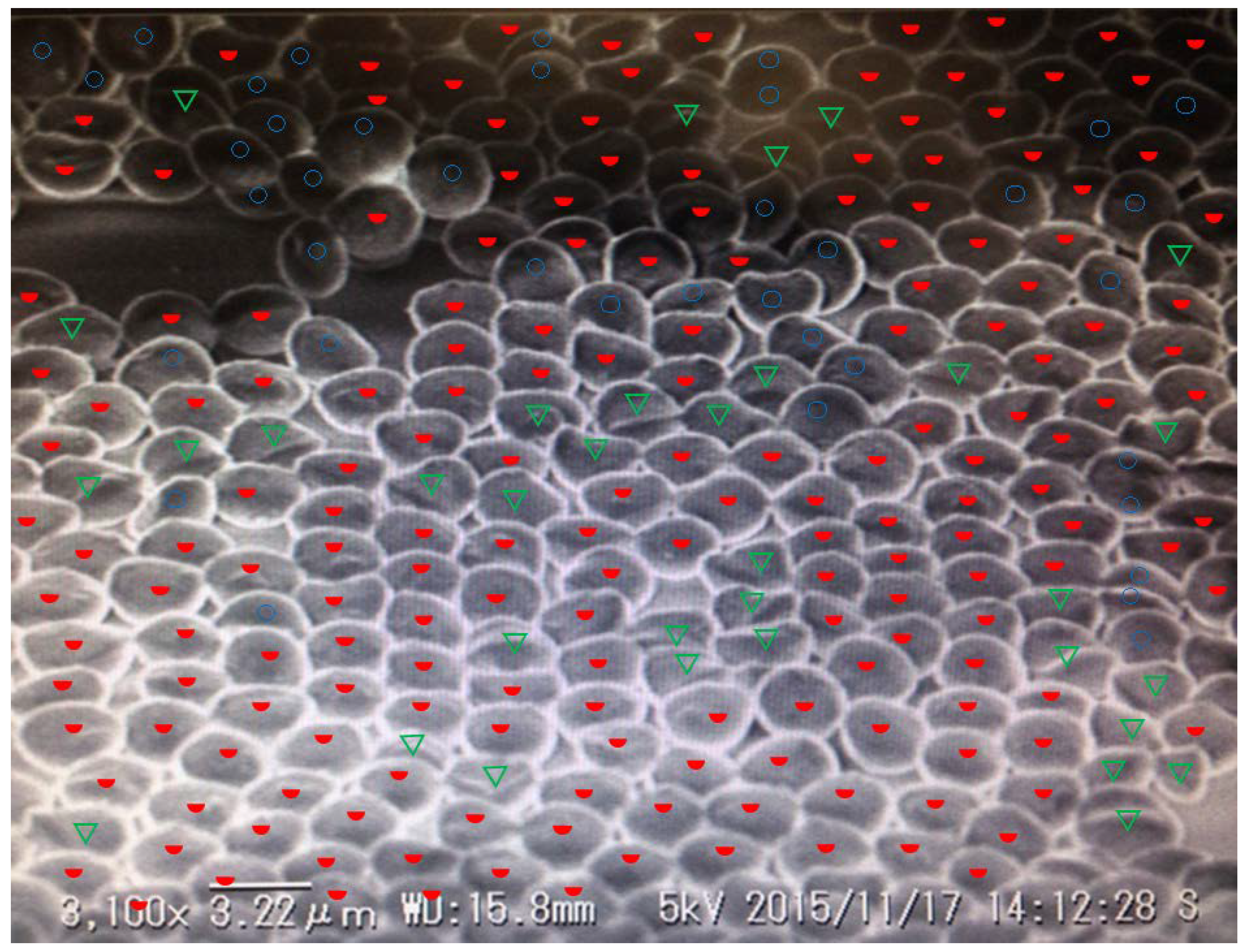
We surveyed the degree of orientation for a typical SEM image of particles arranged on the glass substrate as shown in Figure A1. The results are summarized as follows. The ratio of the particles with the equatorial plane upwards is 83.1% among the hemispherical particles and 72.8% among all the particles.
Figure A1.
Typical SEM image of particles arranged on a glass slide. The particles marked by the red semicircle (193 particles) are well oriented with the equatorial plane upwards. Those marked by the blue circle (39 particles) are not well oriented or accumulated with the equatorial plane not facing upward. The particles marked by the green triangle (33 particles) do not have a semi-spherical shape. (Referred in Section 2.1.1).

Figure A2.
Microscope photograph of Ni-coated hemispherical Janus particles in water after a magnetic field was applied for a long time. (Referred in Section 3.3).
Figure A2.
Microscope photograph of Ni-coated hemispherical Janus particles in water after a magnetic field was applied for a long time. (Referred in Section 3.3).

References
- Casagrande, C.; Fabre, P.; Raphael, E.; Veyssie, M. “Janus Beads”: Realization and Behaviour at Water/Oil Interfaces. Europhys. Lett. 1989, 9, 251–255. [Google Scholar] [CrossRef]
- Walther, A.; Muller, A.H.E. Janus particles. Soft Matter 2008, 4, 663–668. [Google Scholar] [CrossRef]
- Sundararajan, S.; Lammert, P.E.; Zudans, A.W.; Crespi, V.H.; Sen, A. Catalytic Motors for Transport of Colloidal Cargo. Nano Lett. 2008, 8, 1271–1276. [Google Scholar] [CrossRef] [PubMed]
- Wang, J. Can Man-Made Nanomachines Compete with Nature Biomotors? ACS Nano 2009, 3, 4–9. [Google Scholar] [CrossRef] [PubMed]
- Palacci, J.; Sacanna, S.; Steinberg, A.P.; Pine, D.J.; Chaikin, P.M. Living crystals of light-activated colloidal surfers. Science 2013, 339, 936–940. [Google Scholar] [CrossRef] [PubMed]
- Dietrich, K.; Renggli, D.; Zanini, M.; Volpe, G.; Buttinoni, I.; Isa, L. Two-dimensional nature of the active Brownian motion of catalytic microswimmers at solid and liquid interfaces. New J. Phys. 2017, 19, 065008. [Google Scholar] [CrossRef]
- Nisisako, T.; Torii, T.; Takahashi, T.; Takizawa, Y. Synthesis of Monodisperse Bicolored Janus Particles with Electrical Anisotropy Using a Microfluidic Co-Flow System. Adv. Mater. 2006, 18, 1152–1156. [Google Scholar] [CrossRef]
- Behrend, C.J.; Anker, J.N.; McNaughton, B.H.; Brasuel, M.; Philbert, M.A.; Kopelman, R. Metal-Capped Brownian and Magnetically Modulated Optical Nanoprobes (MOONs): Micromechanics in Chemical and Biological Microenvironments. J. Phys. Chem. B. 2004, 108, 10408–10414. [Google Scholar] [CrossRef]
- Behrend, C.J.; Anker, J.N.; Kopelman, R. Brownian modulated optical nanoprobes. Appl. Phys. Lett. 2004, 84, 154–156. [Google Scholar] [CrossRef]
- Anker, J.N.; Behrend, C.J.; Kopelman, R. Aspherical magnetically modulated optical nanoprobes (MagMOONs). J. Appl. Phys. 2003, 93, 6698–6700. [Google Scholar] [CrossRef]
- Takei, H.; Shimizu, N. Gradient Sensitive Microscopic Probes Prepared by Gold Evaporation and Chemisorption on Latex Spheres. Langmuir 1997, 13, 1865–1868. [Google Scholar] [CrossRef]
- Jiang, H.R.; Yoshinaga, N.; Sano, M. Active Motion of a Janus Particle by Self-Thermophoresis in a Defocused Laser Beam. Phys. Rev. Lett. 2010, 105, 268302. [Google Scholar] [CrossRef] [PubMed]
- Merkt, F.S.; Erbe, A.; Leiderer, P. Capped colloids as light-mills in optical traps. New J. Phys. 2006, 8, 216. [Google Scholar] [CrossRef]
- Nedev, S.; Carretero-Palacios, S.; Kühler, P.; Lohmüller, T.; Urban, A.S.; Anderson, L.J.E.; Feldmann, J. An Optically Controlled Microscale Elevator Using Plasmonic Janus Particles. ACS Photonics 2015, 2, 491–496. [Google Scholar] [CrossRef] [PubMed]
- Suzuki, D.; Kawaguchi, H. Janus particles with a functional gold surface for control of surface plasmon resonance. Colloid Polym. Sci. 2006, 284, 1471–1476. [Google Scholar] [CrossRef]
- Bucaro, M.A.; Kolodner, P.R.; Taylor, J.A.; Sidorenko, A.; Aizenberg, A.; Krupenkin, T.N. Tunable Liquid Optics: Electrowetting-Controlled Liquid Mirrors Based on Self-Assembled Janus Tiles. Langmuir 2009, 25, 3876–3879. [Google Scholar] [CrossRef] [PubMed]
- Bradley, L.C.; Stebe, K.J.; Lee, D. Clickable Janus Particles. J. Am. Chem. Soc. 2016, 138, 11437–11440. [Google Scholar] [CrossRef] [PubMed]
- Zhao, H.; Liang, F.; Qu, X.; Wang, Q.; Yang, Z. Conelike Janus Composite Particles. Macromolecules 2015, 48, 700–706. [Google Scholar] [CrossRef]
- Lu, Y.; Yin, Y.; Xia, Y. Three-Dimensional Photonic Crystals with Non-spherical Colloids as Building Blocks. Adv. Mater. 2001, 13, 415–420. [Google Scholar] [CrossRef]
- Mock, E.B.; Zukoski, C.F. Determination of static microstructure of dilute and concentrated suspensions of anisotropic particles by ultra-small-angle X-ray scattering. Langmuir 2007, 23, 8760–8771. [Google Scholar] [CrossRef] [PubMed]
- Hosein, I.D.; Liddell, C.M. Convectively assembled nonspherical mushroom cap-based colloidal crystals. Langmuir 2007, 23, 8810–8814. [Google Scholar] [CrossRef] [PubMed]
- Hosein, I.D.; Liddell, C.M. Convectively Assembled Asymmetric Dimer-Based Colloidal Crystals. Langmuir 2007, 23, 10479–10485. [Google Scholar] [CrossRef] [PubMed]
- Ho, C.C.; Ottewill, R.H.; Yu, L. Examination of Ellipsoidal Polystyrene Particles by Electrophoresis. Langmuir 1997, 13, 1925–1930. [Google Scholar] [CrossRef]
- Harada, R. Irregularly Shaped Particles and Method for Producing Same. Patent WO2010113812A1, 7 October 2010. [Google Scholar]
- Higuchi, T.; Yabu, H.; Shimomura, M. Simple preparation of hemispherical polystyrene particles. Colloids Surf. A. 2006, 284, 250–253. [Google Scholar] [CrossRef]
- Perro, A.; Reculusa, S.; Bourgeat-Lami, E.; Duguet, E.; Ravaine, S. Synthesis of hybrid colloidal particles: From snowman-like to raspberry-like morphologies. Colloids Surf. A Physicochem. Eng. Asp. 2006, 284–285, 78–83. [Google Scholar]
- Aizawa, S.; Seto, K.; Tokunaga, E. Orientation Control of Hemispherical Janus Particles and Metal Coating on the Selective Surface to Excite Surface Plasmon Polaritons in the Micro-Kretschmann Geometry. Langmuir 2017, 33, 14684–14690. [Google Scholar] [CrossRef] [PubMed]
- Gangwal, S.; Cayre, O.J.; Velev, O.D. Dielectrophoretic Assembly of Metallodielectric Janus Particles in AC Electric Fields. Langmuir 2008, 24, 13312–13320. [Google Scholar] [CrossRef] [PubMed]
- Gangwal, S.; Cayre, O.J.; Bazant, M.Z.; Velev, O.D. Induced-Charge Electrophoresis of Metallodielectric Particles. Phys. Rev. Lett. 2008, 100, 058302. [Google Scholar] [CrossRef] [PubMed]
- Nishiguchi, D.; Sano, M. Mesoscopic turbulence and local order in Janus particles self-propelling under an ac electric field. Phys. Rev. E. 2015, 92, 052309. [Google Scholar] [CrossRef] [PubMed]
- Mano, T.; Delfau, J.B.; Iwasawa, J.; Sano, M. Optimal run-and-tumble–based transportation of a Janus particle with active steering. Proc. Natl. Acad. Sci. USA 2017, 114, E2580–E2589. [Google Scholar] [CrossRef] [PubMed]
- Yin, S.N.; Wang, C.F.; Yu, Z.; Chen, S. Versatile Bifunctional Magnetic-Fluorescent Responsive Janus Supraballs towards the Flexible Bead Display. Adv. Mater. 2011, 23, 2915–2919. [Google Scholar] [CrossRef] [PubMed]
- Smoukov, S.K.; Gangwal, S.; Marquez, M.; Velev, O.D. Reconfigurable responsive structures assembled from magnetic Janus particles. Soft Matter 2009, 5, 1285–1292. [Google Scholar] [CrossRef]
- Ren, B.; Ruditskiy, A.; Song, J.H.; Kretzschmar, I. Assembly Behavior of Iron Oxide-Capped Janus Particles in a Magnetic Field. Langmuir 2012, 28, 1149–1156. [Google Scholar] [CrossRef] [PubMed]
- Yuet, K.P.; Hwang, D.K.; Haghgooie, R.; Doyle, P.S. Multifunctional Superparamagnetic Janus Particles. Langmuir 2010, 26, 4281–4287. [Google Scholar] [CrossRef] [PubMed]
- Takagi, K.; Nair, S.V.; Watanabe, R.; Seto, K.; Kobayashi, T.; Tokunaga, E. Surface Plasmon Polariton Resonance of Gold, Silver, and Copper Studied in the Kretschmann Geometry: Dependence on Wavelength, Angle of Incidence, and Film Thickness. J. Phys. Soc. Jpn. 2017, 86, 124721. [Google Scholar] [CrossRef]
- Kessel, P.F.V.; Hornbeck, L.J.; Meier, R.E.; Douglass, M.R. A MEMS-based projection display. Proc. IEEE 1998, 86, 1687–1704. [Google Scholar] [CrossRef]
- Daghighi, Y.; Li, D. Micro-valve using induced-charge electrokinetic motion of Janus particle. Lab Chip 2011, 11, 2929–2940. [Google Scholar] [CrossRef] [PubMed]
- Akahori, H.; Wada, H.; Esashi, M.; Haga, Y. Tube shape piezoelectric 2D microscanner for minimally invasive laser treatment. In Proceedings of the 18th IEEE International Conference on Micro Electro Mechanical Systems, Miami Beach, FL, USA, 30 January–3 February 2005. [Google Scholar]
Figure 1.
(a) The metal coated hemispherical Janus particle. (b) The scanning electron microscope (SEM) image of sulfurized silver on the equatorial plane of the hemispherical polymethylmethacrylate (PMMA) hemispherical particles. Silver is deposited only on the equatorial plane.
Figure 1.
(a) The metal coated hemispherical Janus particle. (b) The scanning electron microscope (SEM) image of sulfurized silver on the equatorial plane of the hemispherical polymethylmethacrylate (PMMA) hemispherical particles. Silver is deposited only on the equatorial plane.

Figure 2.
Optical system for microscopic reflection spectroscopy. The sample was irradiated from either the equatorial-plane or the spherical side.
Figure 2.
Optical system for microscopic reflection spectroscopy. The sample was irradiated from either the equatorial-plane or the spherical side.

Figure 3.
The suspension of the silver coated hemispherical Janus particles was sandwiched between two horizontal transparent Indium Tin Oxide (ITO) electrodes. The applied voltage was 10 V in amplitude at 1 kHz. Images were captured using a microscope and a camera.
Figure 3.
The suspension of the silver coated hemispherical Janus particles was sandwiched between two horizontal transparent Indium Tin Oxide (ITO) electrodes. The applied voltage was 10 V in amplitude at 1 kHz. Images were captured using a microscope and a camera.

Figure 4.
Optical system for measuring the change in transmittance of the suspension of silver coated hemispherical Janus particles. The applied voltage was 10 V in amplitude at 1 kHz. Light was incident normally to the ITO electrodes.
Figure 4.
Optical system for measuring the change in transmittance of the suspension of silver coated hemispherical Janus particles. The applied voltage was 10 V in amplitude at 1 kHz. Light was incident normally to the ITO electrodes.

Figure 5.
Optical system for measuring the change in the transmittance of the suspension of nickel coated hemispherical Janus particles. The magnetic field either parallel or perpendicular to the light propagation direction was applied to the sample.
Figure 5.
Optical system for measuring the change in the transmittance of the suspension of nickel coated hemispherical Janus particles. The magnetic field either parallel or perpendicular to the light propagation direction was applied to the sample.

Figure 6.
Relative reflectance (R) when the light was incident on a metal coated hemispherical particle from the spherical surface and from the equatorial plane. R reaches 80% when the light is incident on the equatorial plane.
Figure 6.
Relative reflectance (R) when the light was incident on a metal coated hemispherical particle from the spherical surface and from the equatorial plane. R reaches 80% when the light is incident on the equatorial plane.

Figure 7.
AC electric field response of a silver coated hemispherical Janus particle. (a) Without an electric field, the metal surface was horizontally oriented (perpendicularly to the direction of gravity). (b) With an electric field E, the metal surface was oriented parallel to the field. (See also Video S1).

Figure 8.
Change in the transmitted light intensity of the ITO-sandwiched suspension of silver coated hemispherical Janus particles with the 15.7% cross sectional coverage observed in the experimental setup in Figure 4. (a) When the electric field was applied across the ITO electrodes, the transmitted light intensity was increased. (b) The ratio of the transmitted intensity with the electric field versus that without the field, showing the transmittance is increased by 10% to 16% with the application of the electric field.

Figure 9.
Reflection change of the ITO-sandwiched suspension having the 15.7% cross sectional coverage of the particles observed in a dark room without (a) and with (b) the electric field when the light was incident from the equatorial side. It is clearly seen that light is reflected in (a) and transmitted in (b). The sample was irradiated from below by the light emitting diode of a smartphone. The photographic images are captured from the movie (See also Video S2) that was taken with the smartphone held by the observer below.

Figure 10.
Result for self-organization of nickel-coated hemispherical Janus particles like a chain. When a magnetic field B is applied, particles are magnetized one by one and attract each other.
Figure 10.
Result for self-organization of nickel-coated hemispherical Janus particles like a chain. When a magnetic field B is applied, particles are magnetized one by one and attract each other.

Figure 11.
Transmitted light intensity of the suspension of nickel coated hemispherical Janus particles. The transmitted light intensity was increased by 1.1 times with the magnetic field applied parallel to the light propagation direction, compared with the case of the perpendicular field. This is because the chain of self-assembled particles is aligned parallel to the light direction with the parallel magnetic field for the cross section in the light direction is minimized, while it intersects the light direction with the perpendicular field for the cross section is maximized.

Figure 12.
Photographs of reflections of the suspension in a dark room with a magnetic field B applied (a) perpendicular and (b) parallel to the light propagation direction. When the light direction is parallel to the magnetic field in (b), the light is more transmitted. The sample tube containing the suspension was irradiated from the front by the light emitting diode of a smartphone. The photographic images are captured from the movie (See also Video S3) taken with the smartphone held by the observer in the front, who rotated the magnetic field by moving the magnet from the side to the back of the tube.

Figure 13.
(a) When a magnetic field B is applied (parallel to the page) together with an electric field E (vertical to the page), the metal surface is oriented parallel to both electric and magnetic fields. (b) Reversing the magnetic field reverses the metal surface direction.
Figure 13.
(a) When a magnetic field B is applied (parallel to the page) together with an electric field E (vertical to the page), the metal surface is oriented parallel to both electric and magnetic fields. (b) Reversing the magnetic field reverses the metal surface direction.

© 2018 by the authors. Licensee MDPI, Basel, Switzerland. This article is an open access article distributed under the terms and conditions of the Creative Commons Attribution (CC BY) license (http://creativecommons.org/licenses/by/4.0/).
Share and Cite
MDPI and ACS Style
Aizawa, S.; Seto, K.; Tokunaga, E. External Field Response and Applications of Metal Coated Hemispherical Janus Particles. Appl. Sci. 2018, 8, 653. https://0-doi-org.brum.beds.ac.uk/10.3390/app8040653
AMA Style
Aizawa S, Seto K, Tokunaga E. External Field Response and Applications of Metal Coated Hemispherical Janus Particles. Applied Sciences. 2018; 8(4):653. https://0-doi-org.brum.beds.ac.uk/10.3390/app8040653
Chicago/Turabian StyleAizawa, So, Keisuke Seto, and Eiji Tokunaga. 2018. "External Field Response and Applications of Metal Coated Hemispherical Janus Particles" Applied Sciences 8, no. 4: 653. https://0-doi-org.brum.beds.ac.uk/10.3390/app8040653
Note that from the first issue of 2016, this journal uses article numbers instead of page numbers. See further details here.