Synchronization of Chemical Synaptic Coupling of the Chay Neuron System under Time Delay


1
School of Electronic and Information Engineering, LanZhou JiaoTong University, Lanzhou 730070, China
2
Institute of Engineering, Polytechnic of Porto, 4249-015 Porto, Portugal
*
Author to whom correspondence should be addressed.
Appl. Sci. 2018, 8(6), 927; https://0-doi-org.brum.beds.ac.uk/10.3390/app8060927
Submission received: 23 April 2018
/
Revised: 17 May 2018
/
Accepted: 28 May 2018
/
Published: 4 June 2018
(This article belongs to the Special Issue Fractal Based Information Processing and Recognition)
Abstract
:This paper studies the chemical synaptic coupling of Chay neurons and the effect of adding time delay on their synchronization behavior. The results indicate that coupling strength stimuli can affect the discharge activity and the synchronization behavior. In the absence of coupling strength, the Chay neurons have chaotic discharge behavior and the system is in a nonsynchronous state. When a certain coupling strength is added, the neurons change from chaotic discharge to ordered periodic discharge, and the system state changes from asynchronous to synchronous. On the other hand, a time lag can alter the coupled system from synchronous to asynchronous.
1. Introduction
Synchronization is a common phenomenon in nonlinear dynamics [1]. In recent years, this phenomenon has received considerable attention due to its huge application prospects in chemistry, biology, physics, and information processing [2,3,4,5,6]. Several theoretical and experimental studies have shown that the synchronization of the nervous system may play an important role both in revealing the brain’s cognitive and sensory processes and in information processing mechanisms. It was discovered that neurological diseases such as Parkinson’s, trembling of the human hands, and epilepsy are caused by some morbid synchronization or non-synchronization [7,8,9]. Therefore, the presence, the absence, or the degree of synchronization can be important parts of the nervous system function or dysfunction. In order to study the nonlinear dynamic behavior and synchronization of single neurons and neural networks, researchers have established neuron mathematical models such as the Hodgkin–Huxley (HH), Morris–Lecar (ML), Hindmarsh–Rose (HR), FitzHugh–Nagumo (FHM), and the Chay representations. The Chay model was established in 1985 as a theoretical formulation with a high degree of uniformity based on different types of excitable cells playing an important role in Ca2+-related K+ channels, such as neurons, cardiomyocytes, and nerve endings. The model is able to simulate various excitation modes of excitable cells with high biological and physiological characteristics.
The study of synchronous control of biological systems became an important topic having in mind the control and the treatment of some diseases. It is generally believed that there are two ways for synchronizing the system: self-synchronization caused by natural coupling with feedback from various synapses between neurons, and control synchronization, caused by the coupling effect generated by an artificial system applying explicit feedback control [10]. In the first case, synchronization of the coupling neurons of the same type only occurs when a certain critical value of the coupling strength is reached, and this value exceeds the physiological condition of time [11].
Lin Feifei [12] designed an adaptive radial basis function (RBF) neural network and an integer-order parameter adaptive law based on the Lyapunov stability theory. Deng Bin [13] proposed a Proportional and Integral based iterative learning control algorithm for the synchronization control problem of HH neurons. The master-slave neuron synchronization control under four different conditions was simulated. The results showed that after applying the control, HH neurons could quickly track the dynamic behavior of the rest of the neurons.
Xiu Chunbo [14] took hysteretic chaotic neurons and networks as their research object and proposed a control strategy based on filter tracking error to achieve neuron/network stability control. Under the control strategy, the neuron/network gradually stabilized to the extreme point of the optimization function so as to solve the optimization problem. Hettiarachchi [15] adopted auto-disturbance rejection control to study the chaotic synchronization between two neurons coupled through gaps. By adding controllers, it was verified that the neurons were very robust to external disturbances. In biological experiments, the synchronization of two coupled neurons could be achieved by applying an external direct current to the depolarization [16]. With the continuous development of the theory of nonlinear dynamic systems, several methods for achieving synchronization of neurons have been proposed, including feedback control, inversion design, nonlinear control, adaptive control, sliding mode control, and other techniques [17,18,19,20,21].
The time delay has a considerable influence on the dynamic properties of a coupled system. In terms of stability, a time lag often leads to system instability, resulting in various forms of bifurcation, inducing periodic oscillations, multiple steady-state, almost period, and even chaotic motion [22,23,24,25,26,27,28]. Li Hongming [29] studied the Chay neuron model under constant current stimulation based on the stability theory. The results show that with the change of the control parameter I (external constant current), Hopf bifurcation will occur. In terms of chaotic motion, a time lag causes chaos in first-order nonlinear dynamical systems. For systems without a time delay, neither first-order systems, nor second-order autonomous systems, can produce chaos [30]. Zheng Yanhong [31] discussed the influence of time delay on the synchronous dynamics of four ring-coupled chaotic HR neurons. By calculating the synchronization difference, it was found that a proper time lag will induce or improve the complete synchronization between chaotic neurons. The time lag can also cause the system to generate high-dimensional odd, strange attractors with multiple positive Lyapunov exponents, without being limited by the system dimension [32,33]. In terms of synchronization and its transfer dynamics, the time delay can increase or suppress the synchronization of the coupled system. A time delay can induce not only the in-phase and anti-phase synchronization of the coupled system, but also the phase-synchronized transfer of different coupled systems and the transfer of different types of synchronization [34,35,36].
This paper introduces a mathematical model consisting of a pair of chemical synaptic-coupled Chay neurons and analyzes the basic dynamic behavior of the coupled neuron system. The paper is organized as follows. Section 1 introduces the synchronization and time delay and reviews the research progress in nonlinear dynamics. Section 2 introduces the Chay neuron model and the modification of a neuron’s electrical activity when some parameters change. Section 3 presents the coupling Chay neuron system, analyzes the electrical activity of the coupled neurons and the synchronization, and evaluates the effect of the time-delay stimulation on the synchronization of the coupled neuron system under a certain coupling strength. Finally, Section 4 summarizes the main results.
2. Chay Neuron Model
The Chay mathematical model describes the characteristics of activation of Ca2+-sensitive K+ channels when the concentration of Ca2+ ions in neurons increases. This model is used to study the abnormal discharge of the nervous system. In the 1980s, Chay proposed six variables and five variable models [37]. In 1985, a three-variable simplified model was developed [38]. This paper adopts the improved three-variable model [39] that was formulated by Chay in 1995. In this model, the nonlinear differential equations are established using the K+ channel open probability, Ca2+ slow variable, and membrane potential as the dynamic variables, respectively. Six expressions of the open speed and probability variables of K+ channel and the speed and probability variables of activation and inactivation of Na+ channels are based on electrophysiological properties and relevant experimental data. This description improves the HH model, which involved a considerable number of variables that made it a cumbersome task to handle. More important, the addition of changes in the Ca2+-sensitive K+ channels explains the nonlinear characteristics of neuronal impulses, spikes, and chaotic discharges. The differential equations are as follows:
Equation (1) describes the variation of neuronal cells. The four terms on the right side of (1) represent the mixed Na+–Ca2+ channels, K+ ion channels with potential-dependent conductance, the K+ ion channel current, and the transmembrane leakage current having a conductance that depends on the Ca2+ ion concentration rather than the potential. The symbol VK denotes the reversible potential of the K+ ion channels, VL is the reversible potential of various ions in other channels, VI is the reversible potential of the Na+–Ca2+ channels, and V is the equilibrium potential. The parameters gI, gK,V, gK,C, and gL represent the maximum conductance of each channel, respectively.
Equation (2) describes the variation of the Ca2+ ion concentration C in cell membranes. The two terms on the right side of (2) indicate the Ca2+ ion channel current in and out of the cell membrane, KC denotes the ratio constant of intracellular Ca2+ ion efflux, ρ is the proportionality constant, and VC represents the reversible potential of Ca2+ ions.
Equation (3) describes the variation of the opening probability for the gate of the K+ ion channels with the potential.
In the sequel Equations (4)–(6) show that the variables , and are the stable probability values of the opening of the Ca2+, K+, and Na+ ion channels. In Equation (7), τn represents a time scale factor and the smaller its value, the steeper is the spike; the parameter λn is the time kinetic constant. The expressions can be written as follows:
The parameters adopted herein are depicted in Table 1.
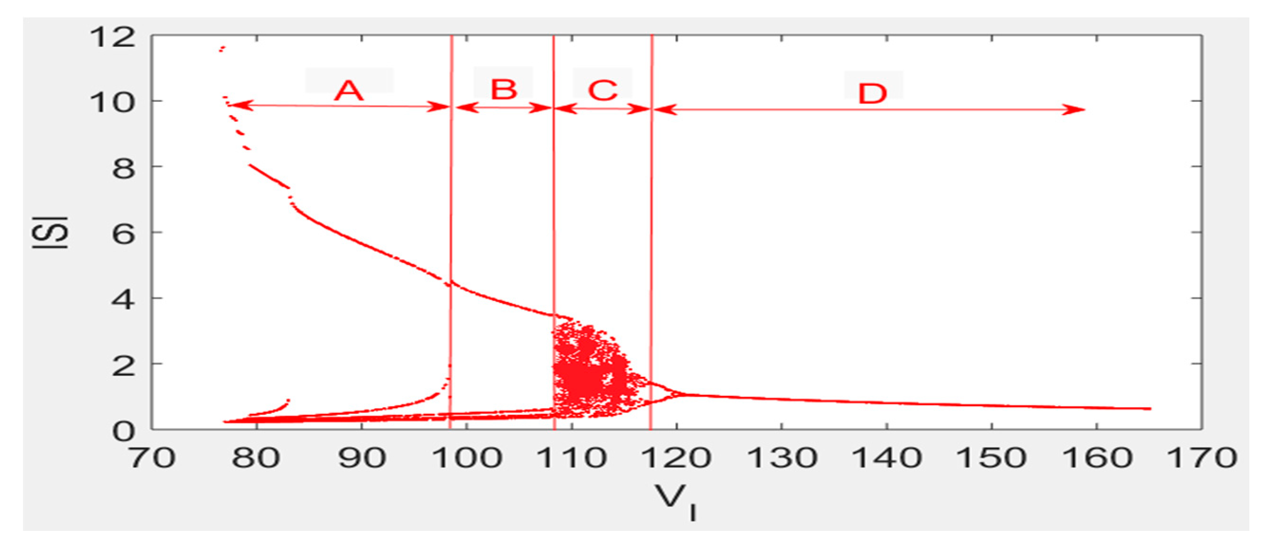
The inter-spike interval bifurcation plot versus the parameter VI in the Chay neuron model is shown in Figure 1. With the change in VI in the range [75, 165], the Chay neuron model reveals rich dynamic characteristics. From Figure 1, we find that the value of VI varies from small to large (marked as region A) and the neuron model enters six cycles and five cycles of periodical discharge patterns. As the VI value continues to increase (region B), when VI = 98.2 mV, the neuron model performs four cycles of cluster discharge activity. As the value of VI increases further, when VI = 107.8 mV, the neuron model enters a chaotic discharge mode, producing the shaded region marked as C in Figure 1. This is the expression in the inter-spike interval bifurcation diagram. As VI increases and the value of VI is greater than 117.6 mV we enter region D. The inter-spike interval sequence is restored to the second-cycle, and the first-cycle discharge mode after an inverse-periodic bifurcation.
3. Synchronization of the Chemical Synaptic-Coupled Chay Neuron System
Synapses have strong adaptability (plasticity) that depend on various external stimuli (such as the action potential of presynaptic neurons). Moreover, chemical synapses can be divided into two types: excitatory and inhibitory [40,41,42,43]. Chemical synapses, which are the most common type of cellular connections in the animal’s nervous system, are highly flexible, making this topic widely studied [44,45,46].
To analyze the synchronous behavior of chemical synaptic-coupled Chay neurons, this paper adopted two chemical synaptic-coupled Chay neuron models as follows:
The following numerical values were adopted: synaptic reversible potential Vsyn = −65, synaptic threshold θ = −45, and ratio constant σ = 10. Equation groups with subscripts 1 and 2 denote sub-systems 1 and 2, respectively. The variable Hsyn represents the coupling strength and Vsyn describes the synapse reversible potential of the neuron, which depends on the presynaptic neuron and the recipient. The parameter θ is the synaptic threshold beyond which its presynaptic neurons begin to act on post-synaptic neurons, and σ denotes the rate constant for the onset of excitation or inhibition. The rest of the variables indicate that the significance and value do not change.
In order to better study the synchronization of coupled neurons, we define the synchronization discrepancy between coupled neurons: e0 = V2 − V1, e1 = n2 − n1, e2 = C2 − C1, and e3 = (|e0| + |e1| + |e2|)/3.
Constructing Lyapunov function as
then the derivative of L is:
The type of substitution (15) can be obtained as follows:
If is established, it needs:
The substitution of e0 = V2 − V1, e1 = n2 − n1 and e2 = C2 − C1 in (17) gives the following:
When Equation (18) is set up, , then we can get the existence and limit of . According to the Lyapunov stability theory, by adjusting the parameters, the , the error state e0, e1, e2 and e3 are asymptotically stable at the origin, namely, , so the system has reached sync.
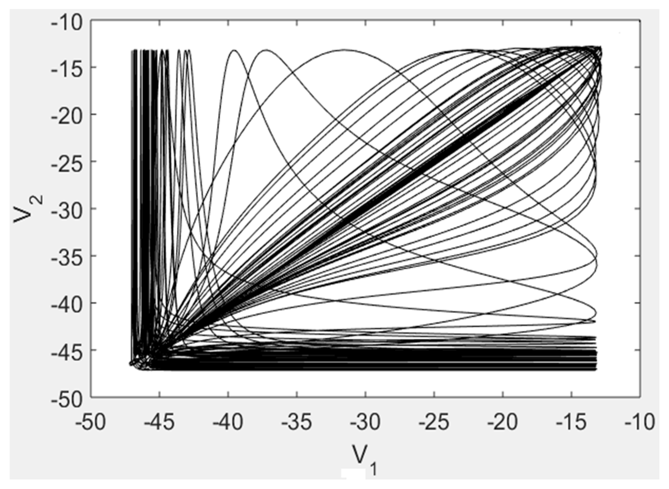
In a first phase, let us consider the discharge activities of two Chay neuron models without the coupling strength. When the coupling strength is Hsyn = 0, solving the two sets of equations leads to the (V1, V2) locus of the two synaptic-coupled Chay neurons shown in Figure 2. The irregular movements indicate that the system is in an asynchronous state. The time history of V1 and V2 are represented in Figure 3. We verify that the values of V1 and V2 are different and that the discharge of the neurons is in a state of chaos; in other words, the system is in a chaotic state. In addition, the synchronization difference map of the coupled neurons is depicted in Figure 3. We observe that the synchronization discrepancy for all time instants indicates that the two neuron system is not in synchronization. In summary, it can be concluded that when Hsyn = 0, the two neuron systems are in a state of chaotic discharge and are in an asynchronous state.
In a second phase, let us consider the coupling strength Hsyn = 0.8 that leads to the (V1, V2) diagram of the chemical synaptic-coupled Chay neuron system shown in Figure 4. The plot is a straight line with a slope of 1, indicating that the system is in a synchronized state. The time evolution of V1 and V2 depicted in Figure 5 shows also that the curves of V1 and V2 coincide. Similarly, it can also be seen from the synchronization discrepancy diagram of Figure 5 that the difference of the synchronization discrepancy with time is always zero, indicating that the coupled neuron system is in a synchronized state. In summary, when the coupling strength is Hsyn = 0.8, the system is in a synchronized state.
It can be concluded after the above analysis that appropriate changes in the coupling strength can induce the synchronization of the chemical synaptic-coupled Chay neuron system.
4. Time-Delay Inhibition of Synchronization of the Chemical Synaptic-Coupled Chay Neuron System
The coupling modes between neurons are divided into two types: electrical and chemical synaptic coupling. The chemical synapses depend on the release of neurotransmitters and are connected by means of dendrites and axons. Furthermore, chemical synapses dominate throughout the neuronal system. Due to the presence of synaptic gaps in the nervous system, there is a significant delay in the transmission of neural signals through the synapse. This effect results in a time delay in the transmission of signals, thereby causing a time lag in the nervous system [47,48,49]. Due to the presence of a time lag, the coupled neurons become an infinite dimensional dynamic system that exhibit a richer nonlinear behavior.
We consider two chemical synaptic-coupled Chay neuron models with time delays as follows:
where t and τ denote time and time lag, respectively. In Equations (19)–(24), the significance and values of other parameters and variables are consistent with Section 2.
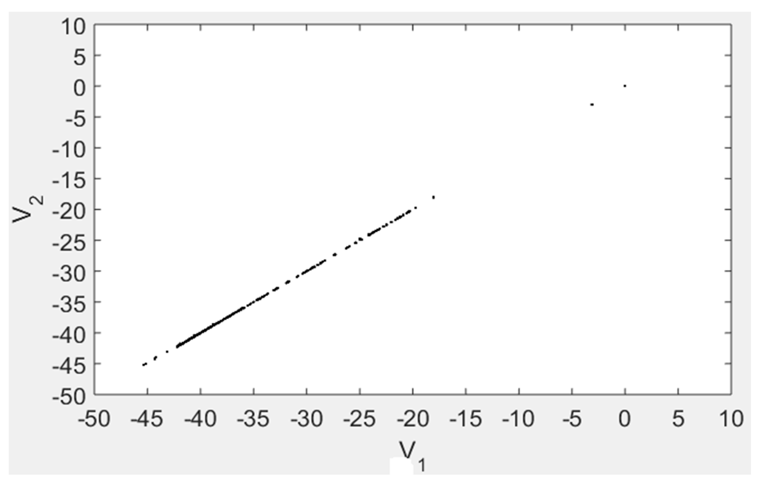
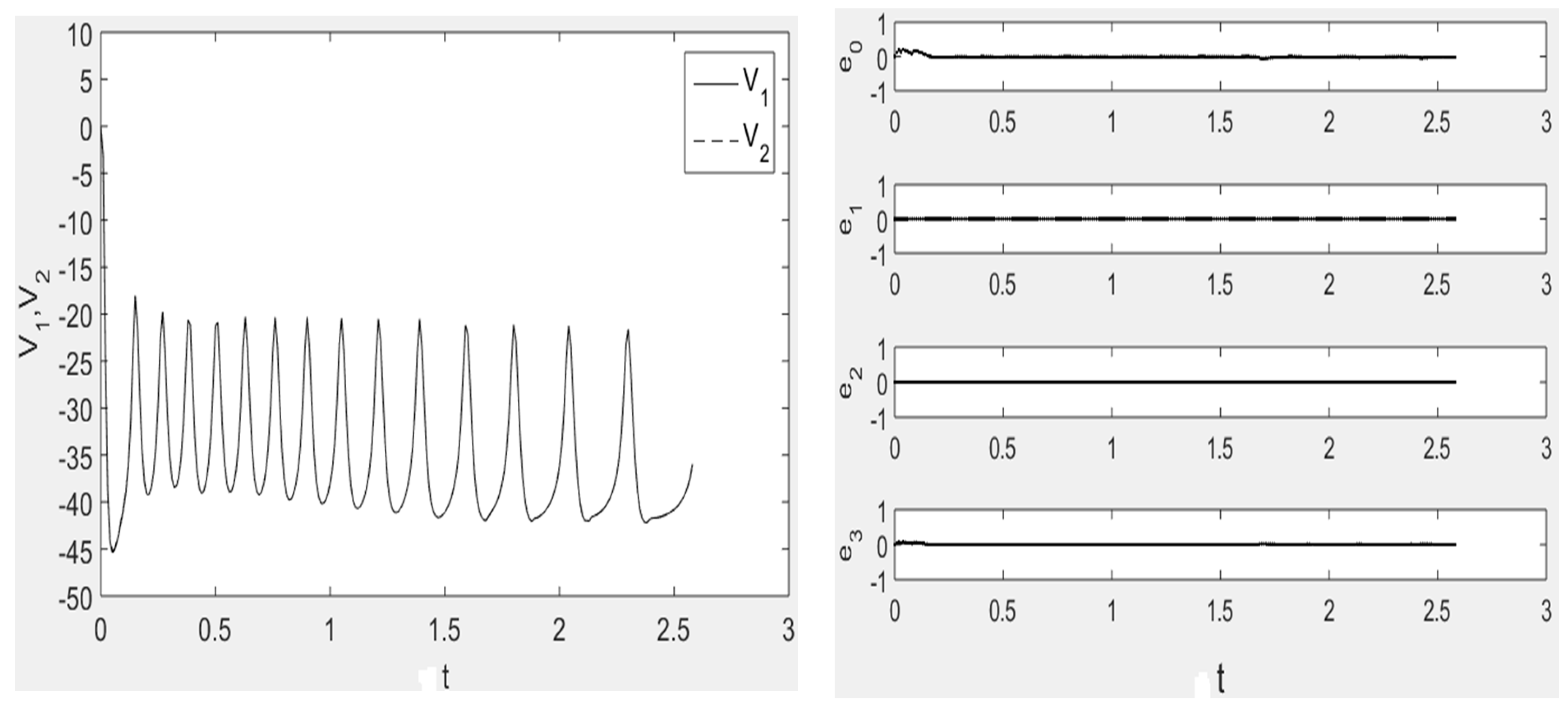
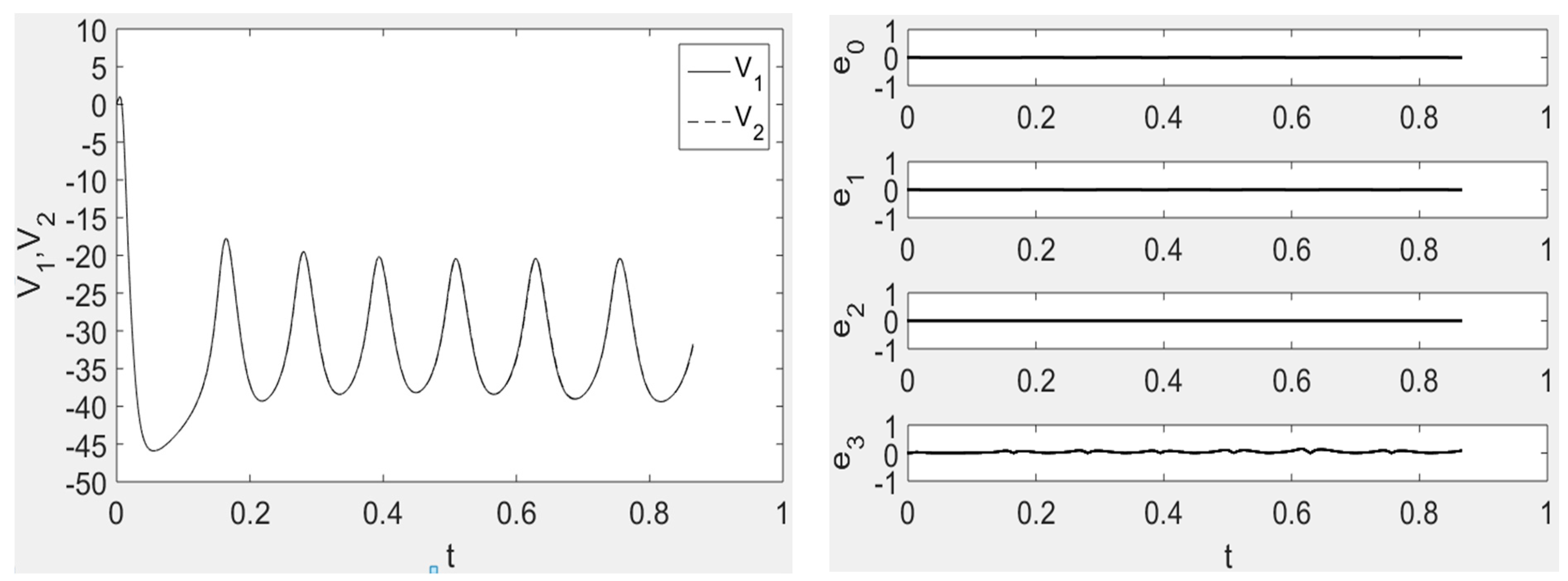
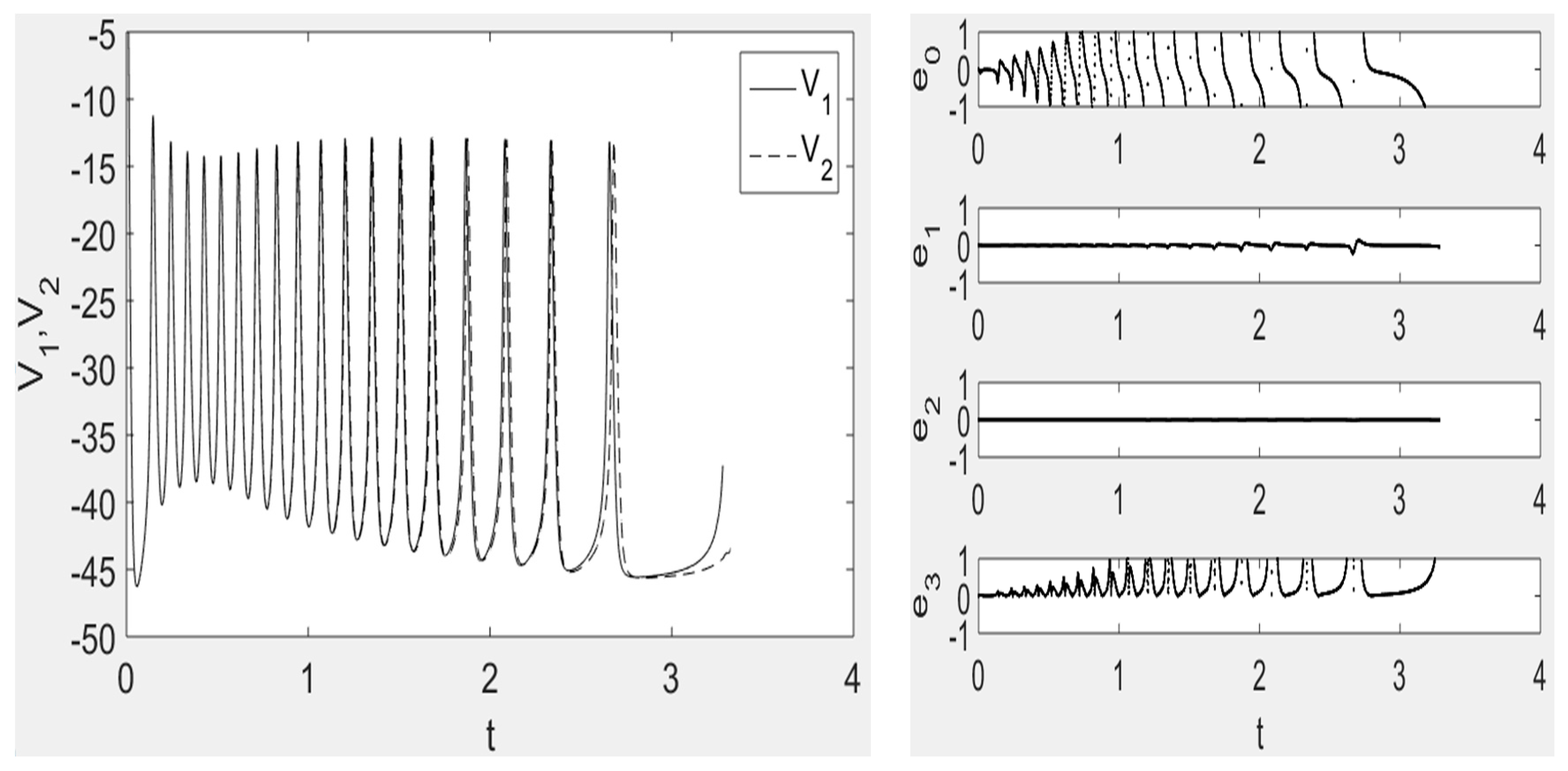
Figure 6 shows the (V1, V2) locus for a coupling strength Hsyn = 1.55 and time lag τ = 0 in the case of the two coupled neuron system (19)–(24). The values of V1 and V2 are identical and the system is in synchronization state. Similarly, the time history diagram of V1 and V2 reveals that the two curves of V1 and V2 overlap. The synchronization difference diagram is also shown in Figure 7, indicating that the two neuron system is in a synchronized state. In summary, when the coupling strength Hsyn = 1.55 and the time lag τ = 0, the two neuron coupling system is in a synchronized state.
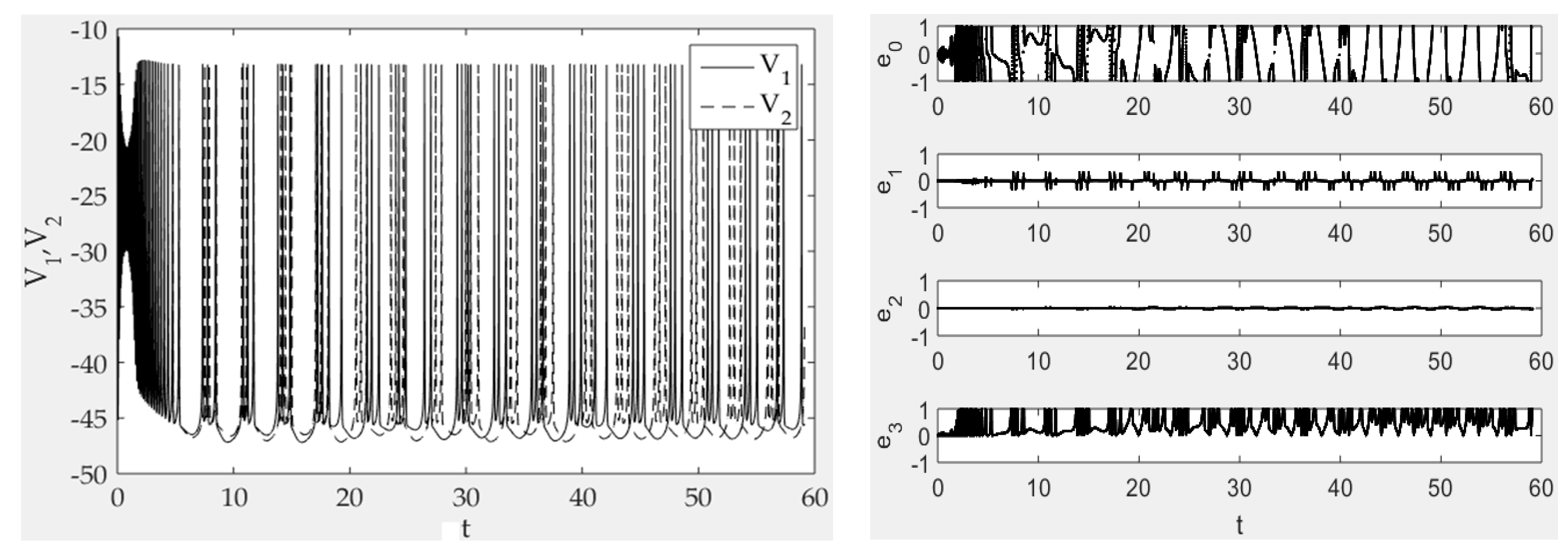
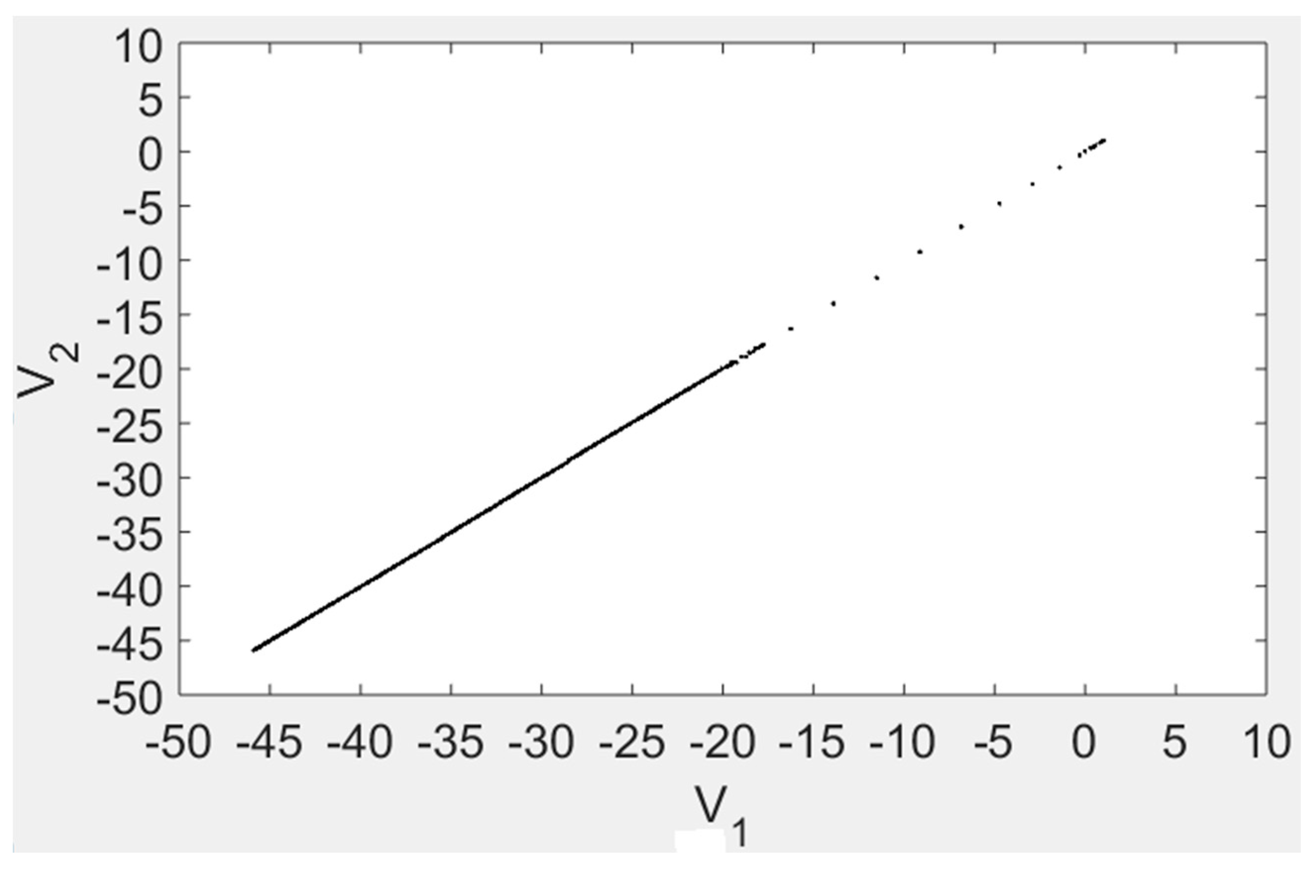
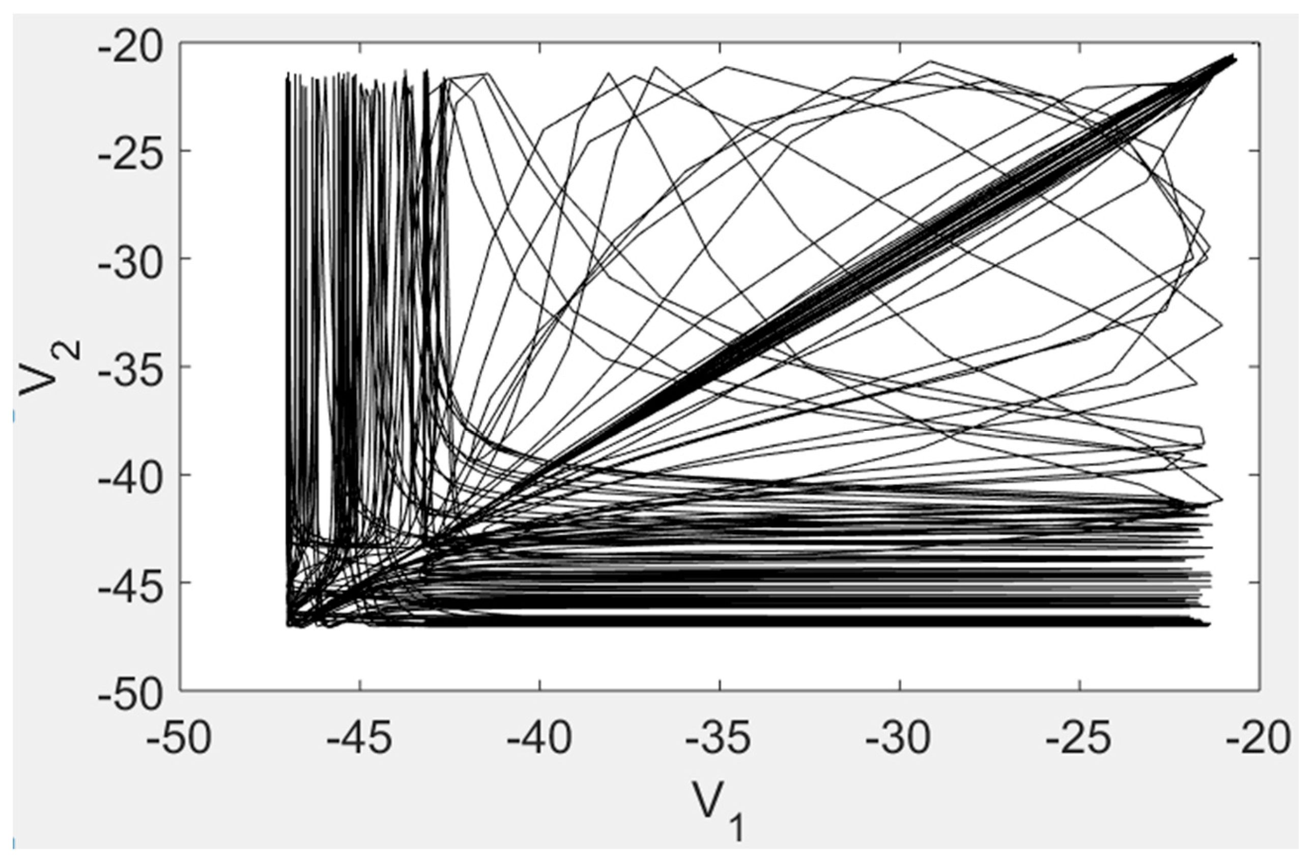
In a third phase, we discuss the synchronization of two chemical synapse-coupled neurons with the coupling strength Hsyn = 1.55 and τ = 3.4. Figure 8 reveals that the locus (V1, V2) has an irregular behavior, indicating that the system is in an asynchronous state. The time history of V1 and V2, illustrated in Figure 9, shows that the two curves do not overlap. Similarly, Figure 9 demonstrates that the synchronization difference between V1 and V2 is always present, revealing that the system does not reach the synchronized state. In summary, the two chemical synaptic coupling Chay neuron system is in an asynchronous state when the coupling strength Hsyn = 1.55 and time lag τ = 3.4.
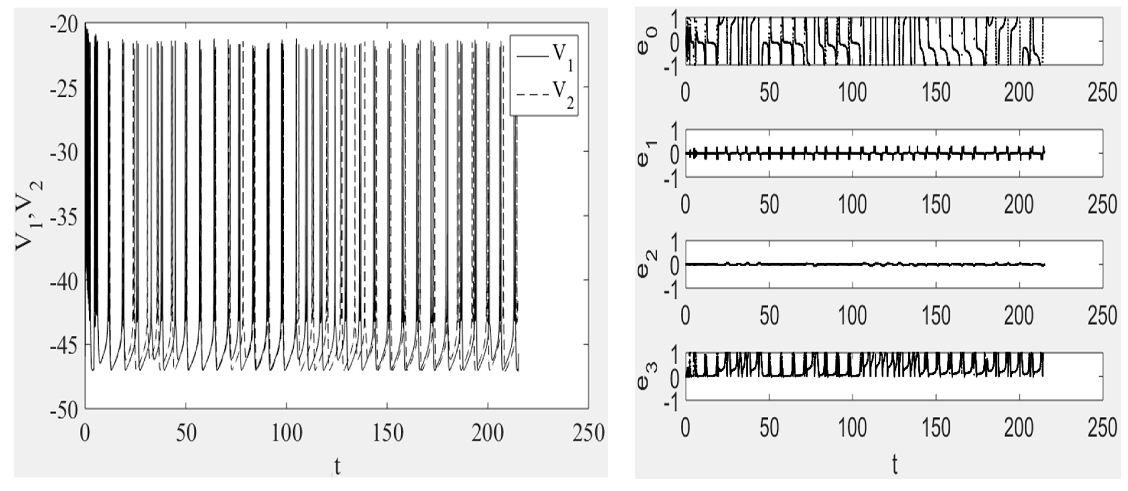
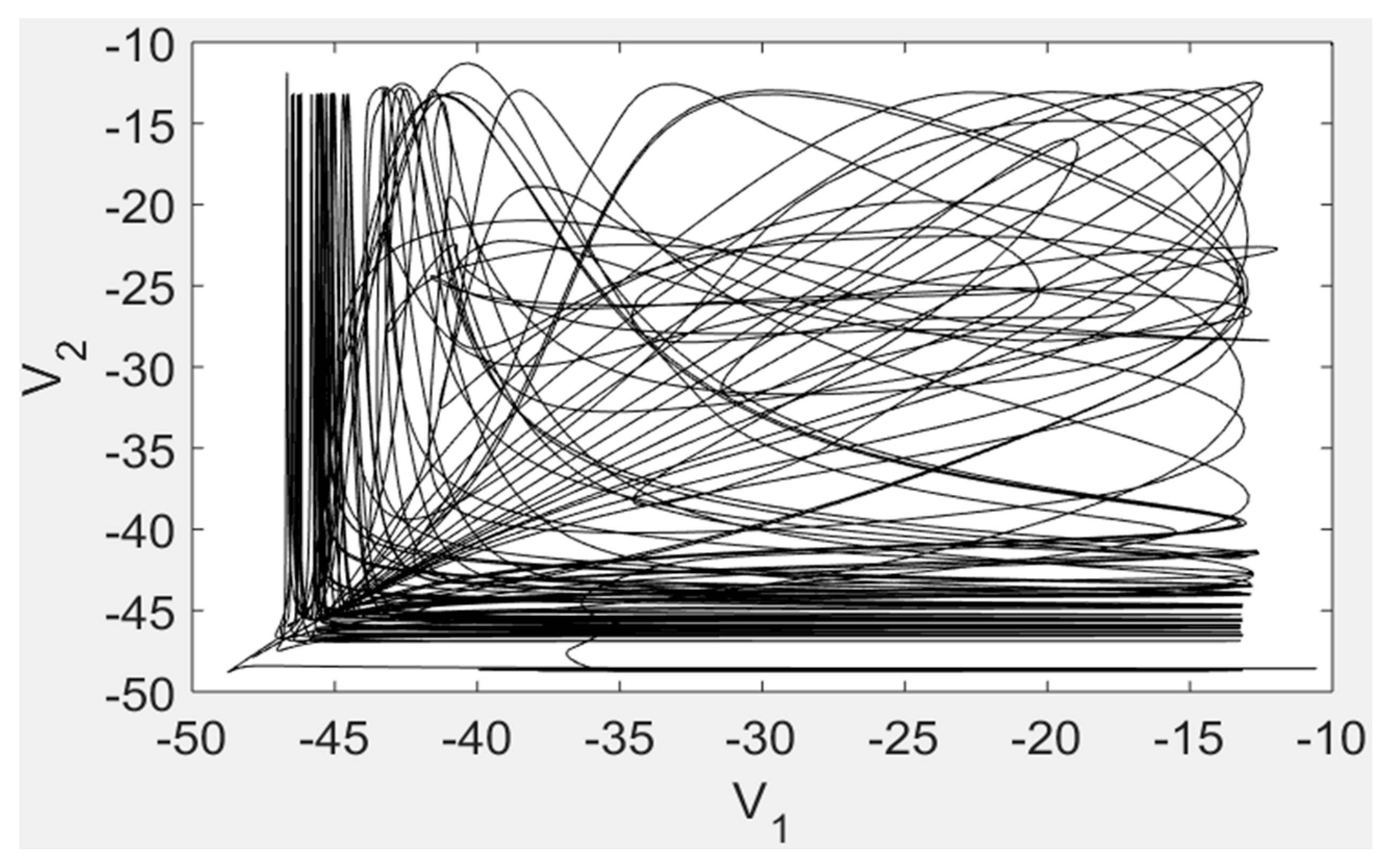
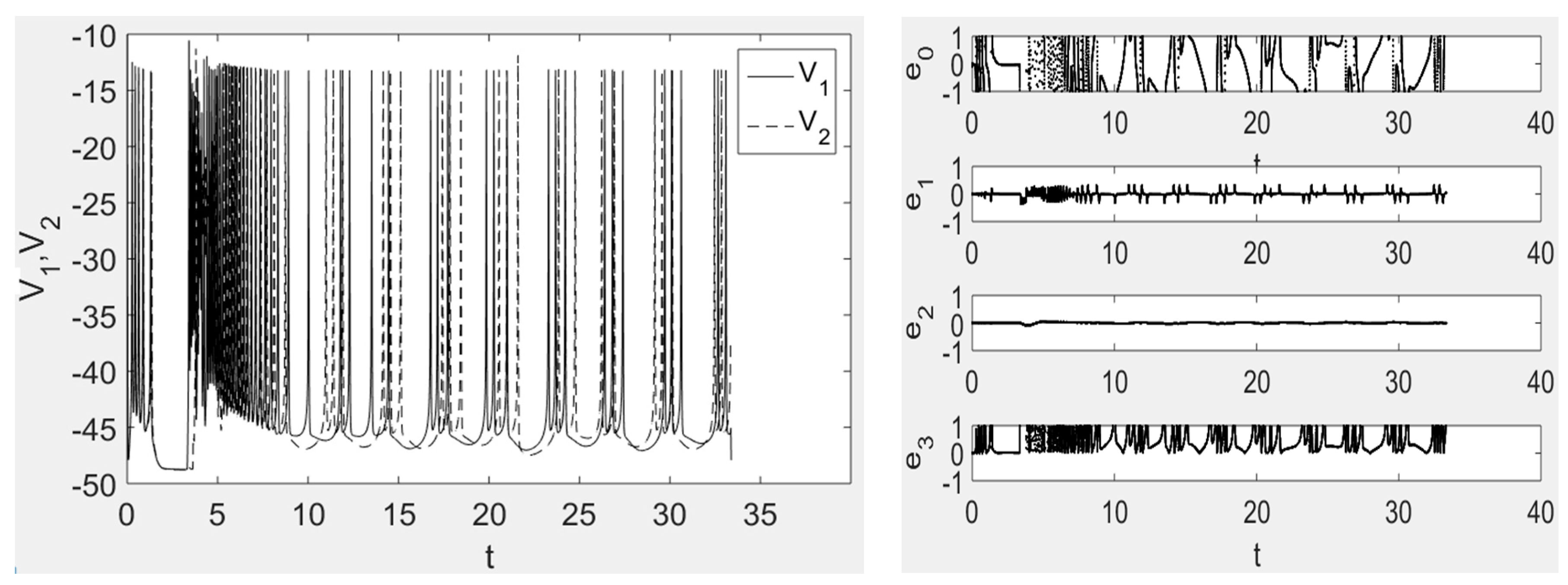
In order to further verify the effect of coupling strength and time delay on the neuron system, this paper fixed the time delay and changed the coupling strength: τ =2.5 and Hsyn = 2.7. By observing Figure 10, the curve of random motion of the system in phase plane shows that the neuron has chaotic discharge activity and the neuron system is in the unsynchronized state. In Figure 11, the time history diagram does not overlap the motion curve of the neurons and the difference of the synchronous difference map is not zero, which indicates that the system is in an asynchronous state.
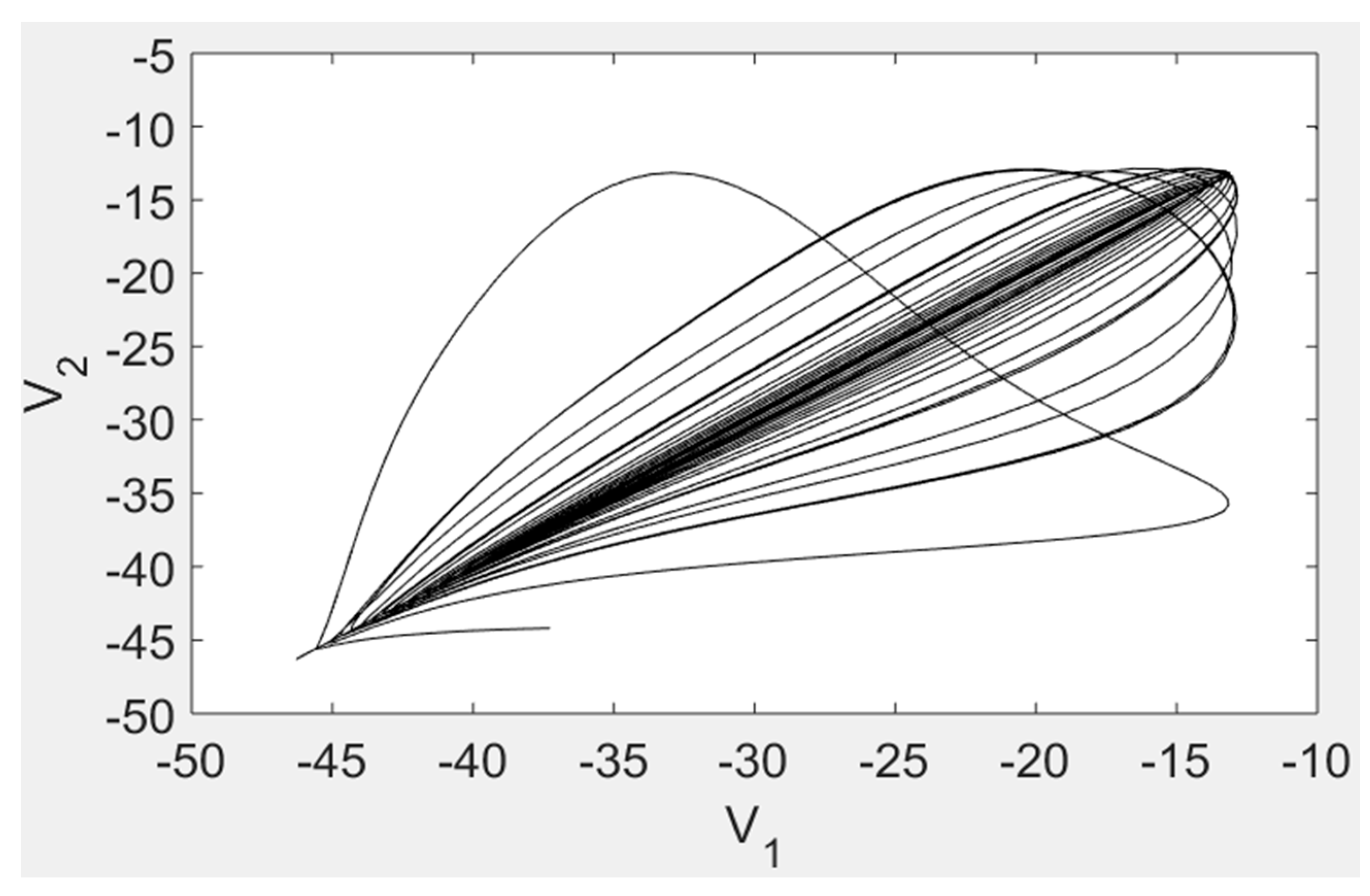
Finally, when the coupling strength increases to Hsyn = 5.3 with τ = 2.5, the phase plane diagram of the coupled neuron system (Figure 12) shows that the trajectory of the system is still an irregular random curve, indicating that the system does not reach the synchronous state. The time history diagram and the synchronous difference diagram in Figure 13 also verify that the system is in an asynchronous state.
From the above discussion, we conclude that the addition of time lags in the two chemical synaptic-coupled Chay neuron system yields a system change from periodic to chaotic discharge activity, leading to the modification from synchronous to non-synchronized state and destroying the original synchronization state.
5. Conclusions
In this paper, the chemical synaptic coupling of a Chay neuron system was studied. The discharge characteristics of the Chay neuron model were analyzed through the state locus, synchronization discrepancy plot, and inter-spike interval bifurcation diagram. The effect of time delay and coupling strength on the coupled Chay neuron system was discussed. The model simulations showed that in a chemical synaptic-coupled Chay neuron system, coupling strength can promote synchronization behavior. Moreover, adding a time delay can inhibit the occurrence of its synchronous behavior, changing from a synchronous to a non-synchronized state. The results have given a deeper insight into the dynamic characteristics of neuron models and provide a basis for further research of neuronal system synchronization.
Author Contributions
Author (1) Kaijun Wu designed the main idea and methods of the paper. Author (2) Dicong Wang implemented the methods of the paper. Author (3) Chao Yu added included extra simulations according to the opinions of the reviewers. Author (4) J. Tenreiro Machado revised the study and perfected the language of the paper.
Acknowledgments
This work was supported by the Natural Science Fund Project of Gansu Province (No. 17JR5RA085) and Foundation of A Hundred Youth Talents Training Problem of Lanzhou Jiaotong University.
Conflicts of Interest
The authors declare no conflict of interest.
References
- Pikovsky, A.; Rosenblum, M.; Kurths, J. Synchronization: A Universal Concept in Nonlinear Sciences Cambridge University Press. Am. J. Phys. 2002, 70, 655. [Google Scholar] [CrossRef]
- Liu, S.; Lu, M.; Liu, G.; Pan, Z. A Novel Distance Matric: Generalized Relative Entropy. Entropy 2017, 19, 269. [Google Scholar] [CrossRef]
- Silva, F.A.D.S.; Lopes, S.R.; Viana, R.L. Synchronization of biological clock cells with a coupling mediated by the local concentration of a diffusing substance. Commun. Nonlinear Sci. Numer. Simul. 2016, 35, 37–52. [Google Scholar] [CrossRef]
- Mahmoud, E.E.; Al-Adwani, M.A. Dynamical behaviors, control and synchronization of a new chaotic model with complex variables and cubic nonlinear terms. Results Phys. 2017, 7, 1346–1356. [Google Scholar] [CrossRef]
- Bader, R. Cochlear spike synchronization and neuron coincidence detection model. Chaos 2018, 28, 023105. [Google Scholar] [CrossRef] [PubMed] [Green Version]
- Liu, S.; Pan, Z.; Fu, W.; Cheng, X. Fractal generation method based on asymptote family of generalized Mandelbrot set and its application. J. Nonlinear Sci. Appl. 2017, 10, 1148–1161. [Google Scholar] [CrossRef] [Green Version]
- Lofredi, R.; Neumann, W.J.; Bock, A.; Horn, A.; Huebl, J.; Siegert, S.; Schneider, G.; Krauss, J.K.; Kühn, A.A. Dopamine-dependent scaling of subthalamic gamma bursts with movement velocity in patients with Parkinson’s disease. eLife 2018, 7, e31895. [Google Scholar] [CrossRef] [PubMed]
- Liu, S.; Pan, Z.; Cheng, X. A Novel Fast Fractal Image Compression Method based on Distance Clustering in High Dimensional Sphere Surface. Fractals 2017, 25, 1740004. [Google Scholar] [CrossRef]
- Ibrahim, S.; Majzoub, S. Adaptive Epileptic Seizure Prediction Based on EEG Synchronization. J. Biomim. Biomater. Biomed. Eng. 2017, 33, 52–58. [Google Scholar] [CrossRef]
- Cornejo-Pérez, O.; Femat, R. Unidirectional synchronization of Hodgkin–Huxley neurons. Chaos 2005, 25, 43–53. [Google Scholar] [CrossRef]
- Jiang, W.; Deng, B.; Tsang, K.M. Chaotic synchronization of neurons coupled with gap junction under external electrical stimulation. Chaos 2004, 22, 469–476. [Google Scholar] [CrossRef]
- Lin, F.F.; Zeng, Z.Z. Synchronization of uncertain fractional-order chaotic systems with time delay based on adaptive neural network control. Acta Phys. Sin. 2017, 66, 40–49. [Google Scholar]
- Deng, B.; Wang, X.J.; Wang, J.; Li, H.Y. Iterative learning control of synchronization of Hodgkin-Huxley neurons. Appl. Res. Comput. 2014, 31, 2656–2660. [Google Scholar]
- Xiu, C.B.; Liu, C.; Guo, F.H.; Cheng, Y.; Luo, J. Control strategy and application of hysteretic chaotic neuron and neural network. Acta Phys. Sin. 2015, 64, 84–91. [Google Scholar]
- Hettiarachchi, I.T.; Lakshmanan, S.; Bhatti, A.; Lim, C.P.; Prakash, M.; Balasubramaniam, P.; Nahavandi, S. Chaotic synchronization of time-delay coupled Hindmarsh–Rose neurons via nonlinear control. Nonlinear Dyn. 2016, 86, 1249–1262. [Google Scholar] [CrossRef]
- Pinto, R.D.; Varona, P.; Volkovskii, A.R.; Szücs, A.; Abarbanel, H.D.; Rabinovich, M.I. Synchronous behavior of two coupled electronic neurons. Phys. Rev. E Stat. Phys. Plasmas Fluids Relat. Interdiscip. Top. 2000, 62, 2644–2656. [Google Scholar] [CrossRef] [Green Version]
- Subramanian, K.; Muthukumar, P.; Lakshmanan, S. State feedback synchronization control of impulsive neural networks with mixed delays and linear fractional uncertainties. Appl. Math. Comput. 2018, 321, 267–281. [Google Scholar] [CrossRef]
- Lu, M.Y.; Liu, S.; Kumarsangaiah, A.; Zhou, Y.P.; Pan, Z.; Zuo, Y.C. Nucleosome Positioning with Fractal Entropy Increment of Diversity in Telemedicine. IEEE Access 2018. [Google Scholar] [CrossRef]
- Far, S. Hybrid Synchronization of Uncertain Generalized Lorenz System by Adaptive Control. J. Control Sci. Eng. 2018, 2018, 1–5. [Google Scholar] [Green Version]
- Liu, S.; Pan, Z.; Song, H. Digital image watermarking method based on DCT and fractal encoding. IET Image Process. 2017, 11, 815–821. [Google Scholar] [CrossRef]
- Mobayen, S.; Tchier, F. Composite nonlinear feedback control technique for master/slave synchronization of nonlinear systems. Nonlinear Dyn. 2017, 87, 1731–1747. [Google Scholar] [CrossRef]
- Sipahi, R.; Niculescu, S.I.; Abdallah, C.T.; Michiels, W. Stability and Stabilization of Systems with Time Delay. Control Syst. IEEE 2011, 31, 38–65. [Google Scholar] [CrossRef]
- Delice, I.I.; Sipahi, R. Delay-Independent Stability Test for Systems with Multiple Time-Delays. IEEE Trans. Autom. Control 2012, 57, 963–972. [Google Scholar] [CrossRef]
- Min, H.K.; Sipahi, R. Effects of Edge Elimination on the Delay Margin of a Class of LTI Consensus Dynamics. IEEE Trans. Autom. Control 2018, 1, 99. [Google Scholar]
- Gao, Q.; Olgac, N. Stability analysis for LTI systems with multiple time delays using the bounds of its imaginary spectra. Syst. Control Lett. 2017, 102, 112–118. [Google Scholar] [CrossRef]
- Cepeda-Gomez, R.; Olgac, N. Stability of formation control using a consensus protocol under directed communications with two time delays and delay scheduling. Int. J. Syst. Sci. 2016, 47, 433–449. [Google Scholar] [CrossRef]
- Turkoglu, K.; Olgac, N. Robust Control for Multiple Time Delay MIMO Systems with Delay—Decouplability Concept. In Topics in Time Delay Systems; Springer: Berlin/Heidelberg, Germany, 2009; pp. 37–47. [Google Scholar]
- Sun, F.; Turkoglu, K. Nonlinear Consensus Strategies for Multi-Agent Networks in Presence of Communication Delays and Switching Topologies: Real-Time Receding Horizon Approach; Elsevier; San José State University: San José, CA, USA, 2016. [Google Scholar]
- Hongming, L.I.; Zhang, S. The Hopf Bifurcation Analysis of the Neuronal Chay Model under Constant Current Stimulation. J. Taiyuan Univ. Technol. 2013, 44, 123–126. [Google Scholar]
- Chintala, V.; Subramanian, K.A. A numerical investigation of the dynamics of a system of two time-delay coupled relaxation oscillators. Commun. Pure Appl. Anal. 2017, 2, 567–577. [Google Scholar]
- Zheng, Y.; Lu, Q. Synchronization in ring coupled chaotic neurons with time delay. J. Dyn. Control 2008, 3, 208–212. [Google Scholar]
- Kumar, R.; Srivastava, S.; Gupta, J.R.P.; Mohindru, A. Diagonal recurrent neural network based identification of nonlinear dynamical systems with Lyapunov stability based adaptive learning rates. Neurocomputing 2018, 287, 102–117. [Google Scholar] [CrossRef]
- Cao, Y.; Wen, S.; Chen, M.Z.Q.; Huang, T.; Zeng, Z. New results on anti-synchronization of switched neural networks with time-varying delays and lag signals. Neural Netw. 2016, 81, 52–58. [Google Scholar] [CrossRef] [PubMed]
- Rekabdar, B.; Nicolescu, M.; Kelley, R. An Unsupervised Approach to Learning and Early Detection of Spatio-Temporal Patterns Using Spiking Neural Networks. J. Intell. Robot. Syst. 2015, 80, 83–97. [Google Scholar] [CrossRef]
- Rekabdar, B.; Nicolescu, M.; Saffar, M.T.; Kelley, R. A Scale and Translation Invariant Approach for Early Classification of Spatio-Temporal Patterns Using Spiking Neural Networks. Neural Process. Lett. 2016, 43, 327–343. [Google Scholar] [CrossRef]
- Xiao, S.P.; Lian, H.H.; Zeng, H.B.; Chen, G.; Zheng, W.H. Analysis on robust passivity of uncertain neural networks with time-varying delays via free-matrix-based integral inequality. Int. J. Control Autom. Syst. 2017, 15, 1–10. [Google Scholar] [CrossRef]
- Chay, T.R. Eyring rate theory in excitable membranes: Application to neuronal oscillations. J. Phys. Chem. 1983, 87, 2935–2940. [Google Scholar] [CrossRef]
- Chay, T.R. Chaos in a three-variable model of an excitable cell. Physica D 1985, 16, 233–242. [Google Scholar] [CrossRef]
- Chay, T.R.; Fan, Y.S.; Lee, Y.S. Bursting, Spiking, Chaos, Fractals, And Universality In Biological Rhythms. Int. J. Bifurc. Chaos 1995, 5, 595–635. [Google Scholar] [CrossRef]
- Han, F.; Wang, Z.; Du, Y.; Sun, X.; Zhang, B. Robust synchronization of bursting Hodgkin–Huxley neuronal systems coupled by delayed chemical synapses. Int. J. Non Linear Mech. 2014, 70, 105–111. [Google Scholar] [CrossRef]
- Batista, C.A.S.; Viana, R.L.; Lopes, S.R.; Batista, A.M. Dynamic range in small-world networks of Hodgkin–Huxley neurons with chemical synapses. Physica A 2014, 410, 628–640. [Google Scholar] [CrossRef]
- Hu, D.; Cao, H. Stability and synchronization of coupled Rulkov map-based neurons with chemical synapses. Commun. Nonlinear Sci. Numer. Simul. 2016, 35, 105–122. [Google Scholar] [CrossRef]
- Dieterich, D.C.; Kreutz, M.R. Proteomics of the Synapse—A Quantitative Approach to Neuronal Plasticity. Mol. Cell. Proteom. 2016, 15, 368–381. [Google Scholar] [CrossRef] [PubMed]
- Liu, P.; Chen, B.; Mailler, R.; Wang, Z.W. Antidromic-rectifying gap junctions amplify chemical transmission at functionally mixed electrical-chemical synapses. Nat. Commun. 2017, 8, 14818. [Google Scholar] [CrossRef] [PubMed] [Green Version]
- Wu, K.J.; Wang, C.L.; Shan, Y.Z.; Du, S.S.; Lu, H.W. Chemical synapse coupling synchronization of Hindmarsh-Rose neurons under Gauss white noise. Jilin Daxue Xuebao 2017, 47, 1554–1560. [Google Scholar]
- Kuo, S.P.; Schwartz, G.W.; Rieke, F. Nonlinear Spatiotemporal Integration by Electrical and Chemical Synapses in the Retina. Neuron 2016, 90, 320–332. [Google Scholar] [CrossRef] [PubMed]
- Minneci, F.; Kanichay, R.T.; Silver, R.A. Estimation of the time course of neurotransmitter release at central synapses from the first latency of postsynaptic currents. J. Neurosci. Methods 2012, 205, 49–64. [Google Scholar] [CrossRef] [PubMed]
- Sakaguchi, H.; Tobiishi, S. Synchronization and Spindle Oscillation in Noisy Integrate-and-Fire-or-Burst Neurons with Inhibitory Coupling. Prog. Theor. Phys. 2012, 114, 539–554. [Google Scholar] [CrossRef]
- Wu, K.J.; Shan, Y.Z.; Wang, C.L.; Lu, H.W. Study on Synchronization of Chemical Synapse Coupled Hindmarsh-Rose Neurons under Time Delay. Chin. Q. Mech. 2017, 1, 123–134. [Google Scholar]
Figure 1.
Inter-spike interval bifurcation diagram versus the parameter VI.

Figure 2.
Locus (V1, V2) when Hsyn = 0.

Figure 3.
Time history diagram and synchronization discrepancy graph when Hsyn = 0.

Figure 4.
Locus (V1, V2) when Hsyn = 0.8.

Figure 5.
Time history diagram and synchronization discrepancy diagram when Hsyn = 0.8.

Figure 6.
Locus (V1, V2) when Hsyn = 1.55 and τ = 0.

Figure 7.
Time histogram and synchronization discrepancy graph when Hsyn = 1.55 and τ = 0.

Figure 8.
Locus (V1, V2) when Hsyn = 1.55 and τ = 3.4.

Figure 9.
Time histogram and synchronization discrepancy graph when Hsyn = 1.55 and τ = 3.4.

Figure 10.
Locus (V1, V2) when τ = 2.5 and Hsyn = 2.7.

Figure 11.
Time histogram and synchronization discrepancy graph when τ = 2.5 and Hsyn = 2.7.

Figure 12.
Locus (V1, V2) when τ = 2.5 and Hsyn = 5.3.

Figure 13.
Time histogram and synchronization discrepancy graph when τ = 2.5 and Hsyn = 5.3.


Table 1.
Values of Chay neuron model parameters.
| gI = 1800 s−1 | gK,V = 1700 s−1 | gL = 12 s−1 | gK,C = 17 s−1 |
| VK = −68 mV | VL = −40 mV | VC = 200 mV | KC = 3.3/18 |
| λn = 223.8 | = 0.27 mV−1s−1 |
© 2018 by the authors. Licensee MDPI, Basel, Switzerland. This article is an open access article distributed under the terms and conditions of the Creative Commons Attribution (CC BY) license (http://creativecommons.org/licenses/by/4.0/).
Share and Cite
MDPI and ACS Style
Wu, K.; Wang, D.; Yu, C.; Machado, J.T. Synchronization of Chemical Synaptic Coupling of the Chay Neuron System under Time Delay. Appl. Sci. 2018, 8, 927. https://0-doi-org.brum.beds.ac.uk/10.3390/app8060927
AMA Style
Wu K, Wang D, Yu C, Machado JT. Synchronization of Chemical Synaptic Coupling of the Chay Neuron System under Time Delay. Applied Sciences. 2018; 8(6):927. https://0-doi-org.brum.beds.ac.uk/10.3390/app8060927
Chicago/Turabian StyleWu, Kaijun, Dicong Wang, Chao Yu, and Jose Tenreiro Machado. 2018. "Synchronization of Chemical Synaptic Coupling of the Chay Neuron System under Time Delay" Applied Sciences 8, no. 6: 927. https://0-doi-org.brum.beds.ac.uk/10.3390/app8060927
Note that from the first issue of 2016, this journal uses article numbers instead of page numbers. See further details here.