1. Introduction
During the recent rapid advances in science and technology, bearing technology has been extensively used in mechanical structures. However, as a hydrodynamic bearing–rotor system rotates at a critical frequency [
1,
2], the interactions of the surrounding fluid in the bearing–rotor system will produce subsynchronous self–excited vibrations of large amplitude that track running speed and make the system be unstable. The fluid–induced instability behaviors are oil whirl and oil whip. These interactions will make the rotor impact the wall of the journal bearing, and cause dry friction that damages the mechanical components. In view of this, how to cope with fluid–induced instability for the hydrodynamic bearing–rotor system has attracted much attention in the recent years.
In the past, there have been many solutions proposed to eliminate the instabilities of a fluid bearing. Some articles have discussed how to enhance the dynamic bearing performance using a groove design. Naimi et al. [
3] discussed the influence of a circumferential groove for a hydrodynamic short bearing. Brito et al. [
4] showed the performance of a journal bearing with a single and twin axial groove configuration. Bently and his research team [
5,
6,
7,
8] showed that dynamic stiffness and viscosity are unstable factors in a rotor system which will affect the rotating of the whirl and whip, and they also showed that the oil whirl phenomenon will occur at about 0.47 times the frequency of the rotation speed, indicating the effect of bearing rigidity and pressure. Furthermore, some researchers have used an extra actuator to change the stiffness of the rotor–bearing system. Fan et al. [
9,
10,
11] used electromagnetic exciters to increase the stiffness of the rotor–bearing system to raise its threshold to a higher stability and eliminate the whip instability.
Ferrofluids are colloidal liquids made of nanoscale ferromagnetic, or ferrimagnetic, particles suspended in a carrier fluid. The properties of ferrofluid are similar in nature to the carrier liquid in the absence of an external magnetic field. When an external magnetic field acts, the ferrofluid exhibits the characteristics of a magnetic material and has controllability and rheology. Ferrofluids exhibit many special effects, and have high academic value and application prospects [
12,
13]. In recent years, with the development of nanotechnology, many applications have been proposed, and they have mainly been used in three major areas: space technology, damping mechanisms, and in shaft sealing technology and hydrodynamic bearings. A dynamic equation has been proposed for a hydrodynamic bearing–rotor system lubricated by ferrofluid, which has shown that ferrofluid applied on the oil–film bearing can improve the viscosity and the load–carrying capacity in a magnetic field [
14,
15,
16,
17,
18,
19,
20,
21,
22].
Several researchers [
23,
24,
25] have discussed the change of the bearing capacity of a sliding bearing under the influence of an external magnetic field. Uhlmann et al. [
26,
27] have studied the influence of external magnetic field on the friction performance of journal bearings. The experimental results show that the addition of magnetic fluid can effectively reduce the wear.
This study builds a single–oil wedge hydrodynamic bearing–rotor system as the test platform, and uses ferrofluid as the lubrication oil which can be controlled by the magnetic field to improve the performance of the hydrodynamic bearing. Experimental results showed that the bearing stability threshold conditions will be increased by the external magnetic fields and the stiffness of the magnetic fluid is also increased.
2. Model of a Single–Oil Wedge Hydrodynamic Bearing–Rotor System
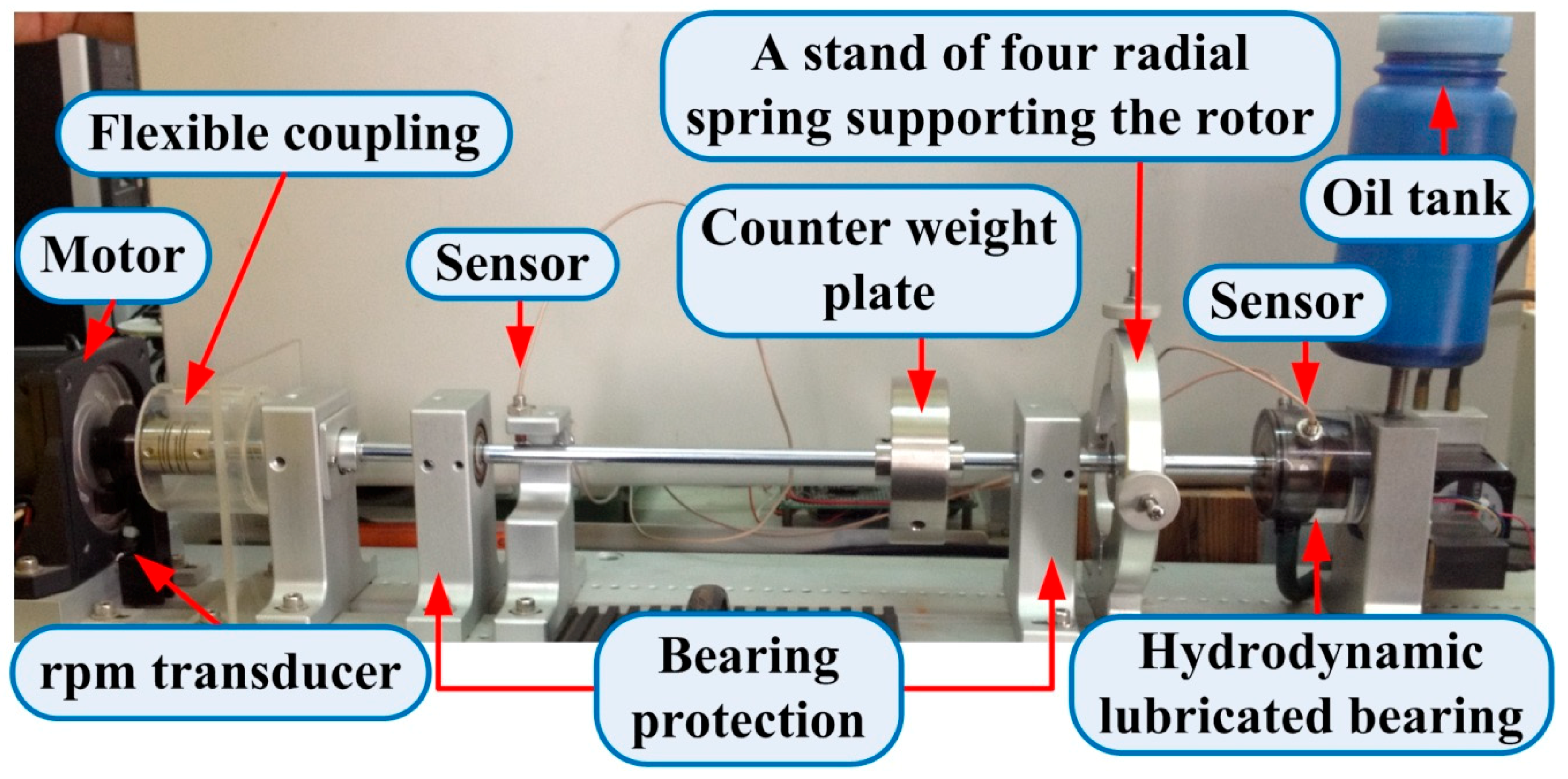
The photograph of the test platform for this study is shown in
Figure 1. A stainless shaft with a 9.52 mm diameter and 490 mm length was supported by a relatively rigid Oilite bronze bushing and a cylindrical, fluid–lubricated bearing. The horizontal shaft was driven by a 90 watt AC induction motor with a variable speed controller. An rpm transducer at the left end was combined with a rotating disk, which has a square slit and mounted on the shaft, and a photo interrupter is used to detect the speed as the motor rotates. A flexible coupling connects the motor shaft and the stainless shaft. A single–oil wedge hydrodynamic bearing was set at the right end. The type of the hydrodynamic bearing was a circle wedge. Two eddy current sensors set on the outside case of the bearing and the other two eddy current sensors installed next to bearing protection are used to measure the displacements of the journal and shaft. An oil tank installed above journal bearing to store ferrofluid. A stand of four radial spring supporting the rotor was used to position the initial position of the rotor journal to the center of the fluid–film bearing during the experiment. In the midspan, one 0.78 kg counterweight plate was attached to the shaft. Two seals made of bronze as bearing protections were located at both sides of the mass disc to protect the rotor system.
A centerline adjuster was used to position the rotor journal to the center of the fluid–film bearing during the experiment. Vibration data were obtained from two pairs of XY eddy current transducers located in the fluid–lubricated bearing shell and located near the seal, respectively, and an rpm transducer was installed next to the flexible coupling in order to obtain rpm signals.
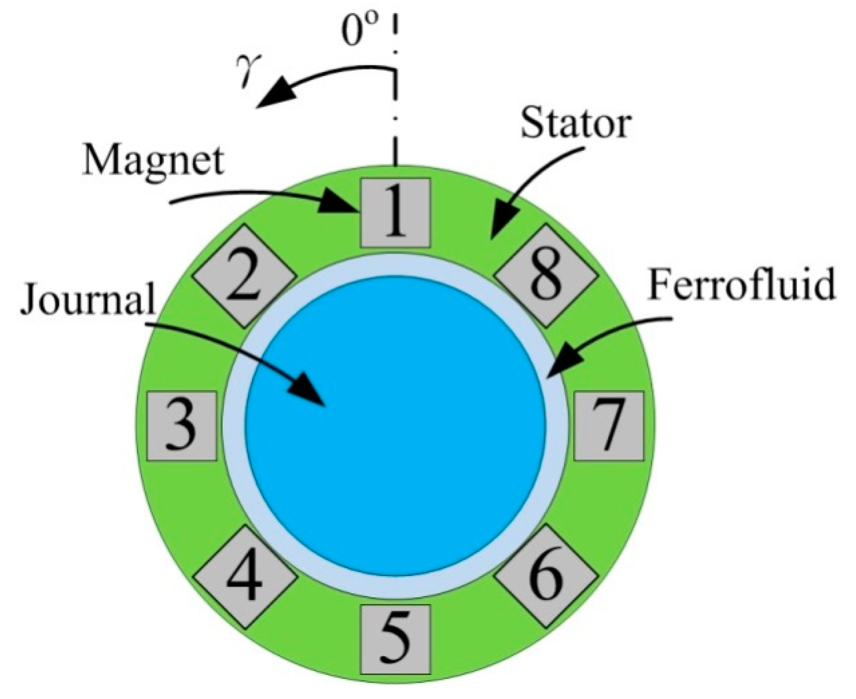
There were two eddy current sensors set on the outside case of the bearing to measure the displacements of the journal. Also, there were eight slots in the outside case which were used to install the permanent magnets. The permanent magnets are cylindrical magnets with a diameter of 10 mm and a height of 20 mm, and the material is NdFeB N35. The serial numbers of the magnets are shown in
Figure 2. In this study, 3 to 8 magnets were inserted into the eight slots around the bearing to form four different types of magnetic fields.
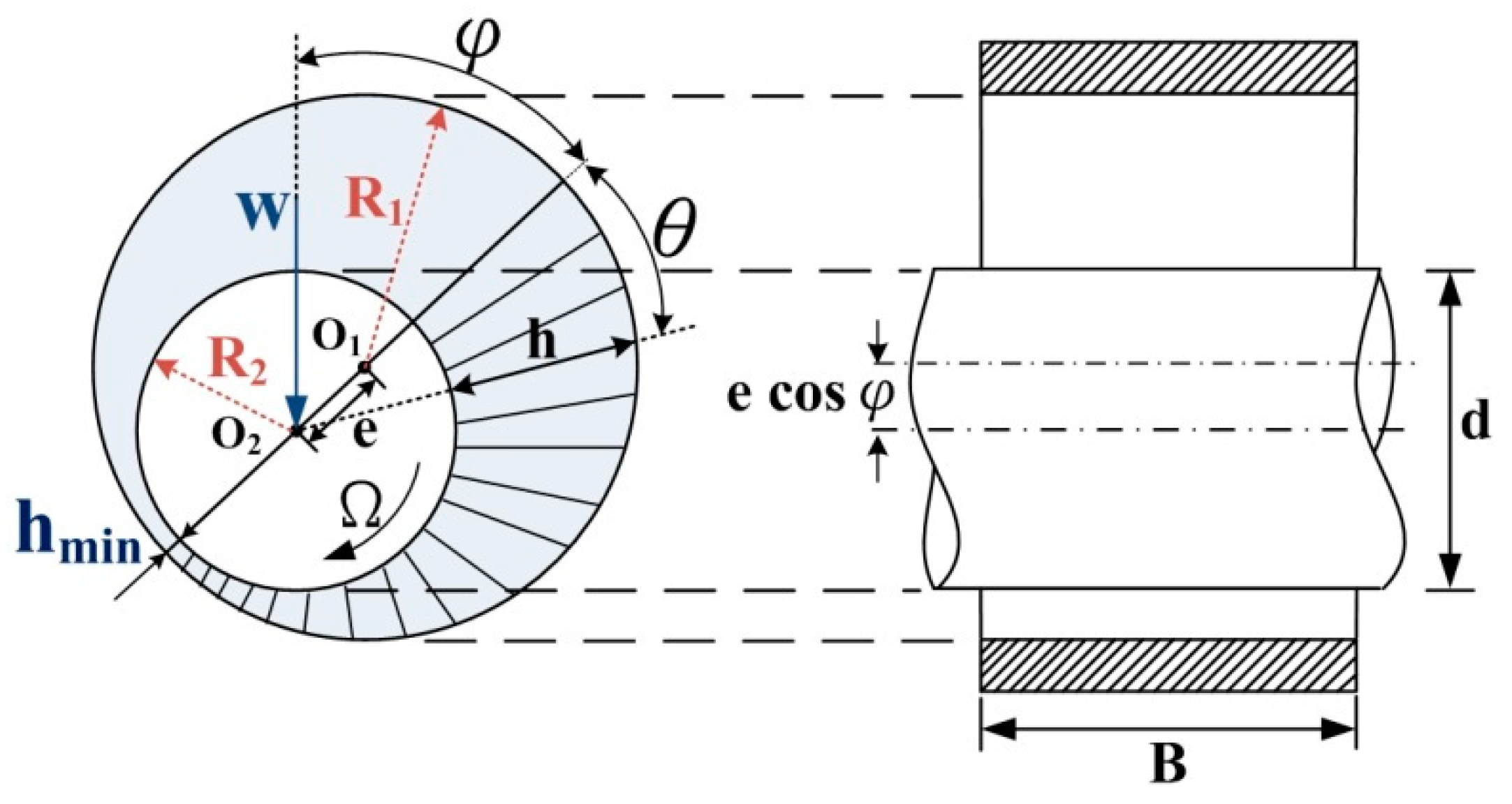
Assuming that the fluid is stable and flows as a laminar flow, the pressure distribution of the hydrodynamic bearing can be shown as in
Figure 3. In the figure,
O1 is the geometric center of the fluid bearing and
R1 is the bearing radius,
O2 is the center of the journal under a load
W applied at the journal, the acute angle
φ of line
O1O2 and the load line is called the attitude angle,
Ω is the rotating speed,
d is the journal diameter, and
R2 is the journal radius,
c is the gap of the journal and bearing, eccentricity
e is the distance of
O1 and O
2,
h is the oil film thickness, and
hmin is the minimum oil film thickness and equal to
c minus
e.
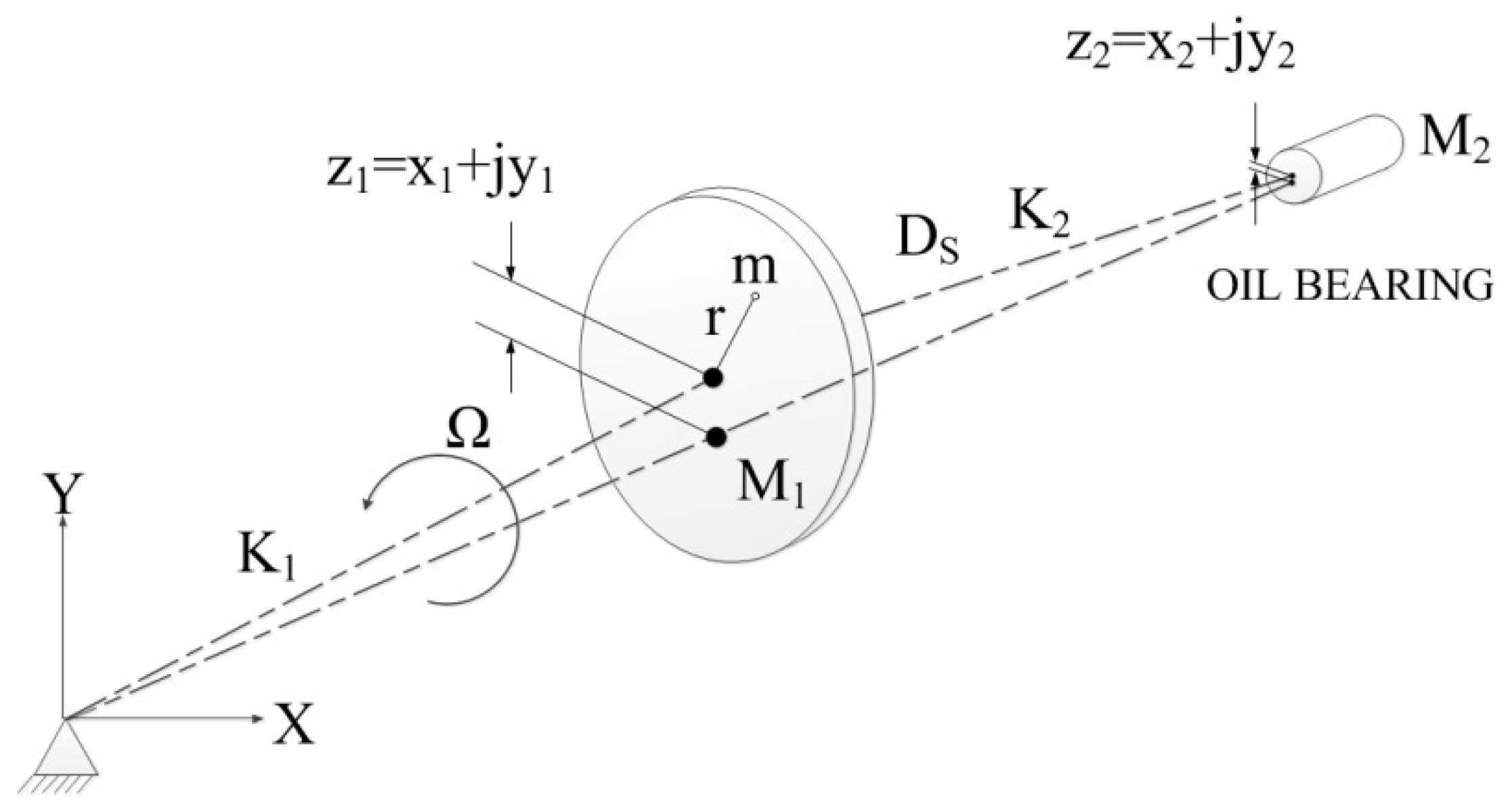
Figure 4 displays the model of a symmetric rigid rotor system. According the research of Muszynska [
28], the mathematical model which represents the balance of forces in the symmetric rotor can be expressed as
where
z1 (
t) and
z2 (
t) are the displacements of the right and left node points,
M1 and
M2 are the masses of the mass disk and the rotor disk of bearing,
DS is the generalized external damping coefficient,
K0 is the radial rigidity of the oil film,
K1 and
K2 are the rigidity coefficients of the shaft,
K3 is the radial rigidity provided by the spring outside the journal which balances the gravity of the journal,
φ is the nonlinear radial rigidity of the fluid,
Ω is the rotation speed, and
λ is the average speed ratio in the fluid, and
m and
r are mass and radius of modal unbalance, respectively.
D and
Mf are damping and inertia coefficients respectively.
and
are nonlinear functions of the radial displacement, respectively.
Equation (1) can be linearized, and the eigenvalue is taken to deduce the following instability threshold speed
Expand the value in the root number, the equation can be rewritten as
K1 is the rigidity coefficient of the flexible coupling to the mass disc. Since one end is fixed by the flexible coupling, the rigidity coefficient
K1 is large.
K2 is the rigidity coefficient of the mass disc to the fluid bearing, far from the fixed end, and the coefficient
K2 is less than
K1. K0 is the radial stiffness of the oil film, the rigidity coefficient provided by the liquid is also smaller than the rigidity coefficient provided by the flexible coupling.
K3 is the radial stiffness provided by the spring outside the journal. The characteristics of the spring itself provide a small coefficient of rigidity. Thus,
K2,
K0 + K3 are smaller than
K1, and the value in the root number can approximate to
where
Ωth is distinguished as the instability threshold speed.
The above equation can be reduced to , i.e., the instability threshold speed of the rotor can be increased by reducing λ, increasing K1, or reducing M1. However, M1 is rarely changed as the rotor system has been set up. Only λ and K1 can be handled to change the instability threshold speed. In terms of oil bearing, the viscosity of the lubricating fluid is one of the conditions that can be used to change the value of K1, and the higher the lubricating fluid viscosity, the greater the K1, and the less likely the system will cause fluid instability.
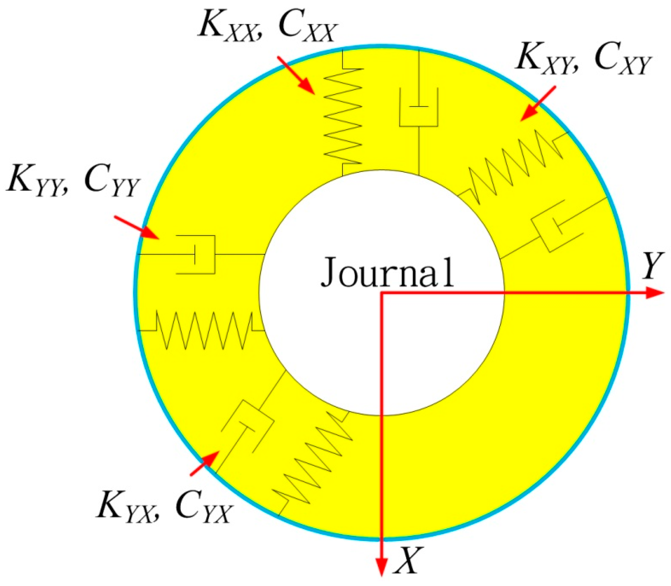
3. Dynamic Force Coefficients of a Single–Oil Wedge Hydrodynamic Bearing
According to the study of Childs [
29], the coefficients of stiffness and damping of a hydrodynamic bearing can be expressed as
The first subscript represents the direction of the corresponding stiffness, and the second subscript represents the direction of displacement. The stiffness coefficients (
KXX,
KYY) and (
KXY,
KYX) are called the direct stiffness term and coupled stiffness term.
Figure 5 shows the directions of the different stiffness and damping terms.
The inertia or additional mass coefficient {
Mij}
ij = X,
Y can be defined as
. The term
is the acceleration of the journal center. Thus, the reactive force of the bearing can be written as
where
FXo =
Fo = 1
/2
W and
FYo = 0.
Then, the dynamic equation for the rotor–bearing system under a small vibration condition can be expressed as
The dimensionless form factor can be written as
where
Fo is the static load applied at the bearing along the
X–direction. Then, the dimensionless stiffness and dimensionless damping can be expressed as
where
is the Sommerfeld number,
s = L/
D is the ratio of the width of the bearing (
L) to the journal diameter (
D),
εo = e/
c is the eccentricity ratio under a static balance condition where
e is the eccentricity and
c is the gap of the bearing radius (
R1) and journal radius (
R2), and
φ0 is the attitude angle under a static balance condition. As expressed in the Sommerfeld number,
ηH is the lubricating fluid viscosity,
Ω is the rotating speed, and
W is the load.
Represent the attitude angle and Sommerfeld number by the eccentricity ratio as
then Equation (7) can be rewritten to Equation (10).
From Equation (10), we find that the stiffness is proportional to the magnitude of the lubricating fluid viscosity. Thus, enhancing the viscosity of the lubricating fluid can raise the stiffness of the rotor–bearing system. Then, the threshold for critically unstable rotational speeds can be increased.
4. Influence of Magnetic Fluid Dynamic Viscosity on External Magnetic Field
As the external magnetic field is applied to the magnetic fluid, the magnetic fluid particles will be magnetized. The magnetized particles will rotate under the effect of the torque induced by the magnetic field. Then, the speed difference between the particles and magnetic fluid increases to increase the viscosity. Hence, when the magnetic field is applied to the magnetic fluid, according to Shliomis’ formula, the magnetic fluid viscosity can be expressed as [
12]
where
η is the viscosity of the magnetic fluid without any magnetic field,
φ is the volume fraction of magnetic fluid,
α is the ratio between the magnetic potential and the thermal motion,
L(
α) is the Langevin function,
β0 is the angle between the external magnetic field and vortex vector of the magnetic particles,
ηc is the viscosity of the carrier fluid, and ∆
ηH is the incremental viscosity of the magnetic fluid as the external magnetic field is applied to the magnetic fluid.
According to the Langevin equation, the viscosity increment ∆
ηH produced by the magnetic fluid can be rewritten as [
12]
where
k0 = 1.380648 × 10
−23 is the Boltzmann’s constant,
T is the absolute temperature of the fluid,
dp is the average diameter of the aggregates of the magnetic fluid particles,
μ0 = 4π × 10
−7 H/m is the vacuum permeability,
μr is the relative permeability coefficient, and
H is the magnetic field strength in the unit of A/m.
Considering the thickness of the magnetic fluid–coated surfactant, the magnetic fluid viscosity without an external magnetic field can be written as [
12]
where
δ is the thickness of the surfactant and
rp is the average radius of the aggregates.
Substituting (12) and (13) into (11), the viscosity coefficient,
ηH, of the magnetic fluid under the external magnetic field can be rewritten as (14)
It can be seen from (14) that, as the external magnetic field H increases, the magnetic fluid viscosity increases. When the external magnetic field reaches a certain intensity, the viscosity increasing trend becomes smaller, and becomes stable because magnetic particles in the magnetic fluid tend to stabilize. In addition, the oil film pressure of the magnetic fluid will gradually increase with the increase in the external magnetic field. The magnetic fluid viscosity and oil film pressure have a proportional relationship. Thus, the capacity of the ferrofluid lubricated hydrodynamic journal bearing under the effect of an external magnetic field can be improved.
However, the increase in bearing capacity of a dynamic pressure bearing means that the rigidity of the dynamic pressure bearing is improved. According to the threshold value of the unstable critical speed (2), when λ and M are kept constant, increasing K1 can effectively improve the unstable critical speed of the rotor. Applying a magnetic field to the ferrofluid can increase its viscosity; then, the property of the hydrodynamic bearing will be improved. The frequency of the oil whirl and oil whip will increase, and the rotor will become more stable.
5. Experimental Results
5.1. Experimental Setup
The experimental platform is shown in
Figure 1. The mass of test rotor
M is 1.136 kg. The magnetic lubricating fluid is prepared specially for this study; it is made from ferrous ions and a ferric ion water solution by the co–precipitation method. The surfactant is oleic acid, and the magnetic fluid base carrier solution is SAE 10W/40 engine oil. The properties of the base carrier oil are as shown in
Table 1.
The goal of this study is to determine the incremental stiffness value, Km, of the oil spin instability threshold rising as the magnetic field is applied in the bearing and to check whether the system’s rigidity is affected by the magnets. The steps are described below.
First, measuring the rotor system data using the 108 DAI obtains the initial parameters of the rotor system without any magnetic field to confirm the original fluid stiffness.
The second step is to add permanent magnets to create an applied magnetic field. Then, the rotor is rotated to check whether the oil spin instability threshold is increased or decreased.
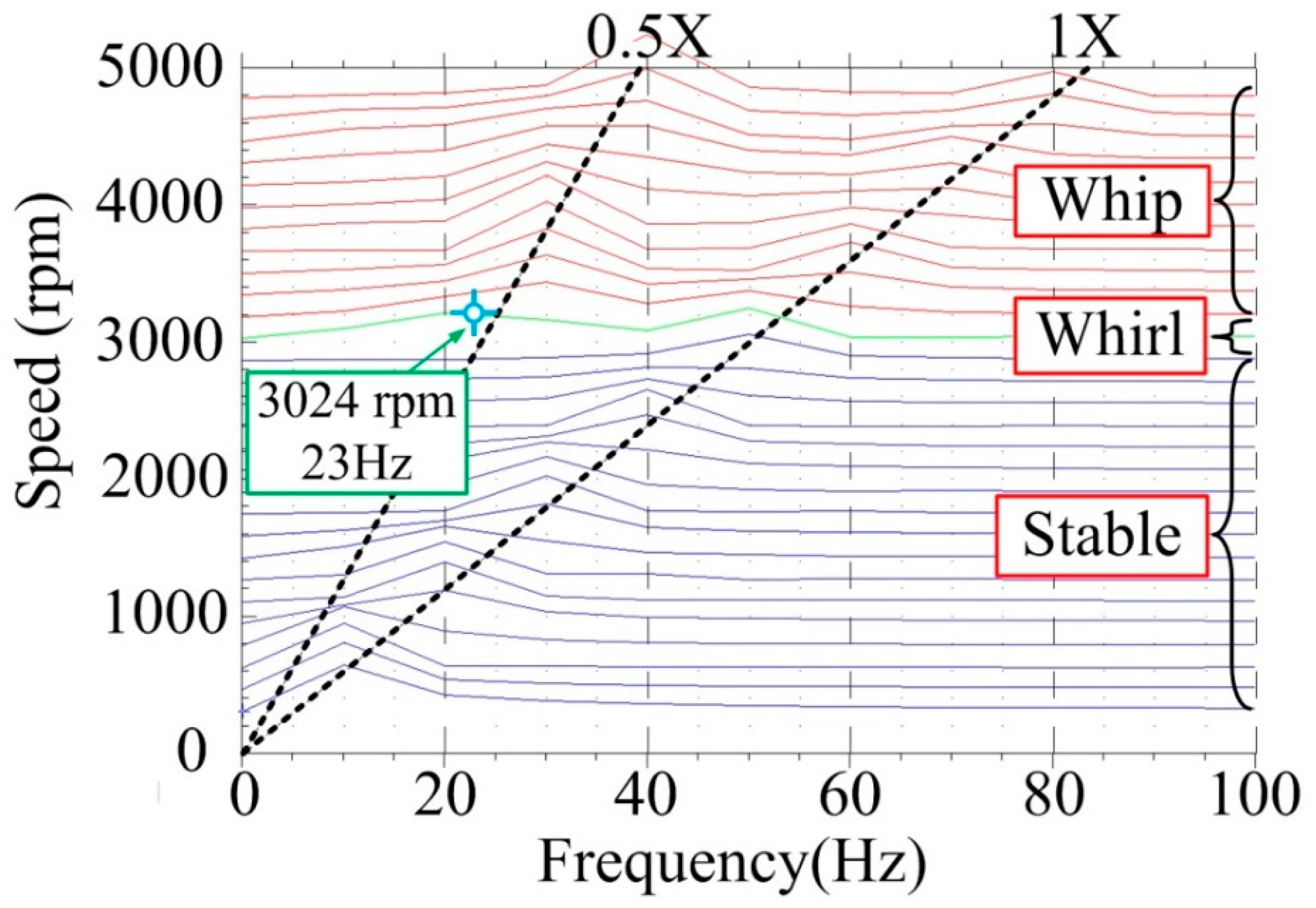
5.2. Oil Whirl and Whip Phenomena
Figure 6 shows the spectrum plots and full spectrum cascade plots of the oil bearings using ferrofluid as the lubricating oil without any magnetic field. The rotating speed is increasing at 1 Hz/s. If the signals of the two eddy current sensors installed next to bearing protection do not show the shaft impacts to the protective bearing, the motor will drive the shaft to 100 Hz. When the speed of the rotor system reaches the mechanical first balance resonance point, the vibration increases, thus, generating self–excited vibration. In
Figure 6, since the rotation speed is under 3024 rpm, the rotor–bearing system is actuated stably. However, when the rotation speed is 3024 rpm, self–excited vibration occurs. The vibration amount is higher than before 3024 rpm obviously. A whirl is generating and the rotor–bearing system is unstable. At the same time, the frequency of the whirl can be measured as 23 Hz by the machine 108 DAI. Thus, the precession speed can be calculated as 1380 rpm. The whip occurs when the rotation speed is 3184 rpm, and the lubricating fluid sub–synchronous frequency and vibration amplitude are proportional to the rotational speed.
From
Figure 6, we see that
Ωth is 3024 rpm revolutions. Then,
λ is obtained as
where 1380 is the precession speed.
By Formula (2), the original fluid stiffness
KB without external magnetic field can be calculated as
Thus, the value of the original fluid stiffness KB is 23,625 N/m.
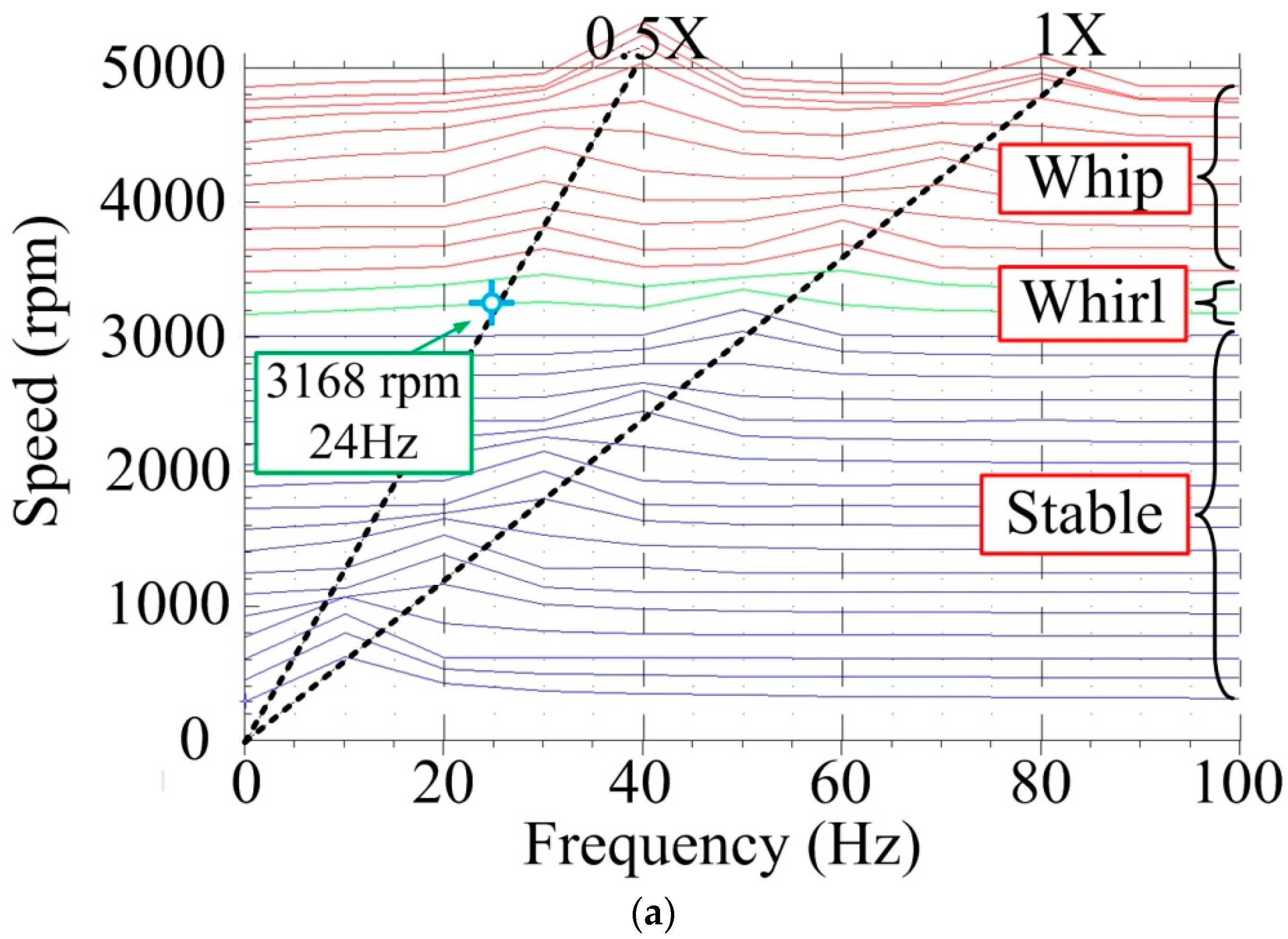
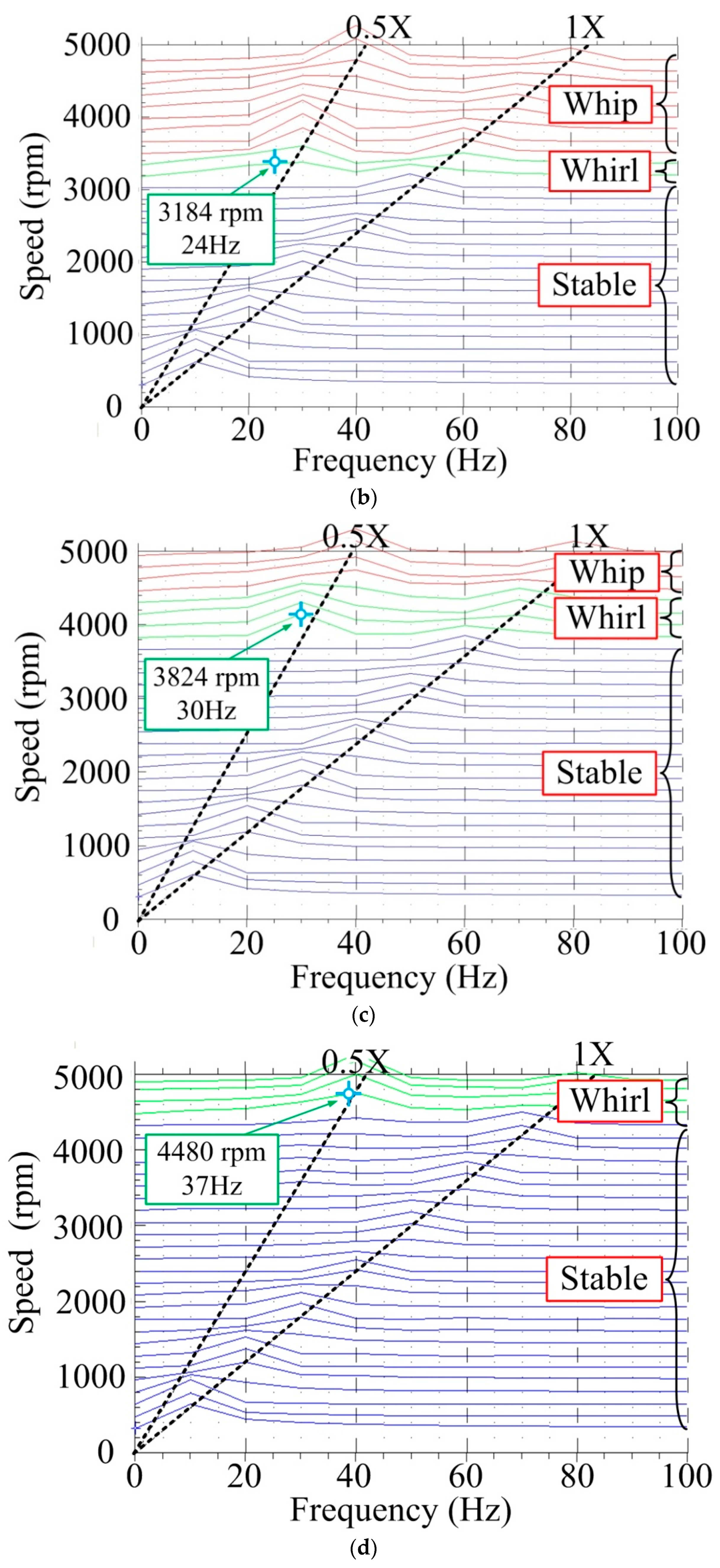
Regarding different magnetic field layouts, the magnetic fluid oil bearing is tested multiple times, and the magnets are placed in different positions under the bearing. According to the slots’ positions shown in
Figure 2, the recorded experimental data are (a) three magnets are placed in positions No. 3, 5, and 7; (b) five magnets are placed in positions 3–7; (c) seven magnets are placed in positions 2–8; and (d) eight magnets are inserted into the slots. Magnets 1, 3, 5, and 7 are set as north poles toward the center of the bearing and magnets 2, 4, 6, and 8 are set as south poles toward the center of the bearing. The threshold of instability is distinguished according to the full spectrum cascade plots of
Figure 7. The whirl occurs when the rotational speeds are 3168, 3184, 3824, and 4480 rpm, and the whip speeds are 3520, 3520, 4480, and 5268 rpm for the four cases. The experimental results show that if the magnetic field is just applied under the horizontal line of the bearing, the oil spin instability threshold risings are few with cases (a) and (b), which increase to about 144 rpm and 164 rpm; if the magnetic field is set around the bearing, the threshold risings are obvious with cases (c) and (d), which increase to about 800 rpm and 1456 rpm. The threshold risings expressed as percentages from cases (a) to (d) are 4.8%, 5.4%, 26.5%, and 48.1%, respectively.
The final step is to determine the stiffness increment of the magnetic fluid under magnetic field Km.
According to
Figure 7, the average velocity
λ for the four cases can be calculated as follows:
Using Formula (2), the magnetic fluid stiffness
K under the external magnetic field is obtained.
Therefore, K3 = 25,770 N/m; K5 = 25,802 N/m; K7 = 40,240 N/m; and K8 = 61,263 N/m.
The magnetic fluid stiffness under external magnetic field can be regarded as the sum of the magnetic fluid stiffness,
KB, without an external magnetic field and the magnetic fluid stiffness increment,
Km, which is the increased stiffness as the external magnetic field is applied to the system. That is, the stiffness can be expressed as
Therefore, under the effect of different external magnetic fields, the magnetic fluid stiffness increments are Km3 = 2145 N/m; Km5 = 2177 N/m; Km7 = 16,615 N/m; and Km8 = 37,638 N/m; or expressed as a percentage of 9.2%, 9.4%, 71.4%, and 161.8%, respectively.
It is obvious that the stiffness of magnetic field will increase as the external magnetic field is applied to the system. The arrangement of the types of magnets will affect the magnitudes of increment stiffness. Magnets set around the bearing can promote fluid rigidity to a higher magnitude. Thus, the oil spin instability threshold is also promoted to a higher speed by this arrangement.

 ,
, 


