Effect of Cavity Vacuum Pressure Diminution on Thermal Performance of Triple Vacuum Glazing


1
Centre for Advanced Materials, School of Engineering, London South Bank University, 103 Borough Road, London SE1 0AA, UK
2
Centre for Engineering Science and Advanced Systems, School of Engineering and Sustainable Development, De Montfort University, The Gateway, Leicester LU1 9BH, UK
*
Author to whom correspondence should be addressed.
Appl. Sci. 2018, 8(9), 1705; https://0-doi-org.brum.beds.ac.uk/10.3390/app8091705
Submission received: 22 August 2018
/
Revised: 10 September 2018
/
Accepted: 15 September 2018
/
Published: 19 September 2018
(This article belongs to the Special Issue Zero-Energy Buildings)
Abstract
:Featured Application
Triple Vacuum glazing is regarded as a smart window technology and a robust solution of retrofitting it to existing buildings for the reduction of demand side carbon emissions and improving the energy efficiency of buildings.
Abstract
Long-term durability of the vacuum edge seal plays a significant part in retrofitting triple vacuum glazing (TVG) to existing buildings in achieving progress towards a zero-energy building (ZEB) target. Vacuum pressure decrement with respect to time between panes affects the thermal efficiency of TVG. This study reports a 3D finite element model, with validated mathematical methods and comparison, for the assessment of the influence of vacuum pressure diminution on the thermal transmittance (U value) of TVG. The centre-of-pane and total U values of TVG are calculated to be 0.28 Wm−2 K−1 and 0.94 Wm−2 K−1 at the cavity vacuum pressure of 0.001 Pa. The results suggest that a rise in cavity pressure from 0.001 Pa to 100 kPa increases the centre-of-pane and total U values from 0.28 Wm−2 K−1 and 0.94 Wm−2 K−1 to 2.4 Wm−2 K−1 and 2.58 Wm−2 K−1, respectively. The temperature descent on the surfaces of TVG between hot and cold sides increases by decreasing the cavity vacuum pressure from 50 kPa to 0.001 Pa. Nonevaporable getters will maintain the cavity vacuum pressure of 0.001 Pa for over 20 years of life span in the cavity of 10-mm wide edge-sealed triple vacuum glazing, and enable the long-term durability of TVG.
1. Introduction
Climate change is a global challenge due to an increase of average global annual temperature of 0.99 °C, with CO2 levels reaching 400 ppm, breaking the 1950s’ level threshold of 300 ppm [1]. In buildings, the thermal transmittance (U value) is the combination of thermal conductance (i.e., the rate of heat flow between the higher-temperature area and lower-temperature area) and the thermal transfer coefficients. The total U value accounts for the effect of frames and edges, and the centre-of-pane U values do not account for the aforementioned effects. Vacuum insulation as a retrofit solution to existing buildings plays a momentous role in the reduction of carbon emissions and bringing our building sector towards a zero-energy building (ZEB) target [2], because buildings are accountable for at least 30% of the overall global final energy consumed [3,4]. Although a number of retrofitting measures to improve building insulation have already made the building sector more energy-efficient [5], it requires advanced technologies to bring the building sector towards a ZEB target. Triple vacuum glazing (TVG) has the ability to curtail heat flow between the warm side and cold side of a window, i.e., to provide preeminent thermal insulation, so-called thermal transmittance (U value) [6]. TVG consists of three panes of 4 mm thick glass, with an evacuated gap 0.13 mm high, separated by 0.13 mm high and 0.3 mm diameter stainless-steel support pillars. TVG edges are sealed with airtight material such as solder glass, indium alloy, or Cerasolzer CS186. The reason TVG has the potential for retrofitting to existing buildings is because its U value is less than 0.5 Wm−2 K−1, compared to triple air-filled glazing, which has a U value of 2.8 Wm−2 K−1. It also would allow increasing the window-to-wall area ratios because of its U value being closer to that of cavity wall insulation. Nevertheless, TVG has associated challenges; this paper presents the findings of the effects of diminution of vacuum pressure on the U value. The U value of TVG primarily depends on the thickness of the glass panes, vacuum pressure in the space between the glass panes, emissivity of the coatings on the glass panes, frame, and type of spacers that separate the panes of glass and type of window frame. The total U value consists of the influence of the frame and the area of the edge seal. The edge seal area is dependent on the width and the type of edge-sealing material. The airtight edge seal of a TVG must be able to perpetuate a vacuum pressure below 0.1 Pa for quelling gaseous heat conduction for long-term duration [7]. Benson et al. [8] investigated laser technology in a vacuum chamber to seal the edges of two glass panes. This achieved an airtight edge seal, but the cavity vacuum pressure was not below 0.1 Pa because the laser seal instigated particles such as moisture and notorious gases [9]. The first successful fabrication method of double vacuum glazing (i.e., an evacuated cavity between two panes of glass) relied on a lead-based solder glass material sealed at around 450 °C (it was recognised as a high-temperature sealing method because of its melting temperature) [10,11]. This method achieved a centre-of-pane U value of 0.8 Wm−2 K−1 and progressed to the commercial scale with a trade name of SPACIA. The problems with the high-temperature method of sealing are: the degradation of soft (low emissivity) coatings, meaning only hard coatings can be used [12]; and if using annealed glass, then loss of toughness, and requirement of higher amounts of heat energy for the construction. Investigations on a low-temperature solder glass material showed a hermetic edge seal, but durability was a problem due to the absorption of moisture [9]. The second successful fabrication method of double vacuum glazing used indium or an indium alloy, which was sealed in a low-temperature process, at about 160 °C. It required a secondary adhesive seal to prevent moisture access [13]. A low-temperature sealing process enables the use of low-emittance soft coatings, reducing radiative heat transfer between glass panes, and annealed glass allows to increase support pillar spacing, reducing conductive heat transfer [14]. The problem with the low-temperature fabrication method is the use of semiprecious indium alloys. It is a hindrance in advancing indium-sealed vacuum glazing at a commercial level [15]. Recently, a new low-temperature composite material and method of fabrication were reported by Memon et al. [16], in which the CS-186 type of Cerasolzer and steel-reinforced epoxy resin [17] were used for the development of composite edge-sealed triple vacuum glazing.
Despite the aforementioned successful constructions of double and triple vacuum glazing, there is always an uncertainty of the degradation/leakage of the cavity vacuum pressure. It is also pertinent that during the evacuation process or after sealing the pump-out tube of the TVG, there is a propensity of some gas molecules remaining in the cavity to react when exposed to sunlight and/or under extreme climate conditions for longer time periods due to the production of carbon monoxide inside the cavity that degrades the vacuum layer. It is obvious that TVG is exposed to sunlight and thus must be designed to withstand different climates and temperatures in order to avoid degradation of the vacuum. The heat conductance and internal pressure due to ageing (for over 250 days) of a vacuum glazing, with a temperature increased from ambient (21 °C) to 150 °C, was reported by Turner and Collins in 1997 [18]. It showed that both pressure inside the cavity and heat conductance rose upon heating. It identified that the increase in the thermal conductance from the glass bulk due to the water vapour evolved into the gap was negligible; it was less than 0.1 Wm−2 K−1 over a period of 25 years at 30 °C for the samples baked out at about 180 °C for 1 h. The result from mass spectroscopy showed that 95% of the total remaining gas on the internal glass surfaces is water vapour, whereas the remaining 5% includes H2, H2O, CO/N2, O2, and CO2. Fang et al. [19] investigated the extreme temperature cycling effect, for which the heat conductance at the centre-of-pane was found to be increased by about 10.2% (1.18 Wm−2 K−1 to 1.30 Wm−2 K−1) when the cavity vacuum pressure inside the vacuum glazing had increased from 0.1 Pa to 0.16 Pa. Ng et al. [20] conducted an investigation of gases evolved into the evacuated gaps in vacuum glazing, in which the samples of vacuum glazing were aged by exposing them to high temperatures and sunlight for a long period of time, and their internal pressure and the existing gases were studied using a vacuum gauge and a mass spectrometer, respectively. However, there is no literature available on the influence of cavity vacuum pressure diminution on triple vacuum glazing (TVG). Thus, this paper reports the effects of vacuum pressure on the thermal transmittance of TVG by developing a mathematical model using the finite element method in predicting their thermal performance.
This paper contributes to the new understanding of the effects of cavity vacuum pressure diminution on the thermal performance (heat-transfer characteristics) of triple vacuum glazing. In this paper, a 3D finite element method with details of the governing equations utilised and modelled heat-transfer mechanisms of the 10-mm wide edge-sealed triple vacuum glazing is reported. The influence of vacuum pressure diminution on the thermal transmittance (U value) of a triple vacuum glazing when the vacuum space (cavity) pressure decreases from 0.001 Pa (high vacuum pressure) to 101.321 kPa (atmospheric pressure) is investigated. This study enables the future prospects of improving the edge sealing of TVG and presenting significant findings on understanding how the diminution of vacuum pressure may affect the heat loss through TVG.
2. Materials and Methods
To analyse TVG thermal performance or the prediction of U values, a 3D finite element model was developed using a validated approach based on the boundary conditions. The U value was quantified with the boundary conditions of: Temperature, ; heat flux (surface) per unit area, ; heat flux (volumetric) per volume, ; heat-transfer convection (surface), , where the film coefficient and temperature (sink) ; and heat-transfer radiation, , where is the radiation constant and the value is absolute zero on the temperature scale used. The heat conduction occurred as a solid body in which the conductivity is subjected to the temperature, internal energy with effects of latent heat, and convection and radiation equations. According to Green and Naghdi [21], the energy balance approach used is stated in Equation (1), and with the Fourier law Equation (2), is acquired by applying the standard Galerkin spatial discretisation method.
where is the volume of the glazing components having: , area of the surface; r, the heat supplied externally per volume; , the density of the materials; , the material time rate of the internal energy; and , the heat flux per unit area. It is an adopted assumption that iterative solutions are disjoined in such a way that only , where is the temperature of the material. is the arbitrary differential field satiating the essential boundary conditions. The body is estimated geometrically with finite elements, so the temperature is interpolated as in Equation (3):
where TN are nodal temperatures. The Galerkin approach presumes , that the variation field is interpolated by the same functions as , and that is arbitrarily chosen. First- and second-order polynomials consist of 1D, 2D, and 3D for NN. With these interpolations, the variation of Equation (2) is rewritten as:
The 8-node brick in a second-order heat-transfer element method [22] used a numerical Gaussian integration rule, because by using this for the TVG, a smooth solution can be achieved.
The heat transfer mechanisms through conduction elements are proposed and are based on the combination of piecewise quadratic interpolations of TN via the breadth of the element. The isoparametric interpolation functions for the element associated with the heat-conduction reference surface are utilised. TN are coupled at a set of points via the breadth at each node of the element (nodes ). For computational numerical integration of the finite element equations, a 2 × 2 Gauss integration scheme with a 2 × 2 nodal integration scheme is used for the internal energy and specific heat term used for the quadrilateral element with a 3 × 3 Gauss integration method.
Let be individual TVG elements directing to the reference surface point of the element related with heat conduction, and measures the position through the thickness of the heat conduction object, such as the edge seal, glass panes, and support pillars, so that , where is the thickness of the element and z0 is the offset of the reference surface from the mid-surface. The position of any point in the element is given by Equation (5).
where is the locus and is the unit normal of a point in the reference surface. The interpolation of the temperature is written as in Equation (6):
where is a piecewise parabolic interpolation, is the interpolator in the reference surface, and are nodal temperature values (at node , point via the breadth). The thermal energy balance Equation (2) is now rewritten as Equation (7), which accounts for the heat conduction of each element with the approximate Jacobian matrix for the Newton method.
where is the correction to the temperature solution at time . The form of these terms for the elemental heat conduction, e.g., through the edge seal and support pillars, is obtained by introducing the interpolator and neglecting the change in area with respect to of surfaces parallel to the reference surface. The piecewise quadratic interpolation through the breadth of finite elements is represented by Equation (8).
where is a one-step operator for stabilising the heat-transfer processes and the elemental heat transfer through convection modelled with a nonsymmetric Jacobian matrix, thus both transient and steady-state capabilities are incorporated. The transient capability introduces a limit on the time increment; the time increment is adjusted to satisfy this limit. Equation (9) is matched to the work by Yu and Heinrich [23,24].
where is the temperature distribution; is the arbitrary variation field; is the fluid density; is the specific heat of the air molecules, which can then be reduced for the perfect vacuum; is the conductivity of the air molecules at a particular pressure; is the auxiliary heat distribution in the volume; is the surface heat distribution per volume where temperature is not prescribed ); is the outward normal to the surface; is the spatial position; and is time. Low-pressure air in the cavity will have isotropic conductivity, so that (where is a scalar and is the unit matrix). The boundary conditions are such that is coupled to and heat flux inflowing to the domain across the rest of the surface,, is associated by convection and/or radiation conditions and is expressed in Equation (10).
where is the heat flux linked to the conduction through the surface only, and any convection of energy across the surface is not included in . It makes negligible variance if the surface is part of a solid body (where is defined by heat transfer into the adjacent body), since then, the normal velocity (v.n.) into that body is equal to 0, due to no continuous fluid crossing the surface, and here is assumed as static conditions in a TVG.
The elemental heat transfer through radiation is dependent on the surfaces that are comprised of facets with radiation boundary conditions. In this 3D FEM, a facet is a face of a solid element of TVG and each facet is presumed to be isothermal, having unvarying emissivity. Cavity heat radiation elements, calculated through Abaqus, produce a series of matrices, since they couple the temperature degrees-of-freedom of every node on the cavity surface. Such a method of surface radiation is followed according to Holman [25] and Howell et al. [26]. Radiation flux density into a cavity facet stated in Equation (11) depends on the grey body radiation theory, in which the monochromatic emissivity of the facets is independent of the wavelength of propagation of the radiation and only nondirectional reflection is applied with the approximation of isothermal and isoemissive cavity facets.
where are the surface emissivities of facets , ; is the Stefan–Boltzmann constant; is the geometrical view factor matrix; are the temperatures of facets , ; is the value of absolute zero on the temperature scale being used; and is the Kronecker delta. Distinctively, in the blackbody radiation, where no reflection takes place, the addition of all emissivities is equal to one and Equation (11) is condensed to Equation (12).
The radiation flux is made up of finite element facets, which occurs when the heat is exchanged in a way that is dependent on view factors, which is a dimensionless factor between two elementary areas, and , satisfying the relation of Equation (13).
where is the gap between two areas and , are the angles between . The dimensionless view factor is a geometrical number, and for the validation of the accuracy of the calculations used in Equation (14), it is a result of the fact that all rays from facet i collide with other the surface j in an enclosed cavity.
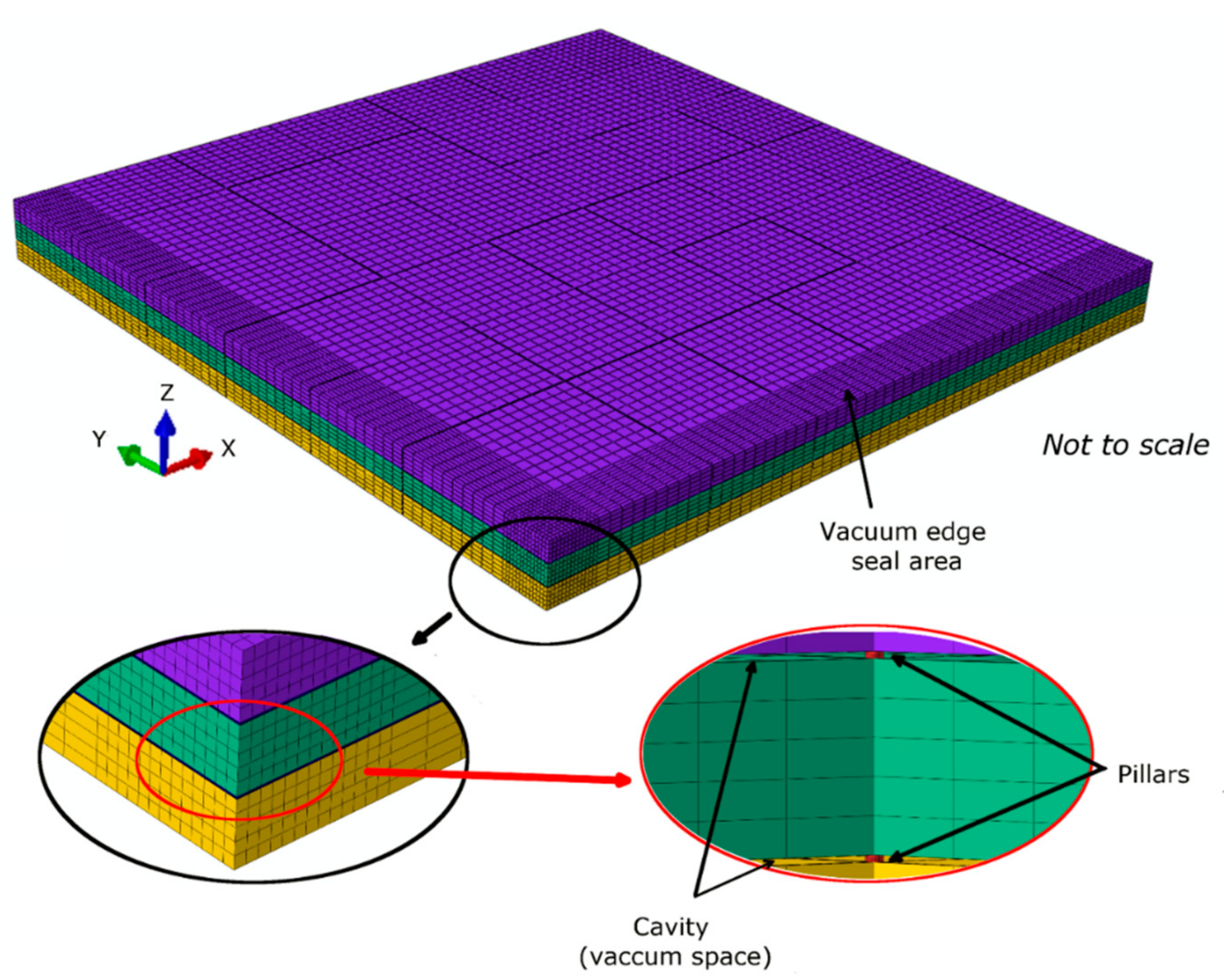
To reduce the computational time and due to symmetrical conditions, one quarter (150 mm × 150 mm) of the TVG size of 300 mm × 300 mm × 4 mm was simulated. The model was designed using an eight-node linear brick diffusion element, with a total of 174,100 elements and 204,226 nodes, used to model a quarter of the TVG as shown in Figure 1. The vacuum cavity is modelled as a material with thermal conductivity dynamically dependent on the air molecules and its mean free path as most of the thermal conduction occurs due to molecules adsorbed on the surfaces and/or left in the cavity of the vacuum gap. A 6 μm layer on the inner surface of the glass panes with the emissivity of tin oxide is the coating modelled for radiation heat-transfer simulations. The stainless-steel support pillars, modelled as a square with the side length of 1.78r, represented the same heat transfer as of the cylindrical type used; this approach was used by Fang et al. [27] and Zhao et al. [28]. A graded mesh with a higher number of elements in the pillars was employed to achieve adequate representation of the heat transfer [6,17]. An example of the finite element mesh employed is shown in Figure 1. A series of 15 convergence tests were performed to ensure that the density of the elements used was sufficient to predict the thermal performance with an accuracy of more than 97%. It is vital in the 3D finite element model to perform the simulation with repetitive results and confirm with the literature. In the convergence tests, the error found was less than 0.4% and found to be precisely repeatable. The material properties and parameters of the simulated triple vacuum glazing are listed in Table 1.
A thermal contact between glass interfaces with a cavity gap between them is specified by incorporating the gap conductance coefficient between two closely adjacent surfaces with small clearance (similar to glass surfaces separated by support pillars). Thermal gap conductance between two surfaces is represented by nodes 1 and 2 with temperatures and ( > ), and the clearance d between them is shown in Figure 2.
The gap heat transfer is defined by the summation of gaseous conductance heat transfer and radiation heat transfer between two adjacent surfaces, i.e., Equation (15).
where is the gap heat transfer, is the gas conductance heat transfer, and is the radiation heat transfer. The gas conductance heat transfer over a fixed gap clearance is given by Equation (16).
where is the conductance coefficient of the gas and and are the temperatures at nodes 1 and 2, respectively. Subroutine GAPCON can help to define the dependency of on different variables, including temperature, distance, and pressure between the bodies. In this study, it is used to define the as a function of pressure between the glass surfaces [22].
The radiation heat transfer () between two nodes in contact is given by Equation (17).
where is the Stefan–Boltzmann constant and and are the temperatures at nodes 1 and 2, respectively. The theoretical model of the thermal gap conductance is implemented into Abaqus using the user-defined GAPCON subroutine. When the GAPCON subroutine is called, it provides the pressure and temperatures and for the contacting nodes 1 and 2 on adjacent glass surfaces for defining the thermal gap conductance.
The thermal transmittance U value consists of the centre-of-pane and total glazing area values. The total glazing area contains the edge effects, whilst the centre-of-pane does not [30]. The ASTM [31] testing conditions are followed, in which the internal and external surface heat-transfer coefficients were set to 8.3 Wm−2 K−1 and 30 Wm−2 K−1, respectively [32], and the internal and external surface air temperatures were set to be at 21.1 °C and −17.8 °C, respectively. The glass surface-to-surface thermal transmittance of the total glazing and the centre-of-pane glazing is defined by Equations (18) and (19).
where and are the centre-of-pane and total internal surface thermal resistances, respectively, and and are the centre-of-pane and total external surface thermal resistances, respectively. and are the centre-of-pane and total average heat flux by conduction, convection, and radiation, simulated using Abaqus as per the preceding equations, respectively. Similarly, and are the calculated centre-of-pane internal and external average surface temperatures, respectively. and are the total internal and external average surface temperatures, respectively.
3. Results and Discussion
3.1. Thermal Performance Analysis of 10-mm Wide Edge-Sealed TVG
The and values of 0.28 Wm−2 K−1 and 0.94 Wm−2 K−1 were simulated for the triple vacuum glazing at the cavity vacuum pressure of 0.001 Pa, and the solar heat gain coefficient (G value) was predicted to be 0.7. A decrease of 15.15% in the value and 10.47% in the value compared with the results of Memon et al. [16] were found. Such decrement in the and values can be attributed to the fact that the secondary edge seal was not used in the current model and due to the integration of cavity thermal conductivity assigned to achieve 0.001 Pa (high vacuum pressure). The value of 0.2 Wm−2 K−1 was predicted by Manz et al. [14] for a TVG made with 6 mm, 4 mm, and 6 mm thick glass panes and four coated surfaces, each with the emissivity value of 0.03, whilst in the present case, all glass panes are 4 mm thick and have three SnO2-coated surfaces, each with emissivity of 0.15. By accounting for all parameters, the present model is in good agreement with Manz et al. [14], with an error of approximately 4.7%. In comparison to the results of Fang et al. [33], a value of 0.26 Wm−2 K−1 and value of 0.65 Wm−2 K−1, an increase of 7.14% in , and 30.85% increase in values obtained from the modelled TVG was found. Fang et al. [33] used a 500 mm × 500 mm size TVG with a 6 mm-wide edge seal and four coated surfaces each having emissivity of 0.03. One of the potential reasons for such an increase in the value obtained from the current model is linked to edge effects. A 10-mm wide edge seal is used in this study, as compared to 6 mm wide, to simulate the design fabricated by the author given elsewhere [16]. Glazing size, due to edge effects, also influences the total thermal transmittance; for a TVG with size of 500 mm × 500 mm, was calculated to be 38% greater than that of a 1 m × 1 m glazed area (Fang et al. [34]). The emissivity of the surface coatings used in this study is 0.15, as compared to that of 0.03 in the literature. A model with same sample size, surface emissivity, and seal materials’ properties developed to validate the method and results were in good agreement to those presented by Fang et al. [34], with an error of 6.3%.
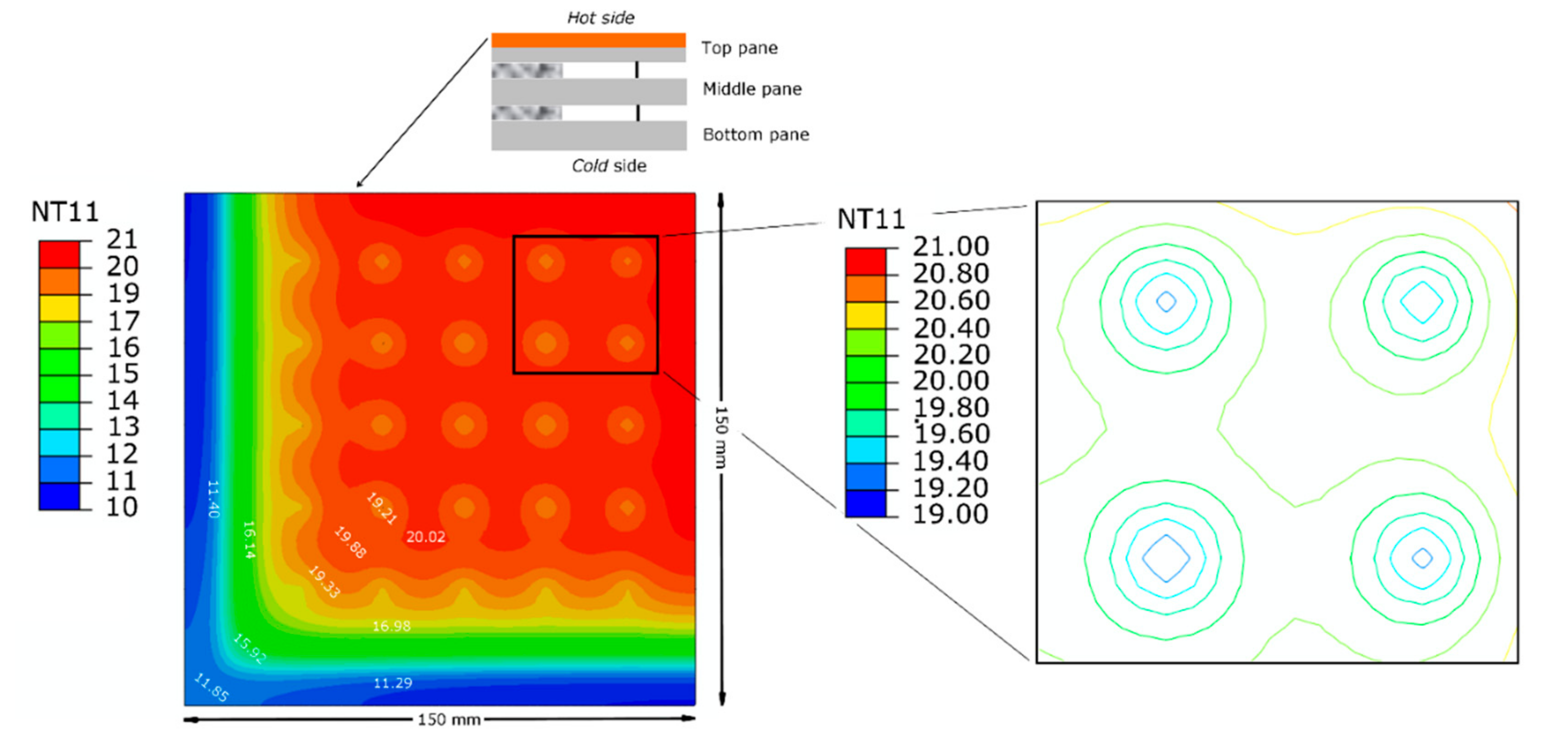
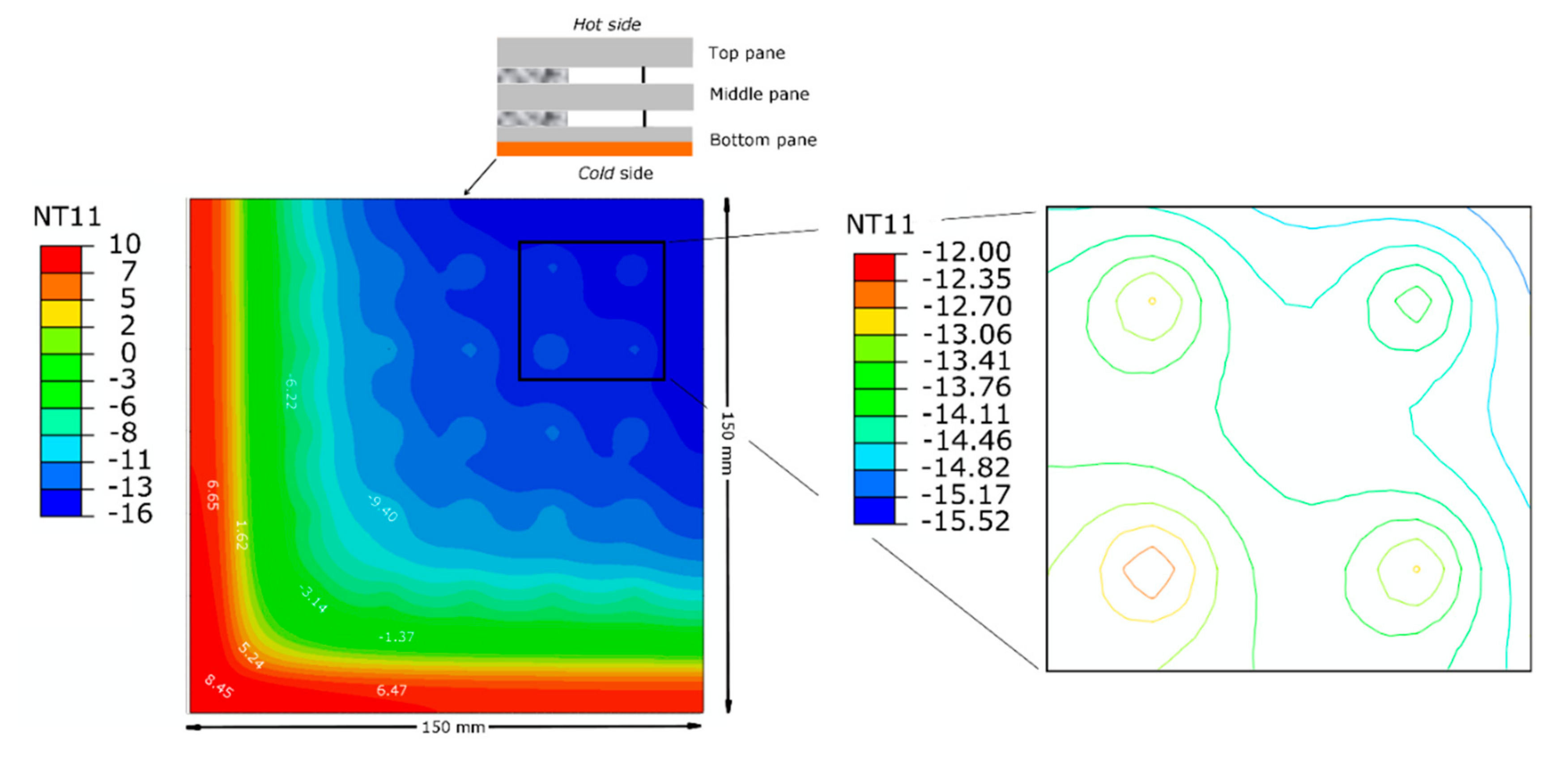
The isothermal temperature distribution of the simulated TVG for the cold-side, middle, and warm-side surfaces, as shown in Figure 3, Figure 4 and Figure 5, illustrate significant heat-transfer characteristics necessary in assessing the performance of TVG at high vacuum pressure, in which the heat flux from the warm side of the space in a building applied to the indoor glass surface, the thermal radiation between two inner glass surfaces, heat conduction via the edge seal and support pillars, and the heat flux from the outdoor (cold) surface of the glass to the outdoor ambient as per ASTM standard temperatures [35] are required. The average warm-side (indoor) and cold-side (outdoor) surface temperatures are simulated to be 19.22 °C and −9.44 °C for the total surface area, respectively, whilst being 20.14 °C and −14.13 °C for the centre-of-pane surface area, respectively.
Figure 3 shows the simulated warm-side isothermal temperature distribution of the surface of the TVG, showing the temperature dissimilarity from the edge area headed to the central area and around the support pillars in the central glazing area. The temperature difference between the heat conduction through the support pillars and radiative heat flow in the central high-vacuum area is predicted to be 1.4 °C.
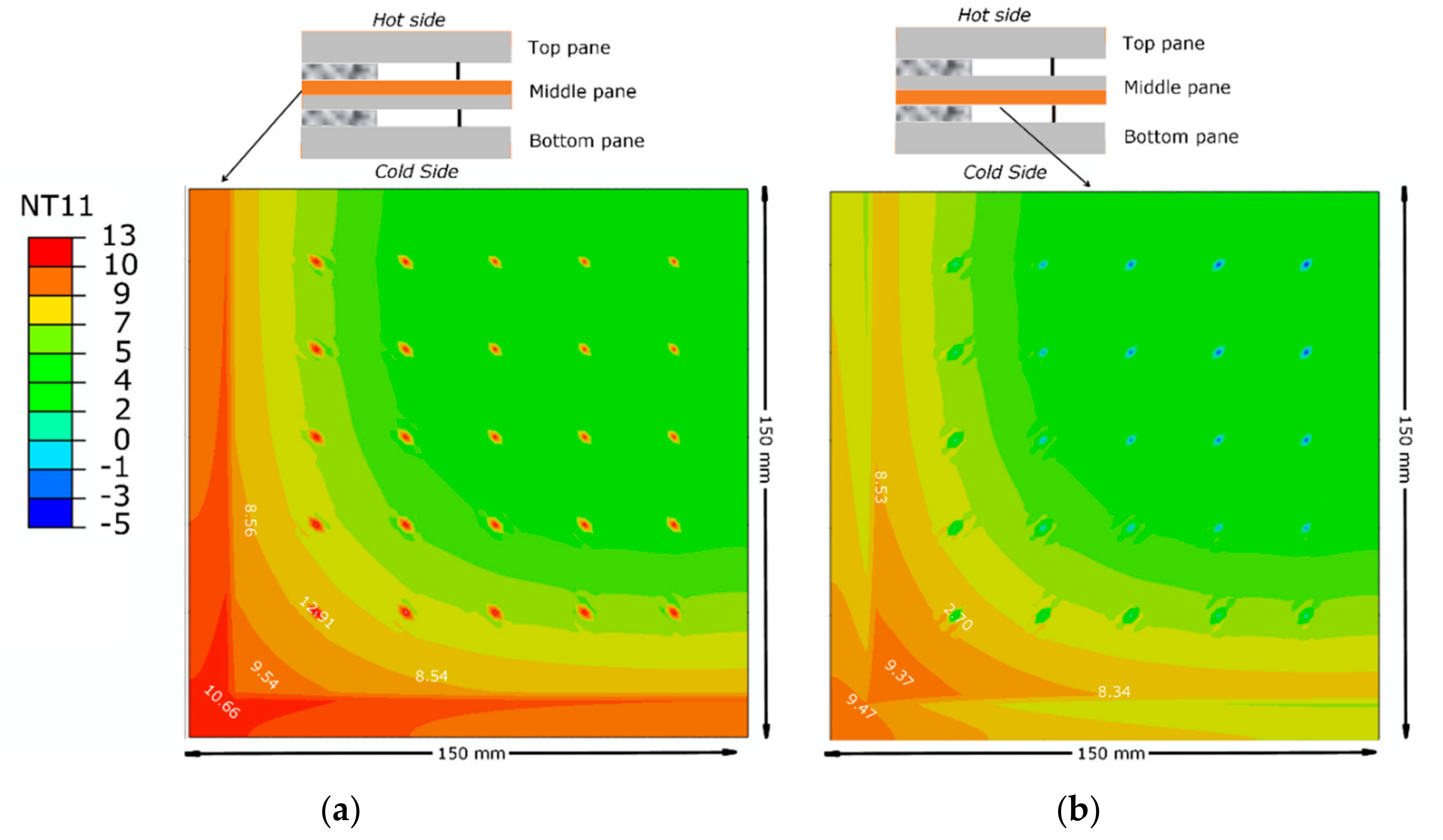
The isothermal temperature distribution for the middle-glass surface facing the warm side (Figure 4a) and cold-side (Figure 4b) of the TVG show the heat distribution from the edge area distributed to the central area of the one-quarter-portion crossing through the support pillars, in which the heat flow across the support pillars is larger than that over the vacuum area.
The simulated isotherms for the cold-side surface of the TVG, in which the heat distribution due to the edge seal and the support pillar array influences the thermal transmittance value, are shown in Figure 5. The variance in temperature was due to the pillar heat conductance and radiative heat flow over the central vacuum area, predicted to be 2.1 °C.
3.2. Effect of Vacuum Pressure Diminution on the Thermal Performance of TVG
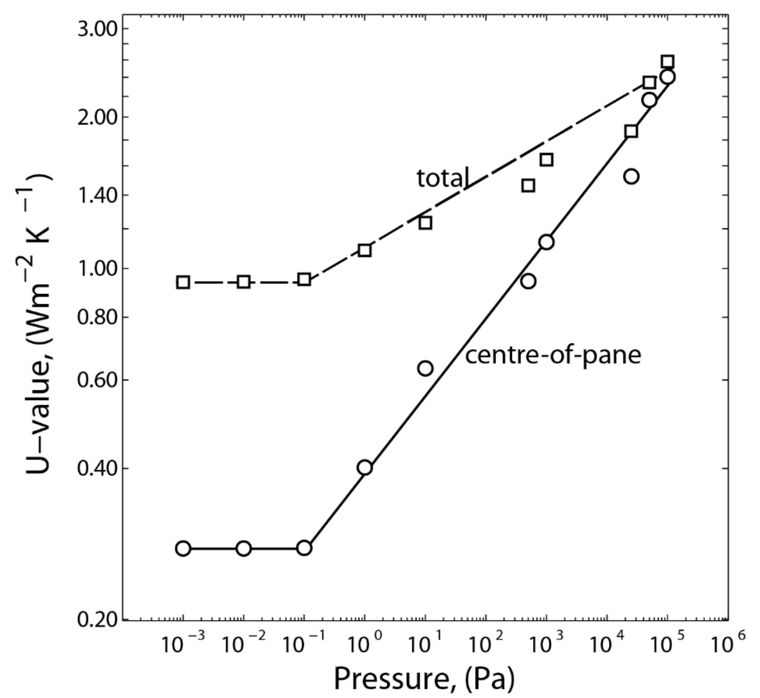
A vacuum insulation is a cavity, not an empty space between two glass panes, as there is no concept of the absolute emptiness in high-vacuum physics, but a reduced mass of atmospheric air. The density of air in a space determines the level of vacuum pressure [35]. This provides thermal insulation, because with a lower density of air, the mean free path between air molecules is enlarged to above 1000 m, which eventually lowers the heat-transfer path between the air molecules in a space. In TVG (the current study), the space between glass panes is sealed with a hermetic edge seal, i.e., Cerasolzer CS-186, and evacuated to high vacuum pressure 0.001 Pa, with the intention of lowering conductive and convective heat transfer to negligible values. However, the radiation heat transfer is curtailed using low-emittance SnO2 coatings. The influence of vacuum pressure decrement due to the vacuum edge seal is usually caused by either degradation due to adsorption of gaseous molecules, mechanical handling, and/or inconsistent making of the edge seal or the edge seal not being congruent. The FEM results, as shown in Figure 6, predict that when increasing the cavity pressure from 0.001 Pa to 100 kPa, the and values increased from 0.28 Wm−2 K−1 and 0.94 Wm−2 K−1 to 2.4 Wm−2 K−1 and 2.58 Wm−2 K−1, respectively. However, due to the ageing process, the TVG may lose the vacuum pressure and this would affect its thermal performance, mainly because of the water vapours evolved from the glass surfaces during the fabrication which had not desorbed from the glass surfaces and remained in the vacuum space. Thus, the use of nonevaporable getters sealed under specific temperature cycles is necessary. This is because water molecules that were outgassed during high-temperature thermal ageing and readsorbed onto the glass surfaces at room temperatures can ruin the stability of the internal vacuum pressure, unless nonevaporable getters are used.
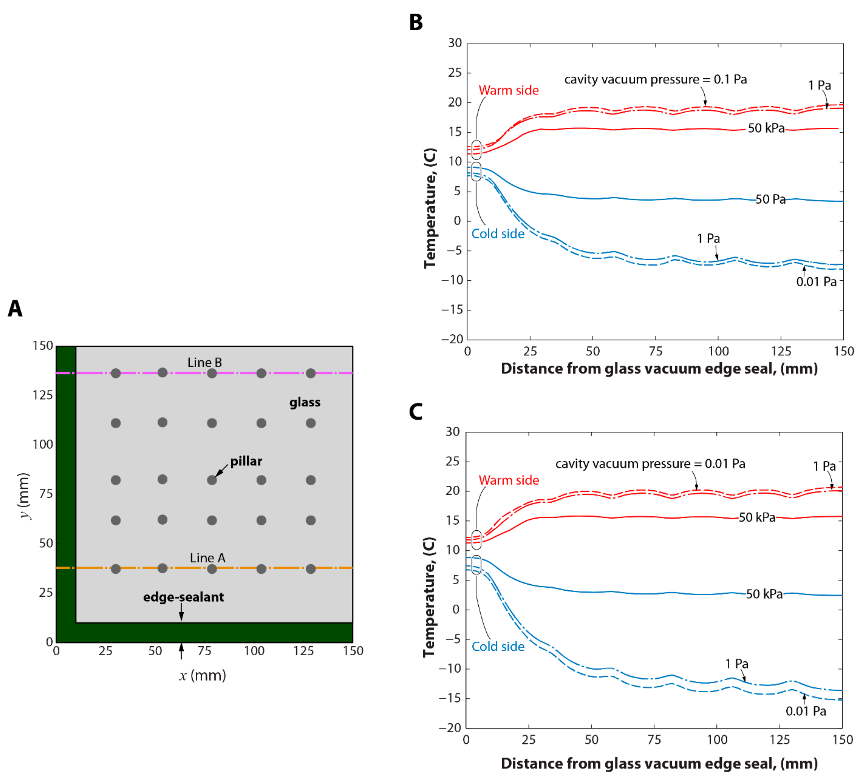
Figure 7 shows the surface temperature contours for the hot and cold sides at the cavity pressures of 0.001 Pa, 1 Pa, and 50 kPa, spreading from the vacuum edge seal to the centre-of-pane of one quarter of the TVG along Line B and Line A (as illustrated in Figure 7a). It shows that the temperature gradients between the hot and cold sides increase by decreasing the cavity vacuum pressure from 50 kPa to 0.001 Pa. A reduction in cavity vacuum pressure affects the surface heat transfer quite significantly. However, the temperature gradients on the cold side are larger than on the warm side, due to the direction of the heat flow on the hot side dissipating heat through the edge seal and influencing towards the centre-of-pane area, consequently developing edge effects that spread up to distances of 38 mm and 70 mm from the edge to the centre-of-pane on the hot and cold side surfaces along Line A (which is nearer to the edge corners). Nevertheless, at 50 kPa, the edge effects to the centre-of-pane are smaller along line A (about 26 mm and 30 mm on the hot and cold sides, respectively) because of the diminution of the vacuum pressure affecting temperature gradients. Line B is approximately 130 mm away from the horizontal axis of the TVG quarter; it shows that the edge effects reduce when moving away from the edge corners. When comparing the surface temperature contours along Line A and Line B on the hot and cold sides, the temperature gradients on Line B was increased compared to Line A at the cavity vacuum pressures of 0.001 Pa and 1.0 Pa. By reducing the width of the edge seal, further reduction to the edge effects were achievable. A negligible difference in temperature gradients was predicted at the cavity vacuum pressure of 50 kPa of the TVG, which effectively increases the heat transmission with less influence of the edge seal.
4. Conclusions
Long-term durability of the vacuum edge seal has been the paramount requirement, specifically, in the evolution of TVG for the potential retrofitting to existing buildings in achieving progress towards a ZEB (Zero energy Building) target. For this, it has long been estimated, but never been reported quantitatively, the influence of the diminution of vacuum pressure on the thermal performance of TVG. In this study, a 3D finite element model with validated mathematical methods was utilised for the assessment of the influence of vacuum pressure diminution on the thermal performance of a 10-mm wide edge-sealed triple vacuum glazing. The finite element model was validated with mathematical methods and by comparing the results with those in the literature. and values calculated from the current model were in good agreement with those measured by Manz et al. [14] and Fang et al. [33]. The and values in the FEM model of TVG were predicted to be 0.28 Wm−2 K−1 and 0.94 Wm−2 K−1 at the cavity vacuum pressure of 0.001 Pa. The results suggest that when increasing the cavity pressure from 0.01 Pa to 100 kPa, the and values increased from 0.28 Wm−2 K−1 and 0.94 Wm−2 K−1 to 2.4 Wm−2 K−1 and 2.58 Wm−2 K−1, respectively. This indicates that when a decrement of vacuum pressure occurs, it will make the thermal performance inadequate, and the use of nonevaporable getters would resolve the degradation issue. It is concluded that the glass surface temperature gradients between the hot and cold sides increases by decreasing the cavity vacuum pressure from 50 kPa to 0.001 Pa. The influence of cavity vacuum pressure decrement affects the surface heat transfer quite significantly, and the edge effects spread up to distances of 38 mm and 70 mm from the edge to the centre-of-pane on the hot- and cold-side surfaces when contoured along Line A, which is nearer to the edge corners. The edge effects reduce when moving away from the specimen edge. By reducing the width of the edge seal, the edge effects could be further minimised. A negligible difference in temperature gradients was predicted at the cavity vacuum pressure of 50 kPa of the TVG, which effectively increases the heat transmission with less influence of the edge seal. With 50 kPa pressure, the edge effects to the centre-of-pane are smaller along Line A (about 26 mm and 30 mm on the hot and cold sides, respectively) because of the diminution of the vacuum pressure affecting temperature gradients. The ageing and high-temperature exposure issues are important because of the degradation of the vacuum pressure inside the cavity due to ineffective evacuation of the cavity, improper pump-out sealing, and the remaining residues of air or moisture molecules in the cavity (that boost the production of CO, CO2, H2O, and/or H2 inside the cavity). Such issues could be solved by utilising nonevaporable getters that require activation temperatures of more than 400 °C and/or preactivated combo-getters. It is recommended that without getters, the stability of vacuum pressure of 0.001 Pa for over 20 years of life span in the cavity of 10-mm wide edge-sealed triple vacuum glazing is difficult to achieve even under a controlled environment.
Author Contributions
S.M.: conceptualization, methodology, mathematical modelling, and writing of the paper; F.F., S.M., and K.K: software, validation, formal analysis, and review and editing.
Funding
This research received no external funding and The APC was funded by London South Bank University.
Acknowledgments
This work supported by the self-initiated research collaboration between London South Bank University, UK, and De Montfort University, UK. Authors would like to thank the reviewers and editors for their suggestions.
Conflicts of Interest
The authors declare no conflict of interest.
References
- Hansen, J.; Makiko, S. Regional climate change and national responsibilities. Environ. Res. Lett. 2016, 11, 034009. [Google Scholar] [CrossRef] [Green Version]
- Yaddanapudi, H.S.; Hickerson, N.; Shrikant, S.; Tiwari, A. Fabrication and characterization of transparent wood for next generation smart building applications. Vacuum 2017, 146, 649–654. [Google Scholar] [CrossRef]
- Memon, S.; Eames, P.C. Solar Energy Gain and Space-Heating Energy Supply Analyses for Solid-Wall Dwelling Retrofitted with the Experimentally Achievable U-value of Novel Triple Vacuum Glazing. J Daylight. 2017, 4, 15–25. [Google Scholar] [CrossRef] [Green Version]
- Memon, S.; Eames, P.C. Predicting the solar energy and space-heating energy performance for solid-wall detached house retrofitted with the composite edge-sealed triple vacuum glazing. Energy Procedia 2017, 122, 565–570. [Google Scholar] [CrossRef]
- Memon, S. Analysing the potential of retrofitting ultra-low heat loss triple vacuum glazed windows to an existing UK solid wall dwelling. Int. J. Renew. Energy Dev. 2014, 3, 161–174. [Google Scholar] [CrossRef]
- Memon, S. Design, Fabrication and Performance Analysis of Vacuum Glazing Units Fabricated with Low and High Temperature Hermetic Glass Edge Sealing Materials. Ph.D. Thesis, Loughborough University, Loughborough, UK, 2013. [Google Scholar]
- Fang, Y.; Hyde, T.J.; Arya, F.; Hewitt, N.; Eames, P.C.; Norton, B.; Miller, S. Indium alloy-sealed vacuum glazing development and context. Renew. Sustain. Energ. Rev. 2014, 37, 480–501. [Google Scholar] [CrossRef]
- Benson, D.K.; Tracy, C.E. Evacuated window glazings for energy efficient buildings. In Proceedings of the Optical Materials Technology for Energy Efficiency and Solar Energy Conversion IV, San Diego, CA, USA, 20–22 August 1985; pp. 250–256. [Google Scholar] [CrossRef]
- Eames, P.C. Vacuum glazing: Current performance and future prospects. Vacuum 2008, 82, 717–722. [Google Scholar] [CrossRef]
- Robinson, S.J.; Collins, R.E. Evacuated windows-theory and practice. In Proceedings of the ISES Solar World Congress, International Solar Energy Society, Kobe, Japan, 4–8 September 1989. [Google Scholar]
- Collins, R.E.; Tang, J.Z. Design Improvements to Vacuum Glazing. U.S. Patent 5,891,536, 6 April 1999. [Google Scholar]
- Griffiths, P.W.; Leo, M.D.; Cartwright, P.; Eames, P.C.; Yianoulis, P.; Leftheriotis, G.; Norton, B. Fabrication of evacuated glazing at low temperature. Sol. Energy 1998, 63, 243–249. [Google Scholar] [CrossRef]
- Fang, Y.; Eames, P.C.; Hyde, T.J.; Norton, B. Complex multimaterial insulating frames for windows with evacuated glazing. Sol. Energy 2005, 79, 245–261. [Google Scholar] [CrossRef]
- Manz, H.; Brunner, S.; Wullschleger, L. Triple vacuum glazing: Heat transfer and basic mechanical design constraints. Sol. Energy 2006, 80, 1632–1642. [Google Scholar] [CrossRef]
- Memon, S. Investigating energy saving performance interdependencies with retrofit triple vacuum glazing for use in UK dwelling with solid walls. In Proceedings of the Sustainable Development on Building and Environment: The 7th International Conference, Reading, UK, 1 July 2015; ISBN 13-978-0993120701. [Google Scholar]
- Memon, S.; Farukh, F.; Eames, P.C.; Silberschmidt, V.V. A new low-temperature hermetic composite edge seal for the fabrication of triple vacuum glazing. Vacuum 2015, 120, 73–82. [Google Scholar] [CrossRef] [Green Version]
- Memon, S. Experimental measurement of hermetic edge seal’s thermal conductivity for the thermal transmittance prediction of triple vacuum glazing. Case Stud. Therm. Eng. 2017, 10, 169–178. [Google Scholar] [CrossRef]
- Turner, G.M.; Collins, R.E. Measurement of heat flow through vacuum glazing at elevated temperature. Int. J. Heat Mass Transf. 1997, 40, 1437–1446. [Google Scholar] [CrossRef]
- Fang, Y.; Hyde, T.; Eames, P.C.; Hewitt, N. Theoretical and experimental analysis of the vacuum pressure in a vacuum glazing after extreme thermal cycling. Sol. Energy 2009, 83, 1723–1730. [Google Scholar] [CrossRef]
- Ng, N.; Collins, R.E.; So, L. Thermal and optical evolution of gas in vacuum glazing. Mater. Sci. Eng. B 2005, 119, 258–264. [Google Scholar] [CrossRef]
- Green, A.E.; Naghdi, P.M. A general theory of an elastic-plastic continuum. Arch. Ration. Mech. Anal. 1965, 18, 251–281. [Google Scholar] [CrossRef]
- Dassault Systèmes Simulia Corp. Abaqus Theory Guide; Dassault Systèmes Simulia Corp.: Providence, RI, USA, 2014. [Google Scholar]
- Yu, C.C.; Heinrich, J.C. Petrov-Galerkin methods for the time-dependent convective transport equation. Int. J. Numer. Methods Eng. 1986, 23, 883–901. [Google Scholar] [CrossRef]
- Yu, C.C.; Heinrich, J.C. Petrov—Galerkin method for multidimensional, time-dependent, convective-diffusion equations. Int. J. Numer. Methods Eng. 1987, 24, 2201–2215. [Google Scholar] [CrossRef]
- Holman, J.P. Heat Transfer; McGraw-Hill, Inc.: New York, NY, USA, 1990. [Google Scholar]
- Howell, J.R.; Menguc, M.P.; Siegel, R. Thermal Radiation Heat Transfer; CRC Press: Boca Raton, FL, USA, 2010; ISBN 9781498757744. [Google Scholar]
- Fang, Y.; Eames, P.C.; Norton, B.; Hyde, T.J. Experimental validation of a numerical model for heat transfer in vacuum glazing. Sol. Energy 2006, 80, 564–577. [Google Scholar] [CrossRef]
- Zhao, J.F.; Eames, P.C.; Hyde, T.J.; Fang, Y.; Wang, J. A modified pump-out technique used for fabrication of low temperature metal sealed vacuum glazing. Sol. Energy 2007, 81, 1072–1077. [Google Scholar] [CrossRef]
- Memon, S.; Eames, P.C. Heat load and solar gain prediction for solid wall dwellings retrofitted with triple vacuum glazing for selected window to wall area ratios. In Proceedings of the World Renewable Energy Forum, WREF, Denver, CO, USA, 13–17 May 2012; ASES: Denver, CO, USA, 2012; pp. 4636–4643. [Google Scholar]
- Collins, R.E.; Robinson, S.J. Evacuated glazing. Sol. Energy 1991, 47, 27–38. [Google Scholar] [CrossRef]
- Wang, J.; Eames, P.C.; Zhao, J.F.; Hyde, T.; Fang, Y. Stresses in vacuum glazing fabricated at low temperature. Sol. Energy Mater. Sol. Cells 2007, 91, 290–303. [Google Scholar] [CrossRef]
- Fang, Y.; Hyde, T.J.; Hewitt, N.; Eames, P.C.; Norton, B. Comparison of vacuum glazing thermal performance predicted using two and three dimensional models and their experimental validation. In Proceedings of the ASME 2008 Heat Transfer Summer Conference collocated with the Fluids Engineering, Energy Sustainability, and 3rd Energy Nanotechnology Conferences, Jacksonville, FL, USA, 10–14 August 2008; American Society of Mechanical Engineers: New York, NY, USA; pp. 133–139. [Google Scholar] [CrossRef]
- Fang, Y.; Hyde, T.J.; Hewitt, N. Predicted thermal performance of triple vacuum glazing. Sol. Energy 2010, 84, 2132–2139. [Google Scholar] [CrossRef]
- Fang, Y.; Hyde, T.J.; Arya, F.; Hewitt, N.; Wang, R.; Dai, Y. Enhancing the thermal performance of triple vacuum glazing with low-emittance coatings. Energy Build. 2015, 97, 186–195. [Google Scholar] [CrossRef] [Green Version]
- Memon, S.; Eames, P.C. Design, development and thermal performance analysis of ultra-low heat loss triple vacuum glazing. In Proceedings of the ISES solar world congress, Abu Dhabi, Arab, 29 October–2 November 2017; ISBN 978-3-981 465 9-7-6. [Google Scholar] [CrossRef]
Figure 1.
A quarter portion (size of 150 mm × 150 mm) of the 10-mm wide edge-sealed triple vacuum glazing showing the developed finite element mesh.
Figure 1.
A quarter portion (size of 150 mm × 150 mm) of the 10-mm wide edge-sealed triple vacuum glazing showing the developed finite element mesh.

Figure 2.
Thermal contact between two interfaces separated by a distance d.

Figure 3.
The isothermal temperature distribution (NT11 band) on the warm-side glass pane surface of the TVG, showing the temperature disparities (in °C) from the 10-mm wide edge-sealed area towards the centre-of-pane area due to the use of a 10-mm wide edge-seal.
Figure 3.
The isothermal temperature distribution (NT11 band) on the warm-side glass pane surface of the TVG, showing the temperature disparities (in °C) from the 10-mm wide edge-sealed area towards the centre-of-pane area due to the use of a 10-mm wide edge-seal.

Figure 4.
Isothermal temperature distribution on the middle-glass surface facing (a) the warm side and (b) cold side of the TVG, showing the temperature disparities in °C from the 10-mm wide edge-sealed area towards the centre-of-pane area.
Figure 4.
Isothermal temperature distribution on the middle-glass surface facing (a) the warm side and (b) cold side of the TVG, showing the temperature disparities in °C from the 10-mm wide edge-sealed area towards the centre-of-pane area.

Figure 5.
The isothermal temperature distribution (in °C) on the cold-side glass pane surface of the TVG, showing the temperature disparities from the 10-mm wide edge-sealed area towards the centre-of-pane area.
Figure 5.
The isothermal temperature distribution (in °C) on the cold-side glass pane surface of the TVG, showing the temperature disparities from the 10-mm wide edge-sealed area towards the centre-of-pane area.

Figure 6.
FEM-simulated results of the effect of vacuum pressure diminution between the two cavities, each 0.15 mm in height, on the degradation of the (circle dots) and (square dots) values of the TVG. The dashed and solid lines represent the trend line.
Figure 6.
FEM-simulated results of the effect of vacuum pressure diminution between the two cavities, each 0.15 mm in height, on the degradation of the (circle dots) and (square dots) values of the TVG. The dashed and solid lines represent the trend line.

Figure 7.
(A) The surface temperature contours for the hot and cold sides at the cavity pressures of 0.001 Pa, 1 Pa, and 50 kPa, spreading from the vacuum edge seal to the centre-of-pane of one-quarter of the TVG (B) along Line A and (C) Line B.
Figure 7.
(A) The surface temperature contours for the hot and cold sides at the cavity pressures of 0.001 Pa, 1 Pa, and 50 kPa, spreading from the vacuum edge seal to the centre-of-pane of one-quarter of the TVG (B) along Line A and (C) Line B.


Table 1.
Constructional boundary elements of the 10-mm wide edge-sealed TVG (Triple Vacuum Glazing).
Table 1.
Constructional boundary elements of the 10-mm wide edge-sealed TVG (Triple Vacuum Glazing).
| Type | Boundary | Parametric Condition |
|---|---|---|
| TVG dimensions | Pane (K glass) top | 0.3 m × 0.3 m |
| Pane (K glass) middle | 0.3 m × 0.3 m | |
| Pane (K glass) bottom | 0.3 m × 0.3 m | |
| Pane thickness | 4 mm | |
| Pilkington K glass pane | Heat conductivity | 1 Wm−1 K−1 [29] |
| Emittance | Low-emissivity coating (each pane) | 0.15/SnO2 |
| Edge seal | Alloy | Cerasolzer CS186 |
| Width | 10 mm | |
| Heat conductivity | 46.49 Wm−1 K−1 * | |
| Support pillar | Alloy | Stainless steel 304 |
| Diameter | 0.3 mm | |
| Height | 0.15 mm | |
| Pillar separation | 24 mm | |
| Heat conductivity | 16.2 Wm−1 K−1 [16] |
* Measurement of the thermal conductivity of Cerasolzer CS-186 reported by Memon [17].
© 2018 by the authors. Licensee MDPI, Basel, Switzerland. This article is an open access article distributed under the terms and conditions of the Creative Commons Attribution (CC BY) license (http://creativecommons.org/licenses/by/4.0/).
Share and Cite
MDPI and ACS Style
Memon, S.; Farukh, F.; Kandan, K. Effect of Cavity Vacuum Pressure Diminution on Thermal Performance of Triple Vacuum Glazing. Appl. Sci. 2018, 8, 1705. https://0-doi-org.brum.beds.ac.uk/10.3390/app8091705
AMA Style
Memon S, Farukh F, Kandan K. Effect of Cavity Vacuum Pressure Diminution on Thermal Performance of Triple Vacuum Glazing. Applied Sciences. 2018; 8(9):1705. https://0-doi-org.brum.beds.ac.uk/10.3390/app8091705
Chicago/Turabian StyleMemon, Saim, Farukh Farukh, and Karthikeyan Kandan. 2018. "Effect of Cavity Vacuum Pressure Diminution on Thermal Performance of Triple Vacuum Glazing" Applied Sciences 8, no. 9: 1705. https://0-doi-org.brum.beds.ac.uk/10.3390/app8091705
Note that from the first issue of 2016, this journal uses article numbers instead of page numbers. See further details here.