Recent Advances in Plasmonic Sensor-Based Fiber Optic Probes for Biological Applications

 ,
,
Abstract
:1. Introduction
2. Physics of Surface Plasmons
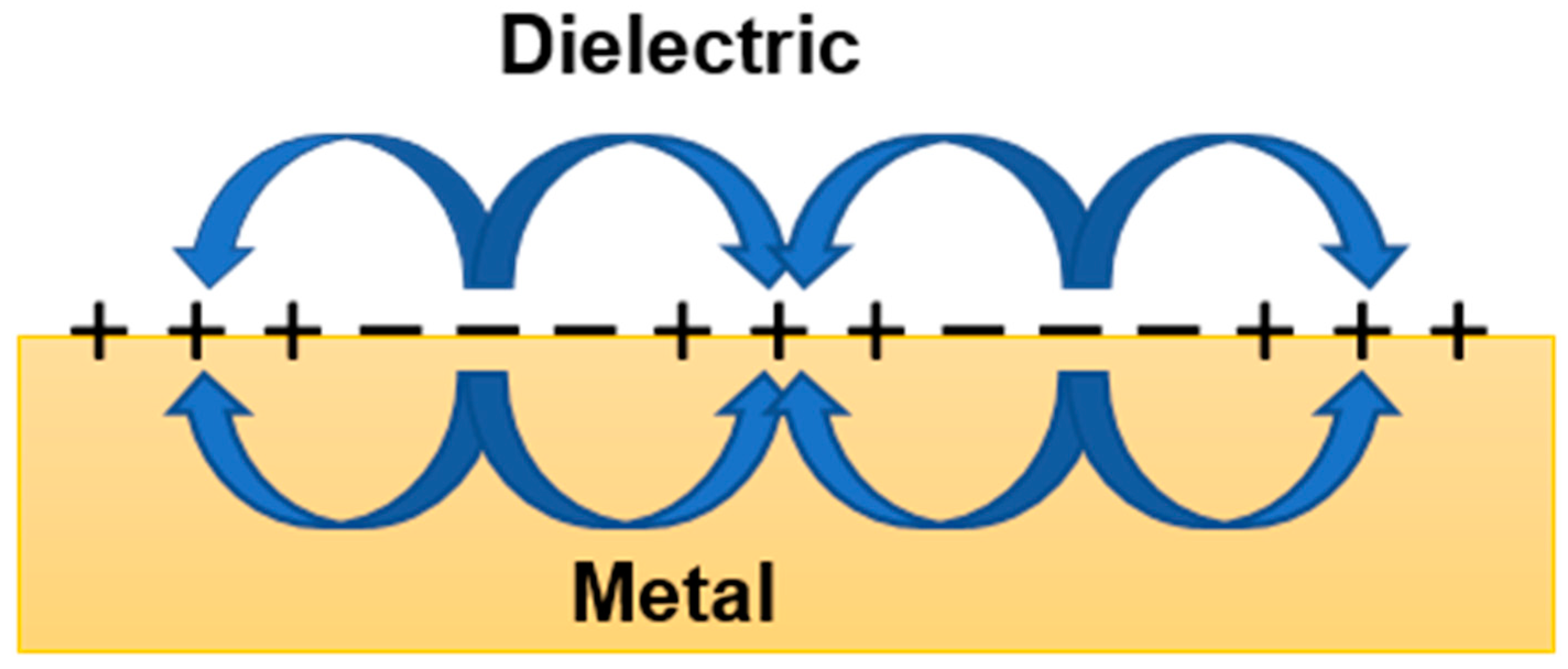
2.1. Surface Plasmon Polaritons
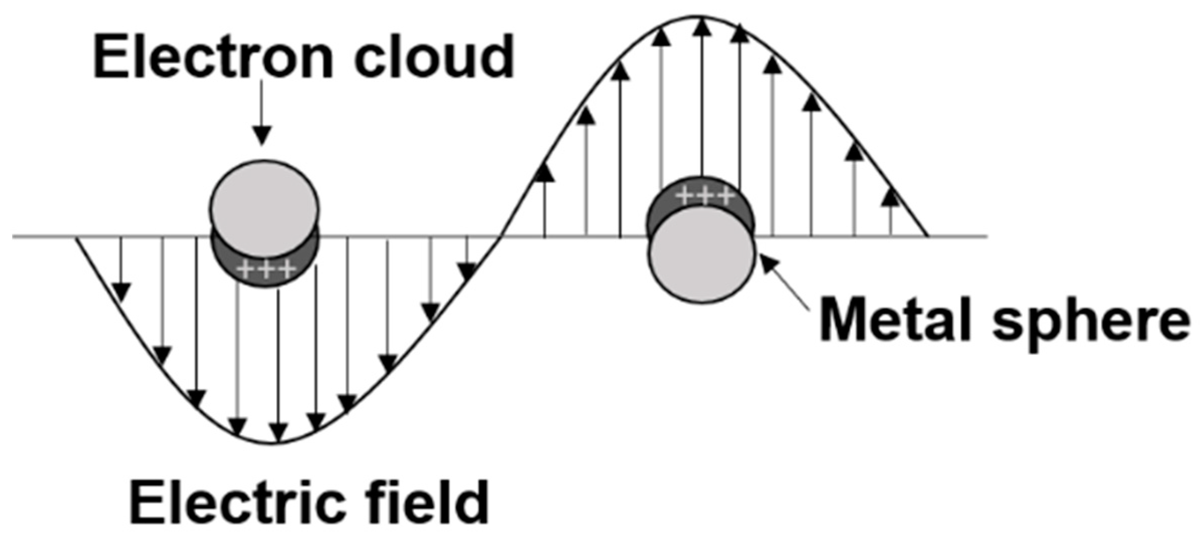
2.2. Localized Surface Plasmon Polaritons
3. Resonance Conditions
3.1. Surface Plasmon Resonance
3.2. Localized Surface Plasmon Resonance
4. Theoretical Framework
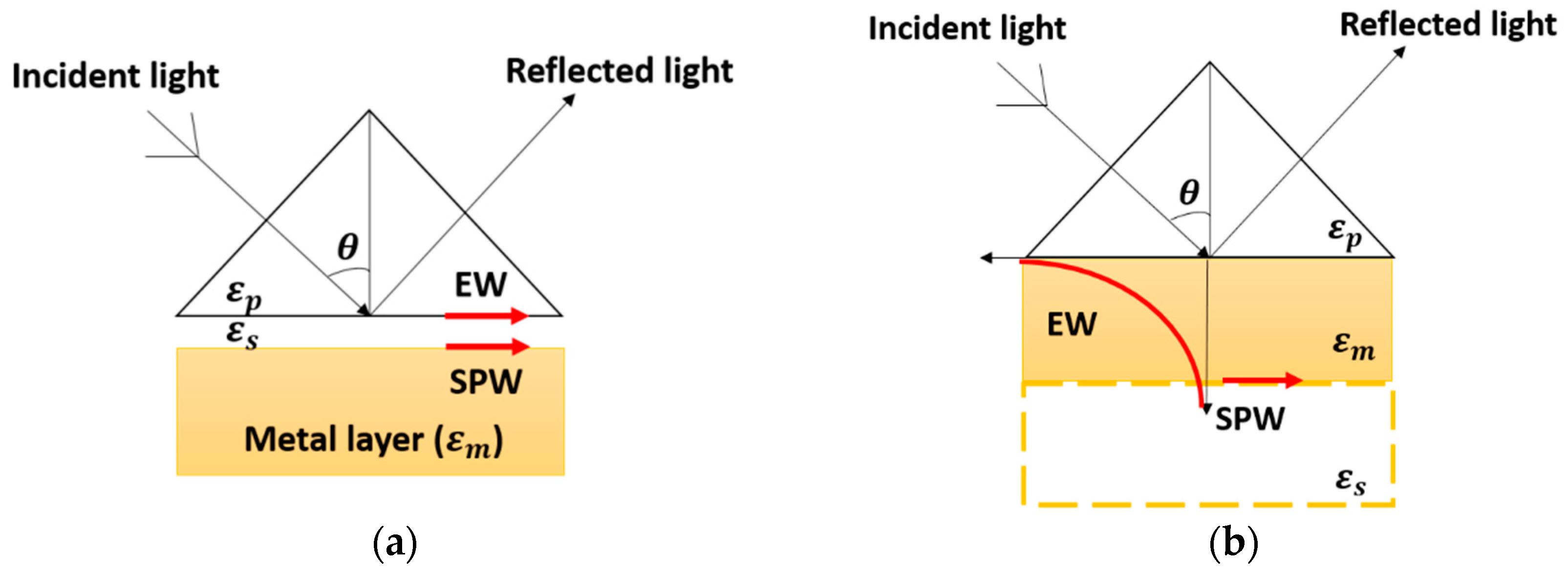
4.1. SPR in Prism Configuration
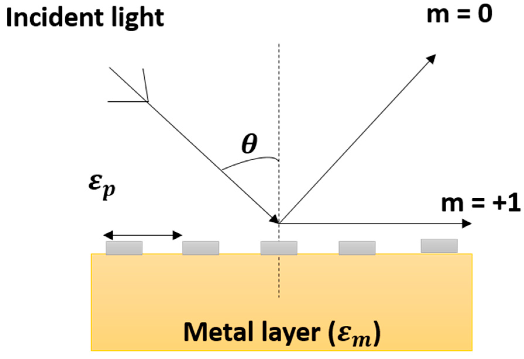
4.2. SPR in Grating Configuration
4.3. SPR in Waveguide Configuration
5. FOPS Performance Evaluation
5.1. Sensitivity
5.2. Linearity
5.3. Figure of Merit
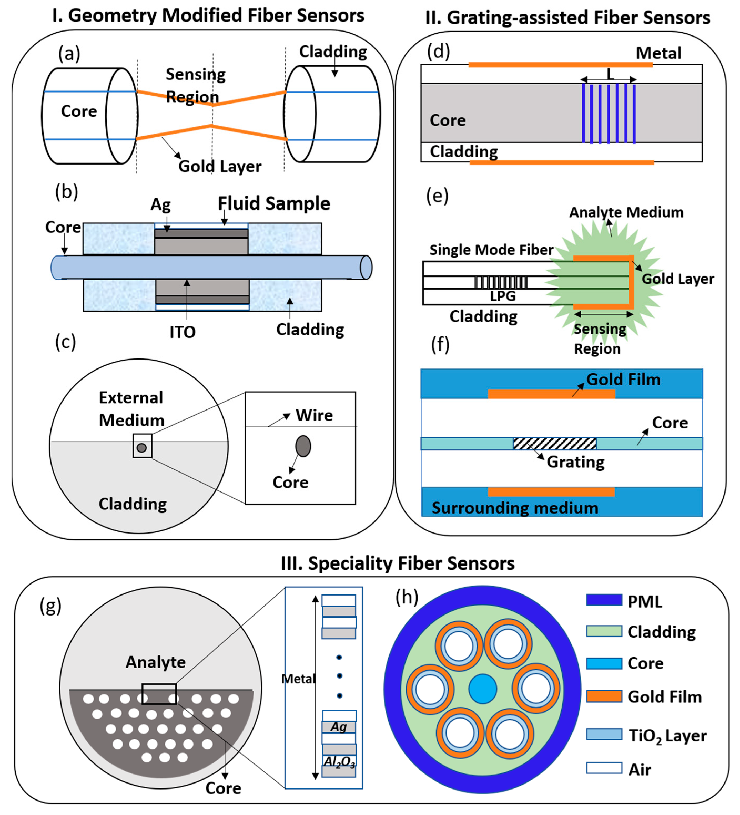
6. FOPS Geometrical Configuration and Techniques
6.1. Conventional Optical Fiber Sensors
6.2. Grating-Assisted Fiber Sensors
6.3. Specialty Fibers
6.4. Novel Techniques for Optical Fiber Sensors
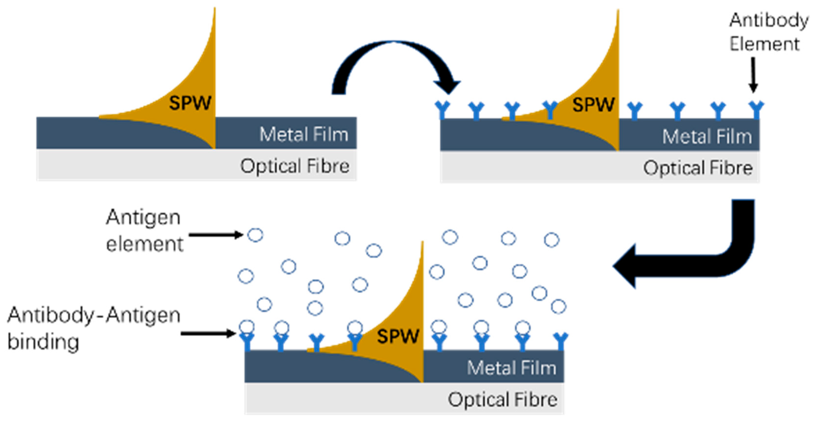
7. Concept of Surface Plasmon Resonance Biosensing
8. Applications
8.1. Medicine
8.2. Food Safety
8.3. Environmental Monitoring
9. Conclusions and Future Directions
Author Contributions
Funding
Acknowledgments
Conflicts of Interest
References
- Jorgenson, R.C.; Yee, S.S. A fiber-optic chemical sensor based on surface plasmon resonance. Sens. Actuators B Chem. 1993, 12, 213–220. [Google Scholar] [CrossRef]
- Khan, M.; Kang, S.-W.; Khan, M.R.R.; Kang, S.-W. A high sensitivity and wide dynamic range fiber-optic sensor for low-concentration VOC gas detection. Sensors 2014, 14, 23321–23336. [Google Scholar] [CrossRef] [PubMed]
- Yoo, W.J.; Jang, K.W.; Seo, J.K.; Moon, J.; Han, K.-T.; Park, J.-Y.; Park, B.G.; Lee, B.; Yoo, W.J.; Jang, K.W.; et al. Development of a 2-channel embedded infrared fiber-optic temperature sensor using silver halide optical fibers. Sensors 2011, 11, 9549–9559. [Google Scholar] [CrossRef] [PubMed]
- Poeggel, S.; Tosi, D.; Duraibabu, D.; Leen, G.; McGrath, D.; Lewis, E.; Poeggel, S.; Tosi, D.; Duraibabu, D.; Leen, G.; et al. optical fibre pressure sensors in medical applications. Sensors 2015, 15, 17115–17148. [Google Scholar] [CrossRef] [PubMed]
- Huang, Q.; Lee, J.; Arce, F.T.; Yoon, I.; Angsantikul, P.; Liu, J.; Shi, Y.; Villanueva, J.; Thamphiwatana, S.; Ma, X.; et al. Nanofibre optic force transducers with sub-piconewton resolution via near-field plasmon-dielectric interactions. Nat. Photonics 2017, 11, 352–355. [Google Scholar] [CrossRef] [PubMed]
- Huston, A.L.; Justus, B.L.; Johnson, T.L. Fiber-optic-coupled, laser heated thermoluminescence dosimeter for remote radiation sensing. Appl. Phys. Lett. 1996, 68, 3377–3379. [Google Scholar] [CrossRef]
- Yin, M.; Huang, B.; Gao, S.; Zhang, A.P.; Ye, X. Optical fiber LPG biosensor integrated microfluidic chip for ultrasensitive glucose detection. Biomed. Opt. Express 2016, 7, 2067–2077. [Google Scholar] [CrossRef] [PubMed]
- Fiber-optic Sensors for Food Safety Monitoring by Ocean Optics. Available online: https://www.bioopticsworld.com/articles/2011/12/fiber-optic-sensors-by-ocean-optics.html (accessed on 31 October 2018).
- Ricciardi, A.; Crescitelli, A.; Vaiano, P.; Quero, G.; Consales, M.; Pisco, M.; Esposito, E.; Cusano, A. Lab-on-fiber technology: A new vision for chemical and biological sensing. Analyst 2015, 140, 8068–8079. [Google Scholar] [CrossRef] [PubMed]
- Chiavaioli, F.; Baldini, F.; Tombelli, S.; Trono, C.; Giannetti, A. Biosensing with optical fiber gratings. Nanophotonics 2017, 6, 663–679. [Google Scholar] [CrossRef] [Green Version]
- Wood, R.W. XLII. On a remarkable case of uneven distribution of light in a diffraction grating spectrum. Lond. Edinb. Dublin Philos. Mag. J. Sci. 1902, 4, 396–402. [Google Scholar] [CrossRef]
- Otto, A. Excitation of nonradiative surface plasma waves in silver by the method of frustrated total reflection. Z. Physik 1968, 216, 398–410. [Google Scholar] [CrossRef]
- Raether, H. Surface plasmons on gratings. In Surface Plasmons on Smooth and Rough Surfaces and on Gratings; Raether, H., Ed.; Springer: Berlin/Heidelberg, Germany, 1988; pp. 91–116. ISBN 978-3-540-47441-8. [Google Scholar]
- Pitarke, J.M.; Silkin, V.M.; Chulkov, E.V.; Echenique, P.M. Theory of surface plasmons and surface-plasmon polaritons. Rep. Prog. Phys. 2007, 70, 1. [Google Scholar] [CrossRef]
- Gupta, B.D.; Srivastava, S.K.; Verma, R. Fiber Optic Sensors Based on Plasmonics; World Scientific: Singapore, 2014; ISBN 978-981-4619-54-7. [Google Scholar]
- Venditti, I. Gold nanoparticles in photonic crystals applications: A review. Materials 2017, 10, 97. [Google Scholar] [CrossRef] [PubMed]
- Kretschmann, E.; Raether, H. Notizen: Radiative decay of non radiative surface plasmons excited by light. Zeitschrift für Naturforschung A 2014, 23, 2135–2136. [Google Scholar] [CrossRef]
- Leung, A.; Shankar, P.M.; Mutharasan, R. Real-time monitoring of bovine serum albumin at femtogram/mL levels on antibody-immobilized tapered fibers. Sens. Actuators B Chem. 2007, 123, 888–895. [Google Scholar] [CrossRef]
- Wen-xu, L.; Jian, C. Continuous monitoring of adriamycin in vivo using fiber optic-based fluorescence chemical sensor. Anal. Chem. 2003, 75, 1458–1462. [Google Scholar] [CrossRef] [PubMed]
- Nath, N.; Jain, S.R.; Anand, S. Evanescent wave fibre optic sensor for detection of L. Donovani specific antibodies in sera of kala azar patients. Biosens. Bioelectron 1997, 12, 491–498. [Google Scholar] [CrossRef]
- Ouyang, Q.; Zeng, S.; Jiang, L.; Hong, L.; Xu, G.; Dinh, X.-Q.; Qian, J.; He, S.; Qu, J.; Coquet, P.; et al. Sensitivity enhancement of transition metal dichalcogenides/silicon nanostructure-based surface plasmon resonance biosensor. Sci. Rep. 2016, 6, 28190. [Google Scholar] [CrossRef] [PubMed]
- Mishra, A.K.; Mishra, S.K.; Gupta, B.D. SPR based fiber optic sensor for refractive index sensing with enhanced detection accuracy and figure of merit in visible region. Opt. Commun. 2015, 344, 86–91. [Google Scholar] [CrossRef]
- Sharma, A.K.; Jha, R.; Gupta, B.D. Fiber-optic sensors based on surface plasmon resonance: A comprehensive review. IEEE Sens. J. 2007, 7, 1118–1129. [Google Scholar] [CrossRef]
- Cennamo, N.; Massarotti, D.; Galatus, R.; Conte, L.; Zeni, L.; Cennamo, N.; Massarotti, D.; Galatus, R.; Conte, L.; Zeni, L. Performance comparison of two sensors based on surface plasmon resonance in a plastic optical fiber. Sensors 2013, 13, 721–735. [Google Scholar] [CrossRef] [PubMed]
- Hassani, A.; Skorobogatiy, M. Design criteria for microstructured-optical-fiber-based surface-plasmon-resonance sensors. J. Opt. Soc. Am. B. 2007, 24, 1423–1429. [Google Scholar] [CrossRef]
- Hlubina, P.; Kadulova, M.; Ciprian, D.; Sobota, J. Reflection-based fibre-optic refractive index sensor using surface plasmon resonance. J. Eur. Opt. Soc. Rapid Publ. 2014, 9, 1–5. [Google Scholar] [CrossRef]
- Jian, A.; Deng, L.; Sang, S.; Duan, Q.; Zhang, X.; Zhang, W. Surface plasmon resonance sensor based on an angled optical fiber. IEEE Sens. J. 2014, 14, 3229–3235. [Google Scholar] [CrossRef]
- Jian, A.Q.; Zhang, X.M. Resonant optical tunneling effect: recent progress in modeling and applications. IEEE J. Sel. Top. Quantum Electron. 2013, 19, 9000310. [Google Scholar] [CrossRef]
- Kim, Y.-C.; Banerji, S.; Masson, J.-F.; Peng, W.; Booksh, K.S. Fiber-optic surface plasmon resonance for vapor phase analyses. Analyst 2005, 130, 838–843. [Google Scholar] [CrossRef] [PubMed]
- Kim, Y.-C.; Peng, W.; Banerji, S.; Booksh, K.S. Tapered fiber optic surface plasmon resonance sensor for analyses of vapor and liquid phases. Opt. Lett. 2005, 30, 2218–2220. [Google Scholar] [CrossRef] [PubMed]
- Suzuki, H.; Sugimoto, M.; Matsui, Y.; Kondoh, J. Effects of gold film thickness on spectrum profile and sensitivity of a multimode-optical-fiber SPR sensor. Sens. Actuators B Chem. 2008, 132, 26–33. [Google Scholar] [CrossRef]
- Roh, S.; Chung, T.; Lee, B.; Roh, S.; Chung, T.; Lee, B. Overview of the characteristics of micro- and nano-structured surface plasmon resonance sensors. Sensors 2011, 11, 1565–1588. [Google Scholar] [CrossRef] [PubMed]
- Fu, H.; Zhang, S.; Chen, H.; Weng, J. Graphene enhances the sensitivity of fiber-optic surface plasmon resonance biosensor. IEEE Sens. J. 2015, 15, 5478–5482. [Google Scholar] [CrossRef]
- Mishra, A.K.; Mishra, S.K.; Verma, R.K. Graphene and beyond graphene MoS2: A new window in surface-plasmon-resonance-based fiber optic sensing. J. Phys. Chem. C 2016, 120, 2893–2900. [Google Scholar] [CrossRef]
- Shushama, K.N.; Rana, M.M.; Inum, R.; Hossain, M.B. Graphene coated fiber optic surface plasmon resonance biosensor for the DNA hybridization detection: Simulation analysis. Opt. Commun. 2017, 383, 186–190. [Google Scholar] [CrossRef]
- Rifat, A.A.; Mahdiraji, G.A.; Ahmed, R.; Chow, D.M.; Sua, Y.M.; Shee, Y.G.; Adikan, F.R.M. Copper-graphene-based photonic crystal fiber plasmonic biosensor. IEEE Photonics J. 2016, 8, 1–8. [Google Scholar] [CrossRef]
- Ritchie, R.H. Plasma losses by fast electrons in thin films. Phys. Rev. 1957, 106, 874–881. [Google Scholar] [CrossRef]
- Liang, G.; Luo, Z.; Liu, K.; Wang, Y.; Dai, J.; Duan, Y. Fiber optic surface plasmon resonance—Based biosensor technique: Fabrication, advancement, and application. Crit. Rev. Anal. Chem. 2016, 46, 213–223. [Google Scholar] [CrossRef] [PubMed]
- Petryayeva, E.; Krull, U.J. Localized surface plasmon resonance: Nanostructures, bioassays and biosensing—A review. Analytica Chimica Acta 2011, 706, 8–24. [Google Scholar] [CrossRef] [PubMed]
- Gupta, B.D.; Kant, R. Recent advances in surface plasmon resonance based fiber optic chemical and biosensors utilizing bulk and nanostructures. Opt. Laser Technol. 2018, 101, 144–161. [Google Scholar] [CrossRef]
- Caucheteur, C.; Guo, T.; Albert, J. Review of plasmonic fiber optic biochemical sensors: Improving the limit of detection. Anal. Bioanal. Chem. 2015, 407, 3883–3897. [Google Scholar] [CrossRef] [PubMed]
- Zhou, C. Localized surface plasmonic resonance study of silver nanocubes for photonic crystal fiber sensor. Opt. Lasers Eng. 2012, 50, 1592–1595. [Google Scholar] [CrossRef]
- Sciacca, B.; Monro, T.M. Dip biosensor based on localized surface plasmon resonance at the tip of an optical fiber. Langmuir 2014, 30, 946–954. [Google Scholar] [CrossRef] [PubMed]
- Kretschmann, E. Decay of non radiative surface plasmons into light on rough silver films. Comparison of experimental and theoretical results. Opt. Commun. 1972, 6, 185–187. [Google Scholar] [CrossRef]
- Wijaya, E.; Lenaerts, C.; Maricot, S.; Hastanin, J.; Habraken, S.; Vilcot, J.-P.; Boukherroub, R.; Szunerits, S. Surface plasmon resonance-based biosensors: From the development of different SPR structures to novel surface functionalization strategies. Curr. Opin. Solid State Mater. Sci. 2011, 15, 208–224. [Google Scholar] [CrossRef]
- Gedig, E.T. Handbook of surface plasmon resonance. In Surface Chemistry in SPR Technology; Royal Society of Chemistry: London, UK, 2017; pp. 171–220. ISBN 978-1-78801-139-6. [Google Scholar]
- Otupiri, R.; Akowuah, E.K.; Haxha, S. Multi-channel SPR biosensor based on PCF for multi-analyte sensing applications. Opt. Express 2015, 23, 15716–15727. [Google Scholar] [CrossRef] [PubMed]
- Akowuah, E.K.; Gorman, T.; Ademgil, H.; Haxha, S.; Robinson, G.K.; Oliver, J.V. Numerical analysis of a photonic crystal fiber for biosensing applications. IEEE J. Quantum Electron. 2012, 48, 1403–1410. [Google Scholar] [CrossRef]
- Rifat, A.A.; Mahdiraji, G.A.; Sua, Y.M.; Shee, Y.G.; Ahmed, R.; Chow, D.M.; Adikan, F.R.M. Surface plasmon resonance photonic crystal fiber biosensor: A practical sensing approach. IEEE Photonics Technol. Lett. 2015, 27, 1628–1631. [Google Scholar] [CrossRef]
- Chakma, S.; Khalek, M.A.; Paul, B.K.; Ahmed, K.; Hasan, M.R.; Bahar, A.N. Gold-coated photonic crystal fiber biosensor based on surface plasmon resonance: Design and analysis. Sens. Bio Sens. Res. 2018, 18, 7–12. [Google Scholar] [CrossRef]
- Chu, S.; Nakkeeran, K.; Abobaker, A.M.; Aphale, S.S.; Babu, P.R.; Senthilnathan, K. Design and analysis of surface-plasmon-resonance-based photonic quasi-crystal fiber biosensor for high-refractive-index liquid analytes. IEEE J. Sel. Top. Quantum Electron. 2019, 25, 1–9. [Google Scholar] [CrossRef]
- Sherry, L.J.; Chang, S.-H.; Schatz, G.C.; Van Duyne, R.P.; Wiley, B.J.; Xia, Y. Localized surface plasmon resonance spectroscopy of single silver nanocubes. Nano Lett. 2005, 5, 2034–2038. [Google Scholar] [CrossRef] [PubMed]
- Dwivedi, Y.S.; Sharma, A.K.; Gupta, B.D. Influence of design parameters on the performance of a surface plasmon sensor based fiber optic sensor. Plasmonics 2008, 3, 79–86. [Google Scholar] [CrossRef]
- Gauvreau, B.; Hassani, A.; Fehri, M.F.; Kabashin, A.; Skorobogatiy, M. Photonic bandgap fiber-based surface plasmon resonance sensors. Opt. Express 2007, 15, 11413–11426. [Google Scholar] [CrossRef] [PubMed]
- Wu, W.-T.; Jen, C.-P.; Tsao, T.-C.; Shen, W.-C.; Cheng, C.-W.; Chen, C.-H.; Tang, J.-L.; Li, W.-Y.; Chau, L.-K. U-shaped fiber optics fabricated with a femtosecond laser and integrated into a localized plasmon resonance biosensor. In Proceedings of the 2009 Symposium on Design, Test, Integration Packaging of MEMS/MOEMS, Rome, Italy, 1–3 April 2009; pp. 127–131. [Google Scholar]
- Verma, R.K.; Sharma, A.K.; Gupta, B.D. Surface plasmon resonance based tapered fiber optic sensor with different taper profiles. Opt. Commun. 2008, 281, 1486–1491. [Google Scholar] [CrossRef]
- Arregui, F.J.; Del Villar, I.; Corres, J.M.; Goicoechea, J.; Zamarreño, C.R.; Elosua, C.; Hernaez, M.; Rivero, P.J.; Socorro, A.B.; Urrutia, A.; et al. Fiber-optic lossy mode resonance sensors. Procedia. Eng. 2014, 87, 3–8. [Google Scholar] [CrossRef]
- Wang, H.; Yan, X.; Li, S.; An, G.; Zhang, X.; Wang, H.; Yan, X.; Li, S.; An, G.; Zhang, X. High sensitivity refractive index sensor based on dual-core photonic crystal fiber with hexagonal lattice. Sensors 2016, 16, 1655. [Google Scholar] [CrossRef] [PubMed]
- Chilwell, J.; Hodgkinson, I. Thin-films field-transfer matrix theory of planar multilayer waveguides and reflection from prism-loaded waveguides. Nature 1984, 1, 742–753. [Google Scholar] [CrossRef]
- Haddouche, I.; Cherbi, L.; Ferhat, M.L. Analytical modelization of a fiber optic-based surface plasmon resonance sensor. Opt. Commun. 2017, 402, 618–623. [Google Scholar] [CrossRef]
- Santos, D.F.; Guerreiro, A.; Baptista, J.M. Surface plasmon resonance sensor based on D-type fiber with a gold wire. Optik 2017, 139, 244–249. [Google Scholar] [CrossRef]
- Luan, N.; Wang, R.; Lv, W.; Lu, Y.; Yao, J.; Luan, N.; Wang, R.; Lv, W.; Lu, Y.; Yao, J. Surface plasmon resonance temperature sensor based on photonic crystal fibers randomly filled with silver nanowires. Sensors 2014, 14, 16035–16045. [Google Scholar] [CrossRef] [PubMed]
- Villar, I.D.; Zubiate, P.; Zamarreño, C.R.; Arregui, F.J.; Matias, I.R. Optimization in nanocoated D-shaped optical fiber sensors. Opt. Express 2017, 25, 10743–10756. [Google Scholar] [CrossRef] [PubMed]
- Qazi, H.H.; Mohammad, A.B.; Ahmad, H.; Zulkifli, M.Z.; Harun, S.W. Single-mode D-shaped optical fiber sensor for the refractive index monitoring of liquid. J. Mod. Opt. 2016, 63, 750–755. [Google Scholar] [CrossRef]
- Chen, C.-H.; Tsao, T.-C.; Tang, J.-L.; Wu, W.-T.; Chen, C.-H.; Tsao, T.-C.; Tang, J.-L.; Wu, W.-T. A Multi-D-shaped optical fiber for refractive index sensing. Sensors 2010, 10, 4794–4804. [Google Scholar] [CrossRef] [PubMed]
- Nemova, G.; Kashyap, R. Fiber-bragg-grating-assisted surface plasmon-polariton sensor. Opt. Lett. 2006, 31, 2118–2120. [Google Scholar] [CrossRef] [PubMed]
- Schuster, T.; Herschel, R.; Neumann, N.; Schäffer, C.G. Miniaturized long-period fiber grating assisted surface plasmon resonance sensor. J. Lightwave Technol. 2012, 30, 1003–1008. [Google Scholar] [CrossRef]
- Caucheteur, C.; Guo, T.; Liu, F.; Guan, B.-O.; Albert, J. Ultrasensitive plasmonic sensing in air using optical fibre spectral combs. Nat. Commun. 2016, 7, 13371. [Google Scholar] [CrossRef] [PubMed] [Green Version]
- Piliarik, M.; Homola, J.; Maníková, Z.; Čtyroký, J. Surface plasmon resonance sensor based on a single-mode polarization-maintaining optical fiber. Sens. Actuators B Chem. 2003, 90, 236–242. [Google Scholar] [CrossRef]
- Santos, D.F.; Guerreiro, A.; Baptista, J.M. SPR optimization using metamaterials in a D-type PCF refractive index sensor. Opt. Fiber Technol. 2017, 33, 83–88. [Google Scholar] [CrossRef]
- Luan, N.; Wang, R.; Lv, W.; Yao, J. Surface plasmon resonance sensor based on D-shaped microstructured optical fiber with hollow core. Opt. Express 2015, 23, 8576–8582. [Google Scholar] [CrossRef] [PubMed]
- Liu, Z.; Tam, H.-Y.; Htein, L.; Tse, M.-L.V.; Lu, C. Microstructured optical fiber sensors. J. Lightwave Technol. 2017, 35, 3425–3439. [Google Scholar] [CrossRef]
- Rindorf, L.; Jensen, J.B.; Dufva, M.; Pedersen, L.H.; Høiby, P.E.; Bang, O. Photonic crystal fiber long-period gratings for biochemical sensing. Opt. Express 2006, 14, 8224–8231. [Google Scholar] [CrossRef] [PubMed]
- Moore, J.P.; Rogge, M.D. Shape sensing using multi-core fiber optic cable and parametric curve solutions. Opt. Express 2012, 20, 2967–2973. [Google Scholar] [CrossRef] [PubMed]
- Knight, J.C.; Birks, T.A.; Mangan, B.J.; Russel, P.S.J.; Vienne, G.G.; Sandro, J.-P.D. Multicore photonic crystal fibres. In Proceedings of the 12th International Conference on Optical Fiber Sensors, Williamsburg, VA, USA, 28–31 October 1997; Optical Society of America: Washington, WA, USA, 1997; p. PDP5. [Google Scholar]
- Hassani, A.; Skorobogatiy, M. Design of the microstructured optical fiber-based surface plasmon resonance sensors with enhanced microfluidics. Opt. Express 2006, 14, 11616–11621. [Google Scholar] [CrossRef] [PubMed]
- Lu, Y.; Hao, C.-J.; Wu, B.-Q.; Huang, X.-H.; Wen, W.-Q.; Fu, X.-Y.; Yao, J.-Q.; Lu, Y.; Hao, C.-J.; Wu, B.-Q.; et al. Grapefruit fiber filled with silver nanowires surface plasmon resonance sensor in aqueous environments. Sensors 2012, 12, 12016–12025. [Google Scholar] [CrossRef] [PubMed]
- Wong, W.C.; Chan, C.C.; Boo, J.L.; Teo, Z.Y.; Tou, Z.Q.; Yang, H.B.; Li, C.M.; Leong, K.C. Photonic crystal fiber surface plasmon resonance biosensor based on protein G immobilization. IEEE J. Sel. Top. Quantum Electron. 2013, 19, 4602107. [Google Scholar] [CrossRef]
- Gao, D.; Guan, C.; Wen, Y.; Zhong, X.; Yuan, L. Multi-hole fiber based surface plasmon resonance sensor operated at near-infrared wavelengths. Opt. Commun. 2014, 313, 94–98. [Google Scholar] [CrossRef]
- Cennamo, N.; D’Agostino, G.; Donà, A.; Dacarro, G.; Pallavicini, P.; Pesavento, M.; Zeni, L.; Cennamo, N.; D’Agostino, G.; Donà, A.; et al. Localized surface plasmon resonance with five-branched gold nanostars in a plastic optical fiber for bio-chemical sensor implementation. Sensors 2013, 13, 14676–14686. [Google Scholar] [CrossRef] [PubMed]
- Teng, C.; Yu, F.; Ding, Y.; Zheng, J. Refractive index sensor based on multi-mode plastic optical fiber with long period grating. In Proceedings of the Optical Sensors, New Orleans, LA, USA, 24–27 July 2017; International Society for Optics and Photonics: Bellingham, WA, USA, 2017; Volume 10231, p. 102311. [Google Scholar]
- Nenninger, G.G.; Tobiška, P.; Homola, J.; Yee, S.S. Long-range surface plasmons for high-resolution surface plasmon resonance sensors. Sens. Actuators B Chem. 2001, 74, 145–151. [Google Scholar] [CrossRef]
- Chien, F.-C.; Chen, S.-J. A sensitivity comparison of optical biosensors based on four different surface plasmon resonance modes. Biosens. Bioelectron. 2004, 20, 633–642. [Google Scholar] [CrossRef] [PubMed]
- Ekgasit, S.; Thammacharoen, C.; Knoll, W. Surface plasmon resonance spectroscopy based on evanescent field treatment. Anal. Chem. 2004, 76, 561–568. [Google Scholar] [CrossRef] [PubMed]
- Wark, A.W.; Lee, H.J.; Corn, R.M. Long-range surface plasmon resonance imaging for bioaffinity sensors. Anal. Chem. 2005, 77, 3904–3907. [Google Scholar] [CrossRef] [PubMed]
- Berini, P. Long-range surface plasmon polaritons. Adv. Opt. Photon. 2009, 1, 484–588. [Google Scholar] [CrossRef]
- Yashunsky, V.; Lirtsman, V.; Golosovsky, M.; Davidov, D.; Aroeti, B. Real-time monitoring of epithelial cell-cell and cell-substrate interactions by infrared surface plasmon spectroscopy. Biophys. J. 2010, 99, 4028–4036. [Google Scholar] [CrossRef] [PubMed]
- Abbas, A.; Linman, M.J.; Cheng, Q. New trends in instrumental design for surface plasmon resonance-based biosensors. Biosens. Bioelectron. 2011, 26, 1815–1824. [Google Scholar] [CrossRef] [PubMed] [Green Version]
- Watad, I.; Abdulhalim, I. Comparative study between polarimetric and intensity-based surface plasmon resonance sensors in the spectral mode. Appl. Opt. 2017, 56, 7549–7558. [Google Scholar] [CrossRef] [PubMed]
- Parveen, S.; Pathak, A.; Gupta, B.D. Fiber optic SPR nanosensor based on synergistic effects of CNT/Cu-nanoparticles composite for ultratrace sensing of nitrate. Sens. Actuators B Chem. 2017, 246, 910–919. [Google Scholar] [CrossRef]
- Abdulhalim, I. Coupling configurations between extended surface electromagnetic waves and localized surface plasmons for ultrahigh field enhancement. Nanophotonics 2018, 7, 1891–1916. [Google Scholar] [CrossRef]
- Semwal, V.; Gupta, B.D. LSPR- and SPR-based fiber-optic cholesterol sensor using immobilization of cholesterol oxidase over silver nanoparticles coated graphene oxide nanosheets. IEEE Sens. J. 2018, 18, 1039–1046. [Google Scholar] [CrossRef]
- Homola, J. Present and future of surface plasmon resonance biosensors. Anal. Bioanal. Chem. 2003, 377, 528–539. [Google Scholar] [CrossRef] [PubMed]
- Consales, M.; Ricciardi, A.; Crescitelli, A.; Esposito, E.; Cutolo, A.; Cusano, A. Lab-on-fiber technology: Toward multifunctional optical nanoprobes. ACS Nano 2012, 6, 3163–3170. [Google Scholar] [CrossRef] [PubMed]
- Gupta, B.D.; Verma, R.K. Surface plasmon resonance-based fiber optic sensors: Principle, probe designs, and some applications. J. Sens. 2009, 2009, 12. [Google Scholar] [CrossRef]
- Wolfbeis, O.S.; Weidgans, B.M. Fiber optic chemical sensors and biosensors: A view back. In Proceedings of the Optical Chemical Sensors; Baldini, F., Chester, A.N., Homola, J., Martellucci, S., Eds.; Springer: Dordrecht, The Netherlands, 2006; pp. 17–44. [Google Scholar]
- Yin, S.; Ruffin, P. Fiber optic sensors. In Wiley Encyclopedia of Biomedical Engineering; American Cancer Society: Atlanta, GA, USA, 2006; ISBN 978-0-471-74036-0. [Google Scholar]
- Urrutia, A.; Goicoechea, J.; Arregui, F.J. Optical fiber sensors based on nanoparticle-embedded coatings. J. Sens. 2015. [Google Scholar] [CrossRef]
- Sharma, P.; Sharan, P.; Deshmukh, P. A photonic crystal sensor for analysis and detection of cancer cells. In Proceedings of the 2015 International Conference on Pervasive Computing (ICPC), Pune, India, 8–10 January 2015; pp. 1–5. [Google Scholar]
- American Cancer Society. Cancer Facts & Figures 2016. Available online: https://www.cancer.org/content/dam/cancer-org/research/cancer-facts-and-statistics/annual-cancer-facts-and-figures/2016/cancer-facts-and-figures-2016.pdf (accessed on 31 October 2018).
- Chopra, H.; Kaler, R.S.; Painam, B. Photonic crystal waveguide-based biosensor for detection of diseases. J. Nanophotonics 2016, 10, 036011. [Google Scholar] [CrossRef]
- Zhang, J.; Hodge, W.; Hutnick, C.; Wang, X. Noninvasive diagnostic devices for diabetes through measuring tear glucose. J. Diabetes Sci Technol. 2011, 5, 166–172. [Google Scholar] [CrossRef] [PubMed]
- Narsaiah, K.; Jha, S.N.; Bhardwaj, R.; Sharma, R.; Kumar, R. Optical biosensors for food quality and safety assurance—A review. J. Food Sci Technol. 2012, 49, 383–406. [Google Scholar] [CrossRef] [PubMed]
- Cooper, M.A. Optical biosensors in drug discovery. Nat. Rev. Drug Discov. 2002, 1, 515–528. [Google Scholar] [CrossRef] [PubMed]
- Wan, M.; Luo, P.; Jin, J.; Xing, J.; Wang, Z.; Wong, S.T.C.; Wan, M.; Luo, P.; Jin, J.; Xing, J.; et al. Fabrication of localized surface plasmon resonance fiber probes using ionic self-assembled gold nanoparticles. Sensors 2010, 10, 6477–6487. [Google Scholar] [CrossRef] [PubMed]
- Situ, C.; Mooney, M.H.; Elliott, C.T.; Buijs, J. Advances in surface plasmon resonance biosensor technology towards high-throughput, food-safety analysis. TrAC Trends Anal. Chem. 2010, 29, 1305–1315. [Google Scholar] [CrossRef]
- Narsaiah, K.; Jha, S.N. Nondestructive methods for quality evaluation of livestock products. J. Food Sci. Technol. 2012, 49, 342–348. [Google Scholar] [CrossRef] [PubMed]
- Srivastava, S.K.; Verma, R.; Gupta, B.D. Surface plasmon resonance based fiber optic glucose biosensor. In Proceedings of the Third Asia Pacific Optical Sensors Conference, International Society for Optics and Photonics, Sidney, Australia, 31 January–3 February 2012; Volume 8351, p. 83511Z. [Google Scholar]
- Luo, B.; Yan, Z.; Sun, Z.; Li, J.; Zhang, L. Novel glucose sensor based on enzyme-immobilized 81° tilted fiber grating. Opt. Express 2014, 22, 30571–30578. [Google Scholar] [CrossRef] [PubMed]
- Piliarik, M.; Bocková, M.; Homola, J. Surface plasmon resonance biosensor for parallelized detection of protein biomarkers in diluted blood plasma. Biosens. Bioelectron. 2010, 26, 1656–1661. [Google Scholar] [CrossRef] [PubMed]
- Sharma, P.; Asad, S.; Ali, A. Bioluminescent bioreporter for assessment of arsenic contamination in water samples of India. J. Biosci. 2013, 38, 251–258. [Google Scholar] [CrossRef] [PubMed]
- Gui, Q.; Lawson, T.; Shan, S.; Yan, L.; Liu, Y.; Gui, Q.; Lawson, T.; Shan, S.; Yan, L.; Liu, Y. The application of whole cell-based biosensors for use in environmental analysis and in medical diagnostics. Sensors 2017, 17, 1623. [Google Scholar] [CrossRef] [PubMed]
- Cardona-Maya, Y.; Villar, I.D.; Socorro, A.B.; Corres, J.M.; Arregui, F.J.; Botero-Cadavid, J.F. Etched and nanocoated sms fiber sensor for detection of salinity concentration. Proceedings 2017, 1, 333. [Google Scholar] [CrossRef]
- Al-Qazwini, Y.; Noor, A.S.M.; Al-Qazwini, Z.; Yaacob, M.H.; Harun, S.W.; Mahdi, M.A. Refractive index sensor based on SPR in symmetrically etched plastic optical fibers. Sens. Actuators A Phys. 2016, 246, 163–169. [Google Scholar] [CrossRef]
- Tahhan, S.R.; Chen, R.Z.; Huang, S.; Hajim, K.I.; Chen, K.P. Fabrication of fiber bragg grating coating with TiO2 nanostructured metal oxide for refractive index sensor. J. Nanotechnol. 2017, 2007, 9. [Google Scholar] [CrossRef]
- Guo, T.; Liu, F.; Liang, X.; Qiu, X.; Huang, Y.; Xie, C.; Xu, P.; Mao, W.; Guan, B.-O.; Albert, J. Highly sensitive detection of urinary protein variations using tilted fiber grating sensors with plasmonic nanocoatings. Biosens. Bioelectron. 2016, 78, 221–228. [Google Scholar] [CrossRef] [PubMed] [Green Version]
- Díaz-Herrera, N.; González-Cano, A.; Viegas, D.; Santos, J.L.; Navarrete, M.-C. Refractive index sensing of aqueous media based on plasmonic resonance in tapered optical fibres operating in the 1.5 μm region. Sens. Actuators B Chem. 2010, 146, 195–198. [Google Scholar] [CrossRef]
- Goswami, N.; Chauhan, K.K.; Saha, A. Analysis of surface plasmon resonance based bimetal coated tapered fiber optic sensor with enhanced sensitivity through radially polarized light. Opt. Commun. 2016, 379, 6–12. [Google Scholar] [CrossRef]
- Zhu, S.; Pang, F.; Huang, S.; Zou, F.; Guo, Q.; Wen, J.; Wang, T.; Zhu, S.; Pang, F.; Huang, S.; et al. High sensitivity refractometer based on TiO2-coated adiabatic tapered optical fiber via ALD technology. Sensors 2016, 16, 1295. [Google Scholar] [CrossRef] [PubMed]
- Tang, J.; Zhou, J.; Guan, J.; Long, S.; Yu, J.; Guan, H.; Lu, H.; Luo, Y.; Zhang, J.; Chen, Z. Fabrication of side-polished single mode-multimode-single mode fiber and its characteristics of refractive index sensing. IEEE J. Sel. Top. Quantum Electron. 2017, 23, 238–245. [Google Scholar] [CrossRef]
- Kant, R.; Tabassum, R.; Gupta, B.D. Fiber optic SPR-based uric acid biosensor using uricase entrapped polyacrylamide gel. IEEE Photonics Technol. Lett. 2016, 28, 2050–2053. [Google Scholar] [CrossRef]
- Lin, H.-Y.; Tsao, Y.-C.; Tsai, W.-H.; Yang, Y.-W.; Yan, T.-R.; Sheu, B.-C. Development and application of side-polished fiber immunosensor based on surface plasmon resonance for the detection of Legionella pneumophila with halogens light and 850 nm-LED. Sens. Actuators A Phys. 2007, 138, 299–305. [Google Scholar] [CrossRef]
- Dong, H.; Yu, J.; Yu, J.; Guan, H.; Guan, H.; Qiu, W.; Dong, J.; Lu, H.; Lu, H.; Tang, J.; et al. Coreless side-polished fiber for multimode interference and highly sensitive refractive index sensing. In Proceedings of the Optics in the Life Sciences Congress, San Diego, CA, USA, 15–17 April 2017; paper BoW4A.5. Optical Society of America: Washington, DC, USA, 2017; p. BoW4A.5. [Google Scholar]
- Chen, J.; Shi, S.; Su, R.; Qi, W.; Huang, R.; Wang, M.; Wang, L.; He, Z.; Chen, J.; Shi, S.; et al. Optimization and application of reflective LSPR optical fiber biosensors based on silver nanoparticles. Sensors 2015, 15, 12205–12217. [Google Scholar] [CrossRef] [PubMed]
- Xie, Q.; Chen, Y.; Li, X.; Yin, Z.; Wang, L.; Geng, Y.; Hong, X. Characteristics of D-shaped photonic crystal fiber surface plasmon resonance sensors with different side-polished lengths. Appl. Opt. 2017, 56, 1550–1555. [Google Scholar] [CrossRef]
- Huang, T. Highly sensitive SPR sensor based on D-shaped photonic crystal fiber coated with indium tin oxide at near-infrared wavelength. Plasmonics 2017, 12, 583–588. [Google Scholar] [CrossRef]
- Rifat, A.A.; Ahmed, R.; Mahdiraji, G.A.; Adikan, F.R.M. Highly sensitive D-shaped photonic crystal fiber-based plasmonic biosensor in visible to near-IR. IEEE Sens. J. 2017, 17, 2776–2783. [Google Scholar] [CrossRef]
- Zhang, C.; Li, Z.; Jiang, S.Z.; Li, C.H.; Xu, S.C.; Yu, J.; Li, Z.; Wang, M.H.; Liu, A.H.; Man, B.Y. U-bent fiber optic SPR sensor based on graphene/AgNPs. Sens. Actuators B Chem. 2017, 251, 127–133. [Google Scholar] [CrossRef]
- Hasan, M.; Akter, S.; Rifat, A.; Rana, S.; Ali, S.; Hasan, M.R.; Akter, S.; Rifat, A.A.; Rana, S.; Ali, S. A highly sensitive gold-coated photonic crystal fiber biosensor based on surface plasmon resonance. Photonics 2017, 4, 18. [Google Scholar] [CrossRef]
- Wu, T.; Shao, Y.; Wang, Y.; Cao, S.; Cao, W.; Zhang, F.; Liao, C.; He, J.; Huang, Y.; Hou, M.; et al. Surface plasmon resonance biosensor based on gold-coated side-polished hexagonal structure photonic crystal fiber. Opt. Express 2017, 25, 20313–20322. [Google Scholar] [CrossRef] [PubMed]
- Tu, M.H.; Sun, T.; Grattan, K.T.V. LSPR optical fibre sensors based on hollow gold nanostructures. Sens. Actuators B Chem. 2014, 191, 37–44. [Google Scholar] [CrossRef]
- Jiang, S.; Li, Z.; Zhang, C.; Gao, S.; Li, Z.; Qiu, H.; Li, C.; Yang, C.; Mei, L.; Liu, Y. A novel U-bent plastic optical fibre local surface plasmon resonance sensor based on a graphene and silver nanoparticle hybrid structure. J. Phys. D Appl. Phys. 2017, 50, 165105. [Google Scholar] [CrossRef]
- Yang, X.C.; Lu, Y.; Liu, B.L.; Yao, J.Q. Temperature sensor based on photonic crystal fiber filled with liquid and silver nanowires. IEEE Photonics J. 2016, 8, 1–9. [Google Scholar] [CrossRef]
- Su, Y.; Wei, Y.; Zhang, Y.; Liu, C.; Nie, X.; Zhu, Z.; Liu, L. Surface-plasmon-resonance-based optical fiber curvature sensor with temperature compensation by means of dual modulation method. Sensors 2018, 18, 2608. [Google Scholar] [CrossRef] [PubMed]
- Mahdiraji, G.A.; Chow, D.M.; Sandoghchi, S.R.; Amirkhan, F.; Dermosesian, E.; Yeo, K.S.; Kakaei, Z.; Ghomeishi, M.; Poh, S.Y.; Gang, S.Y.; et al. Challenges and solutions in fabrication of silica-based photonic crystal fibers: an experimental study. Fiber Integr. Opt. 2014, 33, 85–104. [Google Scholar] [CrossRef]
- Knight, J.C.; Birks, T.A.; Russell, P.S.J.; Atkin, D.M. All-silica single-mode optical fiber with photonic crystal cladding. Opt. Lett. 1996, 21, 1547–1549. [Google Scholar] [CrossRef] [PubMed]
- Bise, R.T.; Trevor, D. Solgel-derived microstructured fibers: Fabrication and characterization. In Proceedings of the Optical Fiber Communication Conference and Exposition and The National Fiber Optic Engineers Conference, Anaheim, CA, USA, 6–11 March 2005; paper OWL6. Optical Society of America: Washington, DC, USA, 2005; p. OWL6. [Google Scholar]
- Yajima, T.; Yamamoto, J.; Ishii, F.; Hirooka, T.; Yoshida, M.; Nakazawa, M. Low-loss photonic crystal fiber fabricated by a slurry casting method. Opt. Express 2013, 21, 30500–30506. [Google Scholar] [CrossRef] [PubMed]
- Kumar, V.V.R.K.; George, A.K.; Reeves, W.H.; Knight, J.C.; Russell, P.S.J.; Omenetto, F.G.; Taylor, A.J. Extruded soft glass photonic crystal fiber for ultrabroad supercontinuum generation. Opt. Express 2002, 10, 1520–1525. [Google Scholar] [CrossRef] [PubMed]
- Tajima, K. Low loss PCF by reduction of hole surface imperfection. In Proceedings of the 33rd European Conference and Exhibition of Optical Communication, Berlin, Germany, 16–20 September 2007; Post-Deadline Papers (published 2008). pp. 1–2. [Google Scholar]
- Takeyasu, N.; Tanaka, T.; Kawata, S. Metal deposition deep into microstructure by electroless plating. Jpn. J. Appl. Phys. 2005, 44, L1134. [Google Scholar] [CrossRef]
- Sazio, P.J.A.; Amezcua-Correa, A.; Finlayson, C.E.; Hayes, J.R.; Scheidemantel, T.J.; Baril, N.F.; Jackson, B.R.; Won, D.-J.; Zhang, F.; Margine, E.R.; et al. microstructured optical fibers as high-pressure microfluidic reactors. Science 2006, 311, 1583–1586. [Google Scholar] [CrossRef] [PubMed]
- Boehm, J.; François, A.; Ebendorff-Heidepriem, H.; Monro, T.M. Chemical deposition of silver for the fabrication of surface plasmon microstructured optical fibre sensors. Plasmonics 2011, 6, 133–136. [Google Scholar] [CrossRef]
- Sandlin, S.; Kinnunen, T.; Rämö, J.; Sillanpää, M. A simple method for metal re-coating of optical fibre Bragg gratings. Surf. Coat. Technol. 2006, 201, 3061–3065. [Google Scholar] [CrossRef]
- Lu, J.; Van Stappen, T.; Spasic, D.; Delport, F.; Vermeire, S.; Gils, A.; Lammertyn, J. Fiber optic-SPR platform for fast and sensitive infliximab detection in serum of inflammatory bowel disease patients. Biosens. Bioelectron. 2016, 79, 173–179. [Google Scholar] [CrossRef] [PubMed] [Green Version]
- Liu, Q.; Yuan, H.; Liu, Y.; Wang, J.; Jing, Z.; Peng, W. Real-time biodetection using a smartphone-based dual-color surface plasmon resonance sensor. J. Biomed. Opt. 2018, 23, 047003. [Google Scholar] [CrossRef] [PubMed]


| Sensor Configuration and Its Application | Operating Wavelength (nm) | Functional Materials | Performance with Sample Range | Ref. |
|---|---|---|---|---|
| Etched optical fiber for detection of salinity concentration | 1400–1600 | SMF + MMF + SMF coated with ITO | 7000 nm/RIU for RI ranges from 1.333 to 1.338. | [113] |
| Symmetrically-etched POF sensor for RI sensing application | 350–1100 | Etched POF coated with Au | 1600 nm/RIU for RI ranges from 1.3353 to 1.3453. | [114] |
| Etched-optical fiber Bragg grating for sensing deionized water and saline | 400–1600 | Etched D-shaped fiber Bragg grating coated with TiO2 | 1.257 nm/RIU for air-deionized water and 0.857 nm/RIU for air-saline for the corresponding RI 1 and 1.318. | [115] |
| Tilted fiber Bragg grating sensor for detecting urinary protein variations | 1440–1540 | Tilted fiber Bragg grating coated with Ag | 8000 dB/RIU for RI ranges from 1.3400 to 1.3408 | [116] |
| Tapered fiber SPR-based sensing systems for remote measurement of chemical and biological parameters | 450–1700 | Cr + Au + TiO2 coated on fiber | 5000 nm/RIU at 1500 nm for RI ranges from 1.332 to 1.338. | [117] |
| Tapered multimode fiber sensor for RI detection sensors | 400–1200 | Ag + Au coated on fiber | 10 times as compared to the symmetric fiber sensing probe for RI ranges from 1.333–1.353 | [118] |
| Adiabatic tapered optical fiber sensor for biochemical sensing | 400–2000 | Tapered optical fiber + TiO2 | 7096 nm/RIU for RI ranges from 1.3373 to 1.3500 | [119] |
| Side polished single mode-multimode-single mode fiber for sensing characteristics | 1450–1610 | SMF + MMF + SMF 30 mm, 35 mm, 40 mm, and 45 mm | The highest sensitivity of 65 nm/RIU in RI range from 1.33 to 1.39, and of 1190 nm/RIU in RI range from 1.43 to 1.45. | [120] |
| Side-polished plastic optical fiber for biochemical application | 400–1100 | Ag + silicon + Polyacrylamide Gel with uricase enzyme | 10.50 nm/mM in the range 0–0.9 mM | [121] |
| Side-polished single-mode fiber for the detection of Legionella pneumophila | 400–1800 | Au + SAM + antigen LP coated on fiber | Legionella pneumophila LOD 101 CFU/ml | [122] |
| Coreless side-polished fiber for multimode interference and refractive index sensors | 1100–1650 | lead in SMF, transitional section | 15,666 nm/RIU in SRI range from 1.438 to 1.444 | [123] |
| 1, coreless flat section, transitional section | ||||
| 2, and lead-out SMF | ||||
| Ag NP-based LSPR optical fiber biosensor for detecting the anti-human IgG | 200–800 | Human IgG + immobilized on the sensor probe | 387 nm/RIU for RI ranges from 1.33 to 1.40. | [124] |
| D-shaped fiber SPR-based plasmonic sensor | 500–1200 | Au coated on fiber | 7381 nm/RIU for RI ranges from 1.40 to 1.42. | [125] |
| D-shaped fiber SPR-based plasmonic sensor | 1000–1100 | ITO coated on fiber | 6000 nm RIU for RI ranges from 1.30 to 1.31 | [126] |
| D-shaped fiber SPR-based biosensor | 500–1720 | Au + TiO2 coated on fiber | 46,000 nm/RIU at 1130 nm for RI ranges from 1.34 to 1.35. | [127] |
| U-bent fiber optic SPR sensor for medicine, biotechnology and food safety | 300–800 | Ag NPs coated on U-bent optical fiber | 1198 nm/RIU for RI ranges from 1.3657 to 1.3557. | [128] |
| PCF biosensor for biological analyte detection | 500–740 | Au coated outside of the PCF structure | 2200 nm/RIU for RI ranges from 1.33 to 1.36. | [129] |
| Side-polished D-shaped PCF for bio-chemical detection | 500–900 | Ag-coated side-polished hexagonal structure PCF | 21,700 nm/RIU for RI ranges from 1.33 to 1.34 | [130] |
| LSPR-based optical fiber sensor for RI measurements | 200–1100 | Ag NPs are coated on optical fiber | 1933 nm/RIU for 1.333 to 1.404 | [131] |
| U-bent plastic optical fiber sensor for biosensing | 300–800 | Ag thin film was deposited on U-bent optical fiber | 700.3 nm/RIU for ranges from 1.330 to 1.3657 | [132] |
| Type of Metal Coating | Advantage | Disadvantage | FOPS Geometric Structure |
|---|---|---|---|
| Selective metal coating [76] | Analyte is filled in the chosen air hole cell | Metal coating is challenging on the circular air holes |  |
| External metal coating [50] | Analyte is filled in the external surface of the fiber | Different air hole sizes are required. |  |
| Internal nanowire filling [133] | Analyte is filled in the nanowire | Selective filling of air hole in nano size is challenging |  |
| Side-polished [125] | A flow of analyte is allowed at the outer surface of the fiber | A precise etching and polishing exertion are needed |  |
| Micro-fluidic slots [76] | Various analytes can be analyzed at the same time | Making the metal slots is challenging |  |
© 2019 by the authors. Licensee MDPI, Basel, Switzerland. This article is an open access article distributed under the terms and conditions of the Creative Commons Attribution (CC BY) license (http://creativecommons.org/licenses/by/4.0/).
Share and Cite
Gandhi, M.S.A.; Chu, S.; Senthilnathan, K.; Babu, P.R.; Nakkeeran, K.; Li, Q. Recent Advances in Plasmonic Sensor-Based Fiber Optic Probes for Biological Applications. Appl. Sci. 2019, 9, 949. https://0-doi-org.brum.beds.ac.uk/10.3390/app9050949
Gandhi MSA, Chu S, Senthilnathan K, Babu PR, Nakkeeran K, Li Q. Recent Advances in Plasmonic Sensor-Based Fiber Optic Probes for Biological Applications. Applied Sciences. 2019; 9(5):949. https://0-doi-org.brum.beds.ac.uk/10.3390/app9050949
Chicago/Turabian StyleGandhi, M. S. Aruna, Suoda Chu, K. Senthilnathan, P. Ramesh Babu, K. Nakkeeran, and Qian Li. 2019. "Recent Advances in Plasmonic Sensor-Based Fiber Optic Probes for Biological Applications" Applied Sciences 9, no. 5: 949. https://0-doi-org.brum.beds.ac.uk/10.3390/app9050949