Friction and Dynamics of Verge and Foliot: How the Invention of the Pendulum Made Clocks Much More Accurate


Mechanical Engineering, University of Wisconsin-Milwaukee, 3200 N Cramer St, Milwaukee, WI 53211, USA
*
Author to whom correspondence should be addressed.
Appl. Mech. 2020, 1(2), 111-122; https://0-doi-org.brum.beds.ac.uk/10.3390/applmech1020008
Submission received: 1 April 2020
/
Revised: 25 April 2020
/
Accepted: 27 April 2020
/
Published: 29 April 2020
Abstract
:The tower clocks designed and built in Europe starting from the end of the 13th century employed the “verge and foliot escapement” mechanism. This mechanism provided a relatively low accuracy of time measurement. The introduction of the pendulum into the clock mechanism by Christiaan Huygens in 1658–1673 improved the accuracy by about 30 times. The improvement is attributed to the isochronicity of small linear vibrations of a mathematical pendulum. We develop a mathematical model of both mechanisms. Using scaling arguments, we show that the introduction of the pendulum resulted in accuracy improvement by approximately π/μ ≈ 30 times, where μ ≈ 0.1 is the coefficient of friction. Several historic clocks are discussed, as well as the implications of both mechanisms to the history of science and technology.
“And as wheels in the movements of a clockturn in such a way that, to an observer,the innermost seems standing still, the outermost to fly”.(Dante, Commedia, “Paradiso” 24:13–15; before 1321 CE)
1. Introduction
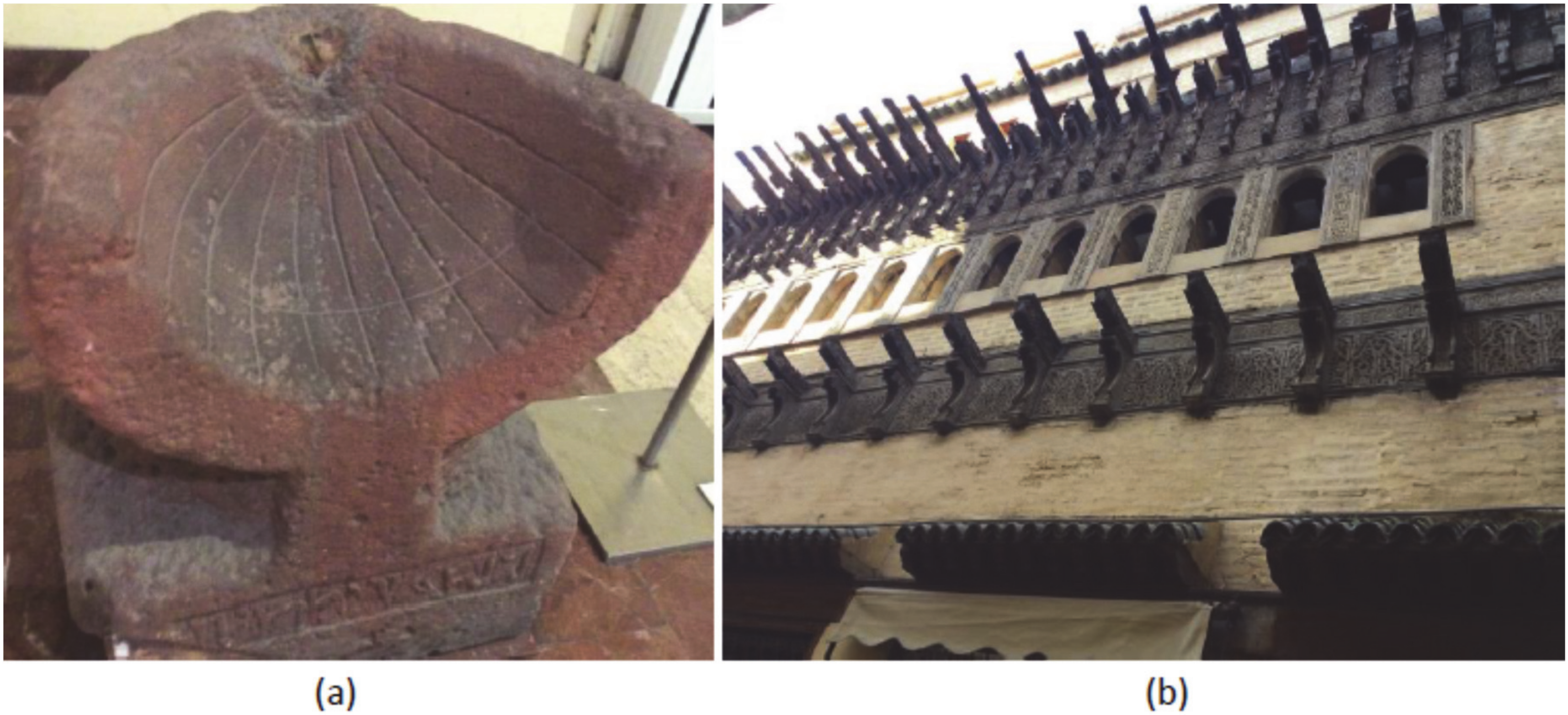
Accurate time measurement was among the most important technological problems throughout the history of humankind. Various devices were designed for this purpose including the sun clock (sundial) [1], water clock (clepsydra), fire clock, and sand clock (sand glasses) (Figure 1). All these devices use either a uniform flow of material, such as water or sand, or a process with more or less a constant rate, such as the sun’s motion and a candle burning [2,3].
A different principle is employed by mechanical clocks, which emerged in Europe by the end of the 13th century [2,3,4,5]. To achieve accurate time measurement, mechanical clocks rely on a periodic motion (oscillation) of a mechanical shaft called the verge. However, prior to the invention of the pendulum, achieving a periodic motion was a non-trivial task. The mechanism of an early mechanical clock is referred to as the “verge-and-foliot escapement,” and it consisted of a verge and a crossbar, called a foliot, with weights attached to each end [6]. The weights could be moved to different positions on the crossbar, tuning its moment of inertia, so that the period of oscillations was dependent on the distance of the weights from the center.
It is not known who invented the verge-and-foliot escapement mechanism. Some historians suggest that a description of the mechanical clock is found in the 1271 CE treatise by an English astronomer Robertus Anglicus (Robert the Englishman). In fact, the author stated that a mechanical clock would be needed, but had not been successfully created so far. The first escapement mechanism is often attributed to the French architect Wilars de Honecourt, whose notes, made between 1240 and 1251 CE, contain drawings of various mechanisms including what is possibly an escapement. However, the first clear drawing of an escapement was found only in a 1364 CE manuscript of a treatise by Jacopo di Dondi dell ‘Orologio (1290–1359) and his son Giovanni de’Dondi (1318–1389) [2,3,4,5].
The first known example of a verge-and-foliot tower clock was built in the town of Dunstable in England in 1283 CE. Other famous early mechanical tower clocks include St. Paul’s Cathedral in London (1286), Westminster (1288), Canterbury (1292), Strasbourg (1352/1354), Paris (1362), Padua (1364), and Salisbury (1386) [2].
During the 14th century, tower clocks became a familiar element of urban life in Europe. The “cerchi in tempra d’orïuoli” (“wheels in the movements of a clock”) and “orologio che ne chiami ne l’ora” (“a clock that calls us at the hour”) are mentioned by Dante in his Divina Commedia (“Paradiso” X, 139 and XXIV, 13, written between 1315 and 1321 CE). The English poet Geoffrey Chaucer said about a rooster, a bird that wakes up early in the morning: “Well sikerer was his crowing in his lodge/Than is a clock of any abbey orloge” (“Canterbury Tales” written between 1387 and 1400 CE). Here “sikerer” means “more accurate,” “clock” means a “bell,” and “orloge” means a “clock”).
Interestingly, the verge and foliot escapement mechanism was invented almost simultaneously with the sandglass. The earliest medieval evidence of sandglasses appears in the 1338 fresco “Allegory of Good Government” by Ambrogio Lorenzetti, where it serves as an allegory of temperance. Although sandglasses could hardly be used for marine navigation due to their limited accuracy, their invention and spreading was stimulated by their use on ships for regulating sailors activity because water clocks could not be used in the wet, rough, constantly moving environment of a ship [7]. Balmer noted that “it is possible that the societal concept of time was evolving from a nebulous continuum to a quantifiable organizable duration. there are two other well-documented uses of [sand clocks] during the late Middle Ages: by scholars, apparently for regulating their routines of study, and by the clergy for regulating their sermons and meditations” [7].
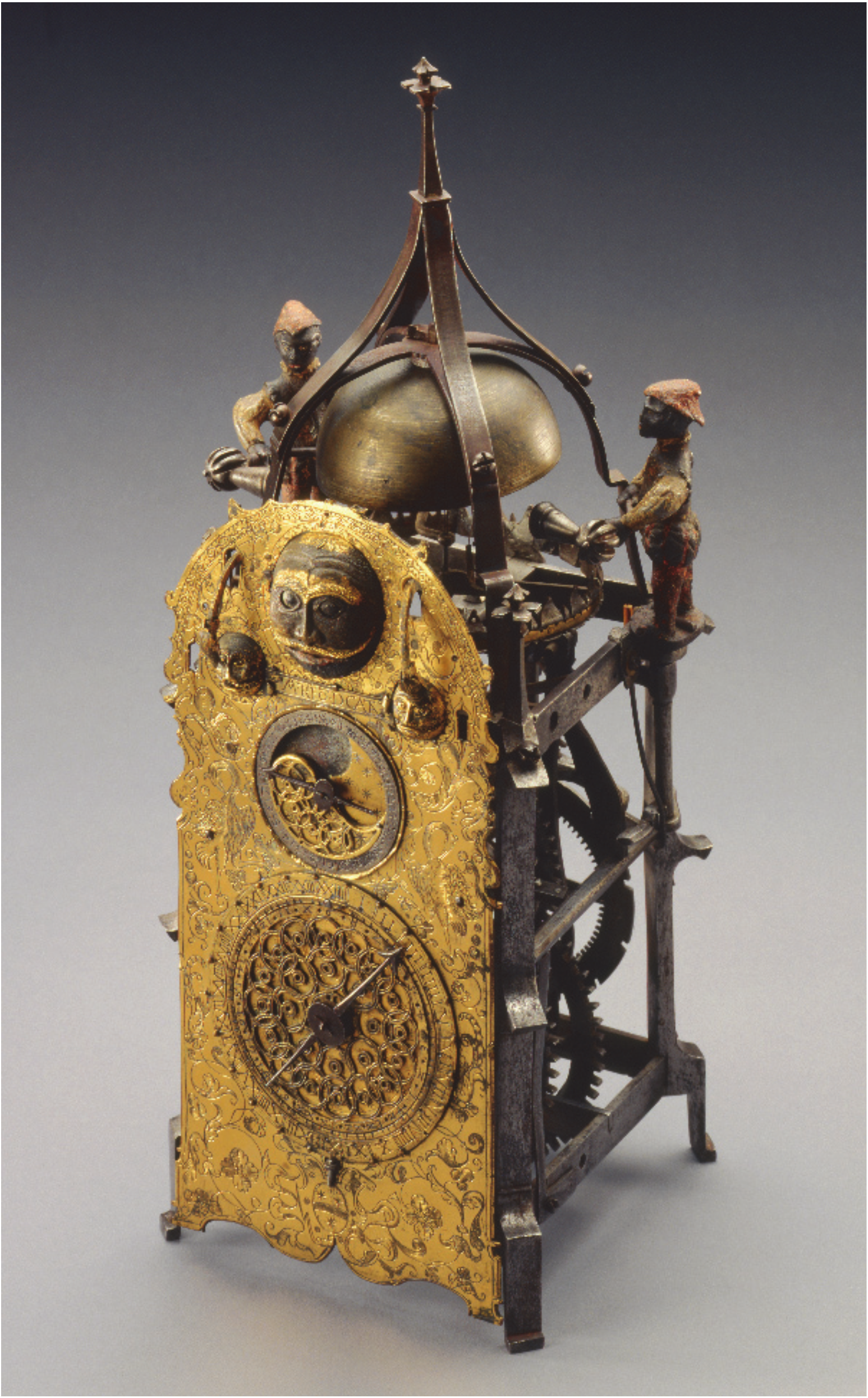
Besides public tower clocks, the verge escapement mechanism was used also for private wall clocks. An amazing example of an animated wall clock mechanism is found in the Milwaukee Art Museum [8]. As the clock strikes each hour, the two small heads on the dial open their mouths and poke out their tongues, and a pair of serpents descend from windows to bite their noses. The larger center head simultaneously drops its lower jaw and moves its eyes continually from side to side. The two bell-ringers dressed as feudal serfs sound the bell (Figure 2).
Clocks with various mechanical dolls, often animated, were quite typical in the Middle Ages. It was reported that Haroun al-Raschid’s master, al-Jazari, built a clock in the form of an elephant bearing a mahout on its neck, a writer on its back, and a howdah with a third figure at a balcony in the front. At the half-hour, a bird on the top of the howdah turned and sang, and the man in the howdah pointed to an eagle which dropped a ball into the mouth of a dragon [3]. Many European tower clocks had figures of carved “jacks” (also called “jacks o’ the clock” or jacquemarts” [2]) striking a bell at an hour.
While early mechanical clocks relied upon the verge-and-foliot mechanism, the first pendulum clock was built only in 1658 CE by Christian Huygens, who used Galileo’s discovery of the isochronicity of small oscillations of a pendulum. The isochronicity of the pendulum, or the independence of the oscillation frequency upon the amplitude, was investigated by Galileo, starting in 1588 CE, and published in 1602 [9]. Galileo also suggested an original escapement mechanism in about 1637; however, he never built this mechanism. Huygens’ pendulum, combined with an anchor escapement, swung for about 6° and provided very high accuracy. A second modified version of Huygens’ clock was built in 1673 and its accuracy was about 10 s per day.
As a consequence of the introduction of the pendulum in 1658, the accuracy of the clocks increased by almost 30 times within the decade. Verge escapement clocks had an error of approximately 300 s per day, while the pendulum and anchor-escapement clocks had an error of about only 10 s per day [5]. In the horological literature, the introduction of the pendulum is viewed as a revolutionary invention, whereas the emergence of the verge-and-foliot escapement mechanism is often treated as an evolutionary development of the clepsydra (water clock) used in Europe, Asia, and the Middle East. For example, the Dar al-Magana clock was built in Fez, Morocco in 1357 CE, and it modeled the 12th century Jayrun water clock in Damascus (Figure 1a). Indeed, sophisticated water clocks had their own type of escapement mechanisms [10]. However, there is also a significant difference between the water and mechanical clocks. The former employed continuous flow to measure time intervals, while the latter used an oscillatory periodic process as a time-measuring device. The escapement in the clepsydra is essentially a water flow meter. While the transition of technical and astronomical knowledge from the Muslim world played a significant role in many aspects of the European Renaissance, such as the emergence of the Copernican heliocentric theory [11], there is no evidence of such influence with the verge escapement mechanism, which appeared at first in Europe. Therefore, early mechanical clocks with the verge-and-foliot escapement mechanism constitute a technological leap which requires thorough investigation.
The verge mechanism is not unknown in the literature on mechanical vibrations [10,12,13,14,15,16,17]. A model of a verge escapement mechanism was presented in the vibrations textbook by Andronov et al. [1,17]. The verge mechanical clock was also studied by control engineers as an example of an early feedback mechanism. Thus, Lepschy et al. [10] compared the feedback loop of the verge escapement mechanism with that of the Ktesibios’ water clock (c. 230 CE). Roup and Bernstein investigated limit cycles of the verge escapement mechanism [15]. However, the question of why the accuracy of the verge escapement mechanism remains so low in comparison with the pendulum-based clock has not been addressed in most of these studies. Headrick [12] stated that “the greatest problems were caused by changes in temperature and levels of friction”; however, he suggested no quantitative analysis.
Modern studies of friction have significantly advanced the understanding of the role of friction and lubrication in bearing mechanisms [18]. In particular, it has been established that even small variations of friction could cause, under certain conditions, a significant effect on the performance. Moreover, they can even induce dynamic instabilities and can cause self-excited vibrations [19].
In the present paper, we investigate this matter using a mathematical model for verge oscillations. We will study mathematically the effect of friction on the accuracy of both mechanisms: the verge and foliot escapement and the pendulum. We will also discuss its application to numerical modeling and to some known historical clocks.
2. Mechanics of the Verge and Pendulum Mechanisms
A schematic of the verge escapement mechanism is presented in Figure 3 along with a corresponding kinematic diagram. The verge escapement mechanism involves a crown wheel with saw-like teeth driven by a weight. The crown wheel alternately hits the two pallets fastened to the verge shaft with about 100° of angular separation. The verge is also connected with a bar called a foliot with adjustable weights on its ends. The revolving motion of the crown wheel causes an alternating circular movement of the foliot. A push on the upper pallet results in a rotatory movement in one direction (clockwise), whereas a push on the lower pallet results in a rotatory movement in the opposite direction (counterclockwise). The two movable weights hanging from the foliot allow for adjusting its moment of inertia. The pallets rotate by about the angle of during the operation.
When a tooth of the crown wheel escapes, this wheel rotates freely by the “drop” Δθ of about 2° until another tooth strikes the other pallet an instant later. When the other pallet hits the tooth, the foliot stops and changes direction, since the crown wheel continues to exert a force on the pallet, continuing to do so until it has rotated by about 100° and the pallet allows the tooth to escape again. The periodic process continues indefinitely.
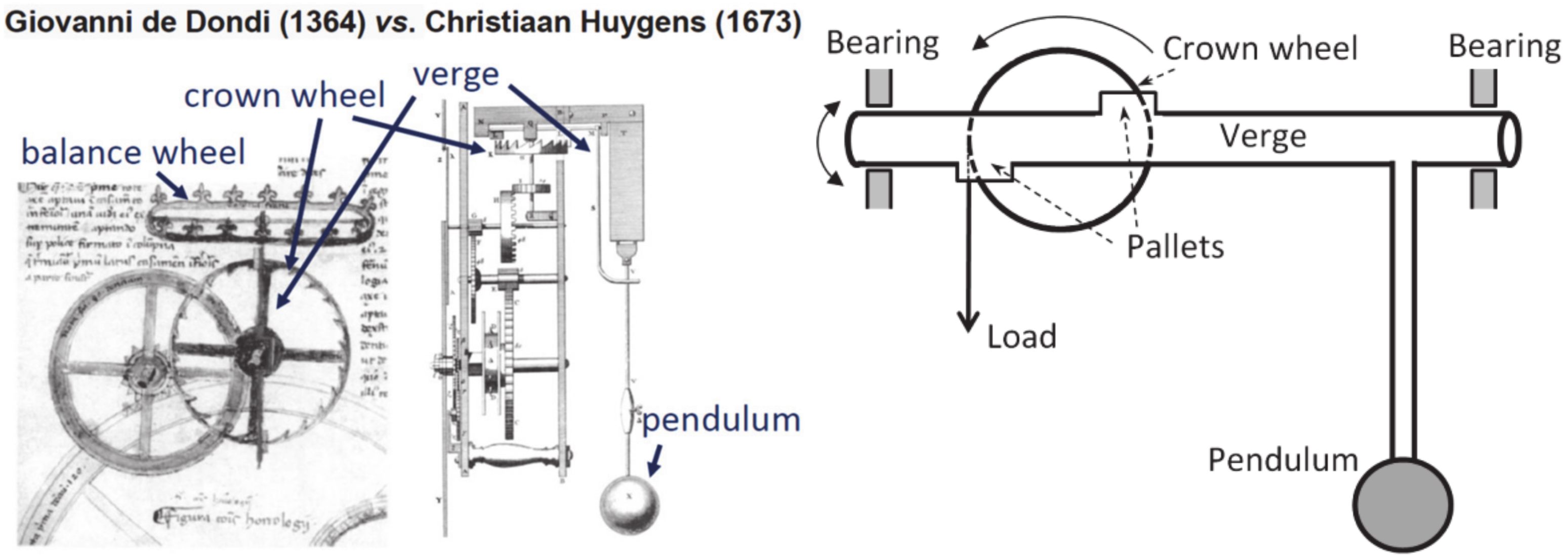
Another version of the verge escapement mechanism (with the balance wheel instead of the foliot) is presented in Figure 4. It is also compared with an early pendulum mechanism, with corresponding kinematic diagrams. This early pendulum mechanism is the second modified version of Huygens’ clock, which was built in 1673. The accuracy of the clock was about 10 s per day, which was a great improvement (about 30 times) in comparison with the verge mechanism. From a mechanician’s viewpoint, the pendulum mechanism is an almost harmonic oscillator with a certain natural frequency, which serves as a basis for time measurement.
Note that both mechanisms involved simple journal bearings, which could result in considerable friction. Moreover, friction is generally coupled with wear. These two effects are often even viewed as two sides of the same phenomenon of the irreversible nature of sliding contact: while friction is the energy dissipation, wear is material deterioration during sliding [18]. It is not surprising that parts of the mechanism required frequent replacement.
While an ideal oscillator should not involve any friction, practically speaking, some friction is inevitable. This is because one or another type of ratcheting or escapement mechanism should be used in order to measure motion. According to modern theories of friction, friction is a manifestation of irreversibility, which, in turn, is the consequence of the second law of thermodynamics [18,19]. It is not surprising that measuring time involves a dissipative mechanism.
3. Mathematical Model of the Verge Escapement Mechanism
In this section, we will discuss a mathematical model of the verge escapement mechanism both without a pendulum and with a pendulum. After that, we will investigate the accuracy of both mechanisms by relating the period of oscillations to friction using simple scaling arguments.
3.1. Simple Verge-Foliot Escapement
The motion of the verge escapement mechanism consists of six separate phases:
1. The crown wheel and the verge rotate in the same direction with the angular acceleration of
where T is the torque exerted on the verge by the weight, JC and JV are the moments of inertia of the crown wheel and the verge-foliot, and θ and are the rotation angles of the crown wheel and the verge, respectively. The values of and correspond to the two pallets hitting the teeth, so that .
2. The free motion (drop) of the verge and the acceleration of the crown wheel until it moves for the distance of Δθ and hits the verge:
3. The tooth hits the second pallet. An elastic or inelastic collision can occur. Typically, it is assumed that the collision is inelastic. This implies that while the total angular momentum is conserved after the collision, the angular velocities are
Note that the energy dissipation—due to either the inelastic collision or friction—is essential for the verge escapement mechanism, and it should always be included in the model. This is because without the dissipation the mechanism would continuously accelerate instead of providing a constant rate of motion.
4. The opposite motion of the crown wheel and the verge
5. The drop of the verge in the opposite direction and acceleration of the crown wheel:
6. The tooth hits the first pallet.
The above model does not take friction into consideration; however, a constant frictional torque, f, opposing the rotation of the crown-wheel can be easily added to the system by modifying the total torque as .
The total period of oscillation is equal to the sum of the durations of all six phases:
where , , while τ3 = τ6 are small yielding the period of oscillations
3.2. Verge with Attached Pendulum
The model can be further extended for the case of the motion of the verge with the pendulum attached with the restoring torque of . The six phases are then given by
1. The crown wheel and the verge rotate in the same direction
2. The free motion of the verge
3. The tooth hits the second pallet.
4. The opposite motion of the crown wheel and the verge
5. The drop of the verge in the opposite direction and the acceleration of the crown wheel:
6. The tooth hits the first pallet.
3.3. Effect of Friction on Clock Accuracy
Using the approach of the previous section, the dependency of the period of vibration on friction can be evaluated. The motion of the mechanism with a pendulum with friction can be simplified by considering phases 1 and 4, mostly contributing to the period of oscillations. Then, Equations (9) and (12), with account of friction, can be presented as
where is the restoring torque, f is the frictional torque, T is the torque from the escapement mechanism, and n is the number of a pallet in contact (either the first or the second). Following Andronov et al. [17], a dimensionless form can be used
where the following non-dimensional variables are used.
Note that in many cases frictional torque is smaller than the applied torque, , and thus . The ratio of the frictional and applied torque can also be viewed as the coefficient of friction in the system, .
There are two different cases, which lead to different behaviors of the oscillating system.
For , the non-dimensional time variable is selected as
and we immediately obtain , and the period of vibration for r = 0 is given by , while for the period of vibrations linearly depends on friction
or, in real time units
where C is a proportionality constant on the order of the unity.
On the other hand, for (no pendulum), Equation (18) cannot be used, and a different non-dimensional time variable is defined as
Hence , , and the period of vibration is given by Equation (8), which yields
In real time units
A comparison shows that a system with a pendulum is much less dependent on the variation of friction. For example, the variation of the coefficient of friction (and a proportional variation of the frictional torque) by one percent from μ = 0.1 to μ = 0.101 would result in a corresponding change in the period of vibration by 0.5% or 432 s per day. For comparison, changing the frictional-to-driving torque ratio from f/T = 0.1 to f/T = 0.101 would result in the change of the non-dimensional period of vibration from τ = 6.183 to τ = 6.182, or by only 0.016% or 14 s per day.
Assuming the value of the coefficient of friction (which is reasonable for a lubricated mechanism) and C = 1 in Equation (19), the improvement due to the introduction of the pendulum can be estimated as a ratio of the derivatives of the vibration periods given by Equations (20) and (23) by μ divided by the ratios of the corresponding time periods
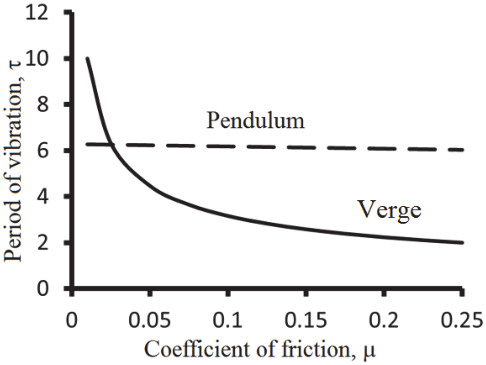
The value supplied by Equation (24) is consistent with the literature statements that the introduction of the pendulum between 1658 and 1673 resulted in the improvement of the accuracy of the clock by 30 times [5]. Typical dependencies of the period of oscillation on the coefficient of friction for the verge (solid) and pendulum (dashed) mechanism based on Equations (20) and (23) are shown in Figure 5. It is observed that the mechanism without a pendulum is much more sensitive to the change in friction.
Mathematically, the isochronicity is a property of the linear operator
where A(ω) is a matrix involving the stiffness and mass matrices, K and M, while X is a column of amplitudes. A linear combination of solutions of Equation (25) is also a solution. If column Xn is a solution (an eigenvector of amplitudes) corresponding to an eigenvalue ωn (a natural frequency), then the same column multiplied by a constant is also a solution. Therefore, in a linear system, the natural frequency does not depend on the amplitude. For nonlinear systems, the frequency of oscillations may depend on their amplitude, and the general motion cannot be presented as a superposition of eigenvectors.
Galileo’s discovery of linear systems, along with the astronomical observations by Galileo, Kepler and Newton that the motion of planets in the Solar System can be decoupled as a combination of two-body problems, had far-reaching consequences for the history of physics in the early modern period. These discoveries strengthened the reductionist method of establishing the laws of nature from the observations of parts of a system, whose behavior is independent of their context. Wiltsche [20] pointed out that pre-Galilean Aristotelian mechanics studied natural occurrences as opposed to the study of phenomena (“the invariant forms that allegedly underline natural occurrences”) introduced by Galileo. The latter systematically excluded causal accidents as impediments, and friction was often ignored and neglected in the search of refined and purified phenomena [21].
4. Numerical Modeling of Historical Clocks
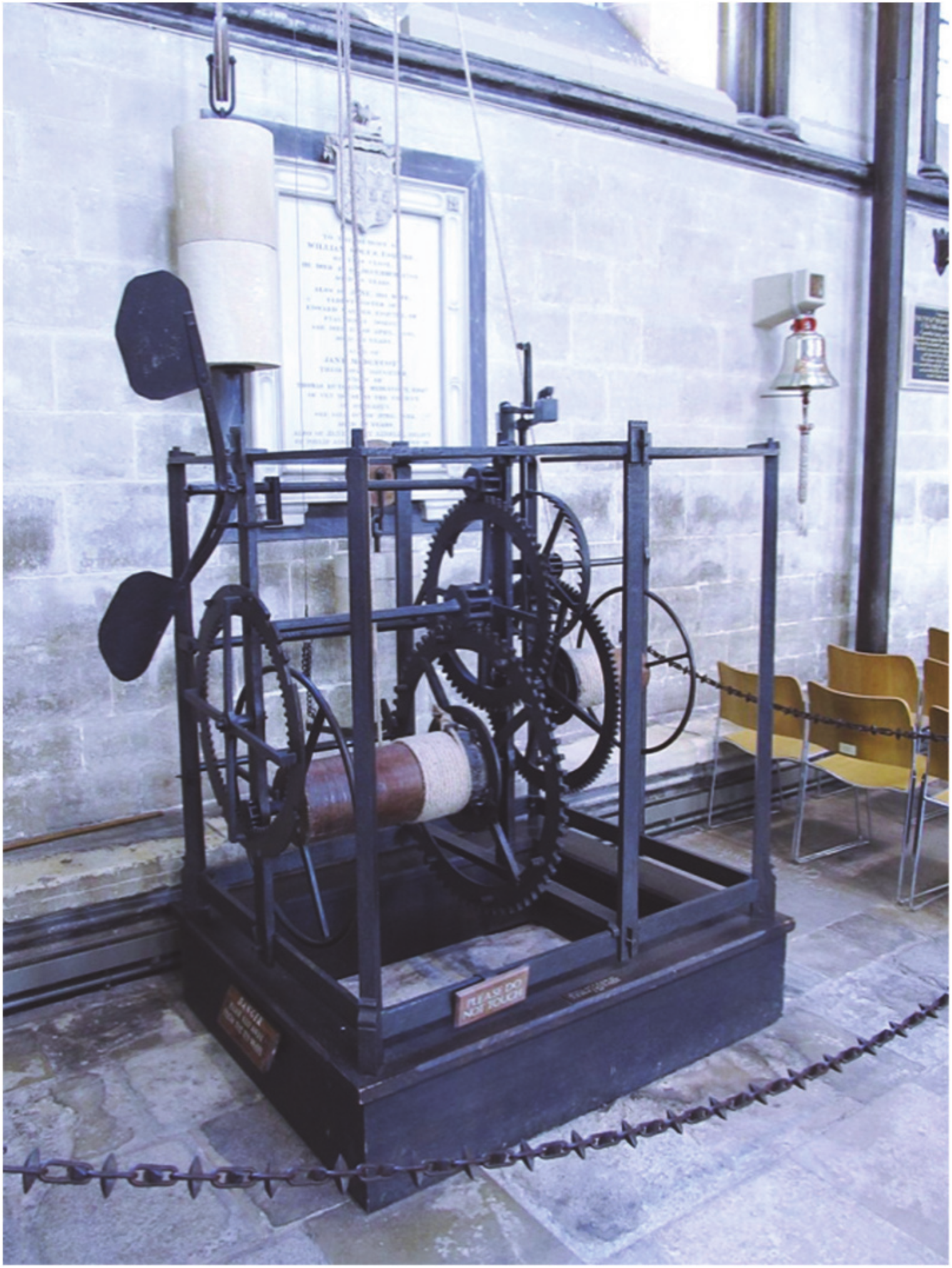
An interesting case study is the clock in Salisbury Cathedral in Wiltshire Co., England (Figure 6). This is purportedly the oldest working clock with a verge-foliot escapement mechanism [4]. The mechanism originated from 1386; however, it had been lost for four decades before being found again in 1928. At this point, the mechanism had had a pendulum installed, while the verge and foliot had been removed. No documentation of the previous verge and foliot could be found, but a replacement version was created in 1956 and installed to return the clock to its original condition and method of time keeping.
In order to ensure that the crown gear and the pallets of the verge will engage, the following relation between the crown wheel and verge radii must be met
where n is an odd number equal to the number of teeth, and is the angle between the pallets.
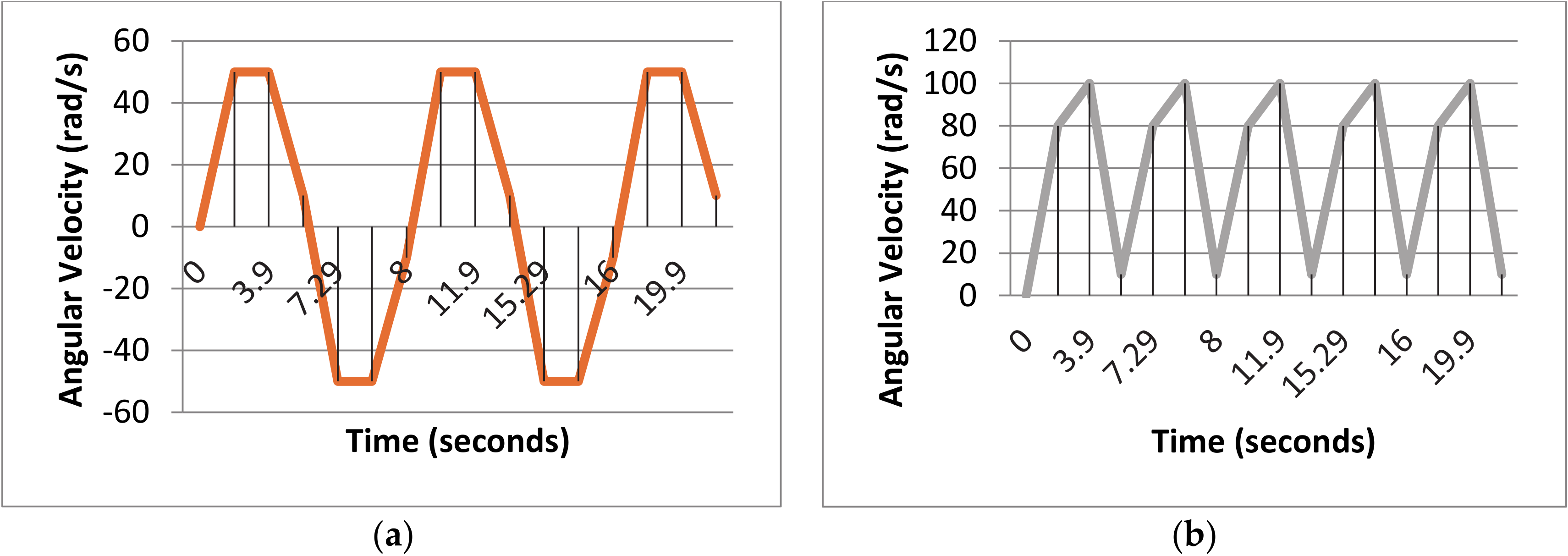
Using measurements from a picture of the clock and scaling it in a CAD program to the given outside dimensions of 1.24 m in height by 1.29 m in width and 1.06 m in depth, we get s, and, therefore, s, which is close to the actual period of the clock at 8 s. The dependency of the crown-wheel and verge velocities during the operation of the clock is shown in Figure 7.
5. Conclusions
The invention of the oscillating verge and foliot escapement mechanism at the end of the 13th century was a breakthrough in the development of time measuring technology. It resulted in the emergence and rapid proliferation of mechanical tower clocks and, later, wall clocks in Europe. While the exact circumstances of this invention are unknown, it happened almost simultaneously with the emergence of sandglasses, which was likely stimulated by two factors: the development of marine technology and changing attitudes towards the organization of time during the early Renaissance.
Friction played an important role in the operation of the verge and foliot escapement mechanism. Energy dissipation due to friction and the inelastic collision verge pallets with the crown wheel is essential for the mechanism, because without the dissipation, the mechanism would accelerate. However, the frequency of oscillations of the verge and foliot escapement mechanism is very sensitive to friction. Small variations in the coefficient of friction, μ, may result in a significant change in the period of oscillations, thus affecting the clock’s accuracy. This is because the verge and foliot mechanism does not have its own natural frequency, and the period of oscillations scales as a power of −1/2 of the forces acting upon the mechanism including the friction force.
The pendulum mechanism introduced in 1658 by Huygens had its own natural frequency, with friction having only a minor effect on the period of oscillations. Scaling arguments suggest that the clocks’ accuracy improved by a factor of the order of π/μ, or by about 30 times, which is consistent with actual historical data. The invention of the pendulum can be viewed in the broader context of the scientific revolution of the 17th century as a success of the reductionist paradigm of the natural philosophy associated with Galileo and Newton, when simple linear phenomena (linear oscillations, two-body gravity problems, etc.) were identified to explain the behavior of complex systems.
Author Contributions
The original concept, supervision, and writing by M.N.; figures and calculations by A.S.B. All authors have read and agreed to the published version of the manuscript.
Funding
This research received no external funding.
Conflicts of Interest
The authors declare no conflict of interest.
References
- Healey, J.F. A Nabatean Sundial from Mada’in Salih. In Syria: Revue d’art Oriental et D’archéologie; LXVI: Paris, France, 1989; pp. 331–336. [Google Scholar]
- Brearley, H.C. Time Telling through the Ages; Page &, Co.: Doubleday, NY, USA, 1919. [Google Scholar]
- Burton, E. The History of Clocks and Watches; Rizzoli: New York, NY, USA, 1979. [Google Scholar]
- Britten, F.J. Old Clocks and Watches and Their Makers, 7th ed; Bonanza Books: New York, NY, USA, 1956. [Google Scholar]
- Cipola, C. Clocks and Culture 1370–1700; Walker and Co.: New York, NY, USA, 1967. [Google Scholar]
- Dubois, P. De Vick tower clock, built Paris, 1379, by Henri de Vick. In Historie de l’ Horlogeri; Maxtor: Paris, France, 1849; p. 221. [Google Scholar]
- Balmer, R.T. The operation of Sand Clocks and their medieval development. Technol. Cult. 1978, 19, 615–632. [Google Scholar] [CrossRef]
- Winters, L. A Renaissance Treasury: The Flagg Collection of European Decorative Arts and Sculpture; Hudson Hills Press: New York, NY, USA, 1999; p. 26. [Google Scholar]
- Drake, S. Galileo at Work: His Scientific Biography; University of Chicago Press: Chicago, IL, USA, 1978; p. 419. [Google Scholar]
- Lepschy, A.M.; Mian, G.A.; Viaro, U. Feedback Control in Ancient Water and Mechanical Clocks. IEEE Trans. Educ. 1992, 35, 3–10. [Google Scholar] [CrossRef]
- Nosonovsky, M. Abner of Burgos: The missing link between Nasir al-Din al-Tusi and Nicolaus Copernicus? Zutot 2018, 15, 25–30. [Google Scholar] [CrossRef]
- Headrick, M.V. Origin and evolution of the anchor clock escapement. Control Syst. 2002, 22, 41–52. [Google Scholar] [CrossRef]
- Mao, J.; Fu, Y.; Li, P. Dynamics of Periodic Impulsive Collision in Escapement Mechanism. Shock Vibr. 2013, 20, 1001–1010. [Google Scholar] [CrossRef]
- Petrangeli, G. Mathematics of a Clock Escapement; Prod. University of Pisa: Rome, Italy, 2013. [Google Scholar]
- Roup, A.; Bernstein, D.S. On the dynamics of the escapement mechanism of a mechanical clock. In Proceedings of the 38th IEEE Conference on Decision and Control, Phoenix, AZ, USA, 7–10 December 1999; pp. 2599–2604. [Google Scholar]
- Wagner, J.; Moline, D.; Vold, E. Model of a Mechanical Clock Escapement; Clemson University TigerPrints (American Association of Physics Teachers): Clemson, SC, USA, 2012; pp. 590–606. [Google Scholar]
- Andronov, A.A.; Vitt, A.A.; Khaikin, S.E. Theory of Oscillators; Dover Publications, Inc.: New York, NY, USA, 1966. [Google Scholar]
- Menezes, P.L.; Nosonovsky, M.; Ingole, S.P. Tribology for Scientists and Engineers; Springer: New York, NY, USA, 2013. [Google Scholar]
- Nosonovsky, M.; Mortazavi, V. Friction-Induced Vibrations and Self-Organization; CRC Press: Boca Raton, FL, USA, 2013. [Google Scholar]
- Wiltsche, H.A. Mechanics lost: Husserl’s Galileo and Ihde’s telescope. Husserl Stud. 2017, 33, 149–173. [Google Scholar] [CrossRef] [Green Version]
- Nosonovsky, M.; Breki, A. Ternary Logic of Motion to Resolve Kinematic Frictional Paradoxes. Entropy 2019, 21, 620. [Google Scholar] [CrossRef] [Green Version]
Figure 1.
Earlier clocks. (a) A 1st century CE Nabatean sundial from Mada’in Salih (Hejaz, Saudi Arabia), with the name of the owner mnš br ntn šlm (“Menashe son of Nathan, peace” [1]), Istanbul Archeological Museum, Inv. 7664. (b) Dar al-Magana clock (Fez, Morocco), built in 1357 CE. Both photos by the author (M.N.).

Figure 2.
Wall Clock with Automation, Southern Germany 1550/1600. Iron, bell metal, brass, gilt copper, and polychrome decoration 35.56 × 15.24 × 16.51 cm. Milwaukee Art Museum, Purchase, with funds in memory of Betty Croasdaile and John E. Julien M2002.182. Photographer credit: John Nienhuis.
Figure 2.
Wall Clock with Automation, Southern Germany 1550/1600. Iron, bell metal, brass, gilt copper, and polychrome decoration 35.56 × 15.24 × 16.51 cm. Milwaukee Art Museum, Purchase, with funds in memory of Betty Croasdaile and John E. Julien M2002.182. Photographer credit: John Nienhuis.

Figure 3.
A schematic and a kinematic diagram of the verge-and-foliot escapement mechanism from the 1379 Henri De Vick tower clock in Paris.
Figure 3.
A schematic and a kinematic diagram of the verge-and-foliot escapement mechanism from the 1379 Henri De Vick tower clock in Paris.

Figure 4.
A verge escapement in Giovanni de Dondi’s clock (1364, Padua). A balance wheel was used instead of a foliot; drawing from his Il Tractatus Astrarii (left). A schematic and a kinematic diagram of the second pendulum clock built by Christiaan Huygens (1673); drawing from his Horologium Oscillatorium (right).

Figure 5.
Typical dependencies of the period of oscillation on the coefficient of friction for the verge (solid) and pendulum (dashed) mechanism.
Figure 5.
Typical dependencies of the period of oscillation on the coefficient of friction for the verge (solid) and pendulum (dashed) mechanism.

Figure 6.
Salisbury Cathedral clock mechanism.

Figure 7.
Angular velocities of the (a) verge foliot and (b) crown gear over time. In each chart, the delineation between each part of the period can be seen.
Figure 7.
Angular velocities of the (a) verge foliot and (b) crown gear over time. In each chart, the delineation between each part of the period can be seen.

© 2020 by the authors. Licensee MDPI, Basel, Switzerland. This article is an open access article distributed under the terms and conditions of the Creative Commons Attribution (CC BY) license (http://creativecommons.org/licenses/by/4.0/).
Share and Cite
MDPI and ACS Style
Blumenthal, A.S.; Nosonovsky, M. Friction and Dynamics of Verge and Foliot: How the Invention of the Pendulum Made Clocks Much More Accurate. Appl. Mech. 2020, 1, 111-122. https://0-doi-org.brum.beds.ac.uk/10.3390/applmech1020008
AMA Style
Blumenthal AS, Nosonovsky M. Friction and Dynamics of Verge and Foliot: How the Invention of the Pendulum Made Clocks Much More Accurate. Applied Mechanics. 2020; 1(2):111-122. https://0-doi-org.brum.beds.ac.uk/10.3390/applmech1020008
Chicago/Turabian StyleBlumenthal, Aaron S., and Michael Nosonovsky. 2020. "Friction and Dynamics of Verge and Foliot: How the Invention of the Pendulum Made Clocks Much More Accurate" Applied Mechanics 1, no. 2: 111-122. https://0-doi-org.brum.beds.ac.uk/10.3390/applmech1020008