1. Introduction
It is the shipper’s responsibility to provide cargo units with a special substructure (a cradle or trestle, for example) for heavy shipments. Both elements must be secured together (as a unique block) to ensure that the transport is carried out in safe conditions, because the measurements of transverse, longitudinal, and vertical accelerations are much higher than those produced in road or rail transport [
1].
On the other hand, it is the responsibility of the carrier (or to whomever the task is delegated) to provide a bedding where the cargo footprint can rest in order to absorb all forces (gravity, inertia, and external forces of wind and sea sloshing), acting on the cargo units and transferring them to the ship’s deck without suffering deformation. For this objective, it is necessary to design and construct special beddings ergonomically adapted for heavy cargo units and with adequate strength to resist the forces sustained during sea transport [
1,
2,
3].
The main objective of this paper is to carry out a comparative study between the IMO CSS Code and DNV·GL—one of the strictest classification societies—to place relevance on items that should be reconsidered by the IMO in sea transport of heavy cargo units. This is because many shipping, lashing, and stevedoring companies make use of the IMO guidelines by default, without taking into account, many times, the particularities of the cargo, voyage, and even, economic aspects.
Although Jiang et al. [
4] analyzed the impact of horizontal securing angle (β) after being implemented in the CSS Code by the IMO almost 30 years after its entry, taking into consideration project cargoes transported nowadays, a new amendment could be looked into.
In May 2019, the IMO included in the 6th session of the Sub-Committee on Carriage of Cargoes and Containers CCC6/7, the “Amendments to the CSS Code with regard to weather-dependent lashing” [
5]. It remains to be seen if this proposal will be finally approved and if concrete formulas will be provided to users. Therefore, if this issue were specified, there might be a new field of research. Some operators, e.g., Dockwise Shipping B.V [
6], have tried to divide the globe into different meteorological areas in order to plot an optimum route for heavy-lift vessels, without widespread application.
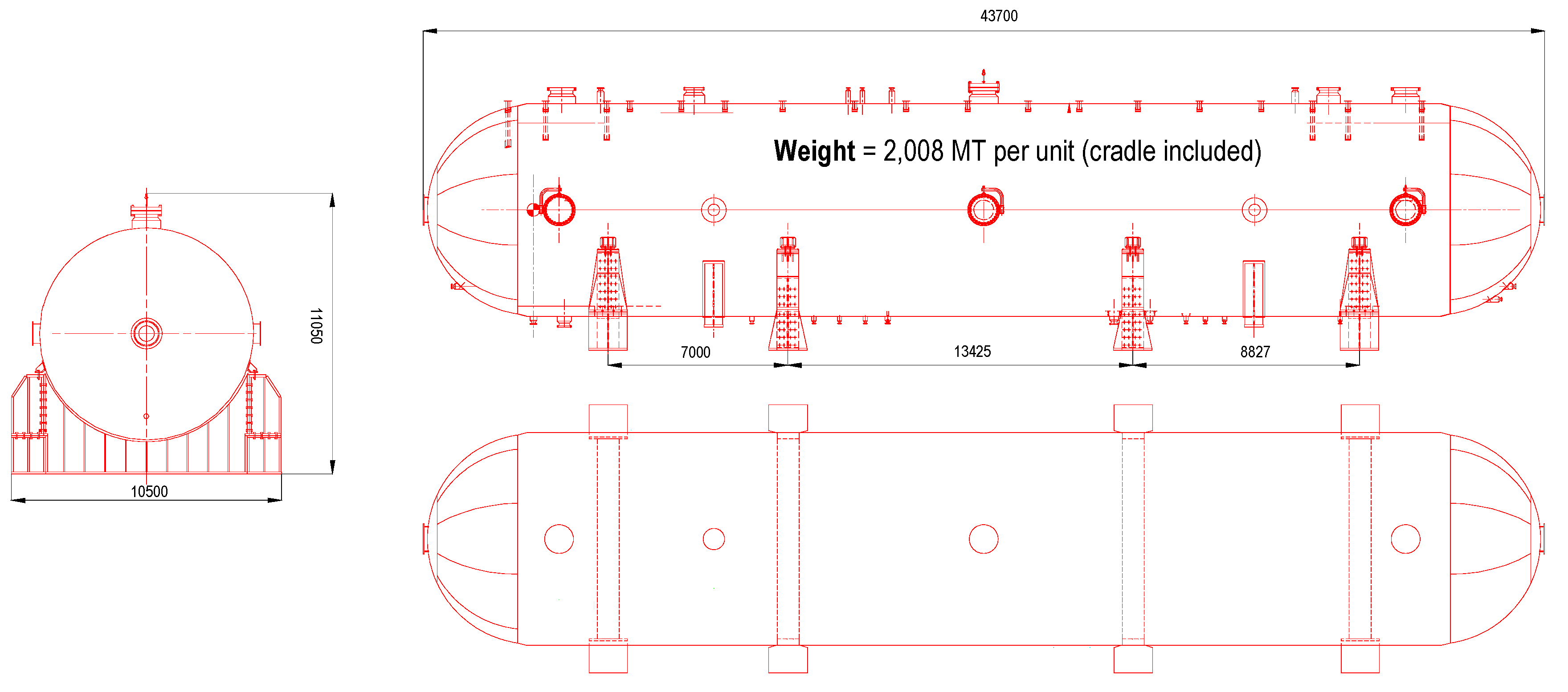
For this, gas slug catchers (GSCs) are used in a paradigmatic case, where the grillage for three GSCs is designed to be transported by sea (see
Figure 1). The GSCs have a cylindrical shape, so the cradles attached to each cargo unit body are used for loading and unloading operations by a self-propelled modular transporter (SPMT), a special type of trailer used for heavy project cargo [
7]. Once in stowage position, they are supported by corresponding bedding (grillage beams). The grillage transfers all the forces onto a greater stowage area or onto the ship main girders/frames so that the permissible loading area of the ship’s structure is not exceeded [
1,
8].
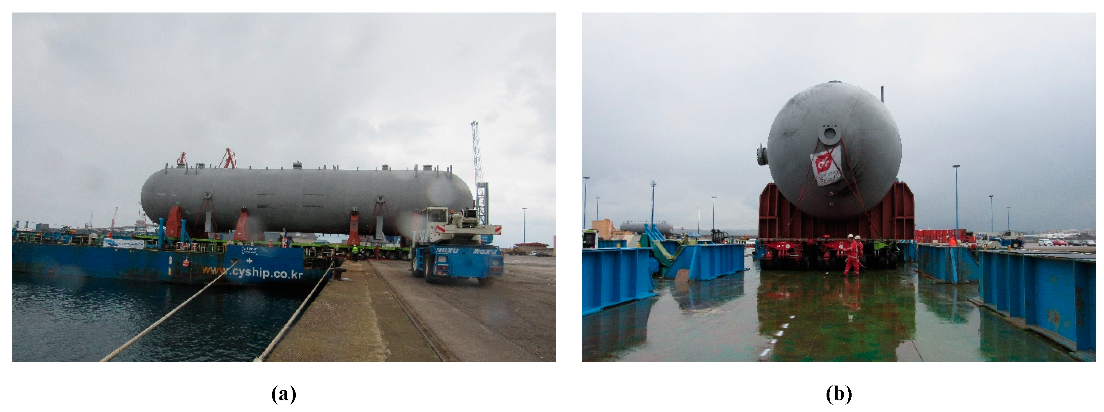
Loading operations of one gas slug catcher can be observed from different points of view in
Figure 2.
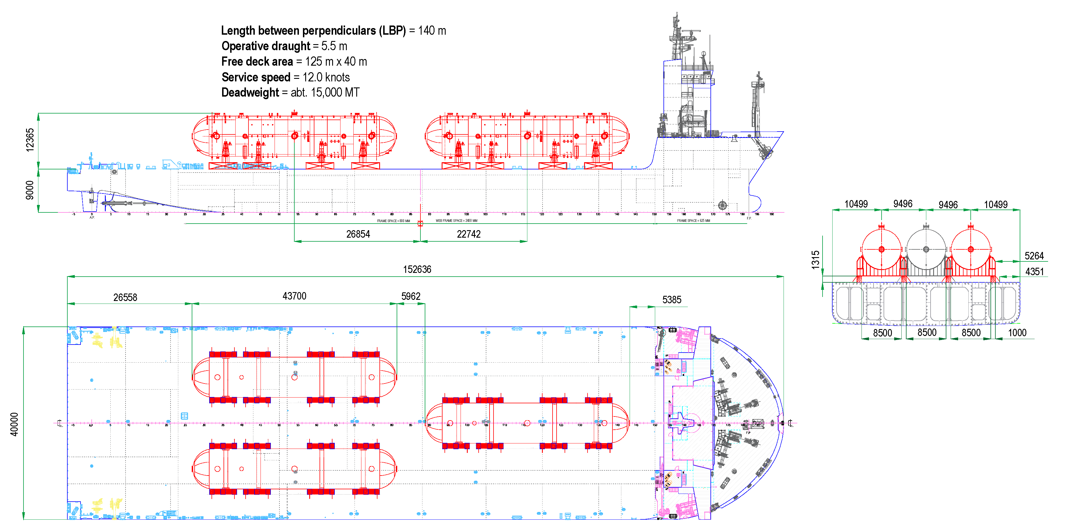
Sea transport from Gijon to Jubail is carried out by CY INTEROCEAN II, which was launched in 2017. The vessel is an ocean deck carrier specifically designed for heavy cargo units, with the cargo deck heavily reinforced by girders and frames. These supports offer a strength of 20 MT·m
−2, unlike other vessels that usually have a maximum weather deck strength of around 2.5–3 MT·m
−2 [
1,
8,
9,
10]. CY INTEROCEAN II does not have cargo holds or hatch covers (
Figure 3 shows the ship’s particulars and the stowage plan).
Vessels with such particulars face a series of difficulties when calculating accelerations as per the CSS Code. The relatively small number of ships with these dimensions means that the state of the art is not as abundant as it is with other ship types such as containers or pure Ro-Ro vessels [
11,
12,
13].
2. Numerical Methods
2.1. Initial Approach
For numerical calculations, we started from the premise that each GSC is supported by four transport cradles provided by the shipper as a joint part of the cargo unit. Each cradle rests on two substructures (bedding), symmetrically placed at the centre of gravity of the GSC as practicable as possible (from now on called the grillage beam/girder).
The data used for calculations are the self-weight of the GSC plus the weight of the four transport cradles. Theoretically, each of the four transport cradles supports 502.0 MT (4922.96 kN), but, as they are rigid metal structures, ergonomically adapted to the GSC circular bottom and distributed along its length, in practice, all cradles transfer different forces as a result. Therefore, it is considered that one cradle transfers a force 5.5% higher than others do; in this case, approximately 529.5 MT (5192.65 kN) [
14].
Due to rolling and pitching ship motions, the gravity forces were broken down into transversal and longitudinal components [
8]. Furthermore, the inertia (dynamic) forces on the cargo units because of changes in direction and speed of the three ship movements (pitch and roll as rotation motions, and heave as linear motion) were taken into account.
2.2. Calculation of Accelerations and Forces as per DNV·GL Guidelines
Considering the ship particulars and the cargo dimensions, the design accelerations were calculated as per DNV·GL guidelines [
2,
3].
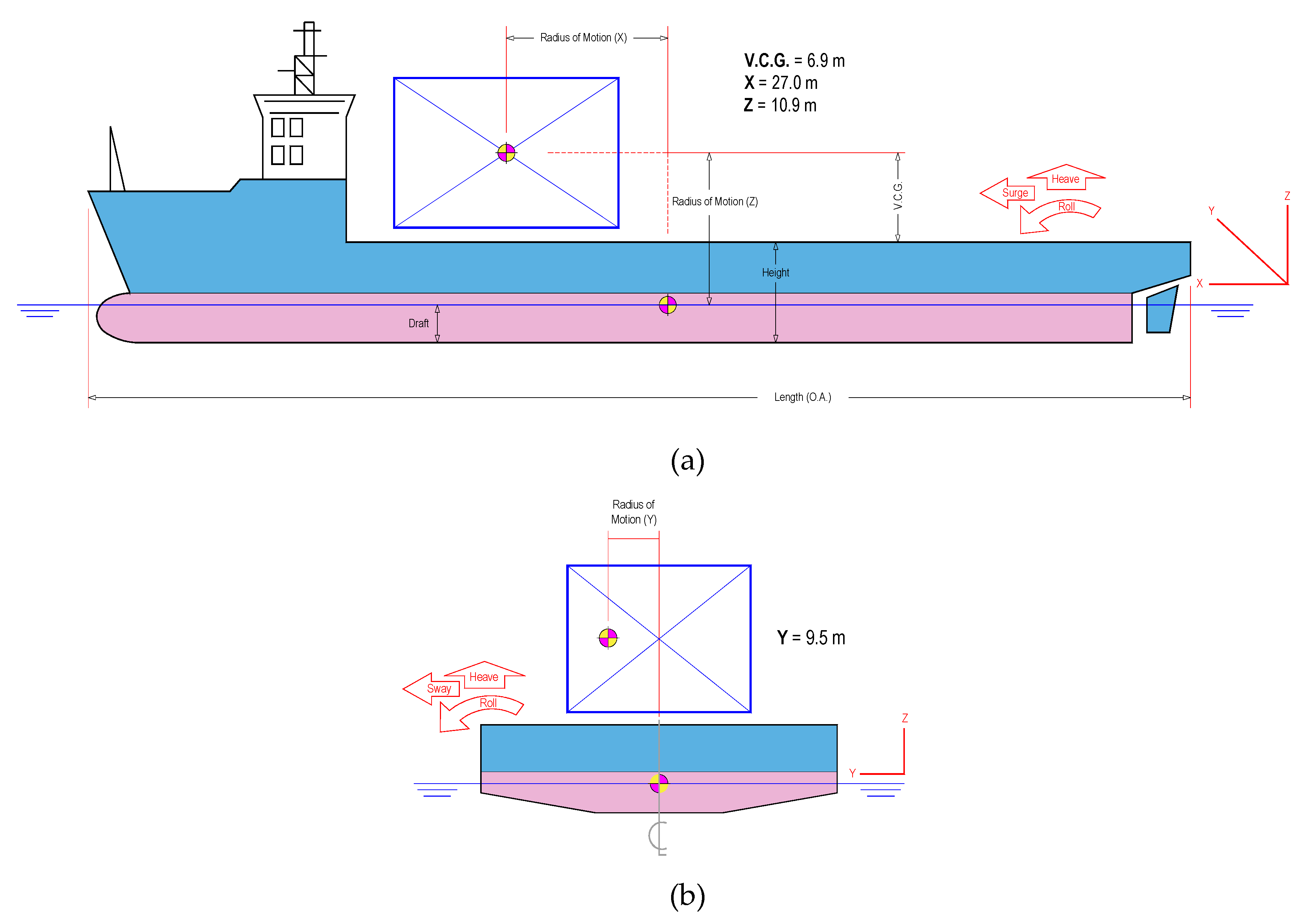
In order to define the radius of motion, we started from the GSC’s position in the stowage plan so as to consider the most unfavourable GSC situation regarding the ship roll motion. The aft stowed GSCs were taken for the radius of motion (X), and one of them on the port or starboard side was taken for the radius of motion (Y). The radius of motion (Z) was the same for all three GSCs (see
Figure 4).
The reference values of roll, pitch, and heave are based on default motion criteria of DNV·GL Noble Denton, considering a nature of transportation unrestricted [
2]. This document was updated after the fusion between GL Noble Denton and DNV and, although it has been replaced by the standard DNVGL-ST-N001, it still remains valid for some existing projects [
3].
Table 1 shows the amplitude and the period of rolling and pitching of the ship to the selected motion case, where the heave acceleration is 0.2 g (1.96 m·s
−2).
The maximum angular accelerations of rolling and pitching are [
8,
15]
The simple and uncorrelated angular accelerations are
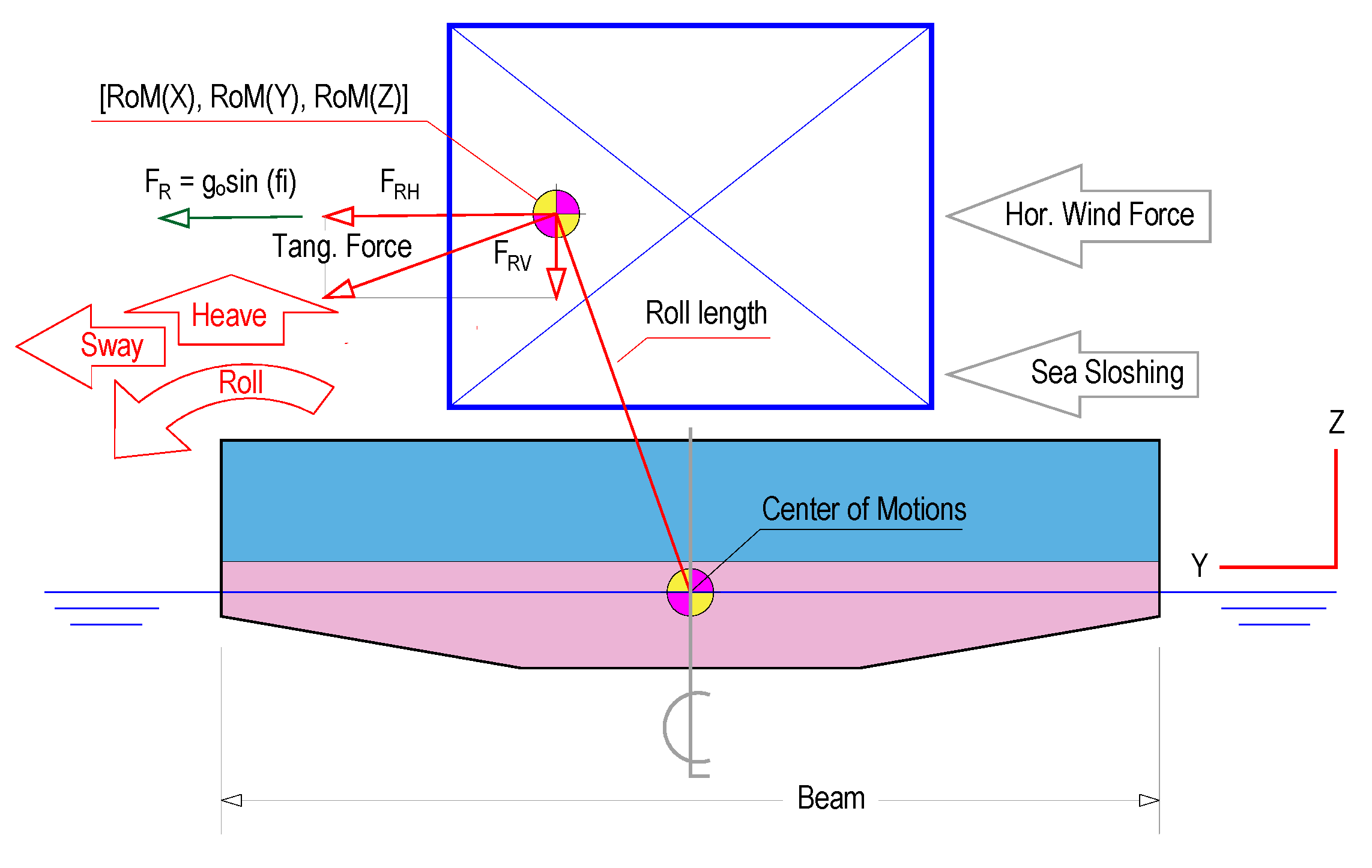
By looking into
Figure 5, one can observe the breakdown of the forces during a rolling motion.
Table 2 shows the corresponding breakdown of transport accelerations, knowing that
where the radius of rotation used in Equation (5) is the roll and the pitch length, which can be calculated by the Pythagorean theorem (planes X–Z and Y–Z).
In the rolling and pitching motions, the horizontal (Y for rolling and X for pitching) and the vertical (Z) components of the tangential acceleration are resolved using the sine and cosine laws of planar triangles.
Furthermore, when the GSCs are out of equilibrium, the gravity originates the following horizontal components:
The breakdown of forces sustained by the cargo unit during the intended seagoing passage is shown in
Table 3:
As the GSCs are stowed on deck, the impact forces generated by wind and water spray were taken into account [
8]. This calculation method considers the water spray effect up to two metres above the cargo deck and the wind force over the cargo exposed entire surface, 90 km·h
−1 (25 m·s
−1) being the highest wind speed expected.
As per DNV Environmental Conditions 2017, the wind force is calculated as follows [
16]:
where
C denotes the cargo shape coefficient (0.5),
q is the basic wind pressure (383.125 Pa),
SW represents the cargo area normal to the wind direction, in longitudinal (X) or transversal (Y) directions, and α is the angle between the wind direction and the axis of the exposed surface. Although the maximum height of the GSC is 11.05 m, to take into account the approximate height of the grillage, 12 m high was considered for the S
W calculation.
The water spray force is
where
LS represents the cargo length normal to the direction of the sea sloshing,
K is a constant (2 meters high above weather deck influenced directly by the water spray), and
P denotes the pressure (0.1 ton·m
−2).
The final results of forces to be countered by securing arrangements are
The combined accelerations generated by the ship motions and supported by the grillage beam are the following:
2.3. Calculations of Accelerations and Forces as per the CSS Code
Nowadays, in many numerical calculations for assessment of securing arrangement, the Annex 13 of the IMO CSS Code is the used standard based on which it is possible to ascertain that a project cargo unit is properly stowed and secured, in order to resist the high accelerations and forces produced during a seagoing passage [
8].
The CSS Code, implemented and successfully used despite not being mandatory, was triggered as a consequence of accidents because the cargo on board was not stowed and secured properly. In fact, it is almost instinctively used for securing arrangement in many non-standardised shipments, although it is not accurate for cargo units with “
unusual characteristics” [
10,
17]. Therefore, having such extraordinary particulars of weight and dimensions in the present shipment, there were several compromising situations that did not adequately ensure an accurate calculation when we tried to follow the CSS Code:
In case of cargo units with a very high centre of gravity, such as the GSCs, some authors recommend using the formulae of the Annex 13 mathematical method (
Table 2—basic acceleration data) that permits one to ascertain accelerations more exactly depending on the stowage levels [
18]. However, these formulae do not appear for users in
Table 2, unlike the exact formula corrections applied depending on the length and speed (
Table 3) for non-tabulated cases. Therefore, it would be necessary to extrapolate and program correctly and subsequently become certified by a classification society. These procedures should be approved and established well in advance and even mentioned in the Cargo Securing Manual.
The CY INTEROCEAN II has a beam (B) of 40 m and a calculated departure metacentric height (GM) of 18 m, so the relation B/GM is 2.22. No data is available for this coefficient, as the minimum tabulated is 4 (
Table 4 of Annex 13). Nor is it possible to calculate the corrected acceleration for this coefficient by the much extended spreadsheet Lashcon of DNV (
“Warning! B/GM < 4”) because of the dimensions of the nominated ship, specialized for heavy project cargo with a very different length/beam relation from that of an ordinary merchant ship. Even the extreme value of the intact stability (GM = about 18 meters) causes an increment of the transverse forces and moments.
Therefore, in order to obtain the numerical data from the Annex 13 tables, it is necessary to know the cargo units’ stowage position and the length, the beam, the GM, and the speed of the ship [
19]. The GSCs were stowed on the main deck (“
on low deck” according to the Code), but regarding the stowage position, because of their extreme height and centre of gravity, it could be considered that they would reach the level denominated as “
on high deck,” including the highest standard accelerations (
Table 2 of the Annex 13). In the longitudinal direction, the positions 0.2 and 0.7 L (from aft) were chosen to take into account the extreme positions of the three GSCs. As a correction factor of
Table 4, the nearest available one is taken.
Regarding external forces, the CSS Code considers that the wind applies a pressure of 1 kN·m−2 regardless of the cargo unit shape. Furthermore, as we take into account the sea sloshing, the same pressure applies, but only up to a height of two meters above deck.
The total forces suffered by a GSC following the CSS Code are
2.4. Discussion
Table 5 shows the comparison results of longitudinal, transversal, and vertical calculated forces (the final combined accelerations could be also compared instead) following the motion criteria of the DNV·GL and the CSS Code.
Obviously, the results with such a huge gap between both standards require a short analysis about the reasons behind them in order to decide the proper criteria to follow in the grillage design.
The wind forces as per the CSS Code (FWX = 126.0 kN; FWY = 524.4 kN) are much higher than following the DNV·GL criteria (FWX = 24.52 kN; FWY = 100.03 kN). This is because of two main factors:
DNV·GL defines the basic wind pressure following an equation that depends on the air conditions while the CSS Code considers that the wind pressure is always 1 kN·m
−2 [
16].
Furthermore, concerning the exposed area to the wind on cargo units, the CSS Code criteria are applied no matter their shape, i.e., if they were a “wall.” Clearly, this is not the case for the GSCs, since they present a spherical shape perpendicular to the wind; therefore, DNV·GL applies a correction coefficient of 0.50.
Regarding the calculation of the exposed area to the sea sloshing in the transversal direction, both methods consider the GSCs stowed directly on cargo deck, so that the total area is the result of multiplying the length by the height of two metres. In fact, this area is smaller because the GSCs rest over the grillage beams having less cross-sectional area, which entails a significant safety margin. Furthermore, both methods consider wind forces acting on the centre of gravity of the GSCs, but due to the exposed regular shape, the centre of wind attack is close to the centre of gravity, this assumption could be considered as correct.
Although the CSS Code allows that, when operating on a restricted area, the basic acceleration data may be reduced depending on the season of the year and the transit duration, it does not show users how this reduction should be applied. Therefore, in spite of the summer season of the intended voyage (August and September) and the restricted area of navigation (only along the track of NW Spain, where it is necessary to perform the passage planning including a weather forecast with moderate sea state), in this shipment no acceleration reduction factor was applied.
In addition, one of the variables on which the correction factor of
Table 3 depends is the ship service speed. Twelve knots are considered in the CSS Code method for the entire sea voyage, but the ship may reduce the speed, especially in rough seas. Thus, a correction factor should be applied to accelerations.
All this inaccuracy or lack of information in the CSS Code for this specific case results in a lack of reliability on the calculations carried out; therefore, the grillage design should not be made according to the CSS Code [
1]. In fact, the DNV·GL guideline allows that the CSS Code may be acceptable for cargo units with a total weight under 100 t [
2,
3]. However, some specialised heavy cargo carriers, such as Rickmers-Linie, set out in their instruction manuals that, in heavy cargo units, the minimum data from the CSS Code should be exceeded by 20% at least [
1].
Looking at the excessive results of forces found through Annex 13 of the CSS Code, it might therefore be concluded that it is not the most appropriate standard to apply in this particular shipment, as it could be difficult to counteract by any securing arrangement in operational and economic terms.
4. Final Design of the Grillage
Based on the international standard DNV·GL guidelines, the Autodesk Inventor Professional 2018
® was used for designing the grillage [
20].
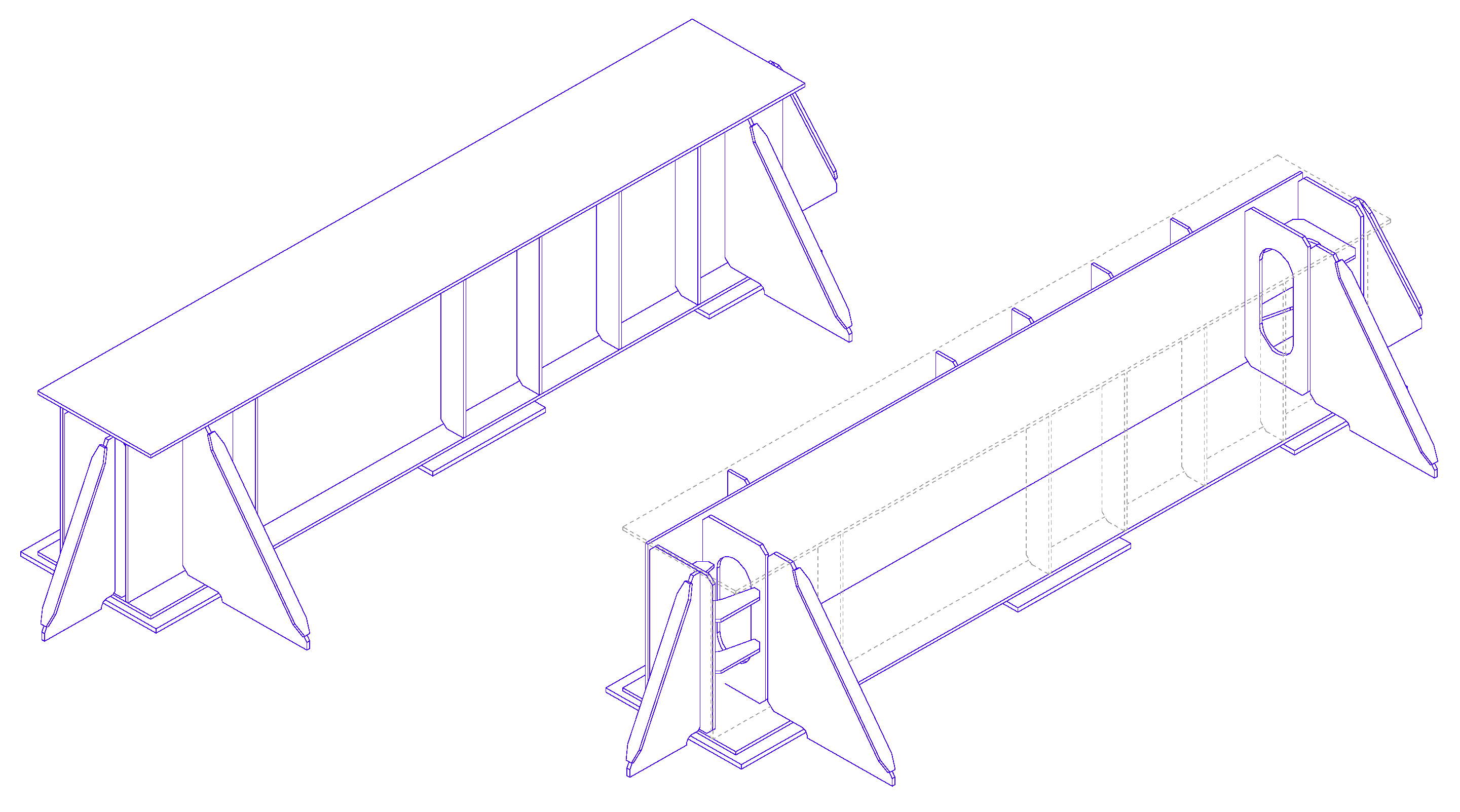
The final design consists of a strengthened beam provided by the following stiffenings in order to counteract the magnitude of the inertia forces:
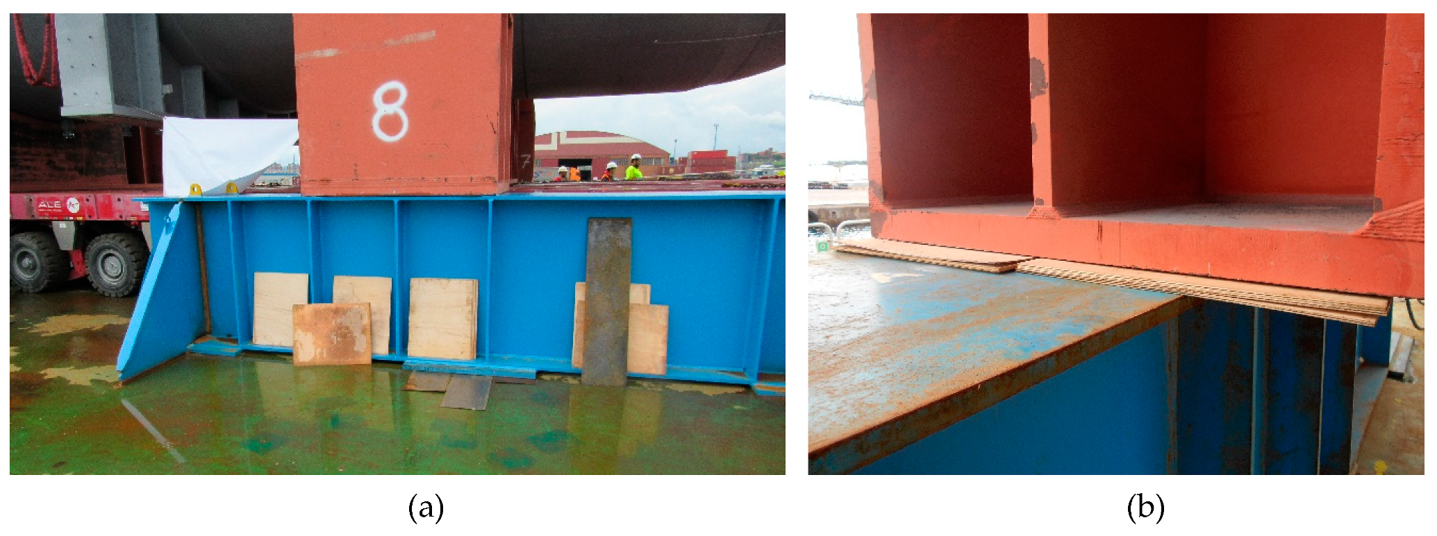
To determine a better distribution of the forces on the vessel deck, the bearing plate installed in the middle of the grillage beam is 32 mm high, unlike the two bearing plates of the ends, which are 35 mm high. Thus, in port conditions when the GSC is placed over the grillage beams, the two extreme bearing plates support and share the static force (gravity). In this situation, the beam suffers some deflection, specifically 1 mm as per calculations carried out with Autodesk Inventor. Once the GSC was stowed over the grillage beam, thin metal plates were placed to shim below the central bearing plate in order to avoid free space between the middle bearing plate and the deck. Although, as per some authors, flat timber or plywood should be placed between the bearing plate and the deck plating, in this case, the limited void space available makes its introduction impossible [
1].
In sea conditions, where the dynamic forces are present, the three bearing plates will support the GSC, and the designed lashing system (welding included) should work as planned.
From a strength point of view, the exact area where the cradle rests over the grillage beam is critical. To overcome this potential problem, the beam is strengthened just below this area with three vertical stiffenings, both installed inside and outside, and along the entire height of the beam.
As the final position of the cradle over the beam may range along its length, the position of these three stiffenings depends on where the ship´s transversal girders are, so they are adjusted in each case as per the final stowage plan. For this reason, three beam designs were considered, where the basic difference was the allocation of the stiffening from one edge (1.577 m; 1.777 m; 1.957 m). In spite of these theoretical positions, as during loading and stowage operations, the final position of the cradle along with the beam could not be exact, and a deviation of up to 50 mm is allowed and does not jeopardize the safety margin, which might correspond to one stiffening not being just below the cradle.
Furthermore, as the areas that suffer most of the shear forces are allocated in the vertical of the inner side of the two ends of the bearing plates, as a reinforcement measure, one more stiffening is installed to each of them lined up with the edges of the bearing plates along the full height. Unlike the previous stiffening, as its position only depends on bearing plates, its location along the beam does not range.
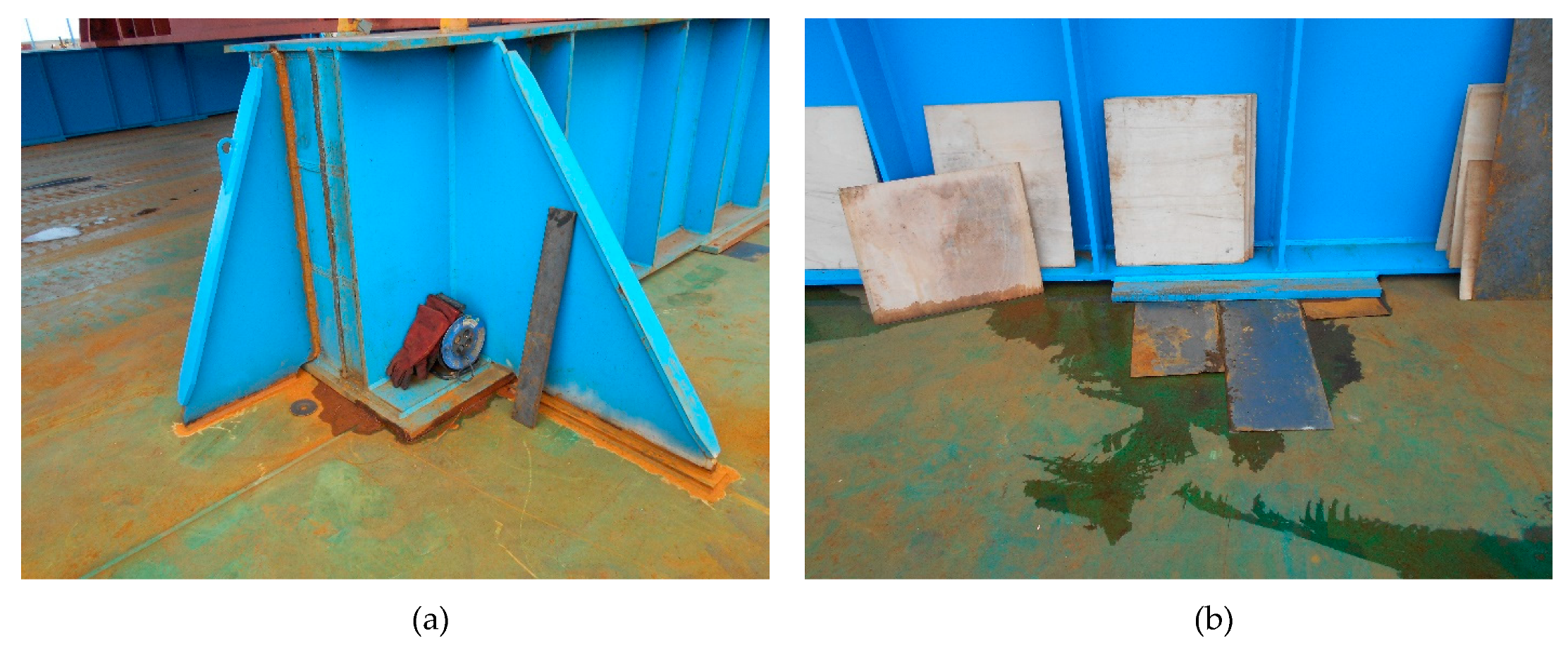
Once the GSC is in stowage position, the SPMT goes down and the footprint cradle rests on the grillage beams, but, as both units are rigid substructures, a void space is inevitable between them. As observed in
Figure 10, in this space, plywood was placed in order to increase the friction and to help prevent sliding [
1].
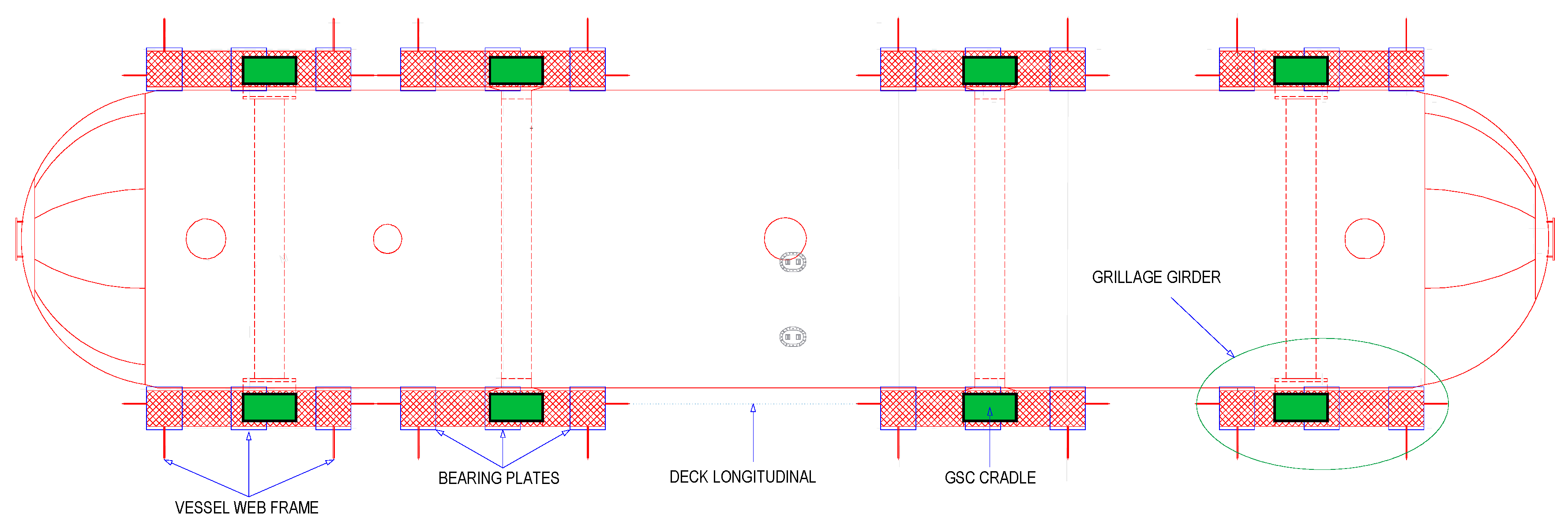
Figure 11 shows the final arrangement of a GSC with its four cradles stowed over the eight grillage beams on the vessel deck.
The exact dimensions of the grillage must be based on the following premises, which consider worst-case scenarios (albeit unlikely) with a sufficient safety margin for any circumstance.
The two bearing plates of the ends only support the beam.
Although the forces are applied along the entire surface of the beam, it is considered that they are exerted upon a single point, located somewhere in the stowage area of the cradle.
Considering the previous premises, the worst-case scenario regarding the bending moment and shear forces is to apply the sum of forces in the middle of the beam [
8].
The vertical force taken into account is 4280.42 kN, the result of the static and dynamic forces sum; however, as has been already mentioned, when dynamic forces are present, the beam is supported by the three bearing plates instead of the two considered in this calculation.
These premises allow for more simplified simulations in the grillage beam, which were carried out with FEM software. This tool provides more accurate results when studying reactions to the deck and stresses suffered by the girder, since all the integrant elements are considered. In all experimental simulations, the designed grillage beam was always working below maximum allowable stress limits (span 5.800 m; load 4280.42 kN).
Table 7 shows the mesh settings of the static analysis carried out in the grillage beams created with the objective of single point contact.
Table 8 includes the stress calculation of the grillage beams, which were designed according to Germanischer Lloyd rules [
21]. As shown in
Table 9, which includes the guidelines, utility checks are always far below the allowable limits.
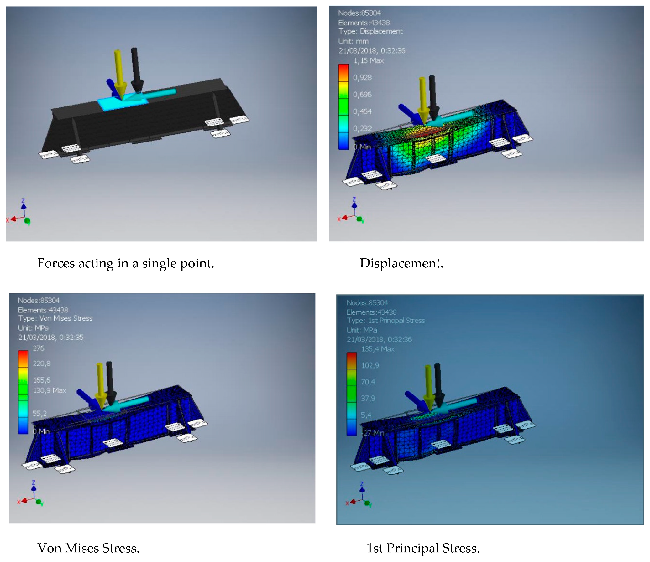
Figure 12 shows some simulation examples among the many carried out with Autodesk. The different arrows represent the different static and dynamic forces.
Four studies were done on each grillage beam:
Static study: Only a static load, supported by two (2) bearing plates and the brackets, was applied, yielding reactions on deck when the GSCs are dropped on the grillage.
Dynamic study: Only dynamic loads, supported by three (3) bearing plates and brackets, were applied, yielding reactions on deck when dynamic forces are applied to the cargo. Combining both reactions, maximum reactions on deck were obtained (static ± dynamics).
Combining Study 2 supports: All forces are applied at the same time (static + dynamics), with two (2) bearing plates as support, yielding maximum bending moments and shear forces on the grillage. Meeting this case demonstrates that the real case is also achieved.
Combining Study 3 supports: All forces are applied at the same time (static + dynamics), with three (3) bearing plates and the brackets as support, yielding maximum compression stresses on the grillage. Meeting this case demonstrates that the real case is also achieved.
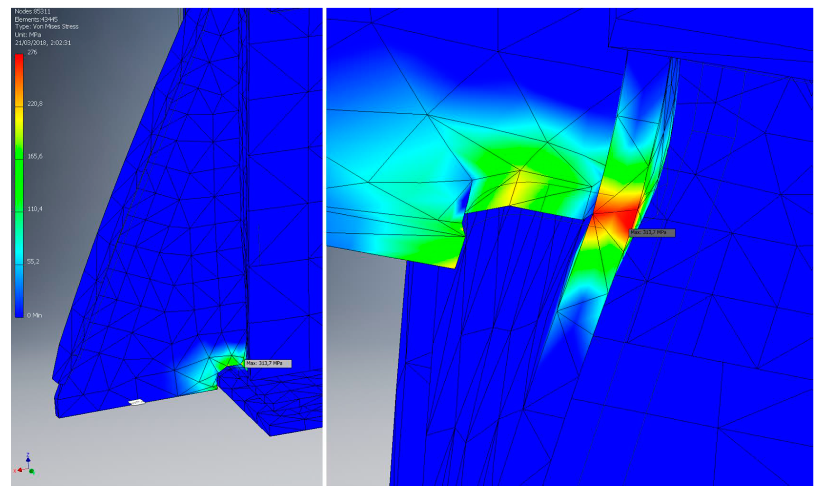
Only by combining cases with two (2) supports, values overcome 276 Mpa, which is the maximum according to Germanischer Lloyd [
21] for Von Mises stresses. However, these stresses are purely local due to longitudinal bracket contact with cover plates and grillage base wings. For this local effect, the guidelines advise one to disregard them if they affect few nodes, which is the case, as can be observed in
Figure 13.
It is observed that this maximum value is clearly due to a local effect. Few nodes are affected, so disregarding it is more than justified.
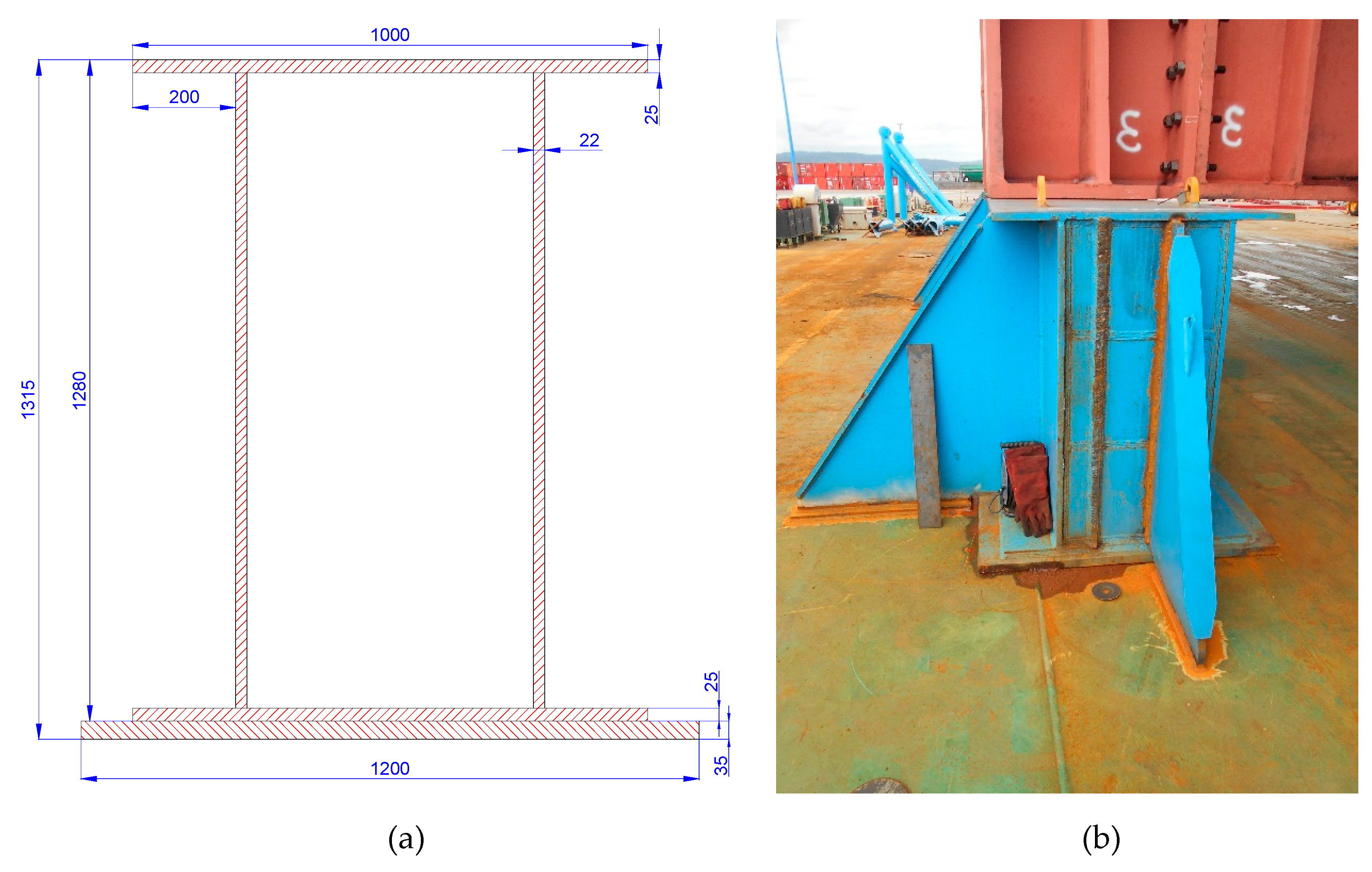
The main dimensions of the grillage beam, following the recommendations established on DNV·GL Rules, are the following:
length (without brackets) 5.800 m (with bearing plates included, 5.900 m)
maximum height 1.315 m (with bearing plates included)
width (without brackets) 1.000 m (with bearing plates included, 1.200 m)
weight 7705 kg
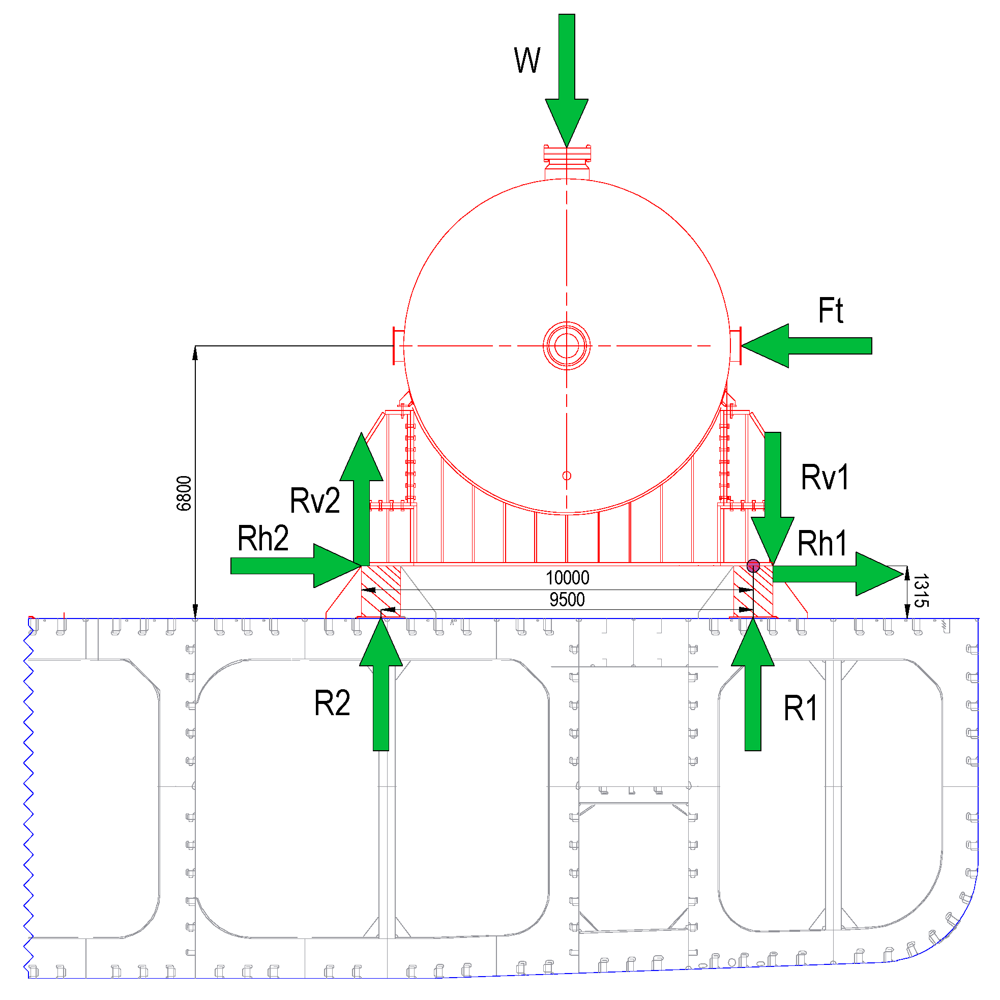
Figure 14 includes more dimensions (in millimeters) of the grillage beam and one placed in stowage position in cross section.
5. Conclusions
Annex 13 of the CSS Code contains a calculation method widely accepted and used in the maritime sector for heavy cargo units. However, in this paper, we showed how, in the maritime sector, in certain ships and cargo units, its premises and securing arrangements are not entirely adequate, so they do not have to be followed literally and in all cases. As the CSS Code cannot provide accurate data of all reasonable accelerations and forces for this particular shipment to assure a high level of safety, an alternative and viable solution, with an equal or higher level of safety, needs to be applied, always considering the Cargo Securing Manual.
The alternative used for the grillage design of the GSCs for the intended voyage on the referred seagoing vessel was the DNV·GL guidelines. These standards and criteria consider empirical design experience and technical developments based on state-of-the-art research and projects. Furthermore, they are mostly internationally accepted and used for the assessment and approval of specialised marine transportations in the project cargo industry, in accordance with the most relevant reputable rules, sharing the common objective of ensuring a safety and feasible sea transport. Therefore, as the characteristics of the designed grillage beam comply with internationally accepted requirements, they can be used with the maximum safety accuracy in this sea voyage and in any other similar project cargo.


