Article

Advanced Monitoring and Prediction of the Thermal State of Intelligent Battery Cells in Electric Vehicles by Physics-Based and Data-Driven Modeling

Technische Hochschule Ingolstadt, Institute of Innovative Mobility, Esplanade 10, 85049 Ingolstadt, Germany
*
Author to whom correspondence should be addressed.
Submission received: 5 March 2021 / Revised: 7 April 2021 / Accepted: 7 May 2021 / Published: 11 May 2021
(This article belongs to the Special Issue Battery Systems and Energy Storage beyond 2020)

Abstract

:
Novel intelligent battery systems are gaining importance with functional hardware on the cell level. Cell-level hardware allows for advanced battery state monitoring and thermal management, but also leads to additional thermal interactions. In this work, an electro-thermal framework for the modeling of these novel intelligent battery cells is provided. Thereby, a lumped thermal model, as well as a novel neural network, are implemented in the framework as thermal submodels. For the first time, a direct comparison of a physics-based and a data-driven thermal battery model is performed in the same framework. The models are compared in terms of temperature estimation with regard to accuracy. Both models are very well suited to represent the thermal behavior in novel intelligent battery cells. In terms of accuracy and computation time, however, the data-driven neural network approach with a Nonlinear AutoregRessive network with eXogeneous input (NARX) shows slight advantages. Finally, novel applications of temperature prediction in battery electric vehicles are presented and the applicability of the models is illustrated. Thereby, the conventional prediction of the state of power is extended by simultaneous temperature prediction. Additionally, temperature forecasting is used for pre-conditioning by advanced cooling system regulation to enable energy efficiency and fast charging.

1. Introduction

In the past few decades, the transport mobility sector, and especially the automotive industry, has experienced considerable changes. In order to address the climate change problems and particularly, to reduce CO 2 emissions, among other technologies, Electric Vehicles (EVs) are becoming increasingly important [1]. Due to their high energy and power density, lithium-ion (li-ion) batteries are the most preferred battery type for EV applications [2]. Nevertheless, the challenges and limitations related to costs, safety and aging need to be addressed and are part of current research [3]. One important factor influencing performance, safety and life time of the battery pack, is temperature [2,4,5]. Low temperatures lead to less available power and capacity and can result in irreversible battery degradation when reaching subzero values. High temperatures outside the optimal range of 15–35 C [4] lead to accelerated aging and may result in a thermal runaway when exceeding the safety limit of 60 C [4,5]. Monitoring battery cell temperatures is, therefore, necessary, which is a task of the Battery Thermal Management System (BTMS) as part of the Battery Management System (BMS) [4]. The basic approach in commercial vehicles is to measure the temperature at a few discrete points at the surface or tab of li-ion cells in the system [6]. In large format battery cells this temperature may greatly differ from the temperature reached in the battery cell core [7,8,9], which is the critical temperature in terms of performance and safety. Therefore, the temperature estimation by using thermal models is a first step and a necessary part to enable precise thermal state monitoring. In addition, predictive thermal management with several advantages, such as the core temperature information, can be utilized [10,11,12,13].
The development of next generation intelligent battery systems takes this into account by advanced monitoring of the individual cell states [14,15]. Sensors are integrated in cell-level electronics and intelligent algorithms determine the cell state, detect faults or perform bad-block management [16,17,18]. In our previous work [19], a prismatic cell was equipped with electronics for single cell data acquisition and system reconfiguration. The use of sensors integrated in mass-produced electronics in combination with thermal models enables the core temperature of the battery cells to be monitored. This avoids the need to integrate additional temperature sensors into the cell, as proposed by [5,7], which would lead to increased production costs and safety issues [8]. However, for thermal state monitoring, the internal cell behavior needs to be modeled and the developed models have to be integrated in the vehicle architecture. Cell-level modeling is necessary, since cooling system gradients and cell-to-cell variations lead to different thermal conditions for cells in a system [20]. A substantial thermal gradient also arises due to the thermal coupling between cells. Therefore, the thermal states of multiple cells differ and need to be monitored individually.
Many different approaches for thermal models for conventional battery cells can be found in the literature. The modeling approaches can generally be separated into physics-based and data-driven models. Another common designation is white-box and black-box modeling depending on the way the results are derived from the inputs. In general, the prediction of a white-box model is physically and geometrically motivated and can be understood more intuitively compared to black-box models which are solely data-driven. There are detailed physical-based electrochemical-thermal models that are coupled, e.g., with geometries modeled by Computational Fluid Dynamics (CFD) or Finite Element Method (FEM) approaches [21,22] or even in combination with mechanical models [23]. Those models are useful for battery design but their main drawback is their low computational speed, which does not allow using them for online temperature estimation in a BTMS [24,25]. Lumped thermal models consider the relevant physical phenomena and simplify the differential equation system by concentrating the important cell characteristics on a few points [24,25]. The model parameters can be derived analytically for known material parameters [24,26,27] or fitted to experimental measurements [25,28]. The latter are a first step towards data-driven models and, therefore, one representative of the so called gray-box approaches. Completely data-driven models do not represent the cell internal physical and geometrical properties and model the output behavior implicitly. Thereby, mostly with the help of machine learning methods mathematical relations between inputs and outputs are trained [29]. Examples are models using Support Vector Machines [30] and Artificial Neural Networks (ANNs) [9,29,31]. The latter are a novel topic of research in the field of thermal battery modeling and have proven to have advantages in modeling non-linear dynamic relations as they can be found in batteries [9]. Nevertheless, the ANN approaches found in the literature are mainly simple network architectures, such as Feedforward (FF) [29,31], and none of them considers integrating the ANN as thermal model in a total model system. Data-driven time-series prediction, implemented, for example, as Nonlinear AutoregRessive with eXogeneous input (NARX) architecture, is particularly reported in the literature to be adequate as thermal parameter forecasting in energy systems [32,33] or surface temperature predictions of cylindrical cells [34]. However, there are currently no models that use NARX networks for core temperature modeling of large format cells, neither for conventional, nor for intelligent batteries.
Since both approaches, physical-based and data-driven modeling, seem to be adequate as thermal battery models, it is important to compare the modeling approaches related to the application in Battery Electric Vehicles (BEVs). Thereby, the latest developments in terms of hardware and structure of intelligent cells are taken into account in this work. Currently, there are neither physical-based nor data-driven models that consider the hardware influences within intelligent cells on the battery’s temperature.
The application of cell individual temperature monitoring by using a thermal model in a real BEV system creates an additional opportunity to estimate the core temperature, and also the new possibility to predict the temperature for future events and to utilize corresponding operation strategies. Only a few approaches exist for using battery temperature prediction in BEV scenarios [10,12,35,36]. The results are promising with thermal models that can be used to improve the prediction of the driving range [35], control the regulation of an air- and liquid-dual cooling system [10], or predict the future available battery power [36]. However, there are certainly more applications in which real-time thermal modeling can lead to advances in the specific prediction scenario. In this work, the cases of State-Of-Power (SOP) prediction and advanced cooling system regulation are proposed.
Prediction functionalities, such as SOP prediction, are important for the BEV application as a means of knowing the available power in situations such as user acceleration requirement or long-term performance availability without fear of overcharging or over-discharging [37]. Current publications focus on the calculation of the available SOP based on current, voltage and State-Of-Charge (SOC) limitations of the cells [37,38,39,40,41,42,43]. For low SOCs, the discharge current is the limiting factor, while for high SOCs, the charging current is taken accordingly. At the same time, the maximum permissible load and the voltage limits of the cell restrict the maximum power output. However, in reality, the SOP is also limited by the rising temperatures during maximum performance. For that purpose, temperature estimation for an adequate SOP prediction is necessary, as performed in this work.
Another investigated use case of temperature prediction is related to the cooling system regulation. Amini et al. [44] argue that temperature prediction achieves a planning horizon to activate or deactivate the cooling system which is necessary as the cooling system contains high thermal masses. By reducing the initial phase for a battery thermal management system, the power necessary for cooling can be reduced in general [45]. Additionally, the goal of the cooling system is always to keep all cells in the optimal thermal range. However, there are applications discussed in the literature that prefer increased temperatures. For example, heating the battery to 40 C instead of cooling it to 25 C is known to reduce the stress and degradation caused by the intercalation and deintercalation processes and, therefore, aging [46]. Another application is the thermally challenging fast charging of EVs. Yang et al. [47,48,49] reveal slow preheating as favorable for fast charging procedures, leading to much less heat generation during the fast charging and, therefore, to less energy demand for the cooling. Collin et al. [50] mention, in their work on advanced fast charging technologies, the first approaches in commercial BEVs that perform defined pre-conditioning to improve fast charging.
In this work, the focus is on developing a thermal model for an intelligent prismatic 25 Ah cell prototype, including electronics for a BEV application. The aim is to represent the thermal interactions within the large format cell and the actual influence of the electronics. For the first time, the existing approaches for conventional battery cells, e.g., a physics-based and a data-driven model using the example of a Thermal Equivalent Circuit Model (TECM) and an ANN respectively, are implemented and compared. The two thermal modeling methods are parametrized and implemented for an existing intelligent cell hardware published in our former work [19] and integrated in a total framework for a BEV application. The models are used for the cell-level temperature estimation of different local temperatures and are compared in terms of parametrization, accuracy and computation time. Using intelligent cells and the thermal models for advanced thermal management, novel temperature prediction applications in a realistic BEV scenario are presented. Improvements for SOP prediction are then presented by considering the thermal cell state. In a second application, an predictive cooling system regulation is presented that enables pre-conditioning for fast charging.

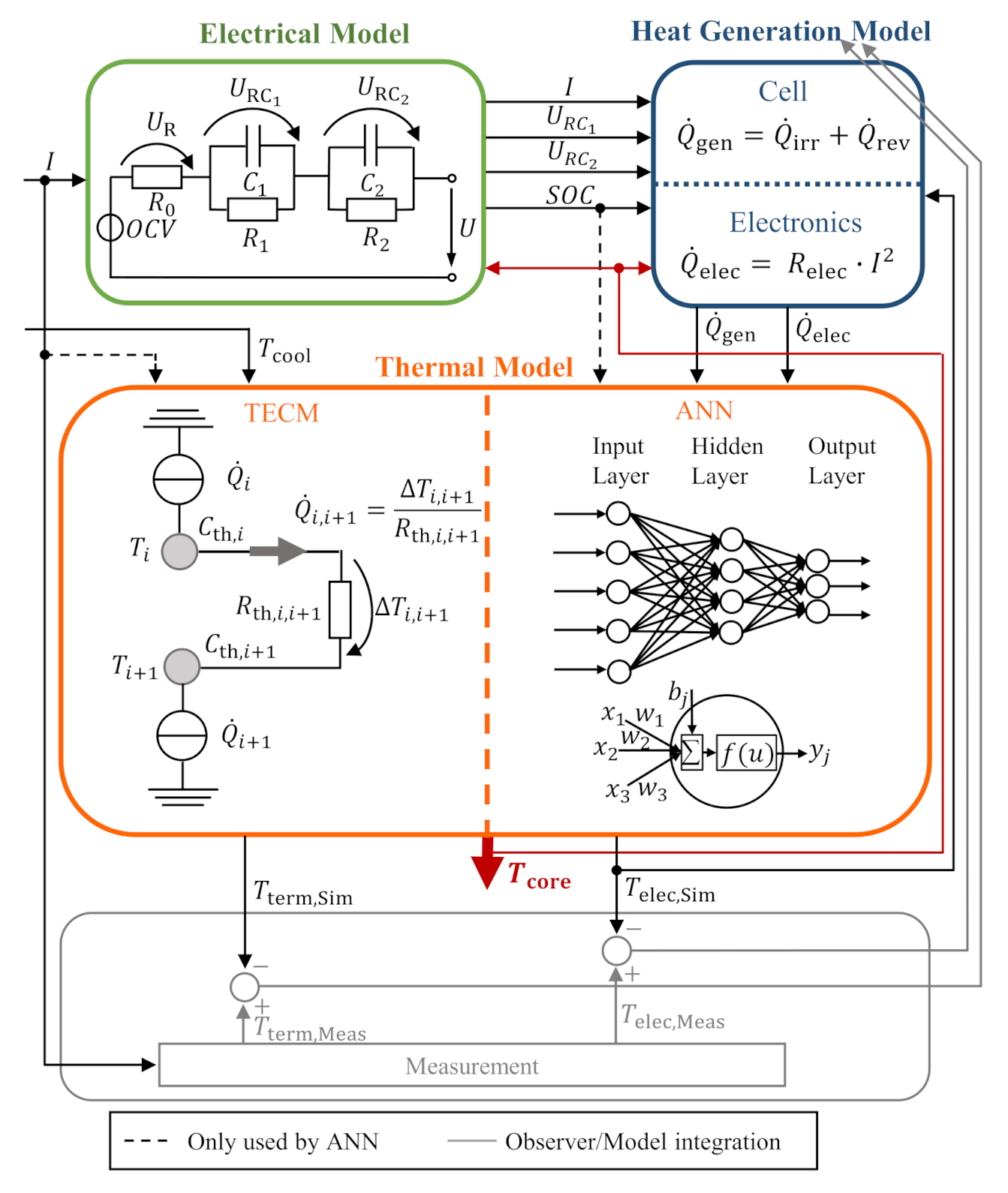
2. General Modeling Approach

The general electro-thermal model framework is shown in Figure 1. It consist of three submodels: an electrical model, a heat generation model and a thermal model. The goal of the total model is to estimate the core temperature of the battery cell. Therefore, a commonly used electro-thermal co-simulation is performed to capture the temperature dependency of several model parameters [21,24,25,27]. The core temperature as and output of the thermal submodel is fed back to the other two submodels, which are described in the following sections. For the integration of the model in BEV applications, an observer is implemented that is described in detail in Section 3.4. The current I, which is determined via measurement in a realistic BEV system, is the input to the total model structure, as well as the observer. For the investigation in this work, two thermal models are implemented and compared that both fit in the same framework. The thermal models are described in detail in Section 3.

2.1. Electrical Model

An Equivalent Circuit Model (ECM) is used as an electrical model, as frequently seen in thermal modeling of battery cells [27,51]. In this work, the model consists of a voltage source, representing the Open Circuit Voltage (OCV) of the cell, a series resistance R 0 corresponding to the cell’s ohmic resistance and two RC-elements, which stand, for the voltage drop due to overvoltages, e.g., charge transfer, diffusion, phase change overvoltages and other losses. The cell terminal voltage U can be calculated from Equation (1) below.
U = O C V + R 0 · I + U RC 1 + U RC 2
All the components of the ECM, e.g., resistances, capacitances and the OCV are dependent on the cell core temperature and the SOC. The temperature is fed back from the thermal submodel and the SOC is calculated inside the electrical submodel using coulomb counting. The resistances and capacitances used for the model parametrization were determined analytically for the 25 Ah cell and published in a previous publication [52].

2.2. Heat Generation Model

The heat generation model comprises two parts. It separately calculates the heat generation in the cell and the electronics components. For the heat generation in the jelly roll, Equation (2) is used based on the simplified energy balance in electrochemical systems by Bernardi et al. [53]:
Q ˙ gen = Q ˙ irr + Q ˙ rev = I 2 · R 0 + U RC 1 2 R 1 + U RC 2 2 R 2 + I · T · d O C V d T
In Equation (2), the first three terms stand for the irreversible heat generation resulting from the voltage drop at the electrical resistances shown in the electrical submodel. It is always positive and therefore, leads to the heating of the cell. The last term in Equation (2) is reversible heat generation, which results from the entropy change during intercalation and the deintercalation of the lithium ions. It may be positive or negative, depending on the SOC and the direction of the current and, therefore, may heat or cool the cell, respectively. The entropy coefficient d O C V / d T is dependent on the temperature and was also determined experimentally in [52].
The second part of the heat generation model calculates the heat generation in the electronics based on joule heating by
Q ˙ elec = i = 1 n I i 2 · R elec , i
R elec , i is the ohmic resistance of the electronics’ pieces, respectively, and is strongly dependent on each components’ temperature. Thereby, n is the number of all different electronics segments. A detailed description of the electronics and the corresponding model is given in Section 3.1 .

3. Thermal Models of an Intelligent Cell

The purpose of the thermal models is to estimate the jelly roll temperature for the given heat input by the heat generation model. In order to compare a physics-based to a data-driven model, a TECM and an ANN are implemented for the example of a prismatic cell prototype for intelligent batteries published in [19]. Thereby, the geometrical as well as boundary conditions for this prototype are defined by the reference system and taken into account for the modeling. Since the focus of this work is on the differences of the two approaches, they are implemented in the same electro-thermal framework to compare accuracy, computational effort and time and applicability to an in-use temperature estimation in a BTMS.

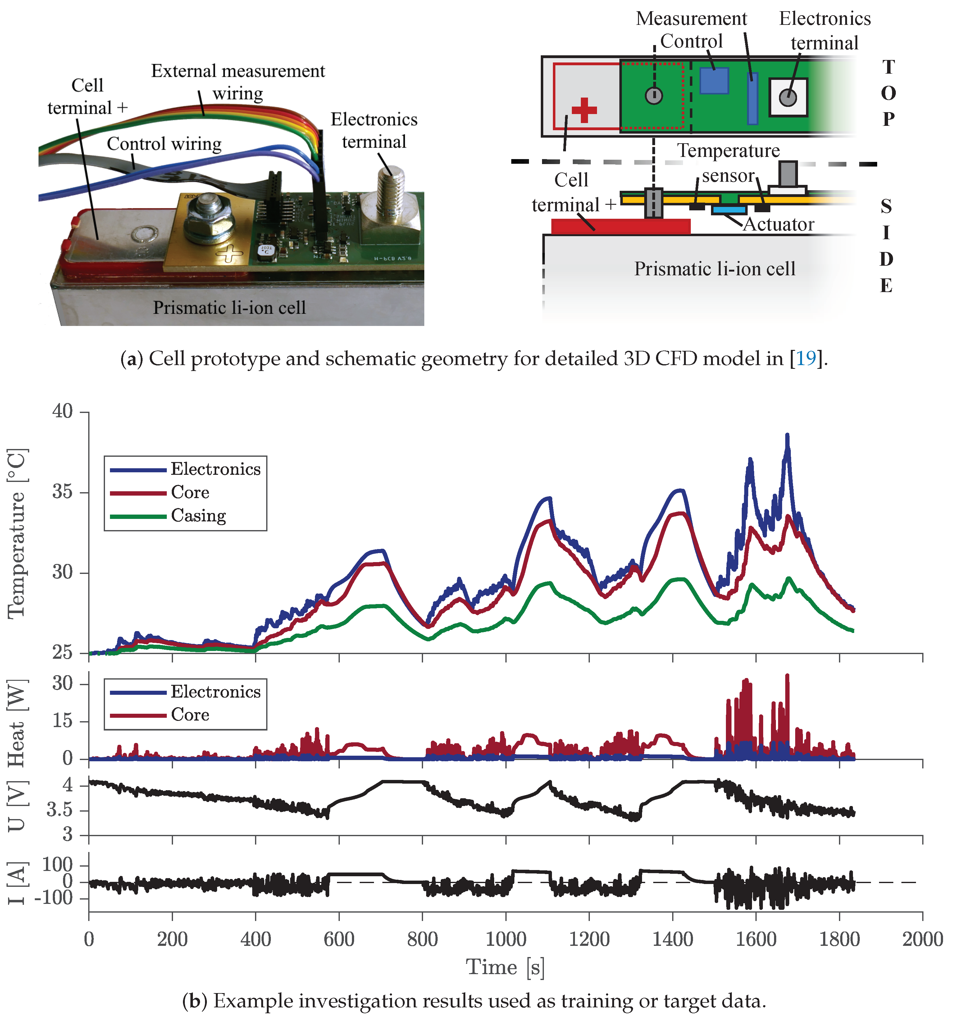
3.1. Reference System

The cell under investigation is a prismatic 25 A h cell from SANYO/Panasonic with a Nickel-Mangan-Cobalt-Oxide (NMC) cathode and graphite anode material. The dimensions of the cell are 14.8   c m , 2.65   c m and 9.1   c m .
In our previous work [19], the cell was combined with electronics to form an intelligent cell prototype. A schematic representation of this setup is shown in Figure 2a. For the prismatic cell equipped with electronics, a detailed electro-thermal 3D CFD model was implemented to investigate the specific influences of the electronics to the cell. The shown cell with electronics is utilized for parametrization of the models of the cell and the electronics in this work. The dataset of the previous investigation is used as target data for both simplified real-time modeling approaches. Considering that no measurement data of the jelly roll core temperature are available, the neural network is trained using the highly resolved and already experimentally validated CFD model. This teacher approach, using a detailed model for the training of a simplified real-time model, is similarly done for other applications, e.g., by Fang et al. [54]. In addition, the neural network uses independent datasets for training and validation. For this purpose, datasets for the temperature range of 15–45 C are available, which contain many different static and dynamic load profiles, as well as the information about local heat generation and temperatures. Figure 2b shows, as an example, a part of the data for a reference temperature of 25 C .
For a meaningful scenario, BEV boundary conditions are considered [21]. The cell is assumed to be adiabatic in all directions with the exception of the connection to the cooling system at the bottom with the temperature T cool . For the investigation on a system level, cells are additionally thermally coupled via the casing and the busbars, which are described in Section 3.4. For a realistic cooling system behavior, a simplified model is introduced that is comparable to [55,56,57]. Thereby, the cooling system is regulated stepwise and rule-based which is an extension of the thermostat controller [58,59]. The maximum heat flow per cell Q ˙ max , that can be dissipated by the cooling system, is controlled in three steps as shown in Figure 3. Starting with a deactivated cooling system for an optimal cell temperature below 30 C in step 0, the cooling system performance rises stepwise to a maximum of 9 W at 38 C for step 3. A hysteresis of 0.3   K , visualized by the marked line, is used for the regulation of the cooling power [60]. Excessive heat production of the cell, exceeding the cooling power limit, leads to an increase in the cooling system temperature.

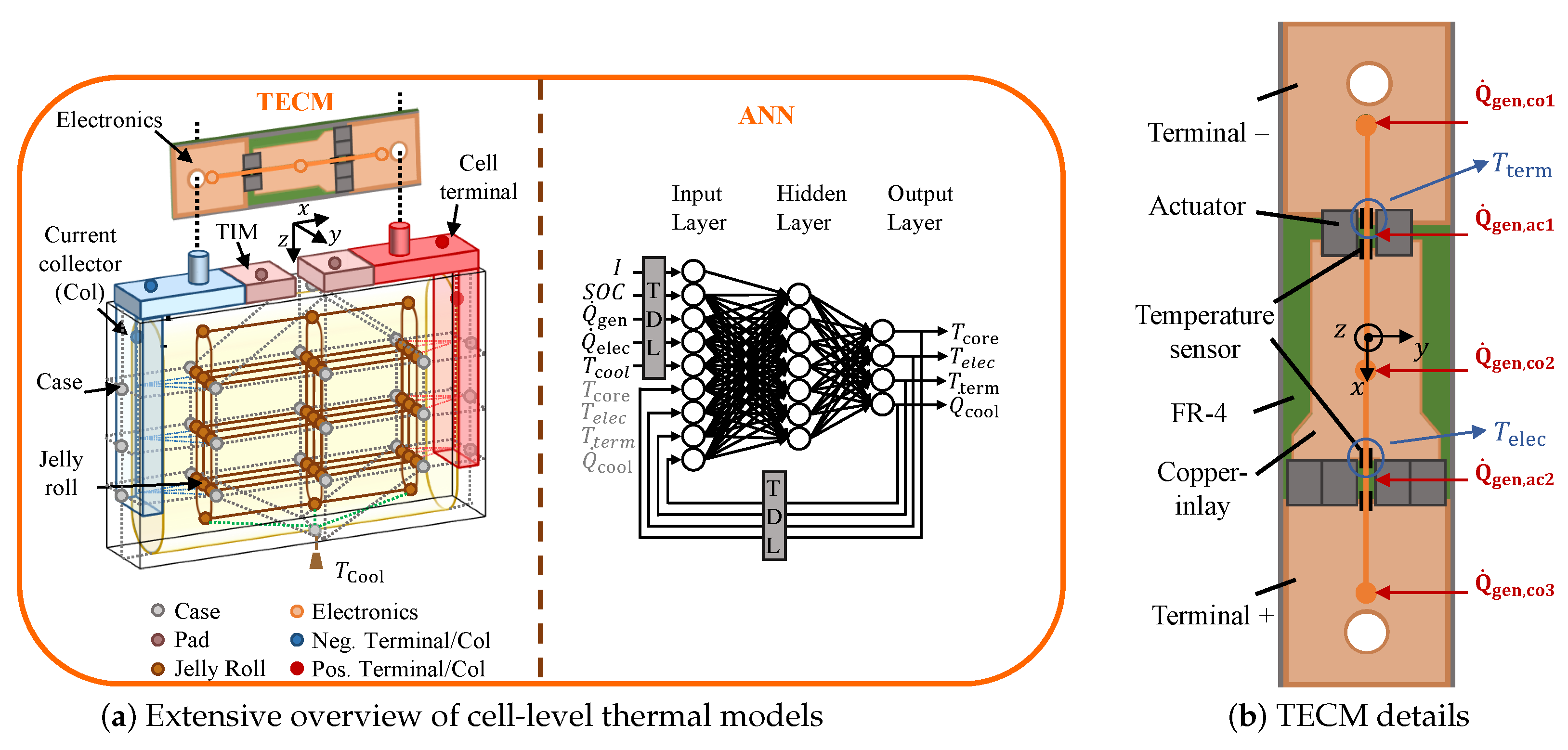
3.2. Physics-Based Thermal Equivalent Circuit Model

A commonly used physics-based modeling approach for conventional cells is a lumped thermal model, also called TECM. The basic structure of TECMs is symbolized in the left-hand section of the thermal submodel in Figure 1. In general, in a TECM, the component to be observed is discretized by small volumes. Each volume is represented by a thermal node, which contains the thermal capacity and parameters of the volume respectively. The thermal capacity of one volume i is calculated using Equation (4).
C th , i = ρ i · V i · c p , i
where ρ i and c p , i are the averaged density and specific heat capacity of the volume i, and V i is its geometric volume. Thermal capacities, therefore, describe the heat accumulation analogously to electrical capacitances [24]. In each thermal node, the volumetric fraction of the total heat generation is used as a heat source, which is analogous to a current source in electrical models. The thermal nodes are connected by thermal resistances defining the heat transfer between them [24]:
R th , cond = L λ · A
L is the distance between two thermal nodes, λ is the heat conduction coefficient of the respective material and A is the cross-sectional area of the heat transfer path between two nodes.
The total TECM for the cell and the detailed electronics model is shown in the left-hand section of Figure 4. Significant temperature gradients can result in large format prismatic battery cells [21]. Therefore, the cell-internal structure is included in the TECM to model a more realistic temperature distribution through a physics-based model in comparison to other implemented lumped thermal models [28]. For that purpose, 3 × 3 × 3 nodes standing for volumes of the same size are arranged in the mid of the jelly roll. In order to model the complex curved geometry of the jelly roll, three nodes are added below and above the 3 × 3 × 3 cuboid, respectively, resulting to a total number of 33 nodes inside the jelly roll. In the same manner, the case is discretized by each of the nine nodes on the x-y-side, three nodes on the y-z-side and two nodes for cell top and one for the bottom. Additional nodes are added for the current collectors and the cell terminals. Computer tomography scans have shown that electrolyte is remaining at the bottom of the case [21]. Therefore, the connection between the jelly roll and the bottom case is considered via heat conduction through the electrolyte.
The electronics can have significant influence on the jelly roll temperature [19]. Therefore, the thermal influences of the specific electronics are considered by a lumped electronics model of the real hardware. In Figure 4a the general positioning and thermal connection of the electronics is revealed. Additionally, Figure 4b depicts a detailed view of the electronics components and the modeling scheme. An one-dimensional heat conduction and temperature distribution along the current path in x-direction is considered. Three thermal nodes are integrated representing the thermal masses of the current conducting copper inlays. Temperature and current dependent heat generation is located in all current carrying parts. The information of the current and the SOC are provided by the framework emulating a BMS, but they are not further used in the present implementation. The TECM calculates the temperature at the thermal nodes and also at the positions where thermistors are integrated on the hardware prototype. Using this presented structure of the TECM makes it possible to estimate the temperature in multiple positions and dimensions of the cell which is advantageous for the later system level implementation described in Section 3.4. The TECM is implemented in MATLAB/Simulink Version 2020a using Simscape.
Thermal masses and thermal resistances are determined analytically on the basis of material parameters, dimensions and manufacturers data of the investigated prismatic cell and electronics. The initial material parameters used are listed in Table 1.

3.3. Data-Driven ANN-Based Thermal Model

In comparison to the physics-based approach, a data-driven model is implemented by means of an ANN shown in the right part of the thermal model in Figure 1 and Figure 4a. ANNs mimic the information processing in human brains by modeling of the nonlinear input-output-relations, which explicitly occur in battery cells [29,62]. Their main advantage is that complex correlations do not have to be physically modeled as networks can be trained to represent the correlations. It is, therefore, necessary to provide the data basis that includes the data correlations to be trained.
Regarding the model architecture and implementation, a network consists of a number of neurons that are arranged in layers. The neurons are connected via edges that contain weights that indicate the strength of the connection. In every neuron, its weighted inputs and a bias are summed, and the sum is mapped, in a nonlinear manner, to the output by the activation function [29,54,62] in Equation (6).
y j = f i n w i · x i + b j
In Equation (6), x i are the inputs to one neuron, w i are the respective edge weights of the inputs, b j is the bias in the neuron, f is the activation function and y j is the neuron’s output. In the training process the weights and biases are updated using known output results. The goal is to minimize the difference between the network output and the target data. The difference is mostly described by the Mean Squared Error (MSE) and is termed the loss function. Several optimizations exist in the literature for minimizing the loss function.
The total ANN thermal model developed in this work is depicted in detail in the right-hand section of Figure 4a. As already mentioned, the implementation of an ANN a dataset containing the input–output correlations to be learned is necessary. The present network is trained based on a dataset generated by the reference system described in Section 3.1. The underlying load profile contains different static (constant charge/discharge) and dynamic load profiles (e.g., the ECE, EUDC, US06, RTS95, FTP72, Artemis Motorway cycles), as well as fast charging and cooling sections without load. In order to simulate varying ambient and cooling conditions, the dataset is generated for different starting temperatures of 15–45 C in steps of 5 C leading to a total of over 273 k timesteps. A dataset provides information of current, SOC, heat generation in cell and electronics, the local temperature of electronics, terminal and core as well as the removed heatflux by cooling for every second. The network inputs are scaled in a range between 0 and 1 using the minimum and maximum values of each feature in the training dataset. This makes the later training more robust and efficient [9,33] and prevents it from putting more emphasis on signals with higher absolute value [45].
The network architecture consists of one input layer, one hidden layer and one output layer. The NARX architecture is implemented for the situation of an cell equipped with electronics. As characteristic of the NARX as recurrent network, the outputs are fed back to the input layer. In contrast to conventional FF networks, this enables the representation of temporal dynamics, which improves the modeling of the thermal cell behavior. Thus, the outputs of different timesteps y ( t 1 ) , y ( t 2 ) …, y ( t d Output ) are stored in a Tapped Delay Line (TDL) and used as inputs for the current timestep y ( t ) . In the same manner, the inputs form different timesteps x ( t ) , x ( t 1 ) , x ( t 2 ) ,…, x ( t d Input ) , which are stored in a TDL and used as inputs to calculate the output y ( t ) at the current timestep. d Input and d Output are the maximum backward timesteps stored in the TDL of the inputs and outputs, respectively [33]. The activation function used for the hidden layer is the Rectified Linear Unit (ReLU) function (Equation (7)):
f ( x ) = R e L U ( x ) = m a x ( 0 , x ) = x if x 0 0 if x < 0
The ReLU function is advantageous because of its lower computing time requirements, compared to other activation functions, such as logsig or tansig [62], which makes it more suitable for the current application in a vehicle BMS.
The main advantage of the NARX approach compared to other data-driven regression networks is the network architecture. A NARX network is implemented with neurons and a structure as simple as a FF network. Therefore, it can be trained with the fast and accurate FF training procedures and algorithms with good convergence. The training algorithm used in this work is the Levenberg-Marquardt (LM) algorithm, which offers a fast convergence for small networks [29]. The network is trained open-loop and independent of the other two submodels, meaning that the loop from the outputs to the inputs is opened by utilizing the known target temperatures. The open-loop configuration allows to efficiently train the NARX net, analogous to FF nets and stable inputs are available [33]. This is the main advantage compared to other recurrent network approaches.
Important features influencing the training time and especially the accuracy of the results are the NARX hyperparameters, such as number of hidden neurons or input delays. In order to determine a suitable architecture for the network, the authors applied the grid-search method [63], meaning that the number of input and output delays and the number of neurons on the hidden layer are varied between 0 to 10, 1 to 10 and 3 to 10 respectively. The span of the parameters was found with prior investigations on testing many parameters on a large scale. For measuring the quality of the current network topology, another independent validation dataset containing different profiles to the training dataset is used. The network with the lowest MSE on the validation set is used as the current best configuration at the initialization by chance. For this application, a net is chosen, which consists of seven neurons on the hidden layer, and TDLs lengths of 7 and 3 for the inputs and outputs respectively. The net and training parameters are summed up in Table 2. In order to avoid extrapolation scenarios, the training profiles are chosen and combined in a way that the physically possible limits of SOC, cell voltage and load are reached. The total dataset generated is split into 70%, 15% and 15% for the training, validation and testing, respectively. In order to avoid overfitting, the early-stopping method is used by means of stopping the training if the MSE on the validation dataset increases in six consecutive epochs [33]. The maximum number of epochs is limited to 150, whereby an epoch is one representation of the total training dataset with adaptation of the weights afterwards [45]. The whole setup and training of the network is performed utilizing the MATLAB Deep Learning Toolbox.

3.4. BEV Integration and System Level Simulation

In order to compare the two modeling approaches, the two thermal submodels are integrated into the presented model framework, including electrical and heat generation submodels. There is a need to avoid drifting of the total model, as the three submodels are strongly intercoupled. An observer is, therefore, included, as shown by the components in gray color in Figure 1. Generally, the observer compares estimated and measured values and the difference is fed back to adopt the estimation [64]. A few approaches can be found in the literature which make use of an observer to estimate the battery cell core temperature by measuring the surface temperature of a battery cell [64,65,66]. In this work, a different observer structure is implemented that compares the temperatures measured and estimated at the electronics T elec and a terminal T term . The difference in the electronics’ temperatures T elec , Sim T elec , Meas is used to update the heat generation at the electronics Q ˙ elec and the difference in the terminal temperatures T term , Sim T term , Meas for adaption of heat generation in the jelly roll Q ˙ gen .
Obviously, there are multiple cells in a battery system that require multiple single cell models. The cells in the system thermally interact with each other [67], and this needs to be considered in system-level modeling. To achieve a fast computing system level simulation, a possible coupling scheme is presented in Figure 5. Temperatures at the boundary of the cell model are used as a boundary condition between the individual cell models connected in series. The coupling can be performed by temperature signal routing instead of full physical coupling to reduce the computational effort. In the system simulation approach, based on single cell models, either the TECM, or the ANN, or another compatible cell-level model, can be used at any time. Possible system representations are that every cell within a module receives data from the case and terminal temperatures of its neighboring cells in order to represent the thermal interactions within a module. The cells at the border of the modules can be assumed to be adiabatic or are also coupled. The modeled boundary conditions depend on the specific application. Overall, the approach is able to represent the thermal coupling or cooling conditions in state-of-the-art battery systems. Nevertheless, system simulation is an ongoing field of research and part of future work.

4. Results and Discussion

4.1. Spatial Temperature Estimation of TECM and ANN

In order to compare the temperature estimation of the real-time thermal models to the target results of the reference system in Section 3.1, an independent dataset of the reference system based on the ADAC electric vehicle cycle is chosen. The corresponding 2000 s current profile is repeated until the lower cut-off voltage of 3 V is reached. For adequate comparison, a homogeneous constant temperature of 25 C is defined for the starting and cooling condition. To emulate realistic application conditions, the target data for the observer contain a normally distributed noise with a mean value of 0 K and a standard deviation of 0.2 K. Figure 6 displays the estimated transient temperatures of the core, the electronics and a terminal, as well as the related temperature deviation Δ T of the real-time models. The need for spatial resolution modeling is clearly illustrated by the differences between the local measurement points. At the point of the maximum temperature, differences of up to 4 K are detected. However, there are differences for the modeling approaches and the positions. At high thermal loads, the TECM slightly overestimates the core temperature and underestimates the terminal temperature. For the temperature estimation at the electronics, the dynamic changes in the electronics heat generation in combination with the three representative thermal masses lead to a maximum deviation of 2.7 K for the TECM. The deviation of the electronics results from the lumped representation. Thereby, thermal masses and resistances are based on the initial geometries and material properties. Thus, parameter deviations and contact resistances lead to differences. Corresponding model deviations can be reduced by simple optimization procedures, which is a step towards data-driven models. Overall, the TECM model reveals a good temperature estimation with the highest mean deviation of 0.15 K at the electronics.
The ANN shows in total very small deviations with a maximum difference of 0.67 K at the electronics temperature. The low noise on the deviation also shows that the dynamics of the specific location is represented accordingly. The advantage of the ANN compared to the TECM is due to the training with comparable datasets, which contain the dynamic behavior. For all locations, the mean deviation is below 0.05 K without any static offset or time-dependent drift of the estimation results. Other comparison differences are summarized in Table 3. The overall estimation accuracy of both models is very good within a RMSE of 0.23 K for the TECM and 0.08 K for the ANN. Regarding the computation of the results, the total solving time with the same commercial laptop is 30 s for the ANN model and 60 s for a maximum timestep of 1 s. Thus, both approaches are adequate for real-time estimation with calculation times of 20 ms and 10 ms per timestep. However, the computation time will differ for realistic BEV hardware, which needs to be the focus of future work.
In general, physics-based or data-driven approaches can be used for estimation and prediction applications, as outlined in the introduction. Both have proven high accuracy for the challenging task of a large format prismatic cell with electronics. Nevertheless, the general concept of the models offers certain advantages and disadvantages for use. The present ANN is more accurate and provides at least small benefits related to the computation time. However, adequate training datasets must exist for training and parametrization. Additionally, changes in the hardware and materials that have not been part of the training data would generate discrepancies in the estimated results. With the physics-based TECM model hardware changes can be implemented easier or the area of application can be extended. The parametrization does not need multiple datasets for different behavior, but a detailed analysis of corresponding geometries and materials. For example, using the model for thermal runaway investigations can be provided by implementing the corresponding Arrhenius-based heat generation equations above the normal temperature range of 60 C , as proposed, e.g., in [68]. Since the lumped approach does not represent all physical phenomena, estimation deviations arise with the present model. However, these can be reduced by suitable optimization processes. The use of both models is discussed in the second part of this paper, which describes the implementation of new BTMS functionalities.

4.2. Prediction Applications

One important task of the BMS is to estimate different battery states [3,8]. A statement about the current state, e.g., the SOP, often requires a prediction of future situations. More information about the present and future behavior can improve the state prediction and regulation procedures. In the current work, precise thermal models are available and, based on their temperature prediction capability novel BTMS, functionalities are developed. Thereby, an optimization of existing SOP prediction approaches is demonstrated by taking into account the thermal cell state. On the other hand, a novel battery pre-conditioning approach for fast charging optimization is presented.

4.2.1. Improvement of the SOP Prediction

Present SOP prediction strategies are based primarily on current, voltage, and SOC limits [37,40]. The thermal battery state is largely neglected [69]. Taking the example of a common scenario of highway driving followed by fast charging, the importance of taking the temperature into account is presented. Figure 7 depicts the current profile and the related temperature increase in the target data of the reference system. While driving, both thermal models are used to estimate the core temperature of a cell. Both models conform very well to the target data with a small deviation of less than 0.1 K for the ANN and a maximum of 0.8 K for the TECM. The maximum deviation appears in both cases during fast charging at the highest thermal stress of the cell. Subsequently, a conventional power prediction is performed without the observer for the upcoming continuation of the driving and the expected thermal behavior is predicted for different permissible current scenarios. A detailed view of the mid-term prediction scenario is displayed on the right side of Figure 7. As revealed by the results of both models, the only electrical-based conventional calculation of the SOP will exceed the safety temperature limit of 60 C . In addition, predicting the point in time for reaching the voltage or SOC limit is not performed correctly without taking into account the temperature dependency of the corresponding electrical parameters. Bearing in mind the temperature limit, one may reduce the total permissible output current so that the maximum allowable temperature is not reached during the total discharging (see dashed lines in both cases). This, in turn, restricts the available power in the early stage.
An optimized SOP prediction by an individual output current limitation based on temperature prediction is, therefore, desirable. Multiple output current scenarios can be calculated in advance and the resulting temperature is predicted, which enables maximized performance, while staying within the battery safety limits. Both modeling approaches reveal comparable predicted temperature results. The differences arise from the model’s specific absolute temperature predictions.
On the basis of the detailed models, multiple different reference temperatures can be combined with adaptive and intelligent algorithms for safe prediction optimization. Nevertheless, concrete algorithms are beyond the scope of this work and form part of future investigations. In the present investigation, a simple optimization of the point in time for limiting the output current and the current value after limitation is performed (Figure 7). Once a thermally safe scenario has been found, the associated current profile can be used to calculate the available power. Thus, the investigation clearly shows that considering the temperature development is necessary for an accurate, safe and maximized performance SOP prediction.

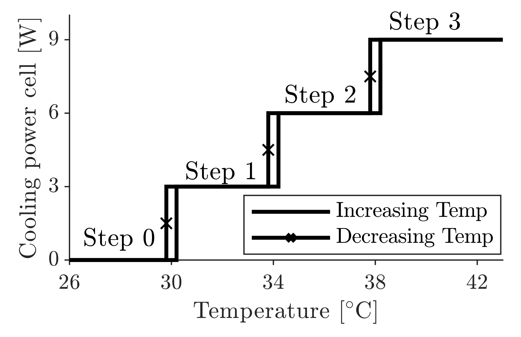
4.2.2. Predictive Thermal Management

In addition to advanced state monitoring and prediction, detailed thermal models also enable the specific control of the cooling system. Conventional cooling system approaches for BEVs normally react to measured temperatures, e.g., at the cell terminals, and do not act predictively to achieve target temperatures. There are already approaches in the literature for novel BTMS that use model-based temperature prediction in order to react to varying conditions [10,11]. At this point, we add another approach to the existing ones, which relates to the thermal pre-conditioning of batteries. In their work, Collin et al. [50] propose to elevate the battery system temperature in order to enable an optimized fast charging. To meet this goal, the future cooling regulation does not only depend on static temperature rules but also needs to be adjusted.
For the same BEV driving scenario as for the SOP prediction, the step-wise cooling system behavior (see Figure 3) and the resulting terminal temperature are shown in Figure 8. The current profile, the related temperature increase and the cooling system behavior of the target data are depicted in black until the end of fast charging at 3200 s.
The models show comparable estimation behavior with good representation of the transient temperature development. In both cases, the largest deviation arises at the beginning of fast charging. The terminal temperature is underestimated for the initial fast charging section with a maximum deviation of 0.7 K for the TECM and 0.5 K for the NARX. Afterwards, the NARX converges to the target temperature more quickly, while the TECM requires the period towards the end of charging. The increased deviation for the terminal temperature estimation compared to the core temperature estimation in Figure 7 corresponds with the findings from the validation. Subsequent to the fast charging, the models are used to predict the temperature for the basic cooling system behavior of Figure 3 for continued highway driving after fast charging stops.
Here, it should be mentioned that a key aspect of thermal prediction is load prediction. However, the prediction of the future current is a stand-alone field of current research and, for example, performed based on navigation profiles and geographical data [70]. In this work, we assume that the future vehicle velocity profile on a motorway contains comparable elements in the same order of magnitude as the previous highway driving. Based on this velocity profile and a simplified vehicle model, a load profile is calculated. In a real BEV application, this simple prediction can be optimized, e.g., by navigation information or driver behavior models.
It can be seen in the case of both models, that the present terminal temperatures lead to the activation of the cooling system and a transient temperature decrease towards 30 C . However, if the destination is the next fast charging stop, raising the temperature towards the end could be more suitable [48]. Using the thermal models, in a simple optimization procedure, temperature development during dynamic driving towards the next charging stop can be predicted while testing different pre-conditioning timelines. The resulting differences in the transient temperature development of the core temperature are visualized in gray color. Using the simple battery cooling model in combination with model-based temperature prediction, the resulting temperature at the next charging station can be increased. In such a case, the range of the variation depends on concrete application, including the thermal mass of the battery, the ambient temperature and the distance to the next charging stop. It is shown that, depending on the respective cooling step and the switching time, the resulting cell temperature can be varied. Using thermal models for predictive thermal management in applications of this type has several advantages. The favored target temperatures can be reached precisely. In addition, unnecessary cooling power to temporarily reduce the cell temperature is available as electrical energy [44] and, therefore, extends, e.g., the vehicle’s range. Furthermore, the thermal conditions for fast charging procedures can be optimized to improve the performance and extend the lifetime [50].
A possible enhanced BTMS needs to evaluate and weight the different influencing factors, e.g., battery temperature, future driving state and effect on driving range, to choose an optimal strategy for cooling system power regulation. In contrast to the already described approaches in the introduction, monitoring the cells’ individual temperatures also enables a new degree of freedom for reacting to maximum temperatures inside the battery system and specific cooling regulation.

5. Conclusions

In this work, a physics-based TECM and a data-driven ANN model have been implemented as thermal models for a prismatic li-ion cell equipped with electronics for the application of intelligent battery systems. For the TECM, a lumped thermal model of the cell has been combined with a lumped electronics model. The novel ANN approach with a NARX network is implemented with the same model interfaces as the TECM to fit into an electro-thermal model framework for a BEV application. Both models are parametrized/trained with datasets based on a reference hardware setup of our previous work [19]. Subsequently, the model behavior is validated and several applications of temperature estimation and prediction are investigated. The following conclusions can be made:
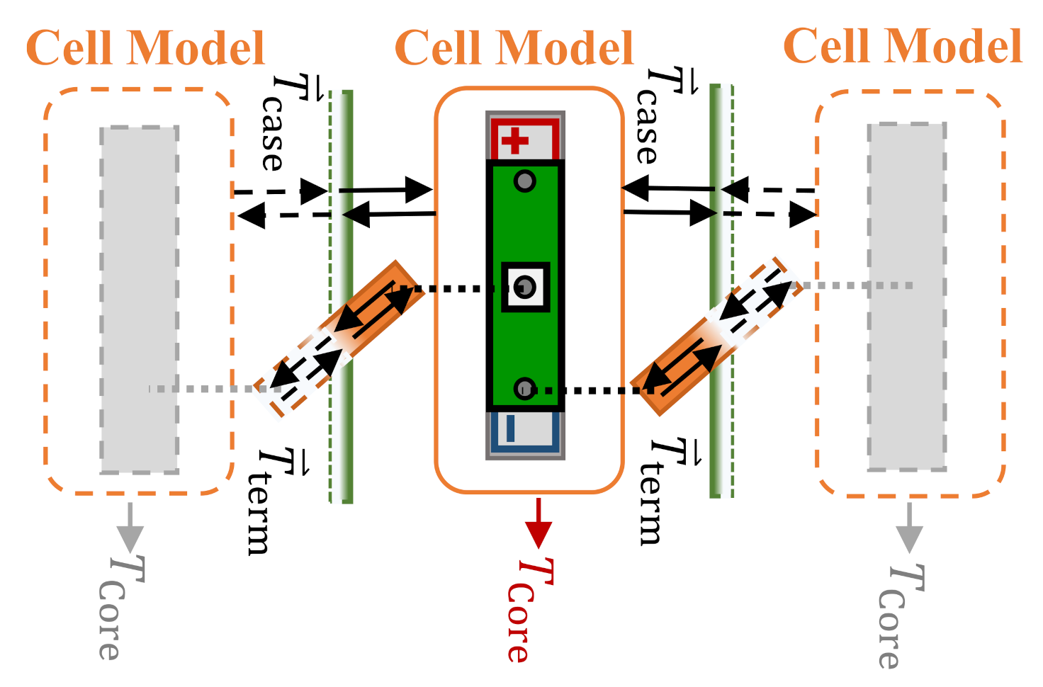
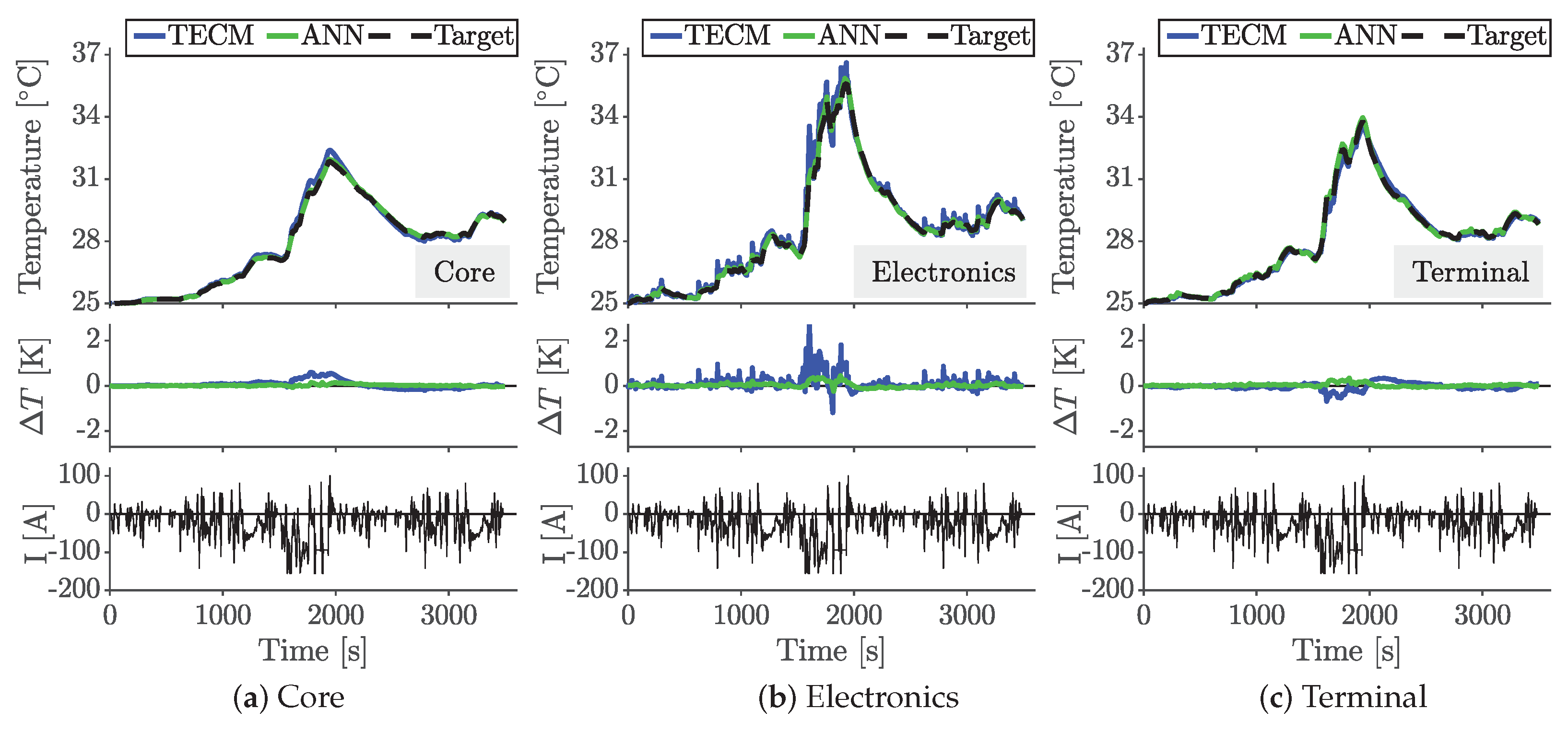
  • The temperature estimation of both modeling approaches is in good accordance with the reference temperatures for multiple locations. Thereby, the RMSE is 0.23 K for the TECM and only 0.08 K for the ANN for a dynamic BEV driving cycle. Thus, for the first time, thermal models are presented, that are able to represent the thermal interactions in novel cell assemblies for intelligent batteries. The detected cell internal temperature differences of 4 K confirm the need of cell level thermal modeling.
  • Comparing physical-based and data-driven modeling, the advantages of the data-driven ANN lie in its high accuracy and fast computation time. The TECM offers advantages in parametrization and the flexibility of the configuration, since it does not need to be trained with target data. Since both models reveal adequate estimation results, the selection depends on the application of intelligent batteries.
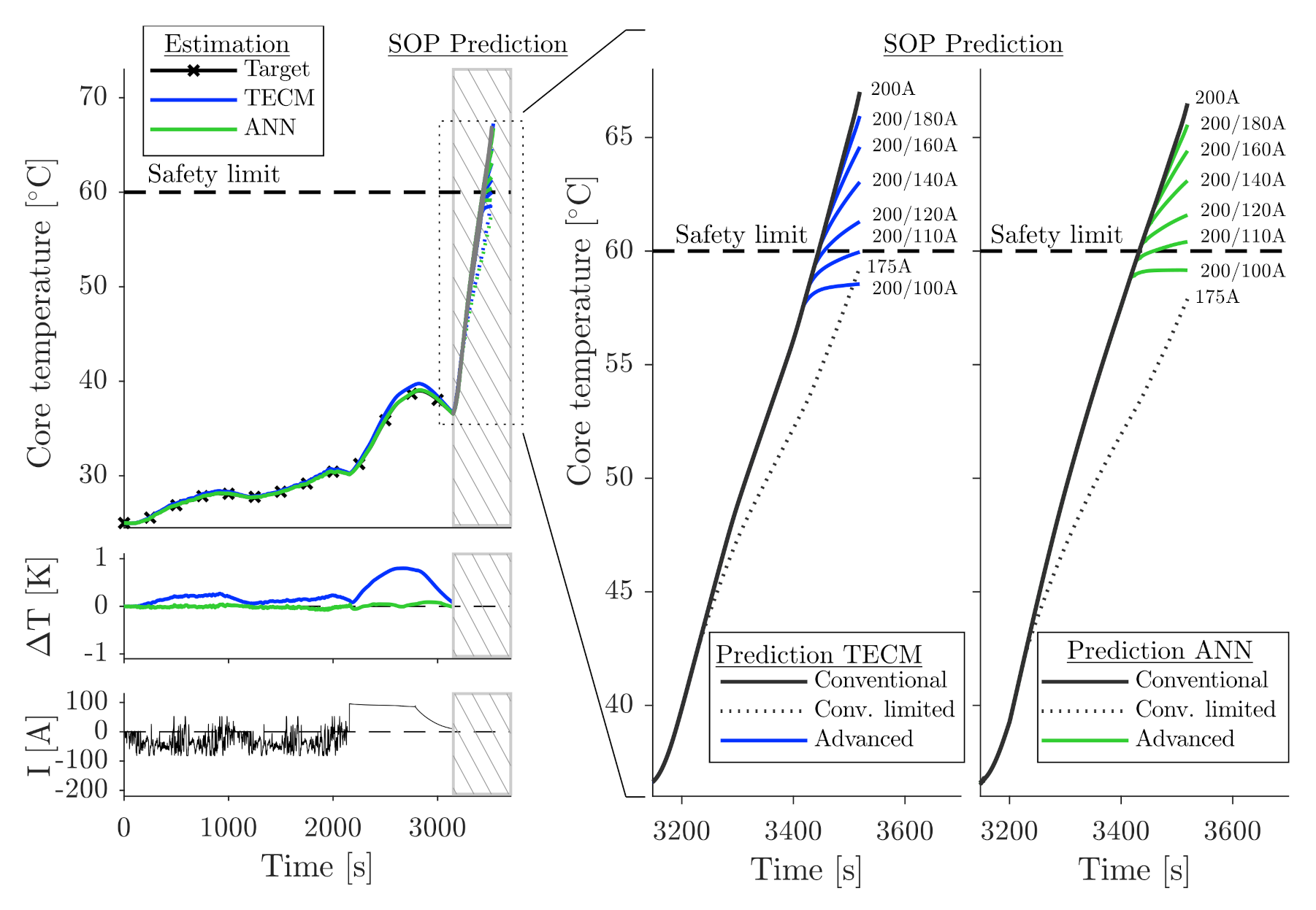
  • In addition to thermal state estimation, thermal models in combination with the present model framework enable prediction functionalities for a BTMS. The information base for SOP prediction can be enlarged through the consideration of the thermal state. As a result, the thermal safety limits are respected and the available short-term power is maximized.
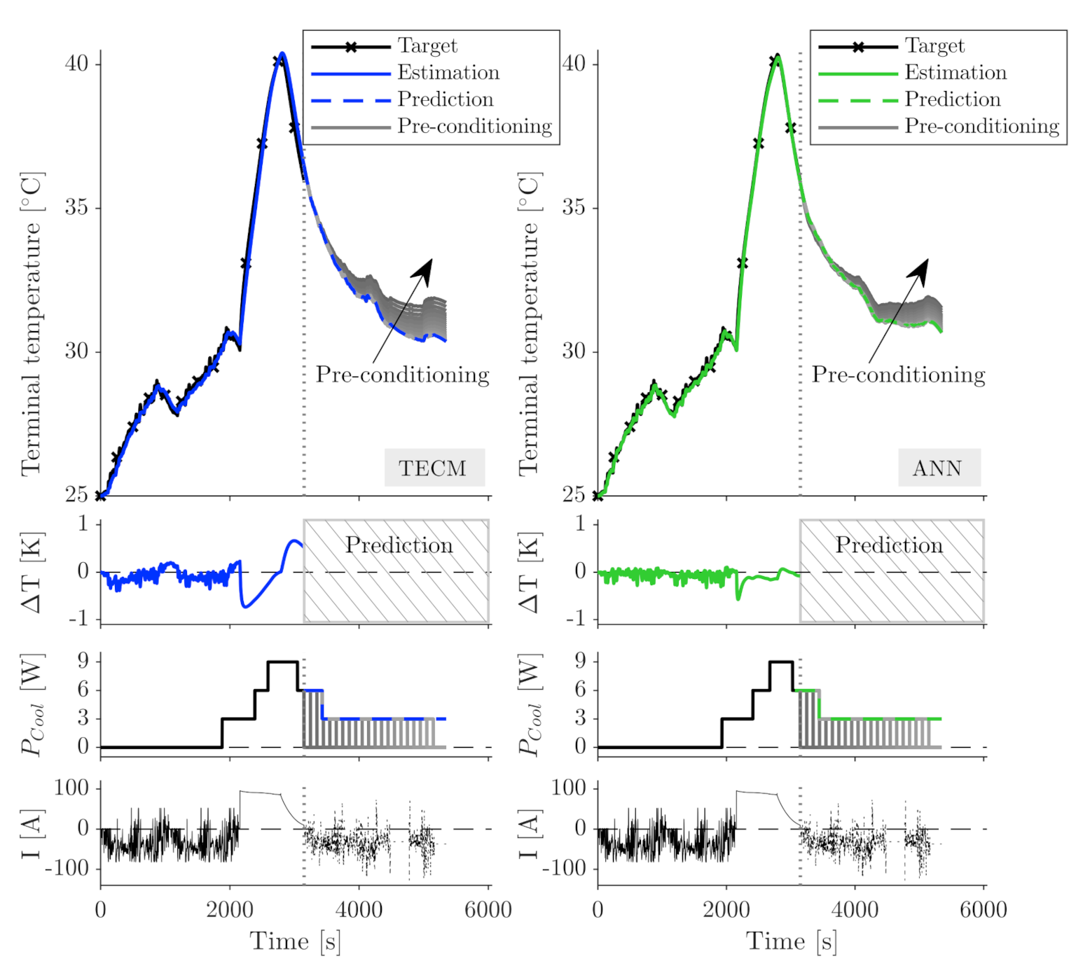
  • In a second prediction application, predictive cooling system regulation is presented. Thereby, pre-conditioning for special BEV applications, e.g., fast charging, for maximizing the BEV energy efficiency and aging conditions is possible.
The focus of future work is on the development and optimization of the corresponding algorithms for SOP prediction and advanced thermal management functionalities and related verification on an intelligent battery system hardware.

Author Contributions

Conceptualization, J.K., M.S. and L.K.; methodology, J.K.; software, J.K. and M.S.; validation, J.K. and M.S.; investigation, J.K., M.S. and L.K.; writing—original draft preparation, J.K. and M.S.; writing—review and editing, J.K., M.S. and L.K.; visualization, J.K.; supervision, L.K. and C.E.; project administration, C.E. All authors have read and agreed to the published version of the manuscript.

Funding

This research received no external funding.

Acknowledgments

The authors would like to express their appreciation to Michael Hinterberger (AUDI AG, Ingolstadt) for the valuable expert advice and acknowledge F. Haselbeck and L. Lechermann for the extensive discussions related to the implementation and training of learning systems. This work was supported by the AUDI AG, Ingolstadt, Germany.

Conflicts of Interest

The authors declare no conflict of interest.

Abbreviations

The following abbreviations are used in this manuscript:
ANNArtificial Neural Network
BEVBattery Electric Vehicle
BMSBattery Management System
BTMSBattery Thermal Management System
CFDComputational Fluid Dynamics
EVElectric Vehicle
ECMEquivalent Circuit Model
FFFeedforward
FEMFinite Element Method
li-ionlithium-ion
LMLevenberg-Marquardt
MSEMean Squared Error
NARXNonlinear AutoregRessive with eXogeneous input
NMCNickel-Mangan-Cobalt-Oxide
OCVOpen Circuit Voltage
ReLURectified Linear Unit
SOCState-Of-Charge
SOPState-Of-Power
TDLTapped Delay Line
TECMThermal Equivalent Circuit Model

References

  1. Canals Casals, L.; Martinez-Laserna, E.; Amante García, B.; Nieto, N. Sustainability analysis of the electric vehicle use in Europe for CO2 emissions reduction. J. Clean. Prod. 2016, 127, 425–437. [Google Scholar] [CrossRef]
  2. Karimi, G.; Li, X. Thermal management of lithium-ion batteries for electric vehicles. Int. J. Energy Res. 2013, 37, 13–24. [Google Scholar] [CrossRef]
  3. Lu, L.; Han, X.; Li, J.; Hua, J.; Ouyang, M. A review on the key issues for lithium-ion battery management in electric vehicles. J. Power Sources 2013, 226, 272–288. [Google Scholar] [CrossRef]
  4. Xia, G.; Cao, L.; Bi, G. A review on battery thermal management in electric vehicle application. J. Power Sources 2017, 367, 90–105. [Google Scholar] [CrossRef]
  5. Zhang, G.; Cao, L.; Ge, S.; Wang, C.Y.; Shaffer, C.E.; Rahn, C.D. In Situ Measurement of Radial Temperature Distributions in Cylindrical Li-Ion Cells. J. Electrochem. Soc. 2014, 161, A1499–A1507. [Google Scholar] [CrossRef] [Green Version]
  6. Wang, Y.; Chen, Z.; Zhang, C. On-line remaining energy prediction: A case study in embedded battery management system. Appl. Energy 2017, 194, 688–695. [Google Scholar] [CrossRef]
  7. Lee, C.Y.; Lee, S.J.; Hung, Y.M.; Hsieh, C.T.; Chang, Y.M.; Huang, Y.T.; Lin, J.T. Integrated microsensor for real-time microscopic monitoring of local temperature, voltage and current inside lithium ion battery. Sens. Actuators A Phys. 2017, 253, 59–68. [Google Scholar] [CrossRef]
  8. Wang, Y.; Tian, J.; Sun, Z.; Wang, L.; Xu, R.; Li, M.; Chen, Z. A comprehensive review of battery modeling and state estimation approaches for advanced battery management systems. Renew. Sustain. Energy Rev. 2020, 131, 110015. [Google Scholar] [CrossRef]
  9. Liu, K.; Li, K.; Peng, Q.; Guo, Y.; Zhang, L. Data-Driven Hybrid Internal Temperature Estimation Approach for Battery Thermal Management. Complexity 2018, 2018, 1–15. [Google Scholar] [CrossRef] [Green Version]
  10. Zhu, C.; Lu, F.; Zhang, H.; Mi, C.C. Robust Predictive Battery Thermal Management Strategy for Connected and Automated Hybrid Electric Vehicles Based on Thermoelectric Parameter Uncertainty. IEEE J. Emerg. Sel. Top. Power Electron. 2018, 6, 1796–1805. [Google Scholar] [CrossRef]
  11. Zhu, C.; Lu, F.; Zhang, H.; Sun, J.; Mi, C.C. A Real-Time Battery Thermal Management Strategy for Connected and Automated Hybrid Electric Vehicles (CAHEVs) Based on Iterative Dynamic Programming. IEEE Trans. Veh. Technol. 2018, 67, 8077–8084. [Google Scholar] [CrossRef]
  12. Wan, J.; Wu, C. The Effects of Driver Speed Prediction-Based Battery Management System on Li-ion Battery Performance for Electric Vehicles. Proc. Hum. Factors Ergon. Soc. Annu. Meet. 2014, 58, 515–519. [Google Scholar] [CrossRef]
  13. Kim, E.; Shin, K.G.; Lee, J. Real-time battery thermal management for electric vehicles. In Proceedings of the 2014 ACM/IEEE International Conference on Cyber-Physical Systems (ICCPS), Berlin, Germany, 14–17 April 2014; IEEE: Piscataway, NJ, USA, 2014; pp. 72–83. [Google Scholar] [CrossRef]
  14. Steinhorst, S.; Lukasiewycz, M.; Narayanaswamy, S.; Kauer, M.; Chakraborty, S. Smart Cells for Embedded Battery Management. In Proceedings of the Cyber-Physical Systems, Networks and Applications (CPSNA), Hong Kong, China, 25–26 August 2014; IEEE: Piscataway, NJ, USA, 2014; pp. 59–64. [Google Scholar] [CrossRef]
  15. Otto, A.; Rzepka, S.; Mager, T.; Michel, B.; Lanciotti, C.; Günther, T.; Kanoun, O. Battery Management Network for Fully Electrical Vehicles Featuring Smart Systems at Cell and Pack Level. In Advanced Microsystems for Automotive Applications 2012; Meyer, G., Ed.; Springer: Berlin/Heidelberg, Germany, 2012; pp. 3–14. [Google Scholar]
  16. Schneider, D.; Vögele, U.; Endisch, C. Model-based sensor data fusion of quasi-redundant voltage and current measurements in a lithium-ion battery module. J. Power Sources 2019, 440, 227156. [Google Scholar] [CrossRef]
  17. Schmid, M.; Kneidinger, H.; Endisch, C. Data-Driven Fault Diagnosis in Battery Systems through Cross-Cell Monitoring. IEEE Sens. J. 2020, 1. [Google Scholar] [CrossRef]
  18. Schmid, M.; Gebauer, E.; Hanzl, C.; Endisch, C. Active Model-Based Fault Diagnosis in Reconfigurable Battery Systems. IEEE Trans. Power Electron. 2021, 36, 2584–2597. [Google Scholar] [CrossRef]
  19. Kleiner, J.; Heider, A.; Hanzl, C.; Komsiyska, L.; Elger, G.; Endisch, C. Thermal Behavior of an Intelligent Li-Ion Cell under Vehicle Conditions. In Proceedings of the IECON 2020 The 46th Annual Conference of the IEEE Industrial Electronics Society, Singapore, 18–21 October 2020; pp. 2081–2086. [Google Scholar] [CrossRef]
  20. Feng, F.; Hu, X.; Hu, L.; Hu, F.; Li, Y.; Zhang, L. Propagation mechanisms and diagnosis of parameter inconsistency within Li-Ion battery packs. Renew. Sustain. Energy Rev. 2019, 112, 102–113. [Google Scholar] [CrossRef]
  21. Kleiner, J.; Komsiyska, L.; Elger, G.; Endisch, C. Thermal Modelling of a Prismatic Lithium-Ion Cell in a Battery Electric Vehicle Environment: Influences of the Experimental Validation Setup. Energies 2020, 13, 62. [Google Scholar] [CrossRef] [Green Version]
  22. Lundgren, H.; Svens, P.; Ekström, H.; Tengstedt, C.; Lindström, J.; Behm, M.; Lindbergh, G. Thermal Management of Large-Format Prismatic Lithium-Ion Battery in PHEV Application. J. Electrochem. Soc. 2016, 163, A309–A317. [Google Scholar] [CrossRef]
  23. Rieger, B.; Erhard, S.V.; Kosch, S.; Venator, M.; Rheinfeld, A.; Jossen, A. Multi-Dimensional Modeling of the Influence of Cell Design on Temperature, Displacement and Stress Inhomogeneity in Large-Format Lithium-Ion Cells. J. Electrochem. Soc. 2016, 163, A3099–A3110. [Google Scholar] [CrossRef]
  24. Damay, N.; Forgez, C.; Bichat, M.P.; Friedrich, G. Thermal modeling of large prismatic LiFePO4/graphite battery. Coupled thermal and heat generation models for characterization and simulation. J. Power Sources 2015, 283, 37–45. [Google Scholar] [CrossRef]
  25. Farag, M.; Sweity, H.; Fleckenstein, M.; Habibi, S. Combined electrochemical, heat generation, and thermal model for large prismatic lithium-ion batteries in real-time applications. J. Power Sources 2017, 360, 618–633. [Google Scholar] [CrossRef]
  26. Zhao, Y.; Patel, Y.; Zhang, T.; Offer, G.J. Modeling the Effects of Thermal Gradients Induced by Tab and Surface Cooling on Lithium Ion Cell Performance. J. Electrochem. Soc. 2018, 165, A3169–A3178. [Google Scholar] [CrossRef]
  27. Stocker, R.; Lophitis, N.; Mumtaz, A. Development and Verification of a Distributed Electro-Thermal Li-Ion Cell Model. In Proceedings of the IECON 2018-44th Annual Conference of the IEEE Industrial Electronics Society, Washington, DC, USA, 21–23 October 2018. [Google Scholar]
  28. Li, D.; Yang, L. Identification of spatial temperature gradient in large format lithium battery using a multilayer thermal model. Int. J. Energy Res. 2020, 44, 282–297. [Google Scholar] [CrossRef]
  29. Fang, K.; Mu, D.; Chen, S.; Wu, B.; Wu, F. A prediction model based on artificial neural network for surface temperature simulation of nickel–metal hydride battery during charging. J. Power Sources 2012, 208, 378–382. [Google Scholar] [CrossRef]
  30. Chen, Z.; Xiong, R.; Lu, J.; Li, X. Temperature rise prediction of lithium-ion battery suffering external short circuit for all-climate electric vehicles application. Appl. Energy 2018, 213, 375–383. [Google Scholar] [CrossRef]
  31. Panchal, S.; Dincer, I.; Agelin-Chaab, M.; Fraser, R.; Fowler, M. Experimental and theoretical investigation of temperature distributions in a prismatic lithium-ion battery. Int. J. Therm. Sci. 2016, 99, 204–212. [Google Scholar] [CrossRef]
  32. Kim, J.H.; Seong, G.H.; Choi, W. Cooling Load Forecasting via Predictive Optimization of a Nonlinear Autoregressive Exogenous (NARX) Neural Network Model. Sustainability 2019, 11, 6535. [Google Scholar] [CrossRef] [Green Version]
  33. Afroz, Z.; Urmee, T.; Shafiullah, G.M.; Higgins, G. Real-time prediction model for indoor temperature in a commercial building. Appl. Energy 2018, 231, 29–53. [Google Scholar] [CrossRef]
  34. Hussein, A.A.; Chehade, A.A. Robust Artificial Neural Network-Based Models for Accurate Surface Temperature Estimation of Batteries. IEEE Trans. Ind. Appl. 2020, 56, 5269–5278. [Google Scholar]
  35. German, R.; Shili, S.; Desreveaux, A.; Sari, A.; Venet, P.; Bouscayrol, A. Dynamical Coupling of a Battery Electro-Thermal Model and the Traction Model of an EV for Driving Range Simulation. IEEE Trans. Veh. Technol. 2020, 69, 328–337. [Google Scholar] [CrossRef]
  36. Tang, X.; Yao, K.; Liu, B.; Hu, W.; Gao, F. Long-Term Battery Voltage, Power, and Surface Temperature Prediction Using a Model-Based Extreme Learning Machine. Energies 2018, 11, 86. [Google Scholar] [CrossRef] [Green Version]
  37. Sun, F.; Xiong, R.; He, H. Estimation of state-of-charge and state-of-power capability of lithium-ion battery considering varying health conditions. J. Power Sources 2014, 259, 166–176. [Google Scholar] [CrossRef]
  38. Fleischer, C.; Waag, W.; Bai, Z.; Sauer, D.U. Adaptive On-line State-of-available-power Prediction of Lithium-ion Batteries. J. Power Electron. 2013, 13, 516–527. [Google Scholar] [CrossRef] [Green Version]
  39. Xiong, R.; Sun, F.; He, H.; Nguyen, T.D. A data-driven adaptive state of charge and power capability joint estimator of lithium-ion polymer battery used in electric vehicles. Energy 2013, 63, 295–308. [Google Scholar] [CrossRef]
  40. Pei, L.; Zhu, C.; Wang, T.; Lu, R.; Chan, C.C. Online peak power prediction based on a parameter and state estimator for lithium-ion batteries in electric vehicles. Energy 2014, 66, 766–778. [Google Scholar] [CrossRef]
  41. Balagopal, B.; Chow, M.Y. The state of the art approaches to estimate the state of health (SOH) and state of function (SOF) of lithium Ion batteries. In Proceedings of the 2015 IEEE 13th International Conference on Industrial Informatics (INDIN), Cambridge, UK, 22–24 July 2015; IEEE: Piscataway, NJ, USA, 2015; pp. 1302–1307. [Google Scholar] [CrossRef]
  42. Xavier, M.A.; Trimboli, M.S. Lithium-ion battery cell-level control using constrained model predictive control and equivalent circuit models. J. Power Sources 2015, 285, 374–384. [Google Scholar] [CrossRef] [Green Version]
  43. Burgos-Mellado, C.; Orchard, M.E.; Kazerani, M.; Cárdenas, R.; Sáez, D. Particle-filtering-based estimation of maximum available power state in Lithium-Ion batteries. Appl. Energy 2016, 161, 349–363. [Google Scholar] [CrossRef]
  44. Amini, M.R.; Sun, J.; Kolmanovsky, I. Two-Layer Model Predictive Battery Thermal and Energy Management Optimization for Connected and Automated Electric Vehicles. In Proceedings of the 2018 IEEE Conference on Decision and Control (CDC), Miami, FL, USA, 17–19 December 2018; pp. 6976–6981. [Google Scholar]
  45. Korthals, F.; Stöcker, M.; Rinderknecht, S. Artificial Intelligence in predictive thermal management for passenger cars. In 20. Internationales Stuttgarter Symposium; Bargende, M., Reuss, H.C., Wagner, A., Eds.; Springer Fachmedien Wiesbaden GmbH and Springer Vieweg: Wiesbaden, Germany, 2020; pp. 529–543. [Google Scholar]
  46. Keil, P. Aging of Lithium-Ion Batteries in Electric Vehicles. Ph.D. Thesis, Technical University Munich, Munich, Germany, 2017. Available online: http://nbn-resolving.de/urn/resolver.pl?urn:nbn:de:bvb:91-diss-20170711-1355829-1-5 (accessed on 19 February 2021).
  47. Yang, X.G.; Liu, T.; Wang, C.Y. Innovative heating of large-size automotive Li-ion cells. J. Power Sources 2017, 342, 598–604. [Google Scholar] [CrossRef]
  48. Yang, X.G.; Zhang, G.; Ge, S.; Wang, C.Y. Fast charging of lithium-ion batteries at all temperatures. Proc. Natl. Acad. Sci. USA 2018, 115, 7266–7271. [Google Scholar] [CrossRef] [Green Version]
  49. Yang, X.G.; Liu, T.; Gao, Y.; Ge, S.; Leng, Y.; Wang, D.; Wang, C.Y. Asymmetric Temperature Modulation for Extreme Fast Charging of Lithium-Ion Batteries. Joule 2019, 3, 3002–3019. [Google Scholar] [CrossRef]
  50. Collin, R.; Miao, Y.; Yokochi, A.; Enjeti, P.; von Jouanne, A. Advanced Electric Vehicle Fast-Charging Technologies. Energies 2019, 12, 1839. [Google Scholar] [CrossRef] [Green Version]
  51. Jiang, J.; Ruan, H.; Sun, B.; Zhang, W.; Gao, W.; Le Wang, Y.; Zhang, L. A reduced low-temperature electro-thermal coupled model for lithium-ion batteries. Appl. Energy 2016, 177, 804–816. [Google Scholar] [CrossRef] [Green Version]
  52. Schmid, M.; Vögele, U.; Endisch, C. A novel matrix-vector-based framework for modeling and simulation of electric vehicle battery packs. J. Energy Storage 2020, 32, 101736. [Google Scholar] [CrossRef]
  53. Bernardi, D.; Pawlikowski, E.; Newman, J. A General Energy Balance for Battery Systems. J. Electrochem. Soc. 1985, 132, 5–12. [Google Scholar] [CrossRef] [Green Version]
  54. Fang, Q.; Li, Z.; Wang, Y.; Song, M.; Wang, J. A neural-network enhanced modeling method for real-time evaluation of the temperature distribution in a data center. Neural Comput. Appl. 2019, 31, 8379–8391. [Google Scholar] [CrossRef]
  55. Kuang, X.; Li, K.; Xie, Y.; Wu, C.; Wang, P.; Wang, X.; Fu, C. Research on Control Strategy for a Battery Thermal Management System for Electric Vehicles Based on Secondary Loop Cooling. IEEE Access 2020, 8, 73475–73493. [Google Scholar] [CrossRef]
  56. Angermeier, S.; Ketterer, J.; Karcher, C. Liquid-Based Battery Temperature Control of Electric Buses. Energies 2020, 13, 4990. [Google Scholar] [CrossRef]
  57. Caramia, G.; Cavina, N.; Capancioni, A.; Caggiano, M.; Patassa, S. Combined Optimization of Energy and Battery Thermal Management Control for a Plug-in HEV; SAE Technical Paper Series; SAE International400 Commonwealth Drive: Warrendale, PA, USA, 2019. [Google Scholar] [CrossRef]
  58. Park, S.; Ahn, C. Stochastic Model Predictive Controller for Battery Thermal Management of Electric Vehicles. In Proceedings of the 2019 IEEE Vehicle Power and Propulsion Conference (VPPC), Hanoi, Vietnam, 14–17 October 2019. [Google Scholar] [CrossRef]
  59. Hung, Y.H.; Lue, Y.F.; Gu, H.J. Development of a Thermal Management System for Energy Sources of an Electric Vehicle. IEEE/ASME Trans. Mechatron. 2015, 21, 402–411. [Google Scholar] [CrossRef]
  60. He, F.; Ma, L. Thermal management of batteries employing active temperature control and reciprocating cooling flow. Int. J. Heat Mass Transf. 2015, 83, 164–172. [Google Scholar] [CrossRef]
  61. Neubronner, M. Properties of Solids and Solid Materials. In VDI Heat Atlas, 2nd ed.; VDI-Buch; Springer: Berlin, Germany, 2010; pp. 551–614. [Google Scholar] [CrossRef]
  62. Ding, B.; Qian, H.; Zhou, J. Activation functions and their characteristics in deep neural networks. In Proceedings of the 2018 Chinese Control And Decision Conference (CCDC), Shenyang, China, 9–11 June 2018. [Google Scholar] [CrossRef]
  63. Bergstra, J.; Bengio, Y. Random Search for Hyper-Parameter Optimization. J. Mach. Learn. Res. 2012, 13, 281–305. [Google Scholar]
  64. Lin, X.; Fu, H.; Perez, H.E.; Siege, J.B.; Stefanopoulou, A.G.; Ding, Y.; Castanier, M.P. Parameterization and Observability Analysis of Scalable Battery Clusters for Onboard Thermal Management. Oil Gas Sci. Technol. Rev. D’IFP Energies Nouv. 2013, 68, 165–178. [Google Scholar] [CrossRef] [Green Version]
  65. Richardson, R.R.; Ireland, P.T.; Howey, D.A. Battery internal temperature estimation by combined impedance and surface temperature measurement. J. Power Sources 2014, 265, 254–261. [Google Scholar] [CrossRef]
  66. Liu, Z.; Du, J.; Stimming, U.; Wang, Y. Adaptive observer design for the cell temperature estimation in battery packs in electric vehicles. In Proceedings of the 2014 9th IEEE Conference on Industrial Electronics and Applications, Hangzhou, China, 9–11 June 2014; IEEE: Piscataway, NJ, USA, 2014; pp. 348–353. [Google Scholar] [CrossRef]
  67. Liu, X.; Ai, W.; Naylor Marlow, M.; Patel, Y.; Wu, B. The effect of cell-to-cell variations and thermal gradients on the performance and degradation of lithium-ion battery packs. Appl. Energy 2019, 248, 489–499. [Google Scholar] [CrossRef]
  68. Liang, G.; Zhang, Y.; Han, Q.; Liu, Z.; Jiang, Z.; Tian, S. A novel 3D-layered electrochemical-thermal coupled model strategy for the nail-penetration process simulation. J. Power Sources 2017, 342, 836–845. [Google Scholar] [CrossRef]
  69. Zou, C.; Klintberg, A.; Wei, Z.; Fridholm, B.; Wik, T.; Egardt, B. Power capability prediction for lithium-ion batteries using economic nonlinear model predictive control. J. Power Sources 2018, 396, 580–589. [Google Scholar] [CrossRef]
  70. Amini, M.R.; Wang, H.; Gong, X.; Liao-McPherson, D.; Kolmanovsky, I.; Sun, J. Cabin and Battery Thermal Management of Connected and Automated HEVs for Improved Energy Efficiency Using Hierarchical Model Predictive Control. IEEE Trans. Control. Syst. Technol. 2020, 28, 1711–1726. [Google Scholar] [CrossRef]
Figure 1. Schematic representation of the modeling framework of an electro-thermal battery cell model, consisting of an electrical, a heat generation, a thermal submodel, and an observer. Two different thermal models are implemented for comparison.
Batteries 07 00031 g001
Figure 2. Reference system based on our previous investigation [19]: (a) Cell prototype with electronics and corresponding schematic geometry for the detailed 3D spatially dependent electro-thermal CFD model. (b) Example results for the temperature and heat generation behavior of the prototype cell for 25 C starting temperature. Various comparable datasets in the range of 15–45 C are used as a training or target profile.
Batteries 07 00031 g002
Figure 3. Overview of stepwise cooling system regulation with a hysteresis of 0.3   K for decreasing and increasing temperatures.
Batteries 07 00031 g003
Figure 4. Real-time thermal models for a intelligent cell in a BEV battery system: (a) Overview of the TECM and the ANN modeling details. (b) Bottom view of the electronics hardware geometry and the related TECM model.
Batteries 07 00031 g004
Figure 5. System simulation approach based on thermal coupling of multiple cell models via busbar and casing connections.
Batteries 07 00031 g005
Figure 6. Transient temperature profiles of the TECM and the ANN and the related estimation deviation in comparison to the target data of the reference system. The locations of (a) the cell core, (b) the electronics and (c) the terminal.
Batteries 07 00031 g006
Figure 7. Highway driving and fast charging scenario with in-use SOP prediction in various ways: ANN/TECM approaches are used for the temperature estimation while driving, as well as the prediction of the temperature during SOP determination.
Batteries 07 00031 g007
Figure 8. Temperature estimation and predictive cooling system regulation based on ANN/TECM thermal model integrated with an observer in a BEV environment.
Batteries 07 00031 g008
Table 1. General physical and thermal parameters of the used components for the TECM model.
ComponentMaterial ρ c p λ
[kgm 3 ][Jkg 1 K 1 ][Wm 1 K 1 ]
Case 1aluminum2700900220
Pos. Term./Col. 1aluminum2700900220
Neg. Term./Col. 1copper8700385400
Jelly Roll 2mixed2043137133(‖)/0.7(⊥)
Insulation 1plastic foil119014700.18
PCB inlay 1copper8700385400
Electrolyte 3solvent113020550.6
Therm. Interface Material (TIM) 4silicone230010003.5
1 [61], 2 Cell manufacturer data sheet (25 °C), 3 [21], 4 manufacturer data sheet.
Table 2. Parameters for the neural network applied as thermal model.
ParameterVariationResult
Training dataset39 k timesteps per temperature
Starting temperatures15–45 C in 5 C steps
Training, validation, test ratio70%, 15%, 15%
Training algorithmLM
Activation functionReLU (hidden layer)
identity (output layer)
Max. number of epochs150
Max. input delays0 to 107
Max. output delays1 to 103
Number of hidden neurons3 to 107
Table 3. Comparison of the TECM and the ANN model for the estimation scenario of Figure 6.
TECM ANN
ParameterCoreElec.TermCoreElec.Term
Max. local deviation 0.6 K 2.7 K 0.06 K 0.15 K 0.67 K 0.3 K
Mean local deviation 0.06 K 0.15 K 0.04 K 0.01 K 0.04 K 0.03 K
Overall RMSE 0.23 K 0.08 K
Computation effort per timestep 120 ms10 ms
Modeling approachphysical-baseddata-driven
1 On a commercial laptop with Intel i5 CPU.
Publisher’s Note: MDPI stays neutral with regard to jurisdictional claims in published maps and institutional affiliations.

