
Battery Crush Test Procedures in Standards and Regulation: Need for Augmentation and Harmonisation


Abstract
:1. Introduction
- 1.
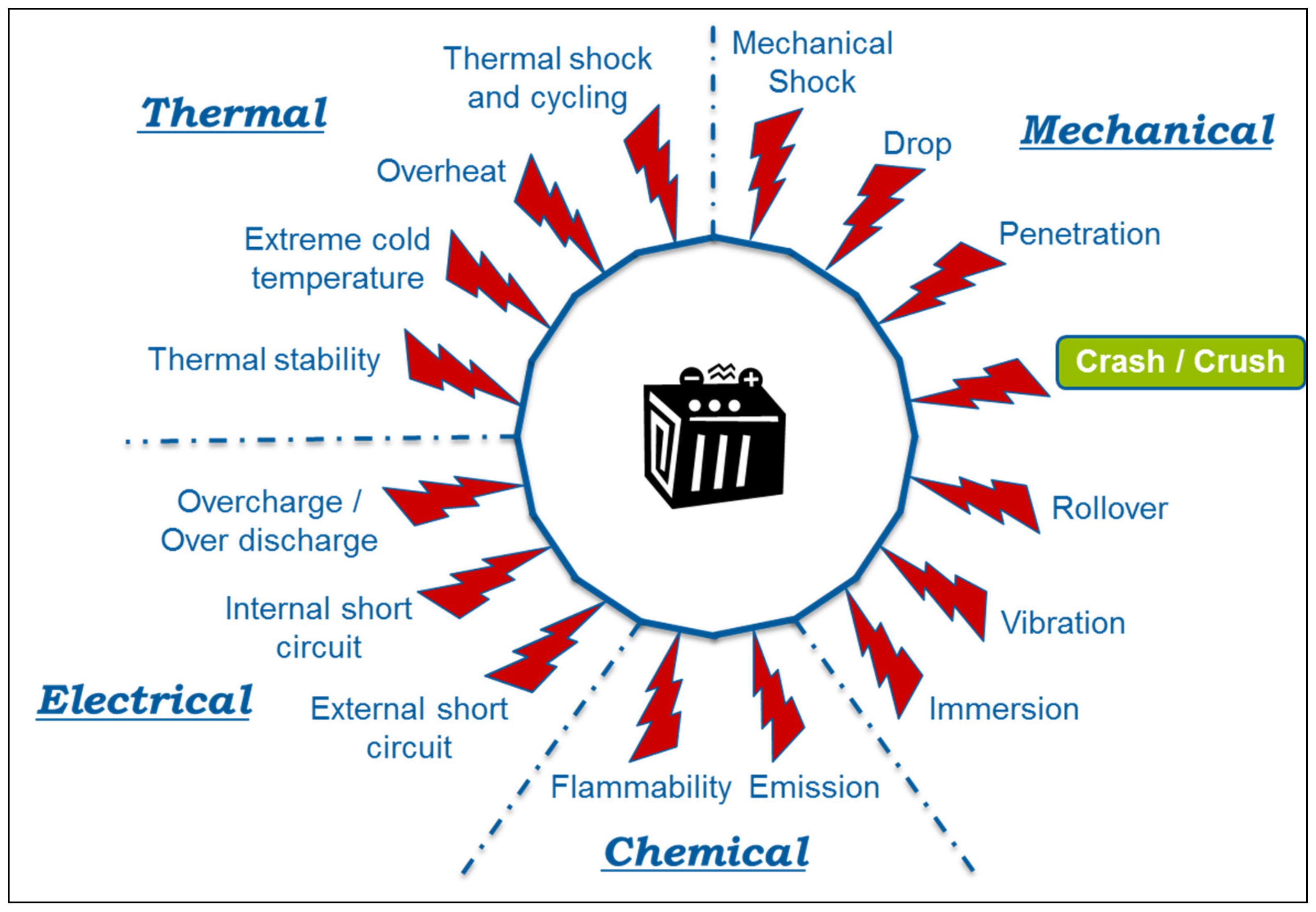
- Internal cell short circuit: This kind of severe event can happen abruptly and without any pre-warning. Zhao et. al. and Larsson found that this event can occur because of multiple reasons such as mechanical deformation or manufacturing faults. They also noticed that another reason for an internal short circuit can be the dendrite formation within the cells [27,28]. According to Ahlberg Tidblad [29], this is a particularly disturbing cause because this type of failure occurs in batteries that are complied with industry standards;
- 2.
- Mechanical deformation and impact: This cause can easily initiate an internal short circuit which consequently leads to a fire. Acute deformation can be due to certain types of crashes or ground surface conditions. Zhu et al. noted that battery packs are susceptible to penetration due to side collisions and road debris impacts [30]. The research conducted by Trattnig and Leitgeb [31] showed that the absolute scenario in a car crash can be the amalgamation of leaking fluid or gases near ignition sources like electrical arcs and/or hot surfaces;
- 3.
- Charge: The purpose for which the batteries are tailored is to collect a specific amount of energy over a definite period of time. In the instances where limits are surpassed, due to rapid charging or overcharging, the battery performance can degrade, or it can even fail completely [26];
- 4.
- Discharge: Over discharge occurs when the battery cells are discharged below their manufacturer recommended minimum voltage. During this process, the conductive copper particles are released in the electrolyte, which consequently leads to an internal short circuit of the battery. Usually, battery safety systems are there to stop such situations. However, if such a safety system fails or the battery is abused, there is a possibility of battery failure [32];
- 5.
- External short circuit: This type of the short circuit also falls under the category of an electric abuse, which can easily destabilise the battery. An external short circuit happens when the battery faces an impact and/or deformation [26];
- 6.
- High-temperature exposure: In real-time applications, the battery needs to be cooled during its operation: however, if the ambient temperature is higher than the internal temperature, battery decomposition mechanisms are triggered causing the battery to produce extreme levels of heat. This high level of heat can result in an internal short circuit or thermal runaway, which consequently reduces the safety margin [26];
- 7.
- Thermal runaway: In a battery, when exothermic chemical reactions are producing more heat than is being dissipated, it enters the thermal runaway condition. In case of severe accidents, because of thermal runaway, the battery can emit heat/fumes, catch fire, or in a worst-case scenario explode [6,24,33,34,35,36].
2. Standards and Regulations
2.1. Standards
2.1.1. European
2.1.2. International
2.1.3. National
2.2. Regulations
2.2.1. European
2.2.2. International
2.2.3. National
3. Abuse Testing: Crush Test
3.1. Procedure
3.2. Crush Speed
3.3. State of Charge (SoC)
3.4. Press Position
3.5. Crusher Shape and Dimensions
3.6. Number of Testing Samples
4. Results and Discussion
- 1.
- Procedure: The primary aspect of all the abuse tests is to define the stop criteria where the test limits are reached, and the testing can be stopped. After analysing the selected standards and regulations, it is found that there is a significant difference in the overall procedure as well as the criteria such as force, voltage, deformation, and HSL. For example, SAE J2464:2009 [89] has a simple procedure in which the formula is to multiply the weight of TD with the constant value of 1000. The same formula is also adopted by FreedomCAR:2006 [92], but with an additional deformation parameter which is equal to 50%. Comparing these with ISO 12405-3:2014 [84], UN/ECE-R100.02:2013 [98], and GTR 20:2018 [108], it is found that the force should be between 100 kN and 105 kN and does not consider the deformation. While on the other hand, IEC 62660-2:2010 [87] and GB/T 31485-2015:2015 [90] consider the voltage as an additional parameter to force and deformation. SAND 2017-6925:2017 [107] takes this one step further by providing HSL limits as well to stop the tests.Therefore, it can be said that there is some degree of commonality between standards such as SAE andFreedomCAR:2006, but when all the selected standards and regulations are compared with each other, it is fair to say that the manufacturers face challenges to decide which standard or regulation needs to be followed as they all have a variety of procedures and stop criteria parameters;
- 2.
- Crushing Speed: It is a well-known fact that the deformation of the cell differs from the battery module or pack. The failure of the battery module or pack is induced by the non-uniform deformation inside each cell that generates a vulnerable zone near the gap among cells. From Section 3.2 it can be seen that the standards and regulations differ significantly, as the impactor speed for cells ranges from 0.5 mm/min as stated in the SAE J2464:2009 [89] to 360 mm/min as per GB/T 31485-2015:2015 [90]. In terms of module and pack level testing, the impactor speed ranges from 1 mm/min to 360 mm/min. On the other hand, some of the standards such as ISO 12405-3:2014 [84], IEC 62660-2:2010 [87] FreedomCAR:2006 [92], GTR 20:2018 [108] and, UN/ECE-R100.02:2013 [98] have not provided any information regarding the impactor speed.Moreover, all the standards and regulations are based on quasi-static testing (impactor is forced on the battery) and do not undertake the realistic dynamic situation where the EV carrying battery can crush with other vehicles, i.e., other vehicles can be compared with an impactor in such a situation. Under a quasi-static situation, homogeneous deformation can be noticed within the packed batteries and battery failure distribution is in a random pattern. Conversely, in the case of dynamic impact, row by row crushing of packed batteries can be observed with force concentrating at some certain rows that result in severe deterioration of the batteries under the equal crushing displacement, implicating higher failure risk. Based on the dynamic battery test, it was found that the crushing speed dominates the failure behaviour rather than crushing energy [111]. The failure displacement declines as the crushing speed exceed 1,200,000 mm/min. Kisters et al. also found that the crushing speed has a significant influence on the failure behaviour of the TD [116]. They experimentally evaluated that a high-speed crush test (300,000 mm/min) has a double-stage failure process with an insignificant voltage drop before the load reaches its maximum and a radical voltage drop to almost 0 V at the maximum load, while a low-speed crush test (6 mm/min) has a single-stage failure process with one sharp voltage drop to zero before reaching the maximum load.Moreover, it is crucial to note that the absence of impactor crush speed value in some standards and regulations can yield inconclusive or discrepant results for quasi-static tests.Henceforth, it can be said that the current standards and regulations need to be harmonised because (a) the currently available impactor crush speed values vary drastically from each other, as well as (b) the unavailability of these values in some standards and regulations can be inconclusive and cause discrepancy in the results. In addition, it is important to note that there is a need for a dynamic testing approach that resembles the real-time situation of the EV crash;
- 3.
- SoC: SoC performs a significant role in battery failure, hence, it becomes crucial to understand SoC-based mechanical behaviour while studying the crashworthiness of EV batteries, especially in the operation situation when the electrochemical cycle occurs and the SoC value is above zero [23]. Such differences in SoC values during the tests are of high relevance because Wang et al. found that the mechanical properties of a TD vary with its SoC [23]. Moreover, according to Wang et al. a TD faces mechanical hardening with an increase in SoC [10,23], thus increasing the amount of force required to achieve the same intrusion. Sheikh and Wang et al. observed that at a higher SoC, the voltage drop occurs at lower levels of intrusion [23,117].Despite the SoC value having such importance, it can be seen from Section 3.3. that the value is mostly recommended to be 100% during the tests. One of the standards and regulations such as ISO 12405-3:2014 [84] and UN/ECE-R100.02:2013 [98] have their conditions, though, it does not provide a variety of SoC values under which the battery should be tested. IEC 62660-2:2010 [87] categorizes SoC for testing based on the vehicle type (BEV and HEV) and does not consider the range of SoCs over which the batteries shall be tested.Henceforth, evaluating the standards and regulations against the literature, it can be said that there is a need for tests that undertake a variety of SoC values while approving the EV battery, i.e., rather than just doing the test as per one value (100% SoC);
- 4.
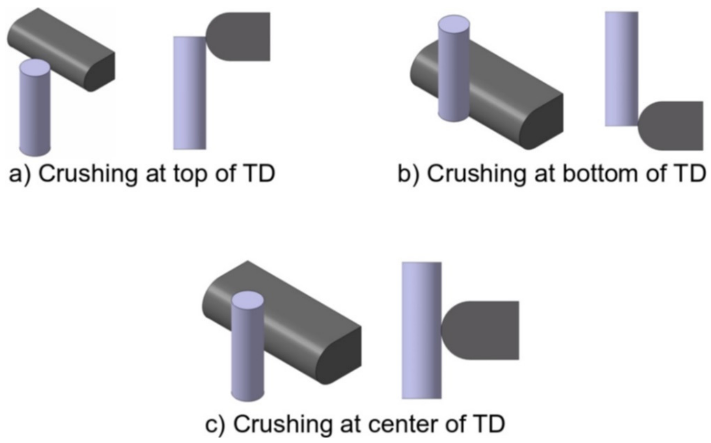
- Press position: Considering the press position while carrying out the crush test is of high importance. Maleki and Haward had carried out the research on various crush positions and demonstrated that the slight damage at the edge of the prismatic cell has a higher probability to lead to thermal runaway than crushing the cell at flat face [118]. The exponent observed similar behaviour during the testing. They represented that the mechanical deformation/damage at the edge of the cell has higher chances of thermal runaway compare with damage perpendicular to the electrode surface [112]. Thus, considering various press positions for testing becomes crucial.The studies of the standards and regulations show that there is no clear information provided in terms of the exact location of the impactor that presses the cell, module, or pack, i.e., it can be anywhere, top, bottom, or centre (refer Figure 11). Moreover, some of the current standards such as SAE J2464:2009 [89], FreedomCAR:2006 [92], SAND2017-6925:2017 [107], and GB/T 31485-2015:2015 [90] are quite ambiguous as they only mention the “vulnerable” and “susceptible” position of the battery but do not define the position clearly. Similar ambiguity is noticed further in GB/T 31485-2015:2015 [90] in terms of polar plates which need to be considered while testing the cells, i.e., no description is provided about the polar plate.Henceforth, it can be said that the information provided on the press position needs to be improved [113] and certainly the decision should not be left to the manufacturers and technical services as mentioned by UN/ECE-R100.02:2013 [98] and GTR 20:2018 [108]. Moreover, there should be some in-depth information considering cell, module, and pack level testing;
- 5.
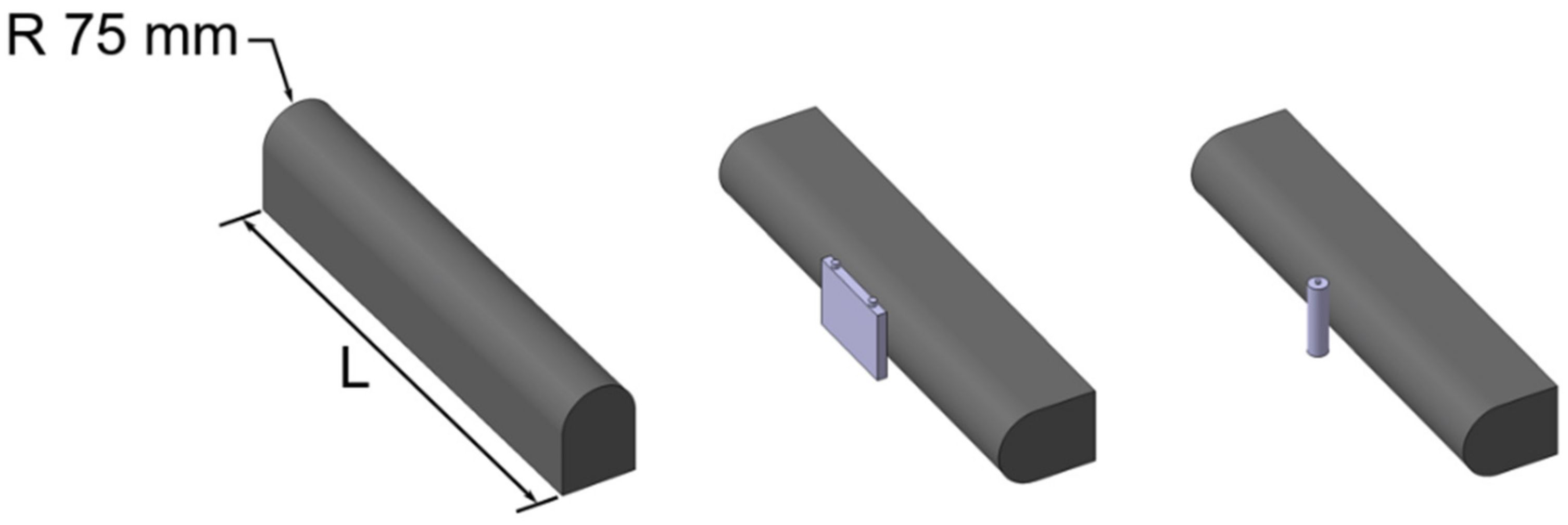
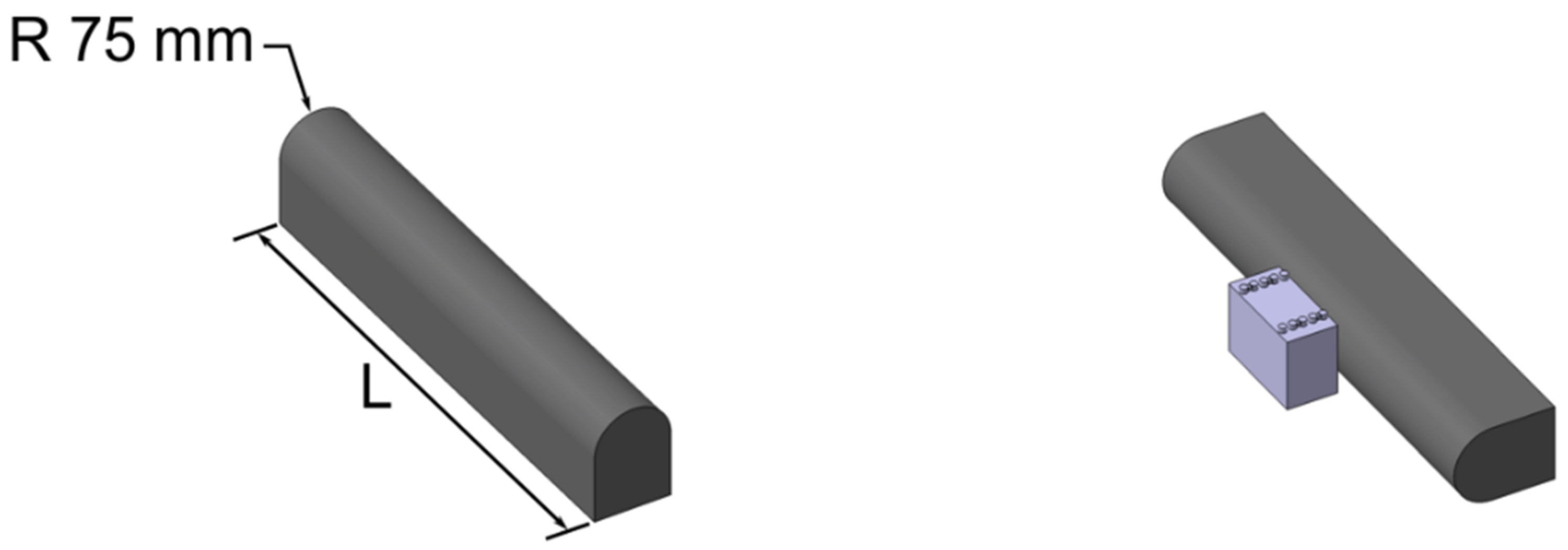
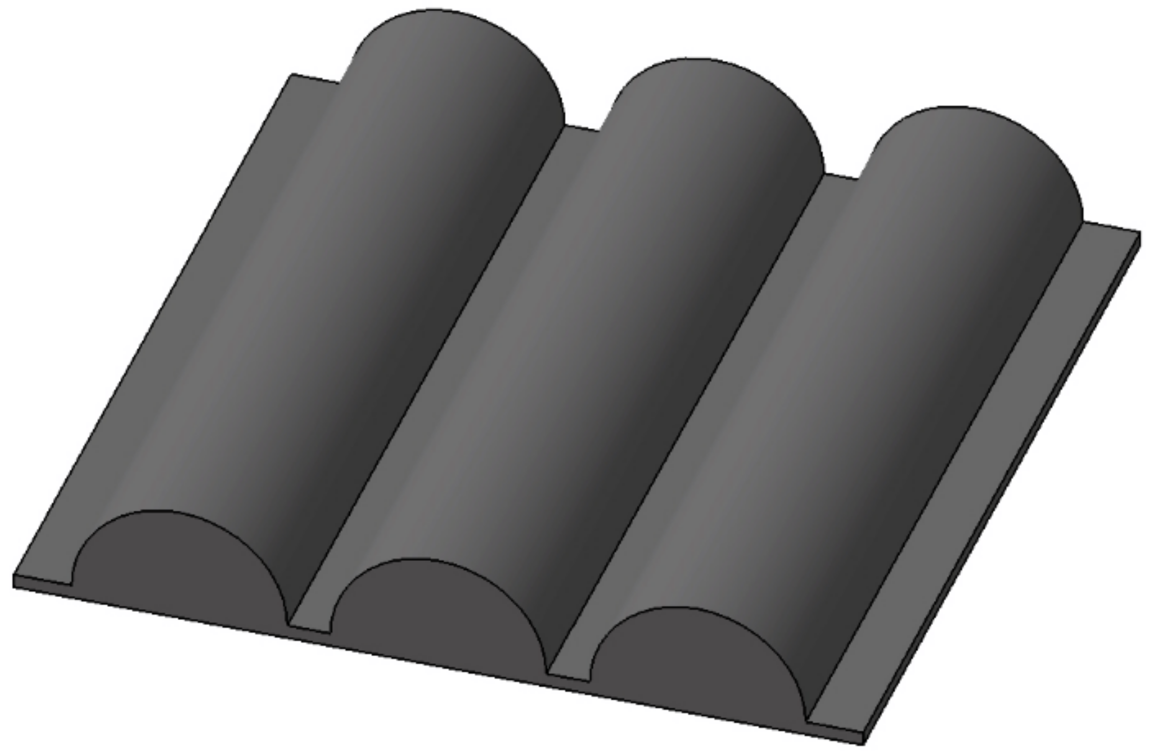
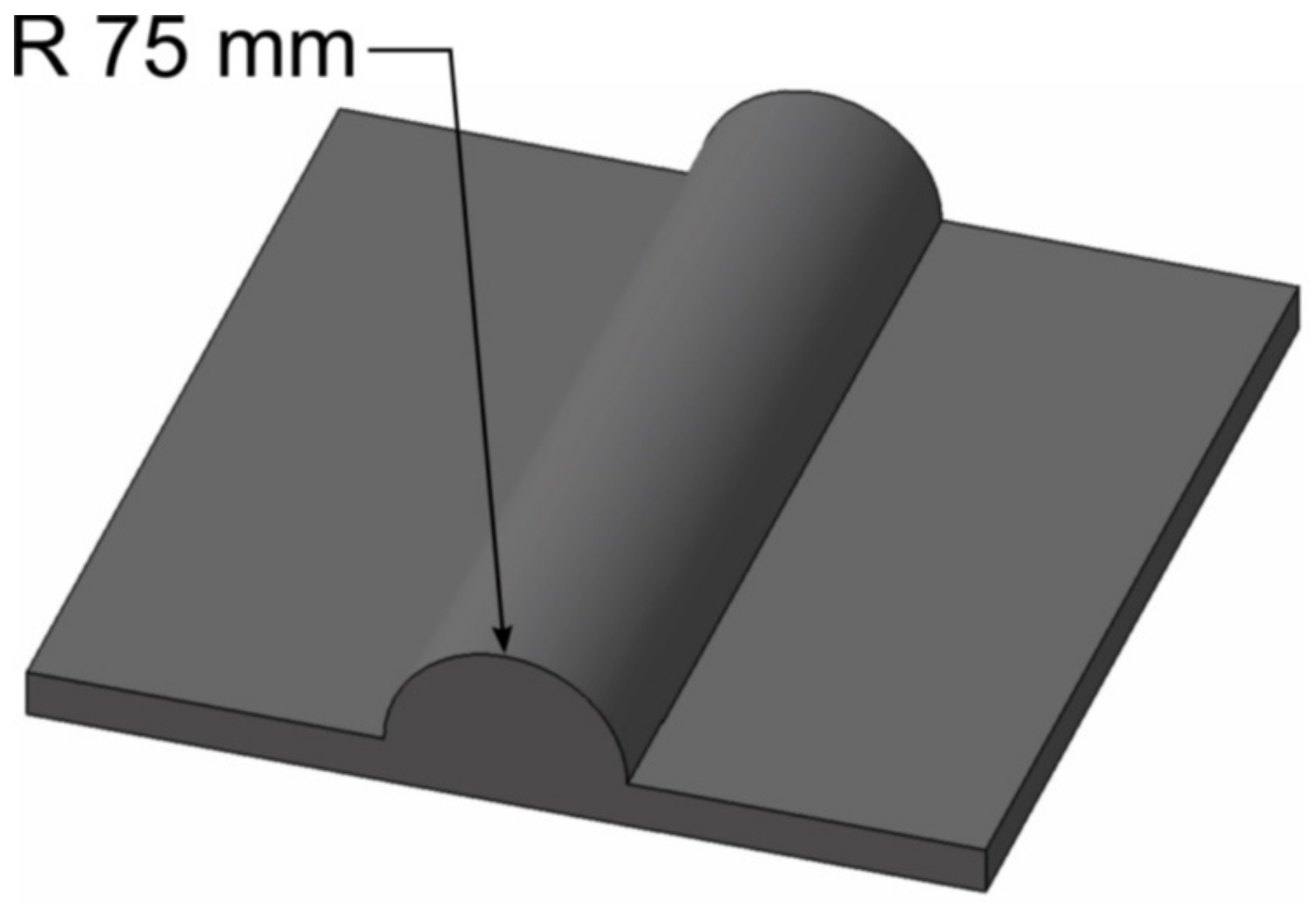
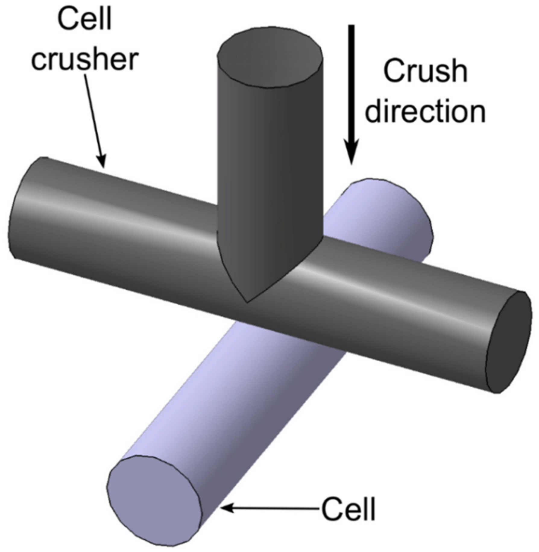
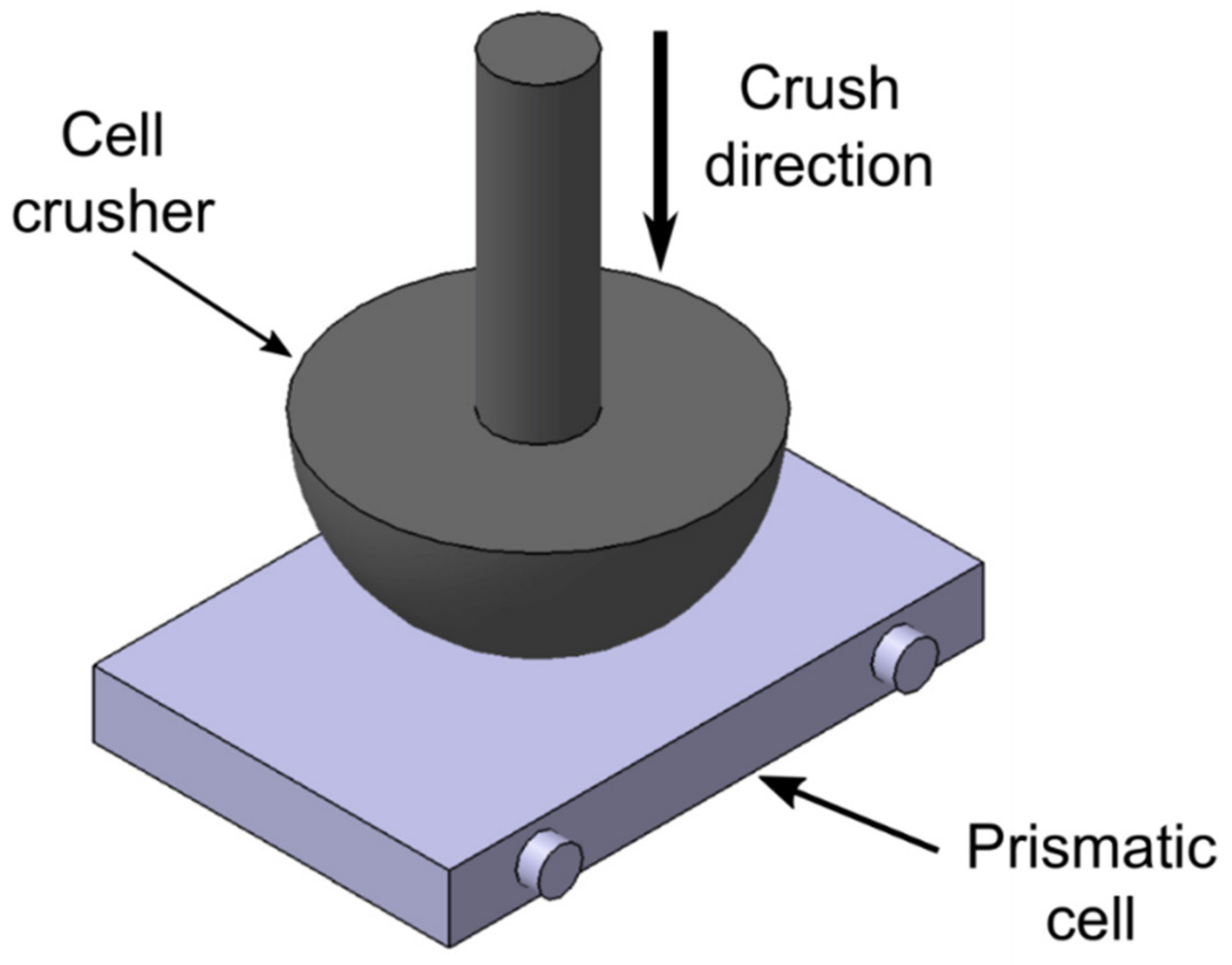
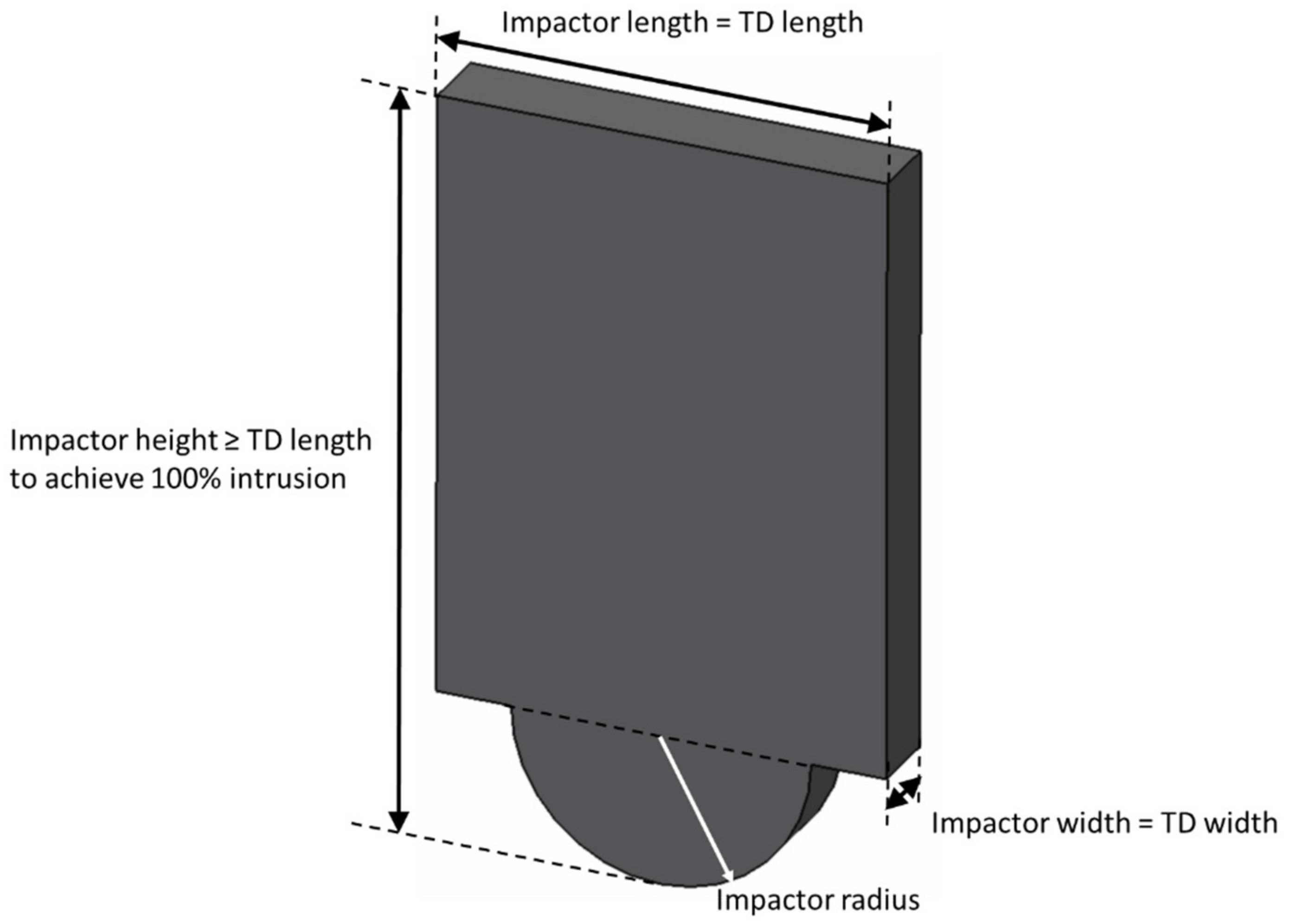
- Crusher shape and dimensions: In terms of impactor shape/design, it was noticed that to test the battery module and pack, the shape of the impactor remains the same for GTR 20:2018 [108], FreedomCAR:2006 [92], SAE J2464:2009 [89], UN/ECE-R100.02:2013 [98] and ISO 12405-3:2014 [84], while SAND2017-6925:2017 [107] differs in terms of the number of semi-cylinders on the plate and IEC 62660-2:2010 [87] does not provide any such information. Though, it is worthwhile to note that IEC 62660-2:2010 [87] defines the shape/design of the impactor for a cylindrical cell which is similar to SAE J2464:2009 [89], SAND2017-6925:2017 [107], and FreedomCAR:2006 [92]. IEC 62660-2:2010 [87] and SAND2017-6925:2017 [107] also provide specific shape/design of the impactor for prismatic cells, whilst in GB/T 31485-2015:2015 [90] the impactor shape is completely different from all the standards and regulations. In regards to the dimensions of the impactor, it is different in all the selected standards and regulations.Henceforth, the standards and regulations must have a clearly defined shape/design and the dimension of the impactor for testing cell, module, and pack for different types of batteries such as cylindrical and prismatic;
- 6.
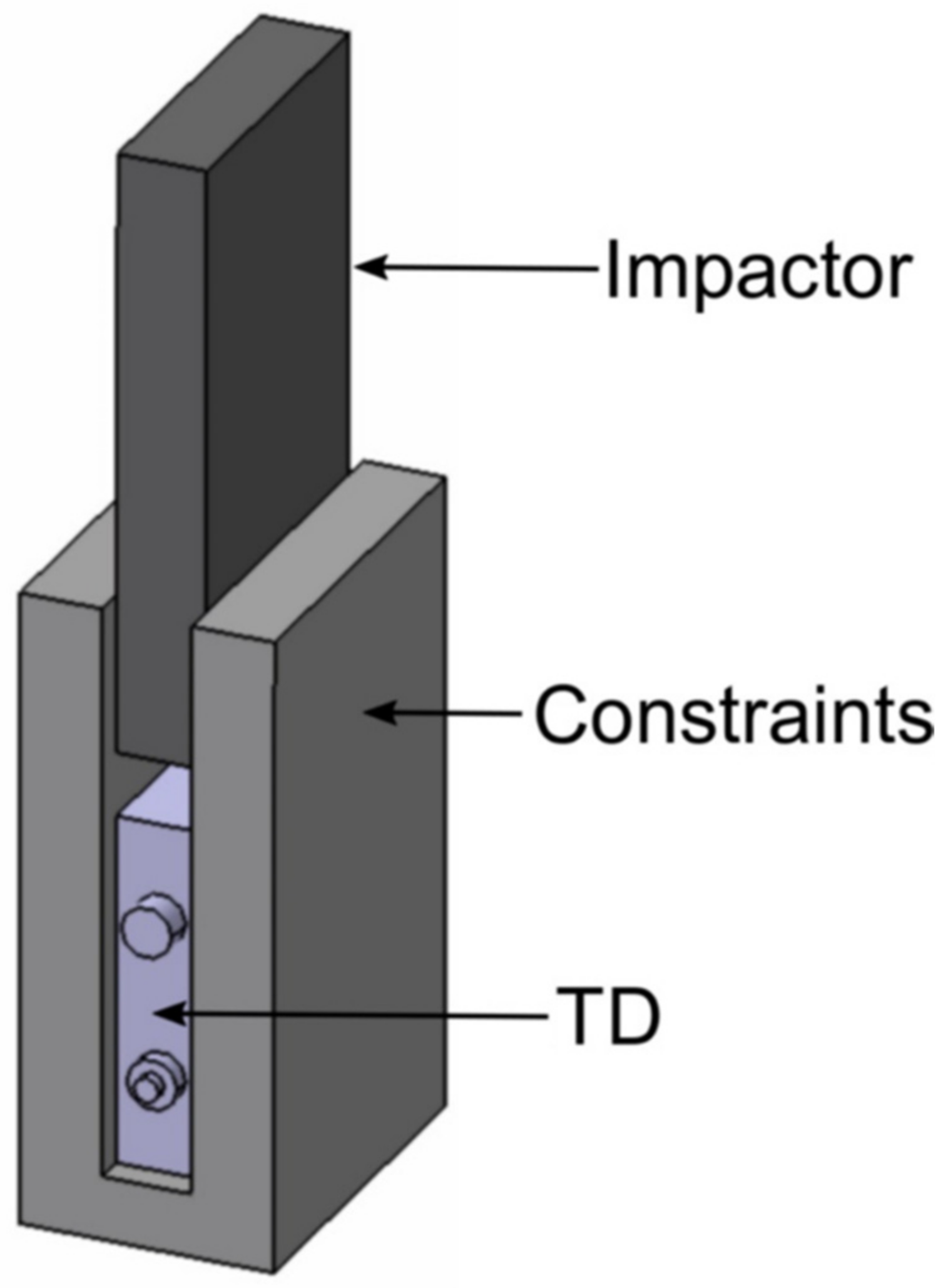
- Number of testing samples: Multiple samples are needed for each test during the testing and in the majority of cases, the testing degrades the TD and therefore reusing the samples is not acceptable [115]. However, after considering the selected standards and regulation, it can be identified that standards such as SAE J2464:2009 [89] and FreedomCAR:2006 [92] overlap each other up to a certain extent but vary significantly in terms of the TD axes during the test. Comparing these two standards with GB/T 31485-2015:2015 [40] and SAND2017-6925:2017 [107], it is found that there is no clarity in terms of cell, module, or pack level testing samples. Considering the ISO 12405-3:2014 [84] standard there is a freedom to opt for the regional regulation but the axes should be defined by manufacturers which is certainly bewilderment for the manufacturers. In addition, UN/ECE-R100.02:2013 [98], IEC 62660-2:2010 [87] and, GTR 20:2018 [108] lack such information of sampling.Henceforth, it can be said that despite the government and associated standards and regulations developing bodies being aware of the situation of confusion among the battery manufacturers along with the concept of increment in the cost linked with the number of test samples, there is no clear guidance for the manufacturers available.

- Impact forces from the contact of the vehicle with the collision partner:Here it is difficult to analyse the kind of collision and the impact severity. During the crash acceleration and specifically deceleration, values can be significantly high. For example, in a crash test carried out by the University of Zilinia, the deceleration of an accumulator mounted at the rear of the vehicle was approximately 500 m/s2 in an impact with a rigid concrete barrier at a speed of 54 km/h (refer Figure 12) [121]. In such a scenario, the batteries are dynamically loaded, and even if no mechanical damage is displayed on the surface of the battery, there is often internal damage that takes a relatively long time to show its effect;
- The intrusion of the other parts or deformation of the battery:In this case, the static test provides a good approximation of reality. The battery and vehicle construction play an vital role along with the placement of battery and fastening system [121].
5. Conclusions
Author Contributions
Funding
Institutional Review Board Statement
Informed Consent Statement
Data Availability Statement
Conflicts of Interest
Abbreviations
| ANL | Argonne National Laboratory |
| BEVs | Battery Electric Vehicles |
| C | Cell |
| CDR | Crash Data Recorder |
| CEN | European Committee for Standardisation |
| CENELEC | European Committee for Electrotechnical Standardization |
| CNG | Compressed Natural Gas |
| DC | Direct-Current |
| DoE | The United States Department of Energy |
| ECHA | European Chemical Agency |
| ECOSOC | The United Nations Economic and Social Council |
| EESS | Electrical Energy Storage System |
| ESOs | European Standards Organizations |
| EU | Europe |
| EV | Electric Vehicle |
| EVs | Electric Vehicles |
| EVS | Electric Vehicle Safety |
| FMVSS | Federal Motor Vehicle Safety Standards |
| H | Height |
| HE | High Energy |
| HEVs | Hybrid Electric Vehicles |
| HP | High Power |
| HSL | Hazard Safety Level |
| ICE | Internal Combustion Engines |
| IEA | International Energy Agency |
| IEC | International Electrotechnical Commission |
| ILTVA | International Light Transportation Vehicle Association |
| INEEL | Idaho National Engineering and Environmental Laboratory |
| INEL | Idaho National Engineering Laboratory |
| ISO | International Organisation for Standardisation |
| JRC | Joint Research Centre |
| L | Length |
| LFP | Lithium Iron Phosphate |
| LNG | Liquefied Natural Gas |
| M | Module |
| NHTSA | National Highway Traffic Safety Administration |
| P | Pack |
| R | Radius |
| REACH | Regulation on the Registration, Evaluation, Authorisation and Restriction of Chemicals |
| REESS | Rechargeable Energy Storage System |
| Reg | Regulation |
| RESS | Rechargeable Energy Storage System |
| SAC | Standardization Administration of China |
| SAE | Society of Automotive Engineers International |
| SNL | Sandia National Laboratory |
| SoC | State of charge |
| Std | Standard |
| T | Thickness |
| TC | Technical Committee |
| TD | Test Device |
| UNECE | United Nations Economic Commission for Europe |
| UNECE | United Nations Economic Commission for Europe |
| US | United States |
| USA | United States of America |
| USABC | United States Advanced Battery Consortium |
| W | Width |
References
- Wu, S.; Xiong, R.; Li, H.; Nian, V.; Ma, S. The state of the art on preheating lithium-ion batteries in cold weather. J. Energy Storage 2020, 27, 101059. [Google Scholar] [CrossRef]
- Zhang, Q.; Dong, Q.-F.; Zheng, M.-S.; Tian, Z.-W. Electrochemical Energy Storage Device for Electric Vehicles. J. Electrochem. Soc. 2011, 158, A443. [Google Scholar] [CrossRef]
- Kotak, B.; Kotak, Y. Review of E European Regu ulations and Germany’s Action to Reduce Automotive Sector Emissions. Trasp. Eur. 2016, 7, 1–19. [Google Scholar]
- Wegmann, R.; Döge, V.; Becker, J.; Sauer, D.U. Optimized operation of hybrid battery systems for electric vehicles using deterministic and stochastic dynamic programming. J. Energy Storage 2017, 14, 22–38. [Google Scholar] [CrossRef]
- Bandhauer, T.M.; Garimella, S.; Fuller, T.F. A Critical Review of Thermal Issues in Lithium-Ion Batteries. J. Electrochem. Soc. 2011, 158, R1. [Google Scholar] [CrossRef]
- Spray, R.; Barry, M.; Vickery, J. Understanding Downstream Risk from Lithium-Ion Battery Thermal Runaway & Designing for Safety. ECS Trans. 2019, 89, 65–71. [Google Scholar] [CrossRef]
- Visintin, A.; Thomas, J.E.; Becker, M.D.; Castro, B.; Milocco, R.; Real, S.; Sacco, J.; Garaventta, G.N.; Triaca, W.E. (Keynote Lecture) The Research on Lithium-Ion Batteries for Electric Cars in the Universidad Nacional de La Plata. ECS Trans. 2019, 40, 67–73. [Google Scholar] [CrossRef]
- Messier, P.; Nguyễn, B.-H.; LeBel, F.-A.; Trovão, J.P.F. Disturbance observer-based state-of-charge estimation for Li-ion battery used in light electric vehicles. J. Energy Storage 2020, 27, 101144. [Google Scholar] [CrossRef]
- Alessandrini, S.; Rizzuto, E.; Del Prete, Z. Characterizing different types of lithium ion cells with an automated measurement system. J. Energy Storage 2016, 7, 244–251. [Google Scholar] [CrossRef]
- Wang, W.; Yang, S.; Lin, C. Clay-like mechanical properties for the jellyroll of cylindrical Lithium-ion cells. Appl. Energy 2017, 196, 249–258. [Google Scholar] [CrossRef]
- Hawkins, T.R.; Singh, B.; Majeau-Bettez, G.; Strømman, A.H. Comparative Environmental Life Cycle Assessment of Conventional and Electric Vehicles. J. Ind. Ecol. 2013, 17, 53–64. [Google Scholar] [CrossRef]
- Malifarge, S.; Delobel, B.; Delacourt, C. Experimental and Modeling Analysis of Graphite Electrodes with Various Thicknesses and Porosities for High-Energy-Density Li-Ion Batteries. J. Electrochem. Soc. 2018, 165, A1275–A1287. [Google Scholar] [CrossRef]
- Mohanty, P.; Kotak, Y. Electric vehicles: Status and roadmap for India. In Electric Vehicles: Prospects and Challenges; Muneer, T., Kolhe, M.L., Doyle, A., Eds.; Elsevier Inc.: Amsterdam, The Netherlands, 2017; pp. 387–414. [Google Scholar]
- Machuca, E.; Steger, F.; Vogt, J.; Brade, K.; Schweiger, H.G. Availability of Lithium Ion Batteries from Hybrid and Electric Cars for Second Use: How to Forecast for Germany until 2030. J. Electr. Eng. 2018, 6, 129–143. [Google Scholar] [CrossRef]
- Schweiger, H.-G. Zukunft in Bewegung—Automobile Antriebskonzepte in der Diskussion 2019. Available online: https://www.researchgate.net/publication/333868327_Elektromobilitat_Aktueller_Stand_und_Ausblick (accessed on 10 June 2021).
- Vaughan, A.; Electric Cars Exceed 1 m in Europe as Sales Soar by More Than 40%. The Guard. Available online: https://www.theguardian.com/environment/2018/aug/26/electric-cars-exceed-1m-in-europe-as-sales-soar-by-more-than-40-per-cent#top (accessed on 10 April 2021).
- Shell Deutschland Oil GmbH. Shell Passenger Car SCenarios for Germany to 2040; Shell Deutschland Oil GmbH: Hamburg, Germany, 2014. [Google Scholar]
- Kugler, U.; Schimeczek, C.; Klötzke, M.; Schmid, S.; Gis, W.; Järvi, T.; Auvinen, H. Scenario Report, with an in-Depth Description of the Scenarios’ Background (D 6.2); eMap—German Aerospace Center (DLR), Motor Transport Institute (ITS) & Technical Research Centre of Finland Ltd. (VTT): Stuttgart, Germany, 2015. [Google Scholar]
- IEA. Global EV Outlook 2020; IEA: Paris, Frence, 2020. [Google Scholar]
- Power Technology. The Most Promising Renewable Trends for Electric Vehicles. Available online: https://www.power-technology.com/comment/promising-renewable-trends-electric-vehicles/ (accessed on 2 April 2021).
- Khan, B. The World Is on the Brink of an Electric Car Revolution. Available online: https://www.climatecentral.org/news/world-electric-car-revolution-21597 (accessed on 5 April 2021).
- Spielbauer, M.; Berg, P.; Ringat, M.; Bohlen, O.; Jossen, A. Experimental study of the impedance behavior of 18650 lithium-ion battery cells under deforming mechanical abuse. J. Energy Storage 2019, 26, 101039. [Google Scholar] [CrossRef]
- Wang, W.; Yang, S.; Lin, C.; Li, Y. Mechanical and electrical response of cylindrical Lithium-ion cells at various State of Charge. Energy Procedia 2018, 145, 128–132. [Google Scholar] [CrossRef]
- Goodman, J.K.S.; Miller, J.T.; Kreuzer, S.; Forman, J.; Wi, S.; Choi, J.; Oh, B.; White, K. Lithium-ion cell response to mechanical abuse: Three-point bend. J. Energy Storage 2020, 28, 101244. [Google Scholar] [CrossRef]
- Pan, Z.; Li, W.; Xia, Y. Experiments and 3D detailed modeling for a pouch battery cell under impact loading. J. Energy Storage 2020, 27, 101016. [Google Scholar] [CrossRef]
- Bisschop, R.; Willstrand, O.; Amon, F.; Rosengren, M. Fire Safety of Lithium-Ion Batteries in Road Vehicles; RISE Research Institutes of Sweden: Gothenburg, Sweden, 2019. [Google Scholar]
- Zhao, W.; Luo, G.; Wang, C.-Y. Modeling Internal Shorting Process in Large-Format Li-Ion Cells. J. Electrochem. Soc. 2015, 162, A1352–A1364. [Google Scholar] [CrossRef] [Green Version]
- Larsson, F. Lithium-ion Battery Safety-Assessment by Abuse Testing, Fluoride Gas Emissions and Fire Propagation. Ph.D. Thesis, Chalmers University of Technology, Gothenburg, Sweden, 2017. [Google Scholar]
- Santhanagopalan, S.; Ramadass, P.; Zhang, J. Analysis of internal short-circuit in a lithium ion cell. J. Power Sources 2009, 194, 550–557. [Google Scholar] [CrossRef]
- Zhu, J.; Wierzbicki, T.; Li, W. A review of safety-focused mechanical modeling of commercial lithium-ion batteries. J. Power Sources 2018, 378, 153–168. [Google Scholar] [CrossRef]
- Trattnig, G.; Leitgeb, W. Battery Modelling for Crash Safety Simulation. In Automotive Battery Technology; Springer International Publishing: Berlin/Heidelberg, Germany, 2014; pp. 19–35. [Google Scholar]
- Hendricks, C.; Williard, N.; Mathew, S.; Pecht, M. A failure modes, mechanisms, and effects analysis (FMMEA) of lithium-ion batteries. J. Power Sources 2015, 297, 113–120. [Google Scholar] [CrossRef] [Green Version]
- Li, W.; Xia, Y.; Chen, G.; Sahraei, E. Comparative study of mechanical-electrical-thermal responses of pouch, cylindrical, and prismatic lithium-ion cells under mechanical abuse. Sci. China Technol. Sci. 2018, 61, 1472–1482. [Google Scholar] [CrossRef]
- Jeevarajan, J.A.; Hall, A. Study of the Intrinsic Safety Features in a Cylindrical Li-Ion Cell. ECS Trans. 2019, 1, 1–5. [Google Scholar] [CrossRef]
- Liao, Z.; Zhang, S.; Li, K.; Zhao, M.; Qiu, Z.; Han, D.; Zhang, G.; Habetler, T.G. Hazard analysis of thermally abused lithium-ion batteries at different state of charges. J. Energy Storage 2020, 27, 101065. [Google Scholar] [CrossRef]
- Mier, F.A.; Morales, R.; Coultas-McKenney, C.A.; Hargather, M.J.; Ostanek, J. Overcharge and thermal destructive testing of lithium metal oxide and lithium metal phosphate batteries incorporating optical diagnostics. J. Energy Storage 2017, 13, 378–386. [Google Scholar] [CrossRef]
- Gehandler, J.; Karlsson, P.; Vylund, L. Risks Associated with Alternative Fuels in Road Tunnels and Underground Garages; SP Technical Research Institute of Sweden: Borås, Sweden, 2017. [Google Scholar]
- Danish Maritime Accident Investigation Board. Pearl of Scandinavia Fire-Marine Accident Report; Danish Maritime Accident Investigation Board: Copenhagen, Denmark, 2010. [Google Scholar]
- Auto Web Hangzhou Halts All Electric Taxis as a Zotye Langyue (Multipla) EV Catches Fire. Available online: http://chinaautoweb.com/2011/04/hangzhouhalts-all-electric-taxis-as-a-zotye-langyue-multipla-ev-catches-fire/ (accessed on 15 December 2020).
- Smith, B. Chevrolet Volt Battery Incident Summary Report; US Department of Transportation, National Highway Traffic Safety Administration: Washington, DC, USA, 2012.
- Sturk, D.; Hoffmann, L. E-Fordons Potentiella Riskfaktorer vid Trafikskadehändelse; SP Technical Research Institute of Sweden: Borås, Sweden, 2013. [Google Scholar]
- Voelcker, J. Second Fisker Karma Fire Casts Fresh Doubt on Plug-In Hybrid. Available online: https://www.greencarreports.com/news/1078412_second-fisker-karma-fire-casts-fresh-doubt-on-plug-in-hybrid (accessed on 13 January 2021).
- Garthwaite, J. Mystery at Port Newark: Why Did 17 Plug-In Cars Burn? Available online: https://wheels.blogs.nytimes.com/2012/11/02/mystery-at-port-newark-why-did-17-plug-in-cars-burn/ (accessed on 12 February 2021).
- McPartland, B. Paris Autolib’ Electric Cars Go up in Smoke. Available online: https://www.thelocal.fr/20131014/in-images-two-autolib-cars-go-up-in-smoke-in-paris/ (accessed on 10 April 2021).
- Godfrey, W. Investigation: PE 13-037-Fire-Propulsion Battery-Road Debris. 2014. Available online: https://www.autosafety.org/wp-content/uploads/import/Tesla Battery Closing Memo.pdf (accessed on 13 March 2021).
- Loveday, E. Mitsubishi Extends Production Halt on Outlander PHEV as Perplexing Battery Investigation Continues. Available online: https://insideevs.com/news/317625/mitsubishi-extends-production-halt-on-outlander-phev-as-perplexing-battery-investigation-continues/ (accessed on 15 March 2021).
- Lopez, L. Another Tesla Caught On Fire While Sitting in a Toronto Garage This Month. Available online: https://www.businessinsider.in/another-tesla-caught-on-fire-while-sitting-in-a-toronto-garage-this-month/articleshow/30366384.cms (accessed on 20 March 2021).
- Bolstad, K.; Urstad, T. Personbil Påkjørt Av Toget i Råde. Available online: https://www.moss-avis.no/nyheter/rade/togulykker/personbil-pakjort-av-toget-i-rade/s/5-67-193113 (accessed on 29 March 2021).
- Brandt, P. Brandorsaken Hos Tesla Model S i Norge Klarlagd—Kortslutning. Available online: https://www.mestmotor.se/automotorsport/artiklar/nyheter/20160319/brandorsaken-hos-tesla-model-s-i-norge-klarlagd-kortslutning/ (accessed on 10 March 2021).
- Lambert, F. Tesla Says Model S Fire in France Was Due to ‘Electrical Connection Improperly Tightened’ by a Human Instead of Robots. Available online: https://electrek.co/2016/09/09/tesla-fire-france-electrical-connection-improperly-tightened-human-robot/ (accessed on 3 April 2021).
- Evans, A. Electric Car Bursts into Flames and Burns to the Ground after it was Left Charging Overnight ’at a Faulty Power Point. Available online: https://www.dailymail.co.uk/news/article-4679416/Electric-car-left-chargingovernight-destroyed-fire.html (accessed on 1 March 2021).
- Lambert, F. (a) Tesla Owner Asks for $1 Million after Model X Caught on Fire in Crash and Falcon Wing Doors Wouldn’t Open. Available online: https://electrek.co/2017/04/23/tesla-model-x-fire-crash-falcon-wing-doors-stuck/ (accessed on 17 June 2021).
- Barth, T.; Robert, S. NTSB Investigations of EV Fires Electric Vehicle Safety IWG Global Technical Regulation Session 16. Available online: https://wiki.unece.org/download/attachments/60358932/EVS16-E7OI-0600 %5BUS%5DNTSB electric vehicle fire investigations.pdf?api=v2 (accessed on 25 June 2021).
- Online Reporters Porsche Catches Fire while Charging. Available online: https://www.bangkokpost.com/news/general/1429518/porsche-catches-firewhile-charging (accessed on 2 April 2021).
- Brandt, P. Jaguar I-Pace Fattade Eld i Nederländerna—Beskrivs Som “Termisk Incident”. Available online: https://www.mestmotor.se/recharge/artiklar/nyheter/20181211/jaguar-i-pace-fattade-eld-i-nederlanderna-beskrivs-som-ermisk-incidentav-jaguar/ (accessed on 12 March 2021).
- Pearson-JonesBridie New Tesla Car Bursts into Flames TWICE in a Day with Firefighters Using 2000 Gallons of Water to Battle Blaze. Available online: https://www.dailymail.co.uk/news/article-6519645/Tesla-car-catches-fire-3times-one-day-firefighters-battle-blaze-2000-gallons-water.html (accessed on 26 April 2021).
- Technology Tesla Car Catches Fire in China, Investigation Underway. Available online: https://news.cgtn.com/news/3d3d514d7a416a4d34457a6333566d54/index.html (accessed on 17 March 2021).
- Loveday, S. BMW i3 REx Burns after Catching Fire while Parked in Spain. Available online: https://insideevs.com/news/337258/bmw-i3-rex-burns-after-catching-fire-while-parked-in-spain/ (accessed on 9 May 2021).
- NTSB. Preliminary Report: Crash and Post-Crash Fire of Electric-Powered Passenger Vehicle; NTSB: Washington, DC, USA, 2018. [Google Scholar]
- Zhou, X. Frequent Fire Accidents on Electric Vehicle. Operators 2018, 10, 65–66. [Google Scholar]
- NTSB. (a) Preliminary Report: Highway HWY18FH013; National Transportation Safety Board: Washington, DC, USA, 2018. [Google Scholar]
- Revill, J. Tesla Crash may have Triggered Battery Fire: Swiss Firefighters. Available online: https://www.reuters.com/article/us-swiss-tesla-crash-idUSKCN1IF2WN (accessed on 7 March 2021).
- NTSB. (b) Preliminary Report—Battery Fire in Electric-Powered Passenger Car; National Transportation Safety Board: Washington, DC, USA, 2018. [Google Scholar]
- Deick, M. Van Gloednieuwe Auto Verwoest Door Brand in Rumpt. Available online: https://www.zakengidstiel.nl/nieuws/algemeen/587262/gloednieuwe-auto-verwoest-door-brand-in-rumpt (accessed on 4 April 2021).
- Gutman, M.; Youn, S. Firefighters Work 16 Hours to Put Out Fires in Tesla Model S. Available online: https://abcnews.go.com/Technology/tesla-opens-investigation-car-burst-flames-times/story?id=59930420 (accessed on 17 March 2021).
- Jolicoeur, C. BMW i8 Catches Fire in Europe Dealership, Gets Dropped in Huge Bath. Available online: https://motorillustrated.com/bmw-i8-catches-fire-in-europe-dealership-gets-dropped-in-huge-bath/23440/ (accessed on 10 April 2021).
- Huang, E. Electric Vans from One of China’s Biggest EV Makers Are Catching Fire. Available online: https://qz.com/1575817/electric-vehicles-from-chinese-car-maker-bjev-are-catching-fire/ (accessed on 3 April 2021).
- Ke, S. Tesla Investigating Explosion of Car in Shanghai. Available online: https://www.shine.cn/news/metro/1904223436/ (accessed on 22 March 2021).
- Kermani, G.; Sahraei, E. Review: Characterization and Modeling of the Mechanical Properties of Lithium-Ion Batteries. Energies 2017, 10, 1730. [Google Scholar] [CrossRef] [Green Version]
- Zhang, M.; Liu, L.; Stefanopoulou, A.; Siegel, J.; Lu, L.; He, X.; Ouyang, M. Fusing Phenomenon of Lithium-Ion Battery Internal Short Circuit. J. Electrochem. Soc. 2017, 164, A2738–A2745. [Google Scholar] [CrossRef] [Green Version]
- Hunt, I.A.; Patel, Y.; Szczygielski, M.; Kabacik, L.; Offer, G.J. Lithium sulfur battery nail penetration test under load. J. Energy Storage 2015, 2, 25–29. [Google Scholar] [CrossRef]
- Kim, W.-K.; Steger, F.; Kotak, B.; Knudsen, P.; Girgsdies, U.; Schweiger, H.-G. Water Condensation in Traction Battery Systems. Energies 2019, 12, 1171. [Google Scholar] [CrossRef] [Green Version]
- Kotak, B. (a) Need for Safer Standards and Regulation of Lithium-Ion Battery. In Proceedings of the 10th Annual Battery Saftey Summit, Alexandria, VA, USA, 22–25 October 2019; Cambridge EnerTech: Needham, MA, USA, 2019. [Google Scholar]
- Union of Concerned Scientist Electric Vehicle Batteries: Materials, Cost, Lifespan. Available online: https://www.ucsusa.org/resources/ev-batteries#toc-materials (accessed on 19 March 2021).
- Zhao, W.; Luo, G.; Wang, C.-Y. Modeling Nail Penetration Process in Large-Format Li-Ion Cells. J. Electrochem. Soc. 2015, 162, A207–A217. [Google Scholar] [CrossRef]
- Lunz, B.; Sauer, D.U. Electric road vehicle battery charging systems and infrastructure. In Advances in Battery Technologies for Electric Vehicles; Elsevier: Amsterdam, The Netherlands, 2015; pp. 445–467. [Google Scholar]
- CEN. What Is a Standard? Available online: https://www.cen.eu/work/endev/whatisen/pages/default.aspx (accessed on 12 April 2021).
- CEN. (a) Compass; CEN—The World of European Standards; CEN: Brussels, Belgium, 2010. [Google Scholar]
- CEN. (b) Technical Bodies. Available online: https://standards.cen.eu/dyn/www/f?p=CENWEB:6:::NO::: (accessed on 19 March 2021).
- CEN. (c) CEN Deliverables. Available online: https://boss.cen.eu/reference-material/guidancedoc/pages/del (accessed on 10 April 2021).
- CEN-CENLEC About Us. Available online: https://www.cencenelec.eu/aboutus/Pages/default.aspx (accessed on 2 February 2021).
- CENLEC. CENELEC Facts and Figures. Available online: https://www.cenelec.eu/aboutcenelec/whatwedo/factsandfigures/index.html (accessed on 30 March 2021).
- Dossett, D. The European Standardization System in support of e-mobility. In Proceedings of the International Symposium ‘Towards a Transatlantic E-Mobility Market’, CEN-CENLEC, Ispra, Italy, 28–29 October 2015; pp. 1–21. [Google Scholar]
- ISO Electrically Propelled Road Vehicles—Test Specification for Lithium-Ion Traction Battery Packs and Systems—Part 3: Safety Performance Requirements—ISO 12405-3:2014. Available online: https://www.iso.org/standard/59224.html (accessed on 13 April 2021).
- CEN-CENLEC. (a) ISO & IEC. Available online: https://www.cencenelec.eu/intcoop/StandardizationOrg/Pages/default.aspx (accessed on 3 March 2021).
- ISO. (a) About US. Available online: https://www.iso.org/about-us.html (accessed on 17 May 2021).
- IEC. Secondary Lithium-Ion Cells for the Propulsion of Electric Road Vehicles—Part 2: Reliability and Abuse Testing; International Electrotechnical Commision: Geneva, Switzerland, 2018. [Google Scholar]
- IEC. (a) What We Do. Available online: https://www.iec.ch/what-we-do (accessed on 5 February 2021).
- SAE. Electric and Hybrid Electric Vehicle Rechargeable Energy Storage System (RESS) Safety and Abuse Testing—SAE J2464:2009; SAE International: Washington, DC, USA, 2009. [Google Scholar]
- GB—Chinese National Standard. Safety Requirements and Test Methods for Traction Battery of Electric Vehicle—GB/T 31485-2015; Chinese National Standard: Beijing, China, 2015. [Google Scholar]
- Ruiz, V. Standards for the Performance and Durability Assessment of Electric Vehicle Batteries 2018. Available online: https://ec.europa.eu/jrc/en/publication/standards-performance-and-durability-assessment-electric-vehicle-batteries (accessed on 19 June 2021).
- Doughty, D.H.; Crafts, C.C. FreedomCAR: Elaectrical Energy Storage System Abuse Test Manual for Electric and Hybrid Electric Vehicle Applications—FreedomCAR:2006; Sandia National Laboratories; SNL: Albuquerque, NM, USA; Livermore, CA, USA, 2006. [Google Scholar]
- Focus Laws vs. Regulations vs. Standards. Available online: https://www.focusstandards.org/standards-vs-regulations-vs-laws/ (accessed on 9 April 2021).
- AEM Regulations VS Standards: Clearing Up the Confusion. Available online: https://www.aem.org/news/regulations-vs-standards-clearing-up-the-confusion (accessed on 10 April 2021).
- European Union European Chemicals Agency (ECHA). Available online: https://europa.eu/european-union/about-eu/agencies/echa_en (accessed on 18 March 2021).
- ECHA Understanding REACH. Available online: https://echa.europa.eu/en/regulations/reach/understanding-reach (accessed on 17 February 2021).
- ECHA. (a) Batteries Directive. Available online: https://echa.europa.eu/legislation-profile/-/legislationprofile/EU-BATTERIES (accessed on 9 April 2021).
- European Union (b). Uniform Provisions Concerning the Approval of Vehicles with Regard to Specific Requirements for the Electric Power train—UN/ECE-R100; Publication Office of the European Union: Luxembourg, 2015. [Google Scholar]
- The National Highway Traffic Safety Administration about NHTSA. Available online: https://www.nhtsa.gov/about-nhtsa (accessed on 5 February 2021).
- U.S. Department of Transportation. Motor Vehicle Safety; National Highway Traffic Safety Administration (NHTSA): Washington, DC, USA, 2008. [Google Scholar]
- Green, J.; Hartman, B.; Glowacki, P. A System-based View of the Standards and Certification Landscape for Electric Vehicles. World Electr. Veh. J. 2016, 8, 564–575. [Google Scholar] [CrossRef] [Green Version]
- Gao, S.; Feng, X.; Lu, L.; Ouyang, M.; Ren, D. A Test Approach for Evaluating the Safety Considering Thermal Runaway Propagation within the Battery Pack. ECS Trans. 2017, 77, 225–236. [Google Scholar] [CrossRef]
- Mulder, G.; Trad, K.; Ried, S.; Sotta, D. Advanced Materials for Batteries; MAT4BAT. Available online: https://www.batterystandards.info/sites/batterystandards.info/files/mat4bat_d5.6_m42_recommendations_further_development_regulations_and_standards.pdf (accessed on 20 June 2021).
- Underwriters Laboratories. Safety Issues for Lithium-Ion Batteries; Northbrook: Chicago, IL, USA, 2011. [Google Scholar]
- Leuthner, S. Lithium-Ion Batteries: Basics and Applications; Korthauer, R., Ed.; Springer: Berlin/Heidelberg, Germany, 2018. [Google Scholar]
- Garche, J.; Brandt, K. (Eds.) Electrochemical Power Sources: Fundamentals, Systems, and Applications; Elsevier: Amsterdam, The Netherlands, 2019. [Google Scholar]
- Orendorff, C.; Lamb, J.; Steele, L.A.M. Recommended Practices for Abuse Testing Rechargeable Energy Storage Systems (RESSs)—SAND2017-6925: 2017; Sandia National Laboratories: Albuquerque, NM, USA; Livermore, CA, USA, 2017. [Google Scholar]
- United Nations. Global Technical Regulation on Electric Vehicle Safety (EVS)—GTR 20:2018; UNECE: Geneva, Switzerland, 2018. [Google Scholar]
- Schweiger, H.-G. Energiemanagement und Energiespeichersysteme Presentation; Technische Hochschule Ingolstadt: Ingolstadt, Germany, 2020. [Google Scholar]
- Lamb, J.; Torres-Castro, L.; Karulkar, M.; Stanley, J.; Grosso, C. Abuse Testing to Understand High Energy Battery Failure; Sandia National Lab.: Albuquerque, NM, USA, 2018. [Google Scholar]
- Hu, L.L.; Zhang, Z.W.; Zhou, M.Z.; Zhang, H.J. Crushing behaviors and failure of packed batteries. Int. J. Impact Eng. 2020, 143, 103618. [Google Scholar] [CrossRef]
- Mikolajczak, C.; Kahn, M.; White, K.; Long, R.T. Lithium-Ion Batteries Hazard and Use Assessment; Springer: Quincy, MA, USA, 2011. [Google Scholar]
- Ruiz, V.; Pfrang, A.; Kriston, A.; Omar, N.; Van den Bossche, P.; Boon-Brett, L. A review of international abuse testing standards and regulations for lithium ion batteries in electric and hybrid electric vehicles. Renew. Sustain. Energy Rev. 2018, 81, 1427–1452. [Google Scholar] [CrossRef]
- Sahraei, E.; Meier, J.; Wierzbicki, T. Characterizing and modeling mechanical properties and onset of short circuit for three types of lithium-ion pouch cells. J. Power Sources 2014, 247, 503–516. [Google Scholar] [CrossRef]
- Millsaps, C. All Battery Tests Are Not Created Equal (Even When They Have the Same Name!). Available online: https://incompliancemag.com/article/all-battery-tests-are-not-created-equal-even-when-they-have-the-same-name/ (accessed on 7 February 2021).
- Kisters, T.; Sahraei, E.; Wierzbicki, T. Dynamic impact tests on lithium-ion cells. Int. J. Impact Eng. 2017, 108, 205–216. [Google Scholar] [CrossRef]
- Sheikh, M. State of Charge Dependent Thermal Runaway Detection of Lithium-Ion Battery under Mechanical Abuse Conditions. Ph.D. Thesis, University of Sunderland, Sunderland, UK, 2018. [Google Scholar]
- Maleki, H.; Howard, J.N. Internal short circuit in Li-ion cells. J. Power Sources 2009, 191, 568–574. [Google Scholar] [CrossRef]
- Wech, L.; Richter, R.; Justen, R.; Schoneburg, R. Crash Safety Aspects of HV Batteries for Vehicles. In Proceedings of the 22nd Enhanced Safety of Vehicles Conference (ESV 2011), Washington, DC, USA, 13–16 June 2011; National Highway Traffic Safety Administration (NHTSA): Washington, DC, USA, 2011; pp. 336–343. [Google Scholar]
- Justen, R.; Schoneburg, R. Crash Safety of Hybrid- and Battery Electric Vehicles. In Proceedings of the 22nd Enhanced Safety of Vehicles Conference (ESV 2011)Vehicles Conference (ESV 2011), Washington, DC, USA, 13–16 June 2011; National Highway Traffic Safety Administration (NHTSA): Washington, DC, USA, 2011; pp. 309–317. [Google Scholar]
- University of Žilina. To Determine the Safety of the PV Fixing in the Interior and Boot of the Kia Ceed I.; University of Žilina: Žilina, Slovakia, 2014. [Google Scholar]


| Year | Region/Country | Vehicle | Incident and Cause |
|---|---|---|---|
| 2010 | Scandinavia | Nissan Qashqai | Vehicle caught fire while charging |
| 2011 | China | Zotye M300 EV | Vehicle caught fire while driving and hence all-electric taxis were temporary pulled off the streets |
| 2011 | USA | Chevrolet Volt | Fire emerged due to leaking coolant three weeks after crash test |
| 2012 | USA | General Motor vehicles | Battery exploded due to incompatible operating cycle and battery prototype during tests |
| 2012 | USA | Fisker Karma | Rate of fire: Two per thousand. Usually, a vehicle catches fires while it is parked |
| 2012 | USA | Three Toyota Prius and Sixteen Fisker Karma | During a hurricane, vehicles caught fire when immersed in seawater as it worked as the conductor between both +ve and −ve battery poles |
| 2012 | Sweden | Fiat 500 | Fire ignited in the engine compartment while charging |
| 2013 | France | Two Bolloré Bluecar | First vehicle caught fire while parked and the fire spread to the second one as well |
| 2013 | Mexico | Three Tesla Model S | Vehicle caught fire by hitting road debris, tree and the concrete wall in less than two months. Consequently, Tesla was pushed to reinforce the vehicle construction |
| 2013 | Japan | Mitsubishi Outlander PHEV | Battery overheating issue identified so production was stopped for five months |
| 2014 | Canada | Tesla Model S | Vehicle caught fire while parked in the garage and was bought only 4 months prior to the incident |
| 2015 | Norway | EV | Vehicle faced accident with a train and caught fire after two hours, which took a long time to extinguish |
| 2016 | Norway | Tesla Model S | Caught fire due to short circuit while charging at supercharger station |
| 2016 | France | Tesla Model S | Faulty electric connection caused a fire during the test drive |
| 2017 | UK | Smart Fortwo electric drive | Faulty electricals caused a fire while charging |
| 2017 | China | Tesla Model X | Vehicle was at high speed and caught fire after the crash. Backseat passengers evacuated via front doors |
| 2017 | USA | Tesla Model X | Vehicle caught fire after the crash and was re-ignited on the tow truck and third time at the tow yard |
| 2018 | Thailand | Porsche Panamera | Vehicle was plugged in and was being charged from the house socket when it caught fire |
| 2018 | The Netherlands | Jaguar I-Pace | Newly delivered vehicle caught fire while parked |
| 2018 | USA | Tesla Model X | Vehicle caught fire after the crash and was re-ignited within a few days two times, while parked in the tow yard |
| 2018 | USA | Tesla Model X | Vehicle caught fire after the crash and was extinguished on-site with the help of an extinguisher but was re-ignited two times within a week at the tow yard |
| 2018 | USA | Tesla Model S | Battery casing was ruptured and the vehicle caught fire immediately after hitting the pole and nearby wall. Fire re-ignited two times, (a) while loading on the tow truck, and (b) at the tow yard |
| 2018 | USA | Tesla Model S | Battery venting caused a fire while driving |
| 2018 | USA | Tesla Model S | Fire started in the parking area and was re-ignited in the tow yard |
| 2018 | USA | Tesla Model S | Vehicle caught fire after the crash which was extinguished swiftly but was reignited at the time of loading on the truck and thereafter at the tow yard |
| 2018 | USA | Tesla Model S | Parked vehicle caught fire two times in the workshop parking area |
| 2018 | USA | Tesla Model S | Caught fire during driving and was extinguished swiftly |
| 2018 | Thailand | Porsche Panamera, PHEV | Caught fire while charging from the home socket. Consequently, the fire was spread throughout the home |
| 2018 | Switzerland | Tesla, BEV | Vehicle was turned over after crashing with a barrier and immediately caught fire |
| 2018 | China & Spain | Tesla, BEV and BMW i3 REx, PHEV | Unknown spontaneous ignition caused the fire in the parked vehicle |
| 2018 | China | Zhong Tai, BEV and 3 other BEVs | Fire was ignited without any accident. Two vehicles caught fire during charging and rest while driving |
| 2019 | The Netherlands | BMW I8 | Caught fire in the showroom and was quenched with water |
| 2019 | China | 3 BJEV minivans | Companies do not prefer this model anymore as it catches fire while charging |
| 2019 | China | Tesla Model S | Rapid development of fire was noticed due to battery venting within 30 min of the arrival of a vehicle while it was parked in the garage |
| Standards (Std.) and Regulations (Reg.) | Procedure: Stop Criteria (C = Cell; M = Module; P = Pack) |
|---|---|
| SAE J2464:2009 (Std.) | force = 1000 × Test Device (TD) weight (C/M/P) |
| ISO 12405-3:2014 (Std.) | 100 kN < force < 105 kN 1 (P) |
| IEC 62660-2:2010 (Std.) | voltage = abrupt voltage drop of one-third of the original cell voltage or deformation ≥ 15% or force = 1000 × TD weight (C) |
| FreedomCAR:2006 (Std.) | deformation = 50% or force = 1000 × TD weight (C/M/P) |
| SAND2017-6925:2017 (Std.) | Force = 25 kN or HSL ≥ 5 or impactor reached 100% practical displacement (C) HSL ≥ 5 or impactor reached 100% practical displacement (M/P) |
| GB/T 31485-2015:2015 (Std.) | voltage = 0 V or deformation = 30% or force = 200 kN (C) deformation = 30% or force = 1000 × TD weight or force as per Table 3 whichever is higher (M/P) |
| UN/ECE-R100.02:2013 (Reg.) | 100 kN < force < 105 kN 2 (M/P) |
| GTR 20:2018 (Reg.) | 100 kN < force < 105 kN 2 (M/P) |
| Number of Cells Contacted by the Crushing Surface (n) | Crush Force (kN) |
|---|---|
| 1 | 200 |
| 2–5 | 100 × n |
| >5 | 500 |
| Standards and Regulations | Crush Speed (mm/min) (C = Cell; M = Module; P = Pack) |
|---|---|
| SAE J2464:2009 [39] | 0.5–1 (C)5–10 (M/P) |
| ISO 12405-3:2014 [42] | Not mentioned |
| IEC 62660-2:2010 [43] | Not mentioned |
| FreedomCAR:2006 [41] | Not mentioned |
| SAND2017-6925:2017 | 1 (C/M/P) |
| GB/T 31485-2015:2015 [40] | 300 ± 60 (C/M/P) |
| UN/ECE-R100.02:2013 [44] | Not mentioned |
| GTR 20:2018 | Not mentioned |
| Standards and Regulations | SoC (%) (C = Cell; M = Module; P = Pack) |
|---|---|
| SAE J2464:2009 | 100 (C/M/P) |
| ISO 12405-3:2014 | ≥50 (High Power), max. SoC at normal operation (High Energy) (P) |
| IEC 62660-2:2010 | 100 (BEVs) 80 (HEVs) (C) |
| FreedomCAR:2006 | 100 (C/M/P) |
| SAND2017-6925:2017 | 100 (C/M/P) |
| GB/T 31485-2015:2015 | 100 (C/M/P) |
| UN/ECE-R100.02:2013 | >50% of normal operating range (M/P) |
| GTR 20:2018 | 100 (M/P) |
| Impactor Diameter (mm) | Cell Diameter (mm) |
|---|---|
| 20 | Up to 32 |
| 30 | 32–60 |
| 60 | >60 |
| Impactor Diameter (mm) | Cell Width (mm) a |
|---|---|
| 20 | Up to 32 |
| 30 | 32–60 |
| 60 | 60–150 |
| 150 | >150 b |
| Standards and Regulations | Minimum Number of Samples (C = Cell; M = Module; P = Pack) |
|---|---|
| SAE J2464:2009 | 2 (C) 1 1 (M/P) 1 |
| ISO 12405-3:2014 | Depends on vehicle crash tests (P) |
| IEC 62660-2:2010 | Not mentioned |
| FreedomCAR:2006 | 1 (C/M/P) |
| SAND2017-6925:2017 | 4 (C) 2 (M/P) |
| GB/T 31485-2015:2015 | 2 (C) 1 (M/P) |
| UN/ECE-R100.02:2013 | Not mentioned |
| GTR 20:2018 | Not mentioned |
| Standards and Regulations | Crush Parameters 1 Levels | ||
|---|---|---|---|
| Cell | Module | Pack | |
| SAE J2464:2009 | ✓ | ✓ | ✓ |
| ISO 12405-3:2014 | × | × | ✓ |
| IEC 62660-2:2010 | ✓ | × | × |
| FreedomCAR:2006 | ✓ | ✓ | ✓ |
| SAND2017-6925:2017 | ✓ | ✓ | ✓ |
| GB/T 31485-2015:2015 | ✓ | ✓ | ✓ |
| UN/ECE-R100.02:2013 | × | ✓ | ✓ |
| GTR 20:2018 | × | ✓ | ✓ |
Publisher’s Note: MDPI stays neutral with regard to jurisdictional claims in published maps and institutional affiliations. |
© 2021 by the authors. Licensee MDPI, Basel, Switzerland. This article is an open access article distributed under the terms and conditions of the Creative Commons Attribution (CC BY) license (https://creativecommons.org/licenses/by/4.0/).
Share and Cite
Kotak, B.; Kotak, Y.; Brade, K.; Kubjatko, T.; Schweiger, H.-G. Battery Crush Test Procedures in Standards and Regulation: Need for Augmentation and Harmonisation. Batteries 2021, 7, 63. https://0-doi-org.brum.beds.ac.uk/10.3390/batteries7030063
Kotak B, Kotak Y, Brade K, Kubjatko T, Schweiger H-G. Battery Crush Test Procedures in Standards and Regulation: Need for Augmentation and Harmonisation. Batteries. 2021; 7(3):63. https://0-doi-org.brum.beds.ac.uk/10.3390/batteries7030063
Chicago/Turabian StyleKotak, Bhavya, Yash Kotak, Katja Brade, Tibor Kubjatko, and Hans-Georg Schweiger. 2021. "Battery Crush Test Procedures in Standards and Regulation: Need for Augmentation and Harmonisation" Batteries 7, no. 3: 63. https://0-doi-org.brum.beds.ac.uk/10.3390/batteries7030063