An Intelligent Automatic Human Detection and Tracking System Based on Weighted Resampling Particle Filtering

 , , and
Abstract
:
1. Introduction
- Rapidly detects a human
- Tracks an object by not considering background information
- Handles occlusion conditions
- Operates an active camera continuously and smoothly
- Appropriately zoom in/out
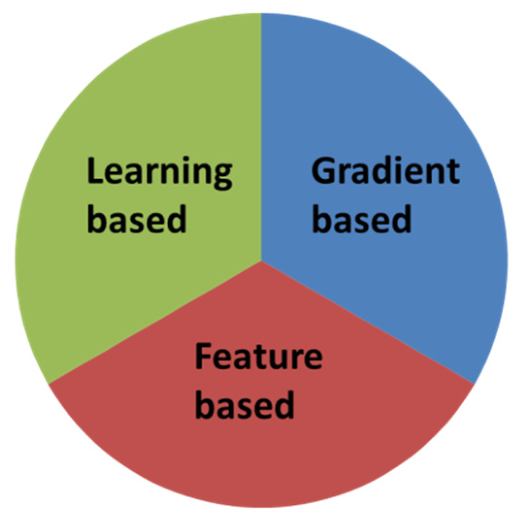
2. Related Work
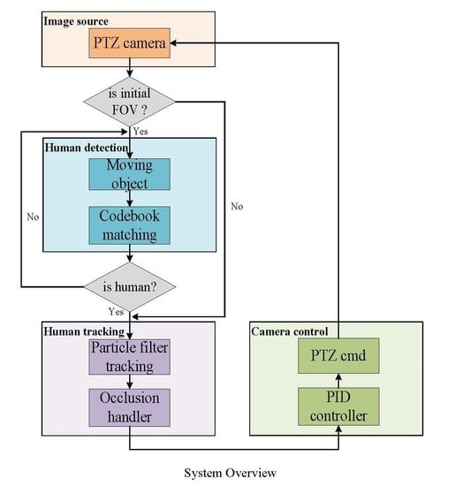
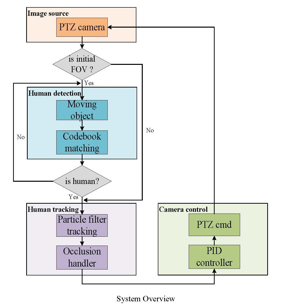
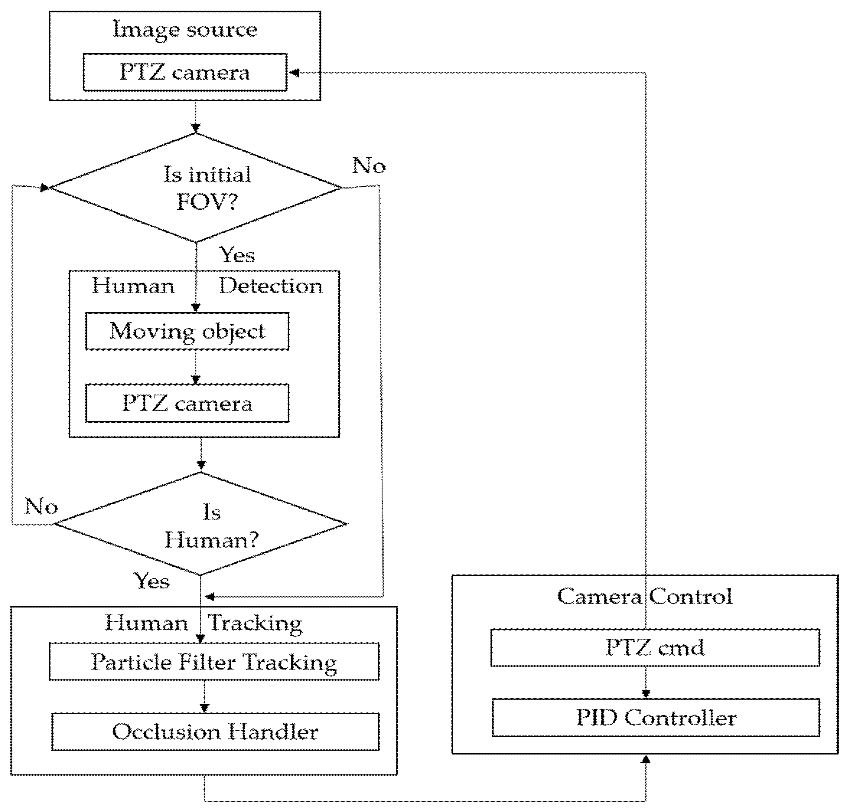
3. Proposed System
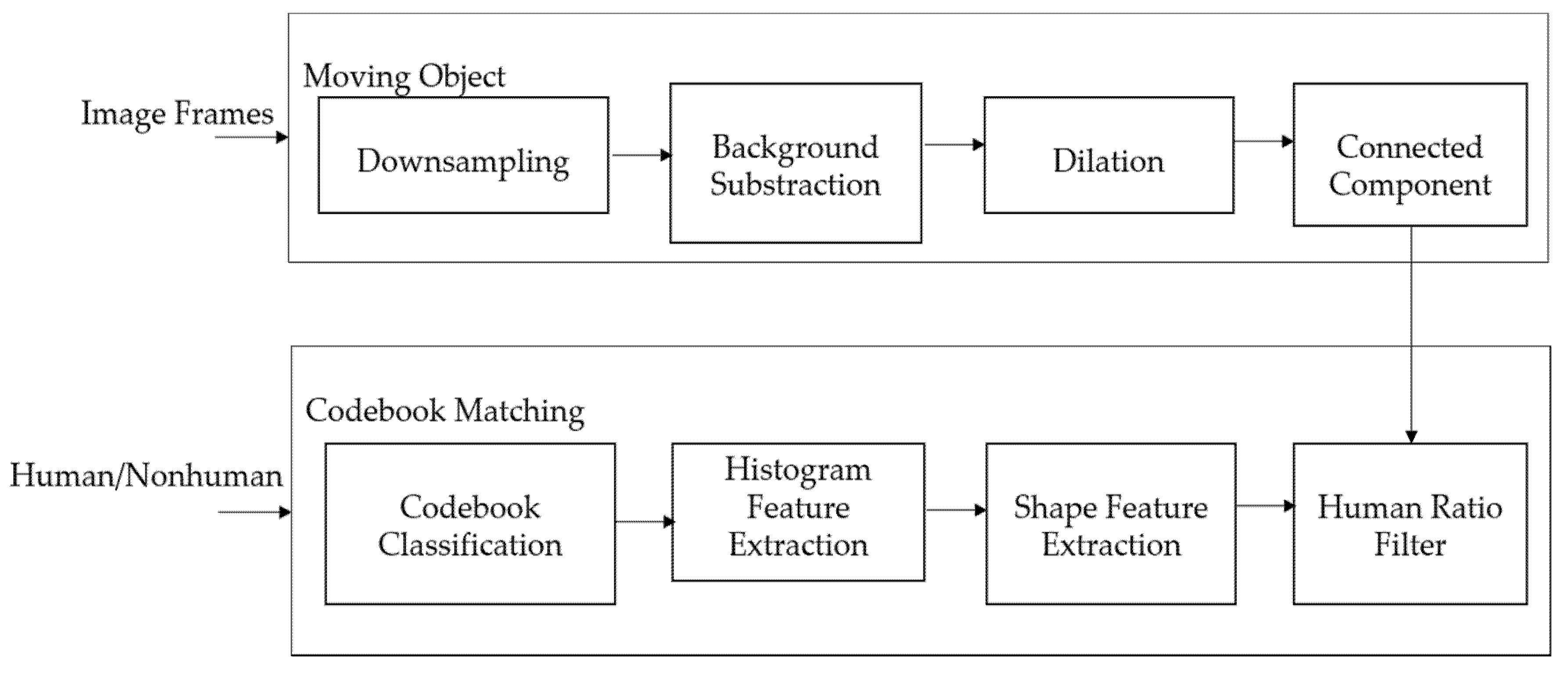
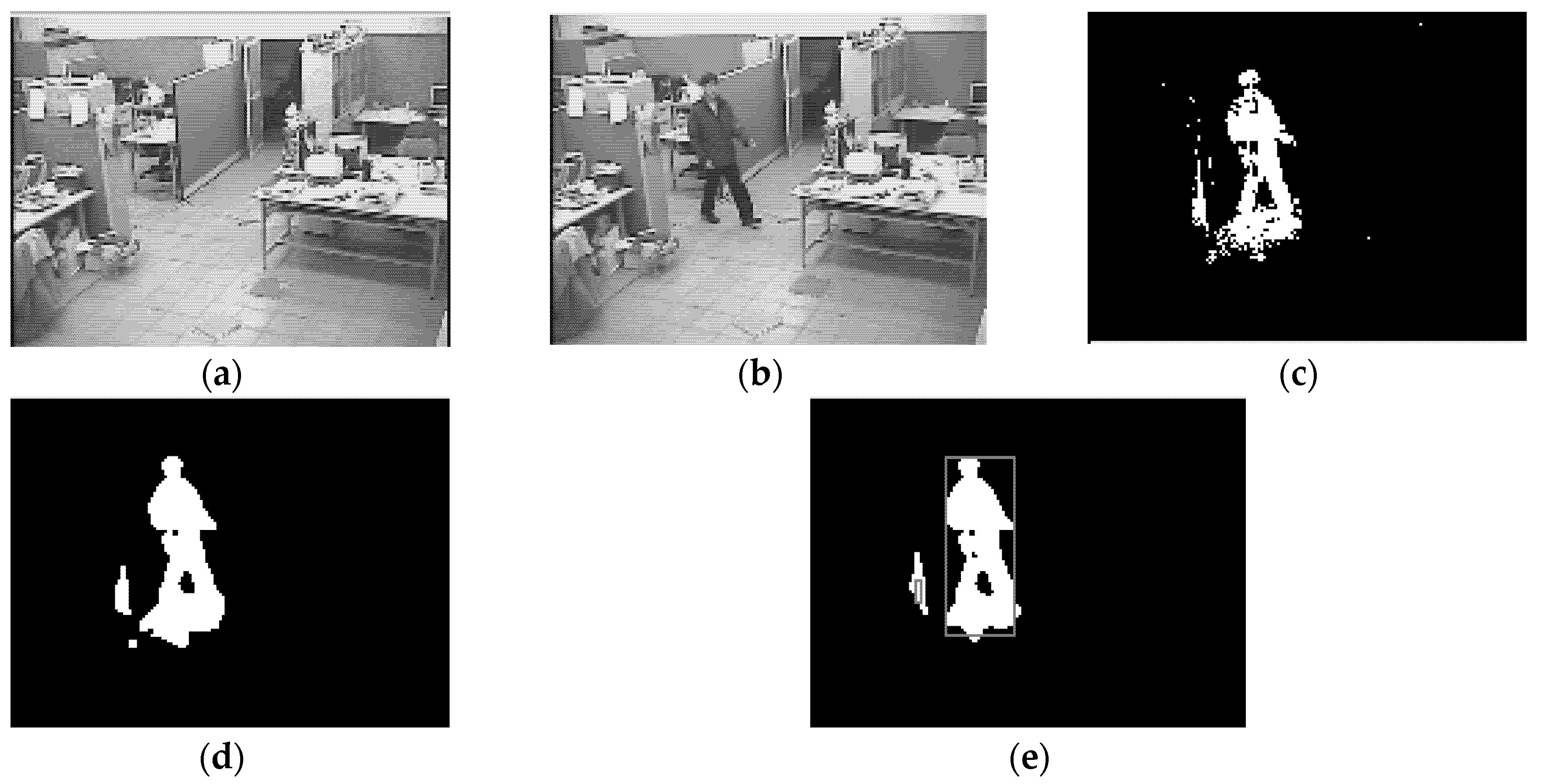
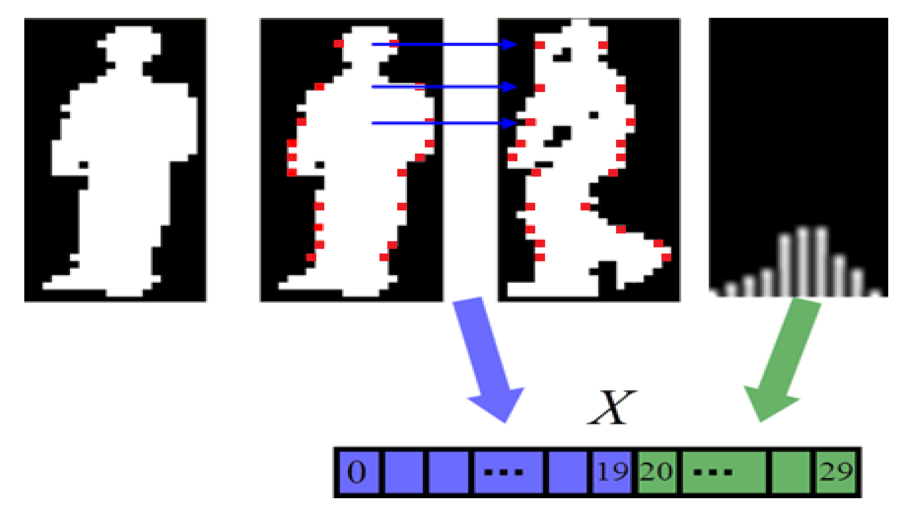
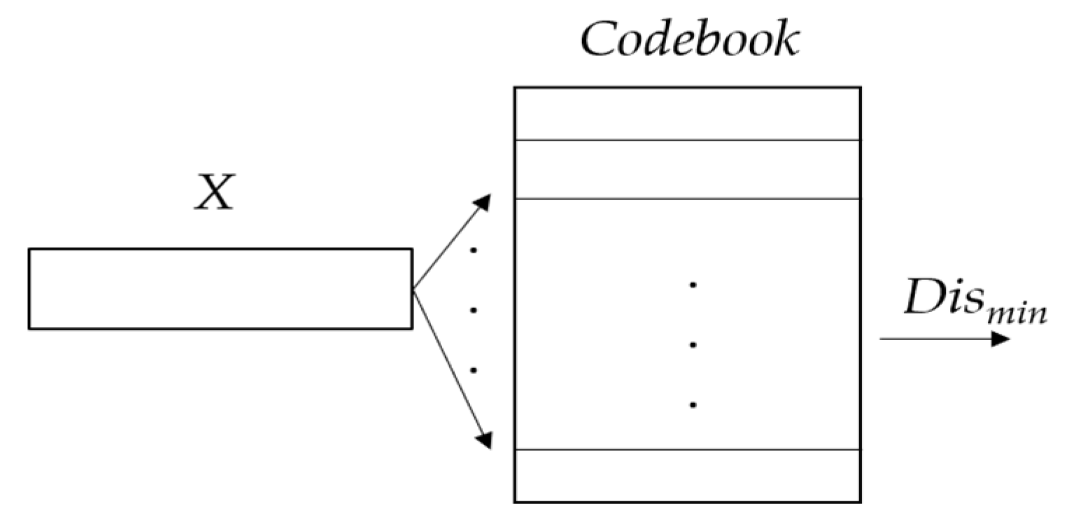
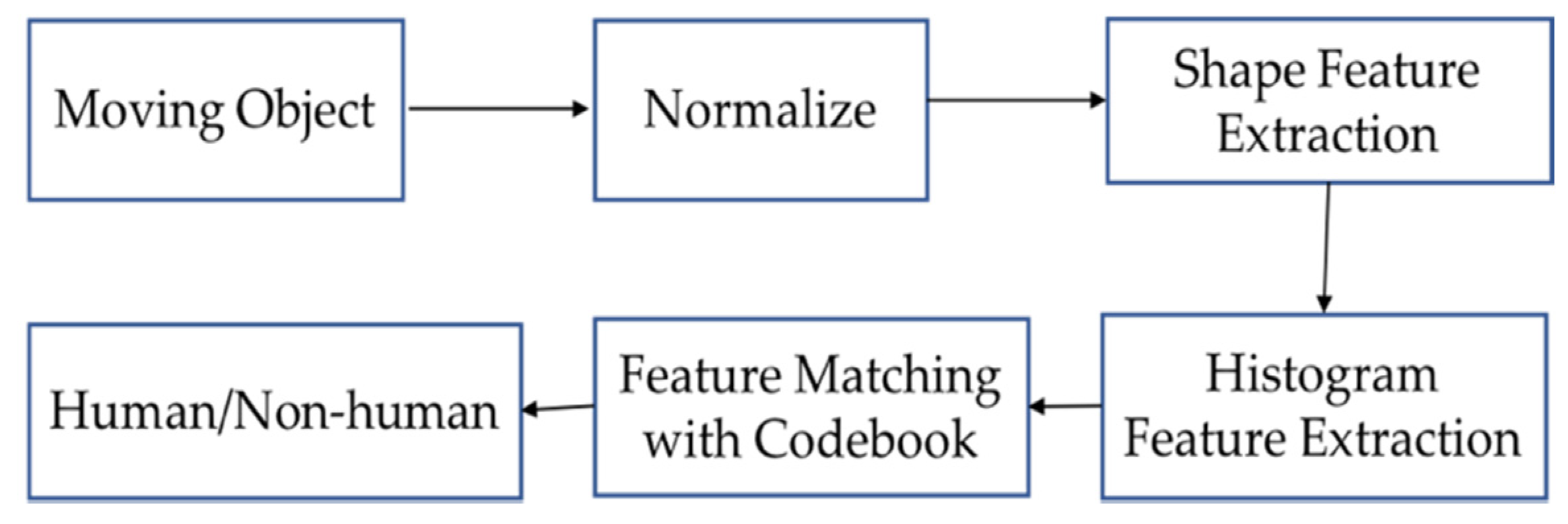
3.1. Human Detection
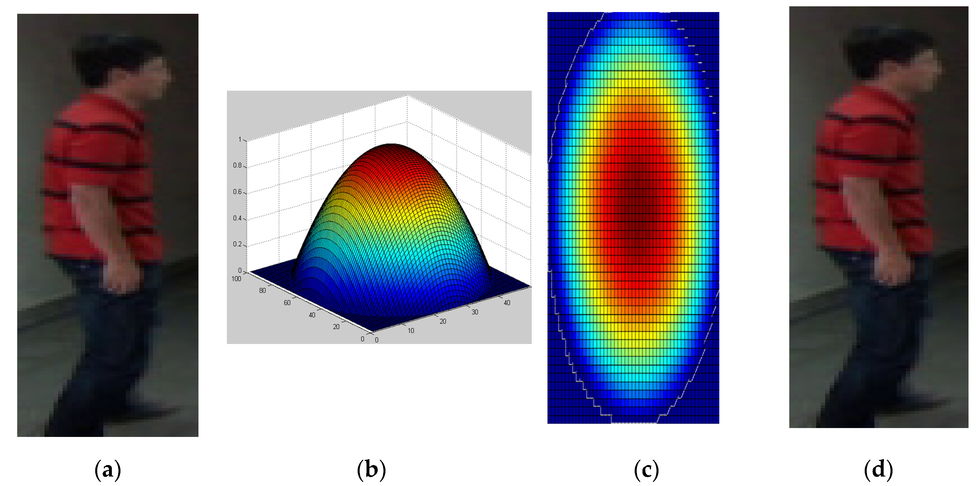
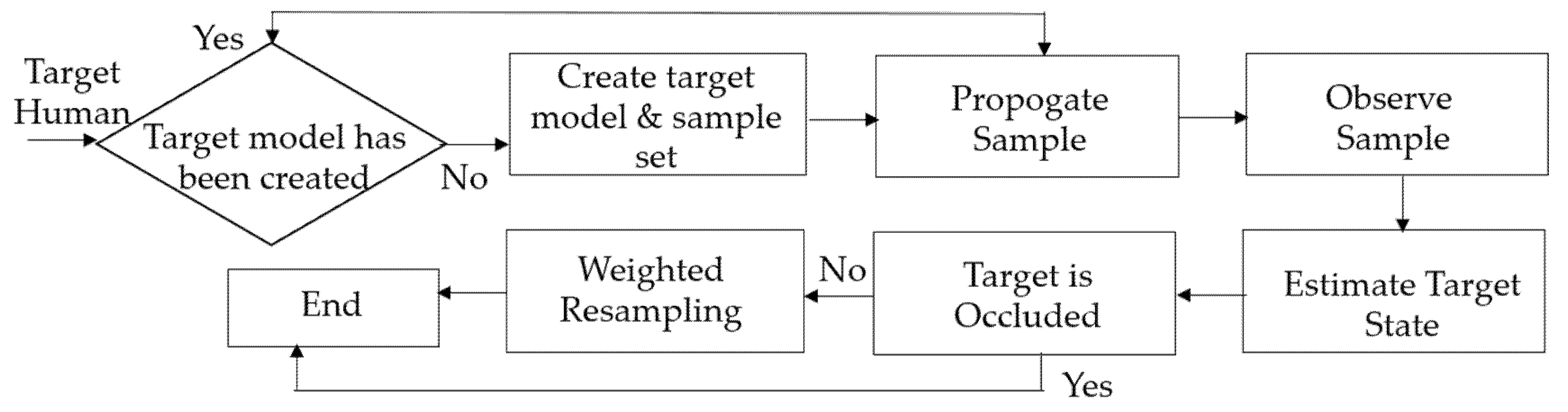
3.2. Human Tracking
- Propagate each sample from the set by a linear stochastic differential equation:
- Observe the color distributions:
- (a)
- Calculate the color distribution: for each sample in the set
- (b)
- Calculate the Bhattacharyya coefficient for each sample of the set :
- (c)
- Weight each sample of the set :
- Estimate the mean state of the set :
- Resample the sample set , if :Select samples from the set with probability :
- (a)
- Calculate the normalized cumulative probabilities :;;
- (b)
- Generate a uniformly distributed random number .
- (c)
- Use binary search to find the smallest for which .
- (d)
- Set .
Finally, resample by .
- We sorted in descending order and obtained the order , .
- We updated the bin’s value using Equation (23) where , , , and , , was the descending order.
- If the difference between the previous and current frames’ was smaller than the threshold, we used Equation (24) to find the first Gaussian distribution where k follows the descending order .
- Candidate model ROI was created in the current frame.
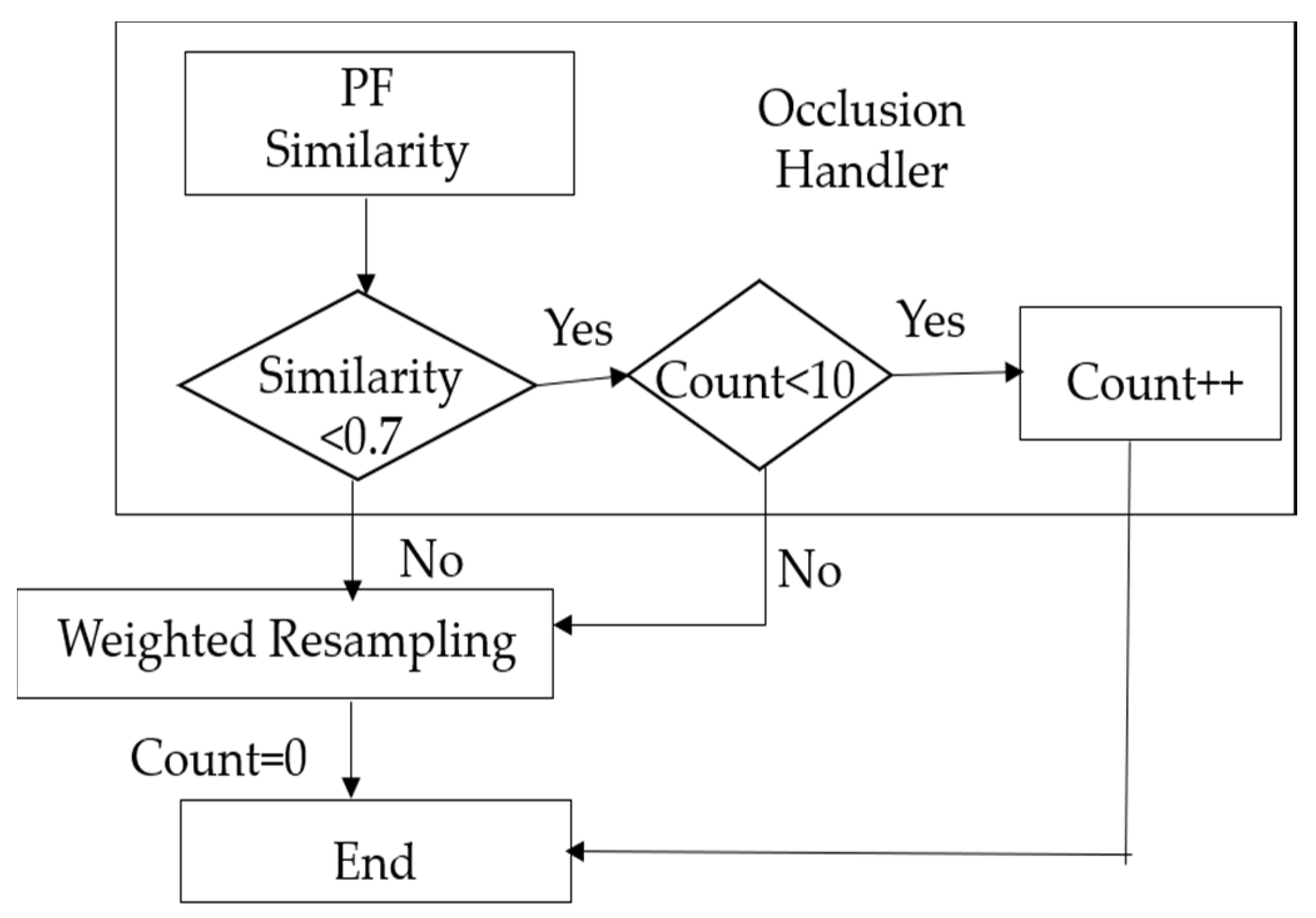
- The similarity value between target model and candidate model was computed.
- If similarity was less than resampling was not performed, and it was assumed that the candidate model was occluded by another object.
- The count was increased using .
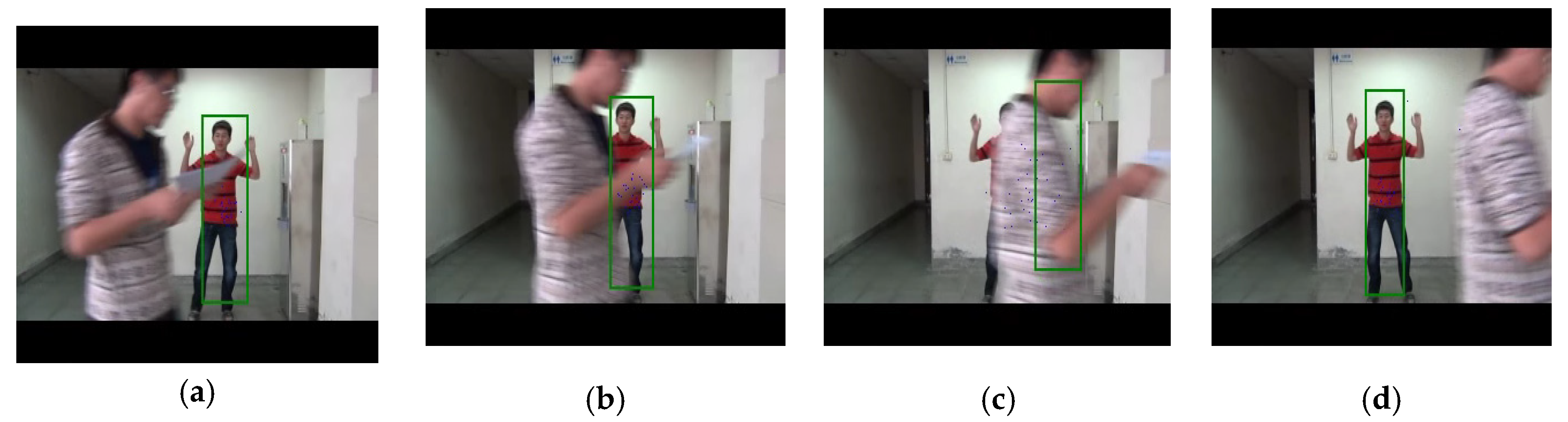
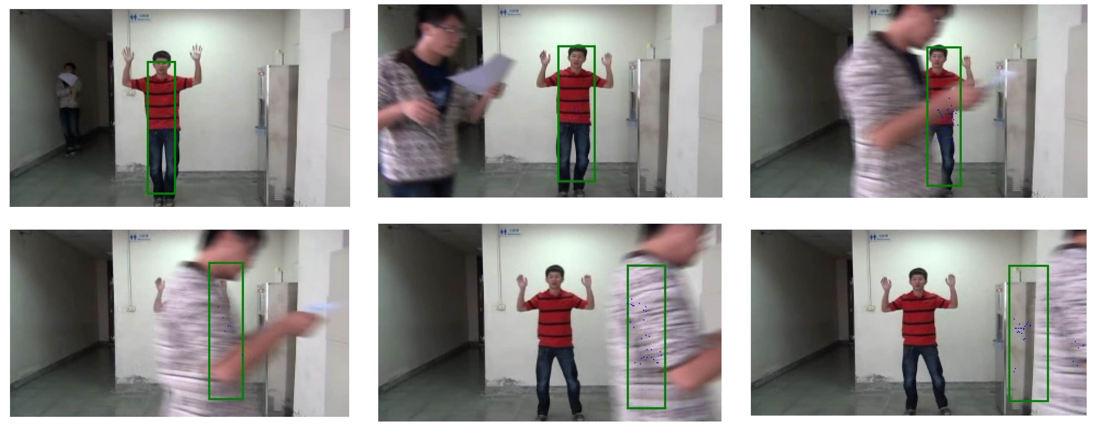
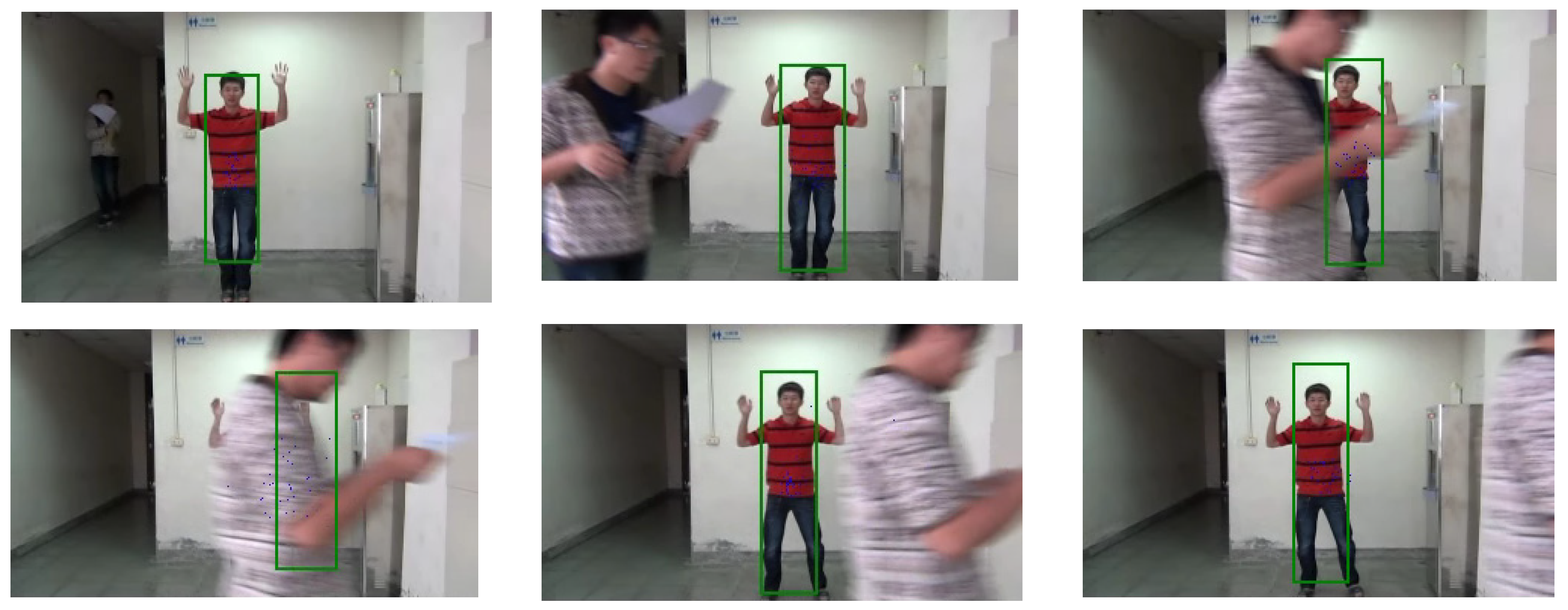
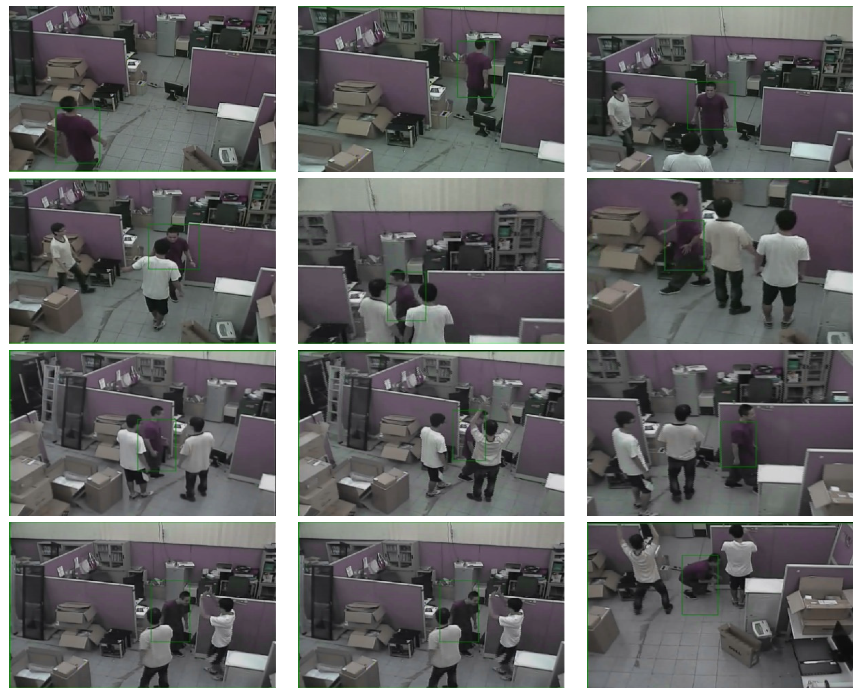
- Step 1–4 were repeated during the tracking process to see whether the similarity value becomes larger than , the tracked human appeared or . Termination condition avoids the spreading of the samples out of the image. Figure 13 shows the images for frame T, T+4, T+9, T+14 using proposed occlusion handler.
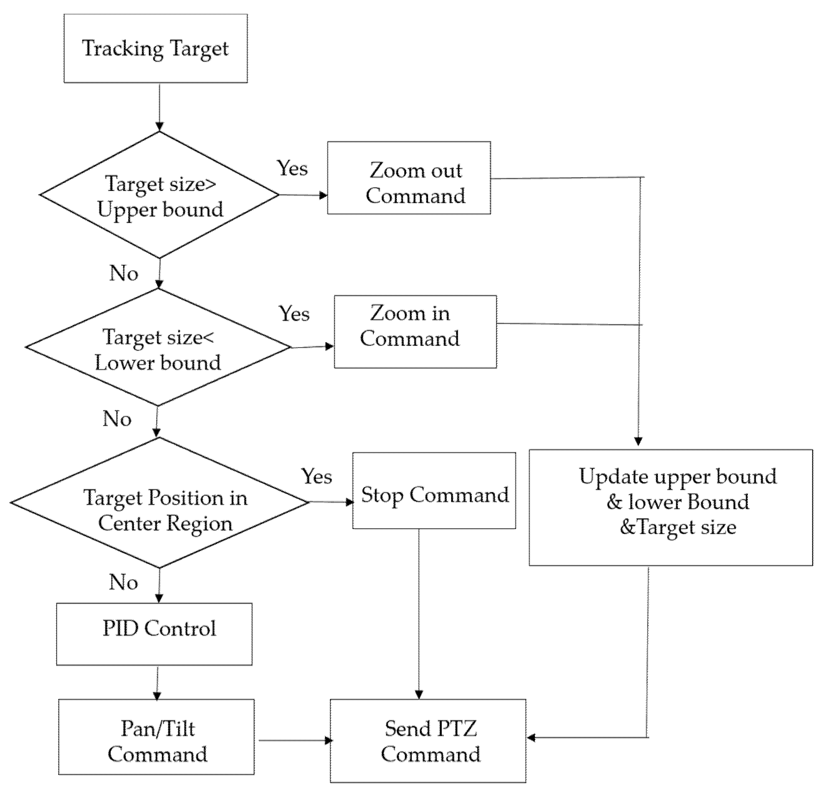
3.3. Camera Control
- Setting value : Central image position.
- Error signal : Difference between the target position and central position.
- Measured value : Tracking system’s estimate of target position.
- Output signal : Output value used to control pan/tilt direction and speed.
4. Experimental Results
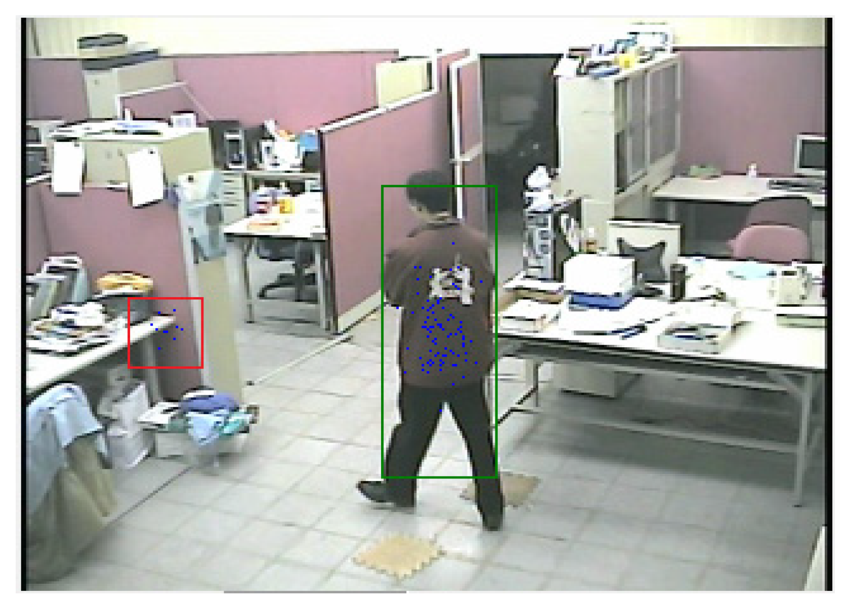
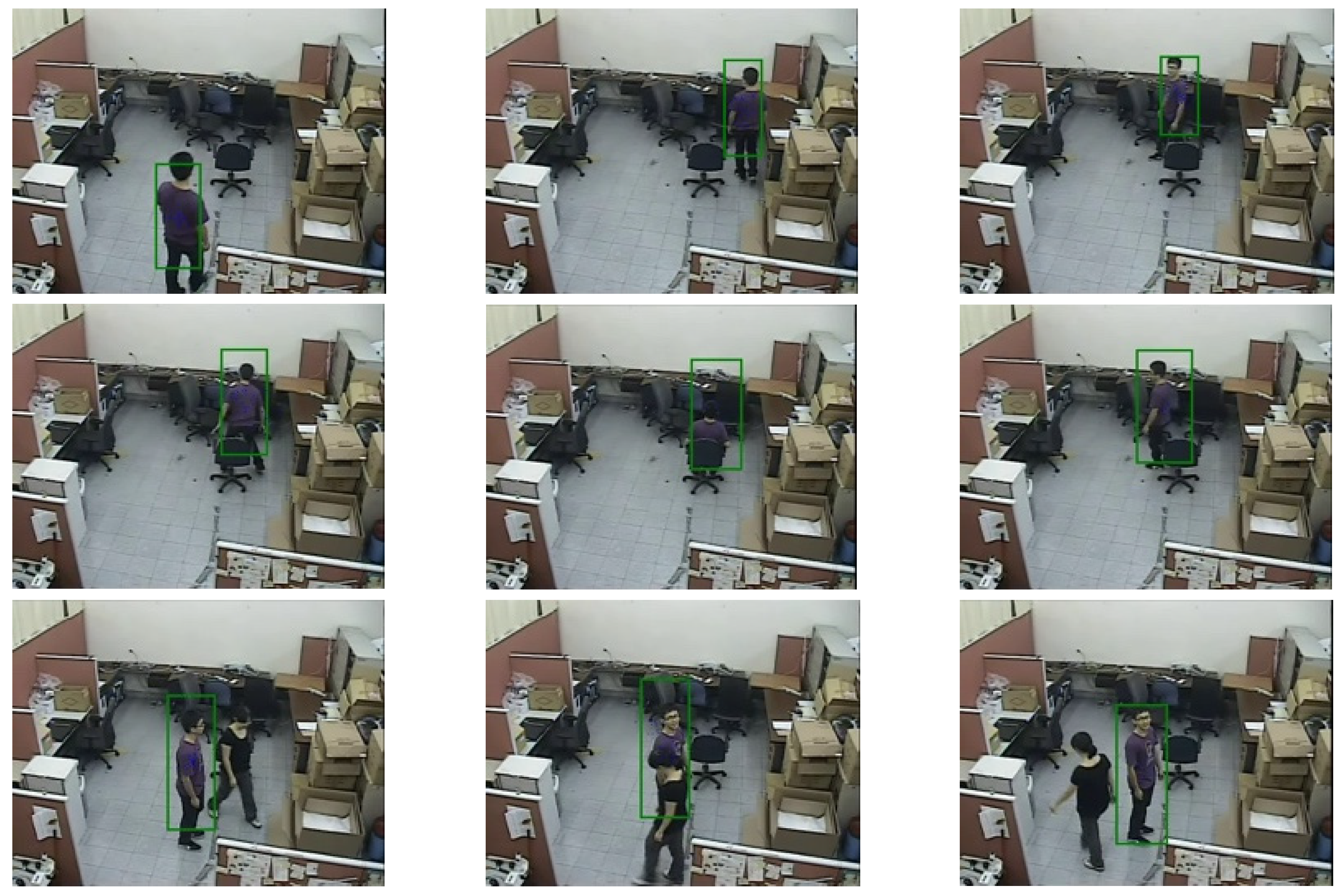
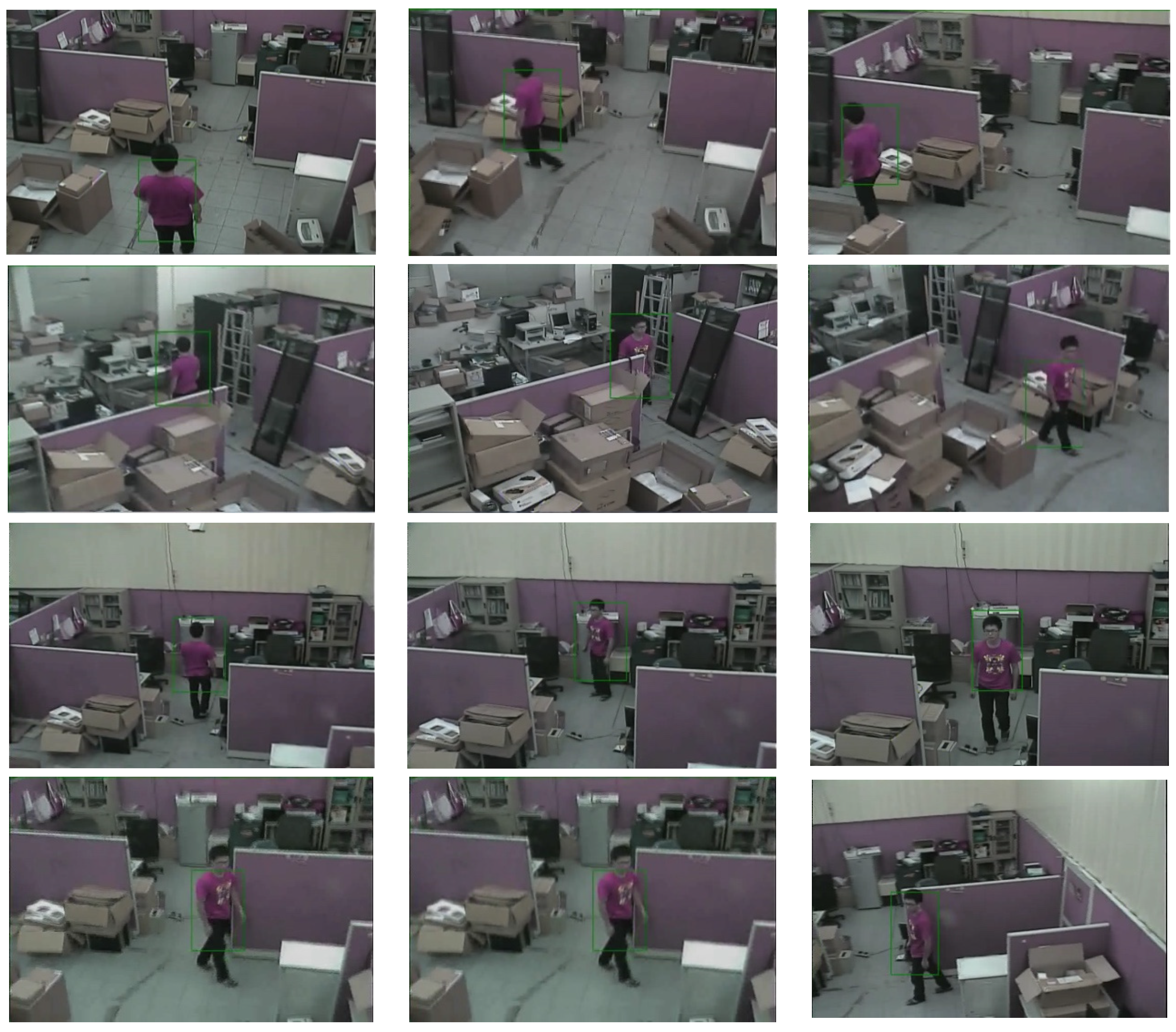
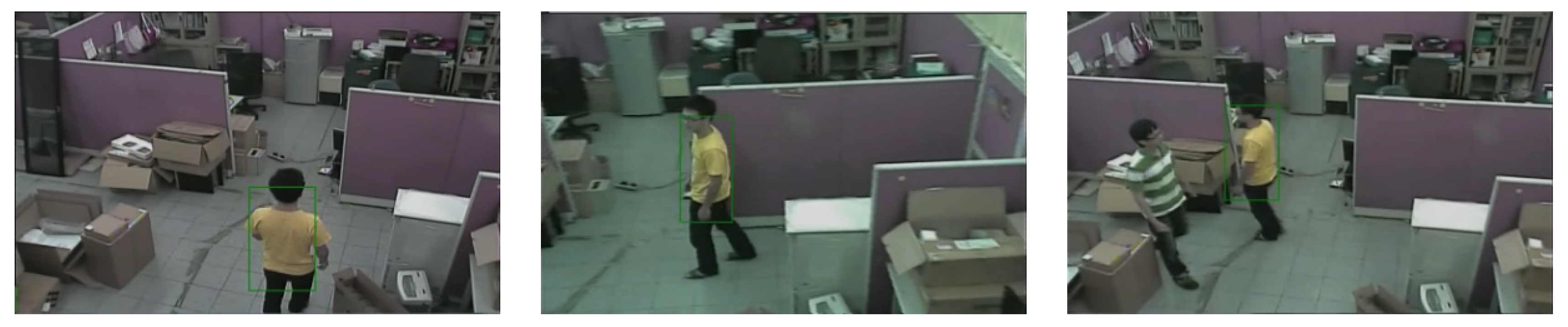
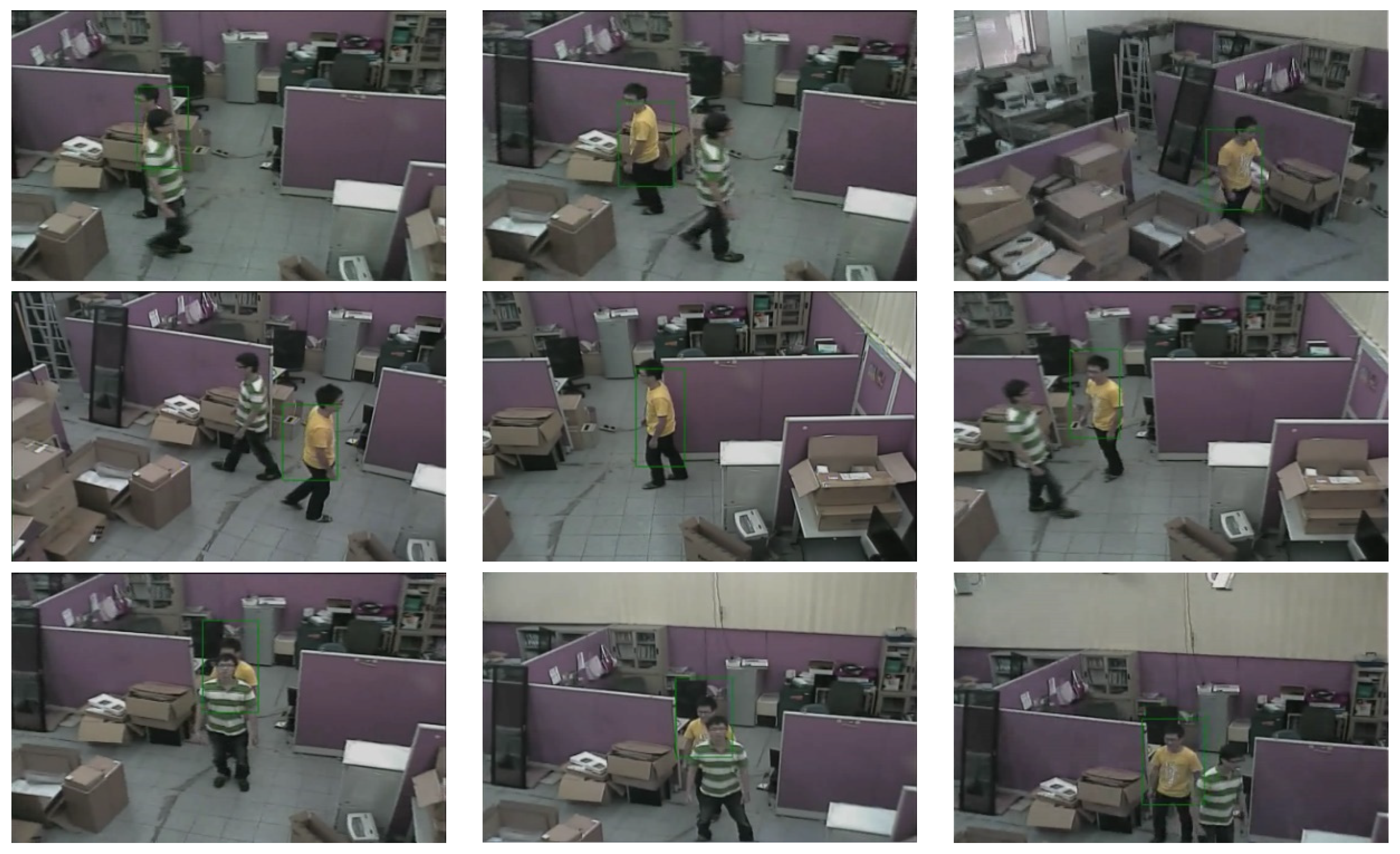
4.1. Results of Tracking on Video File
- Number of bins in histogram
- Number of samples
- State covariance
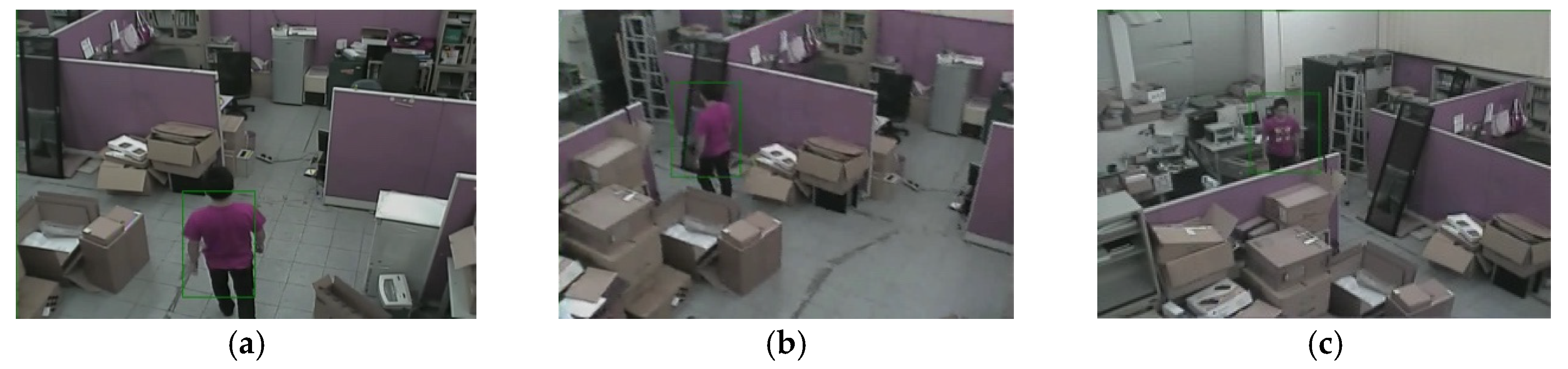
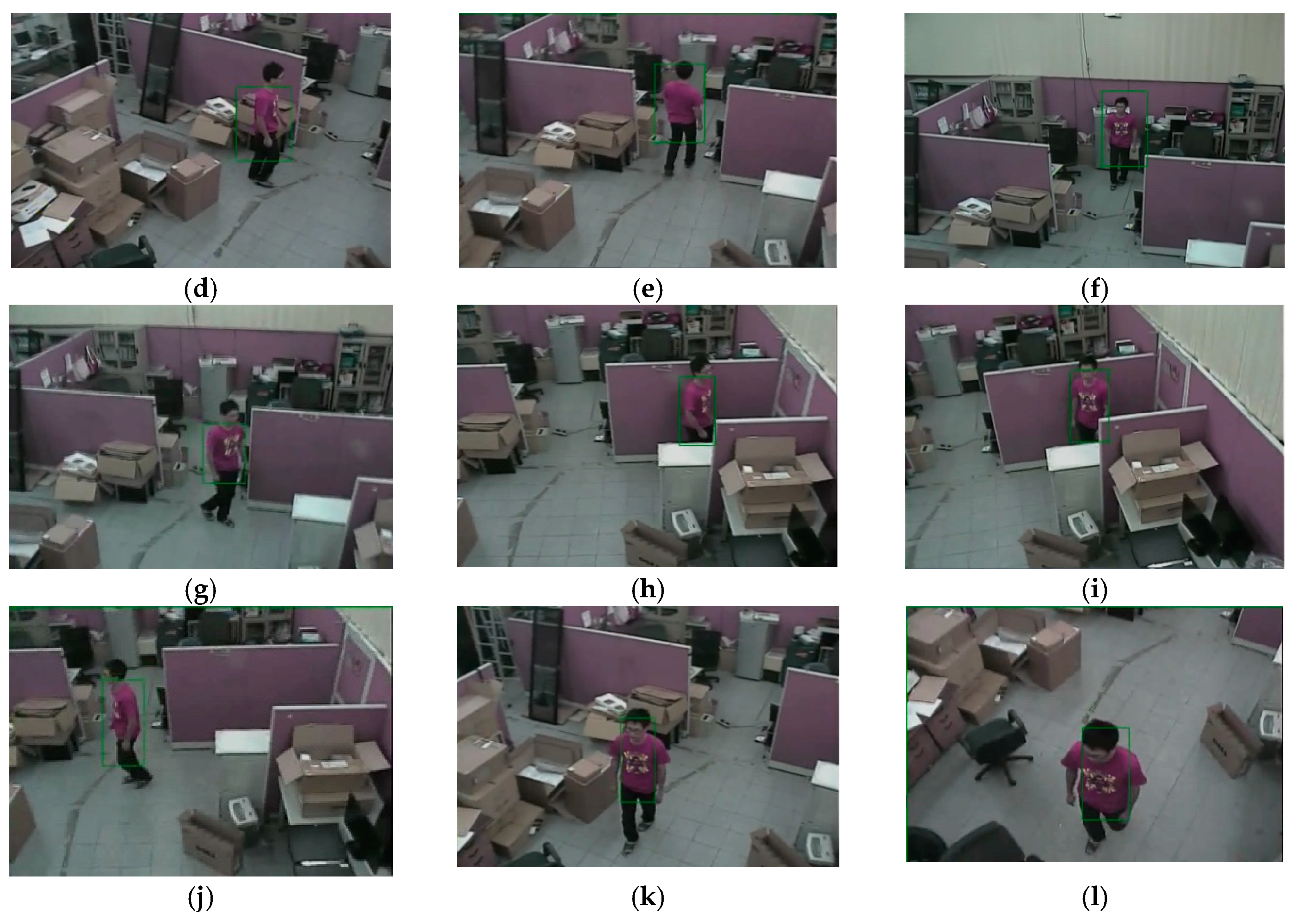
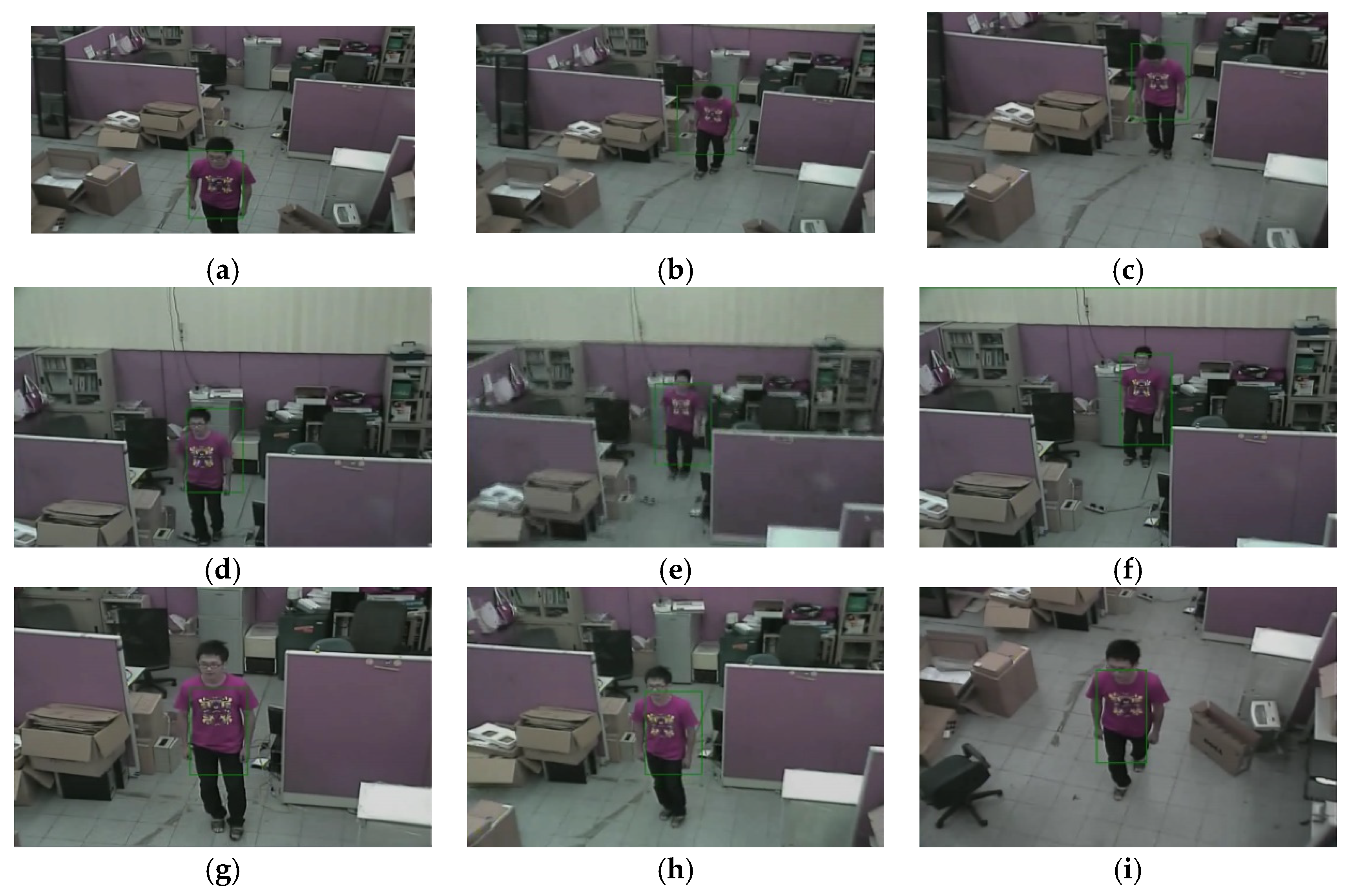
4.2. Results of Tracking on Active Camera Output
- Number of bins in histogram m = 6 × 6 × 6 = 216
- Number of samples N = 30
- State covariance
- Offsetpan = 12
- Offsettilt = 6
- Proportional constant Kp = 0.9
- Integral constant Kt =0.1
- Derivative constant KD = 0.15
- ratebig = 1.1
- ratesmall = 0.9
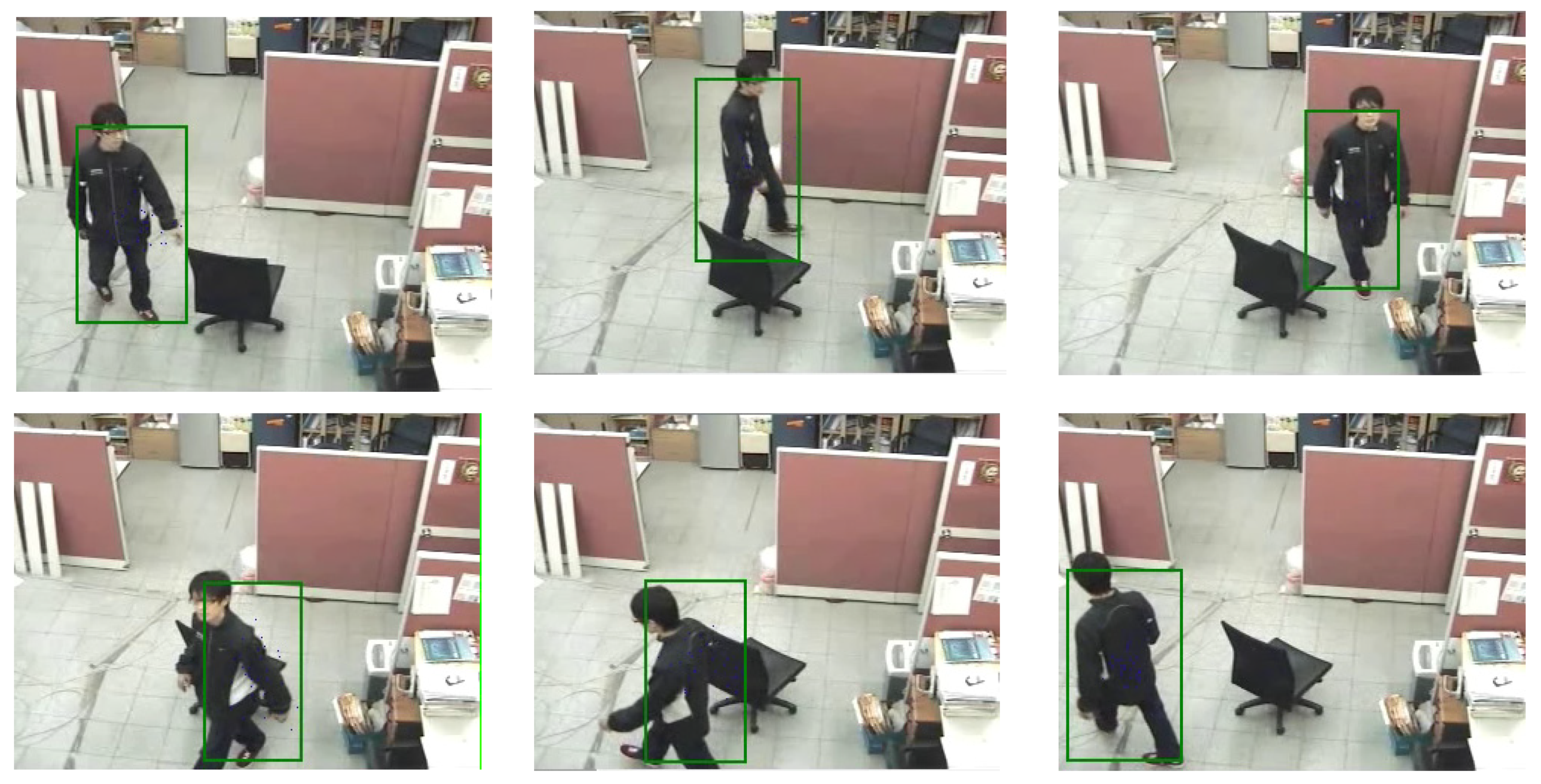
- Our system can accurately distinguish human and nonhuman.
- The weighted resampling can help the particle filter to preserve the samples with high weights.
- The occlusion handler can solve the temporal full occlusion condition.
- It can track the human target smoothly by using the PID controller to determine the motion of camera.
5. Conclusions
Author Contributions
Funding
Conflicts of Interest
References
- Gillner, W.J. Motion based vehicle detection on motorways. In Proceedings of the Intelligent Vehicles ’95 Symposium (IEEE), Detroit, MI, USA, 25–26 September 1995. [Google Scholar]
- Batavia, P.H.; Pomerleau, D.A.; Thorpe, C.E. Overtaking vehicle detection using implicit optical flow. Comput. Stand. Interfaces 1999, 20, 466. [Google Scholar] [CrossRef] [Green Version]
- Zhao, L.; Thorpe, C.E. Stereo-and neural network-based pedestrian detection. IEEE Trans. Intell. Transp. Syst. 2000, 1, 148–154. [Google Scholar] [CrossRef] [Green Version]
- Viola, P.; Jones, M.; Snow, D. Detecting Pedestrians Using Patterns of Motion and Appearance. Int. J. Comput. Vis. 2005, 63, 153–161. [Google Scholar] [CrossRef]
- Dimitrijevic, M.; Lepetit, V.; Fua, P. Human body pose detection using Bayesian spatio-temporal templates. Comput. Vis. Image Underst. 2006, 104, 127–139. [Google Scholar] [CrossRef] [Green Version]
- Montabone, S.; Soto, Á. Human detection using a mobile platform and novel features derived from a visual saliency mechanism. Image Vis. Comput. 2010, 28, 391–402. [Google Scholar] [CrossRef]
- Pang, Y.; Yuan, Y.; Li, X.; Pan, J. Efficient HOG human detection. Signal Process. 2011, 91, 773–781. [Google Scholar] [CrossRef]
- Gonzalez, R.C.; Woods, R.E. Digital Image Processing; Addison-Wesley: New York, NY, USA, 1992. [Google Scholar]
- Marr, D.; Hildreth, E. Theory of edge detection. Proc. R. Soc. London. Ser. B Boil. Sci. 1980, 207, 187–217. [Google Scholar] [CrossRef]
- Li, R.; Tian, T.-P.; Sclaroff, S.; Yang, M.-H. 3D Human Motion Tracking with a Coordinated Mixture of Factor Analyzers. Int. J. Comput. Vis. 2009, 87, 170–190. [Google Scholar] [CrossRef] [Green Version]
- Lopes, N.V.; Couto, P.A.; Jurio, A.; Melo-Pinto, P. Hierarchical fuzzy logic based approach for object tracking. Knowl. -Based Syst. 2013, 54, 255–268. [Google Scholar] [CrossRef] [Green Version]
- Williams, O.; Blake, A.; Cipolla, R. Sparse Bayesian learning for efficient visual tracking. IEEE Trans. Pattern Anal. Mach. Intell. 2005, 27, 1292–1304. [Google Scholar] [CrossRef]
- Collins, R.T.; Liu, Y.; Leordeanu, M. Online selection of discriminative tracking features. IEEE Trans. Pattern Anal. Mach. Intell. 2005, 27, 1631–1643. [Google Scholar] [CrossRef] [PubMed]
- Zhang, W.; Shang, L.; Chan, A.B. A Robust Likelihood Function for 3D Human Pose Tracking. IEEE Trans. Image Process. 2014, 23, 5374–5389. [Google Scholar] [CrossRef] [PubMed]
- Zhao, H.; Xiang, K.; Cao, S.; Wang, X.-Y. Random walks colour histogram modification for human tracking. IET Comput. Vis. 2016, 10, 842–851. [Google Scholar] [CrossRef]
- Fukunaga, K.; Hostetler, L. The estimation of the gradient of a density function, with applications in pattern recognition. IEEE Trans. Inf. Theory 1975, 21, 32–40. [Google Scholar] [CrossRef] [Green Version]
- Comaniciu, D.; Ramesh, V.; Meer, P. Kernel-based object tracking. IEEE Trans. Pattern Anal. Mach. Intell. 2003, 25, 564–577. [Google Scholar] [CrossRef] [Green Version]
- Wang, L.; Yan, H.; Wu, H.-Y.; Pan, C. Forward–Backward Mean-Shift for Visual Tracking With Local-Background-Weighted Histogram. IEEE Trans. Intell. Transp. Syst. 2013, 14, 1480–1489. [Google Scholar] [CrossRef]
- Vojir, T.; Noskova, J.; Matas, J. Robust scale-adaptive mean-shift for tracking. Pattern Recognit. Lett. 2014, 49, 250–258. [Google Scholar] [CrossRef]
- Vella, F.; Infantino, I.; Scardino, G. Person identification through entropy oriented mean shift clustering of human gaze patterns. Multimedia Tools Appl. 2016, 76, 2289–2313. [Google Scholar] [CrossRef]
- Liu, J.; Zhong, X. An object tracking method based on Mean Shift algorithm with HSV color space and texture features. Clust. Comput. 2018, 22, 6079–6090. [Google Scholar] [CrossRef]
- Ali, A.; Jalil, A.; Ahmed, J.; Iftikhar, M.A.; Hussain, M. Correlation, Kalman filter and adaptive fast mean shift based heuristic approach for robust visual tracking. Signal Image Video Process. 2014, 9, 1567–1585. [Google Scholar] [CrossRef]
- Jeong, J.; Yoon, T.S.; Park, J.B. Mean shift tracker combined with online learning-based detector and Kalman filtering for real-time tracking. Expert Syst. Appl. 2017, 79, 194–206. [Google Scholar] [CrossRef]
- Bhat, P.G.; Subudhi, B.N.; Veerakumar, T.; Laxmi, V.; Gaur, M.S. Multi-Feature Fusion in Particle Filter Framework for Visual Tracking. IEEE Sens. J. 2020, 20, 2405–2415. [Google Scholar] [CrossRef]
- Nummiaro, K.; Koller-Meier, E.; Van Gool, L. An adaptive color-based particle filter. Image Vis. Comput. 2003, 21, 99–110. [Google Scholar] [CrossRef]
- Alcantarilla, P.F.; Bartoli, A.; Davison, A.J. KAZE features. In European Conference on Computer Vision; Springer: Berlin/Heidelberg, Germany, 2012; pp. 214–227. [Google Scholar]
- Murray, D.; Basu, A. Motion tracking with an active camera. IEEE Trans. Pattern Anal. Mach. Intell. 1994, 16, 449–459. [Google Scholar] [CrossRef] [Green Version]
- Karamiani, A.; Farajzadeh, N. Optimal feature points for tracking multiple moving objects in active camera model. Multimedia Tools Appl. 2015, 75, 10999–11017. [Google Scholar] [CrossRef]
- Lisanti, G.; Masi, I.; Pernici, F.; Del Bimbo, A. Continuous localization and mapping of a pan–tilt–zoom camera for wide area tracking. Mach. Vis. Appl. 2016, 27, 1071–1085. [Google Scholar] [CrossRef] [Green Version]
- Mathivanan, A.; Palaniswamy, S. Efficient fuzzy feature matching and optimal feature points for multiple objects tracking in fixed and active camera models. Multimed. Tools Appl. 2019, 78, 27245–27270. [Google Scholar] [CrossRef]
- Fan, J.; Xu, W.; Wu, Y.; Gong, Y. Human tracking using convolutional neural networks. IEEE Trans. Neural Netw. 2010, 21, 1610–1623. [Google Scholar] [PubMed]
- Tyan, V.; Kim, D. Convolutional Neural Network with Particle Filter Approach for Visual Tracking. KSII Trans. Internet Inf. Syst. 2018, 12, 693–709. [Google Scholar] [CrossRef]
- Ren, Z.; Yang, S.; Zou, F.; Yang, F.; Luan, C.; Li, K. A face tracking framework based on convolutional neural networks and Kalman filter. In Proceedings of the 8th IEEE International Conference on Software Engineering and Service Science (ICSESS), Beijing, China, 24–26 November 2017. [Google Scholar]
- Angelico, J.; Wardani, K.R.R. Convolutional neural network using kalman filter for human detection and tracking on RGB-D video CommIT. Commun. Inform. Technol. J. 2018, 12, 105–110. [Google Scholar]
- Luo, Y.; Yin, D.; Wang, A.; Wu, W. Pedestrian tracking in surveillance video based on modified CNN. Multimed. Tools Appl. 2018, 77, 24041–24058. [Google Scholar] [CrossRef]
- Xia, Y.; Qu, S.; Goudos, S.; Bai, Y.; Wan, S. Multi-object tracking by mutual supervision of CNN and particle filter. Pers. Ubiquitous Comput. 2019, 1–10. [Google Scholar] [CrossRef]
- Choe, G.; Choe, C.; Wang, T.; So, H.; Nam, C.; Yuan, C. Deep learning with particle filter for person re-identification. Multimed. Tools Appl. 2018, 78, 6607–6636. [Google Scholar] [CrossRef]
- Aslan, M.F.; Durdu, A.; Sabanci, K.; Mutluer, M.A. CNN and HOG based comparison study for complete occlusion handling in human tracking. Measurment 2020, 158, 107704. [Google Scholar] [CrossRef]
- Stauffer, C.; Grimson, W. Adaptive background mixture models for real-time tracking. In Proceedings of the 1999 IEEE Computer Society Conference on Computer Vision and Pattern Recognition, Fort Collins, CO, USA, 23–25 June 1999. [Google Scholar]
- Salazar, A.; Igual, J.; Safont, G.; Vergara, L.; Vidal, A. Image Applications of Agglomerative Clustering Using Mixtures of Non-Gaussian Distributions. In Proceedings of the 2015 International Conference on Computational Science and Computational Intelligence (CSCI), Washington, DC, USA, 7–9 December 2015. [Google Scholar]


| Bit 7 | Bit 6 | Bit 5 | Bit 4 | Bit 3 | Bit 2 | Bit 1 | Bit 0 | |
|---|---|---|---|---|---|---|---|---|
| Data byte 1 | Fixed to 0 | Camera On | Auto Scan On | Camera On/Off | Iris Close | Iris Open | Focus Near | Focus Far |
| Data byte 2 | Fixed to 0 | Zoom Wide | Zoom Tele | Tilt Down | Tilt Up | Pan Left | Pan Right | 0 (for pan/tilt) |
| Data byte 3 | Pan speed 00 (stop) to 3F (high speed) and 40 for Turbo | |||||||
| Data byte 4 | Tilt speed 00 (stop) to 3F (high speed) | |||||||
| (a) | (b) | (c) | (d) | (e) | (f) | (g) | (h) | (i) | (j) | (k) | (l) | |
|---|---|---|---|---|---|---|---|---|---|---|---|---|
| 0 | 0 | 1 | 1 | 1 | 0 | 0 | 1 | 2 | 1 | 0 | 0 |
| (a) | (b) | (c) | (d) | (e) | (f) | (g) | (h) | (i) | |
|---|---|---|---|---|---|---|---|---|---|
| 0 | 0 | 1 | 2 | 1 | 2 | 3 | 2 | 1 |
© 2020 by the authors. Licensee MDPI, Basel, Switzerland. This article is an open access article distributed under the terms and conditions of the Creative Commons Attribution (CC BY) license (http://creativecommons.org/licenses/by/4.0/).
Share and Cite
Chang, L.C.; Pare, S.; Meena, M.S.; Jain, D.; Li, D.L.; Saxena, A.; Prasad, M.; Lin, C.T. An Intelligent Automatic Human Detection and Tracking System Based on Weighted Resampling Particle Filtering. Big Data Cogn. Comput. 2020, 4, 27. https://0-doi-org.brum.beds.ac.uk/10.3390/bdcc4040027
Chang LC, Pare S, Meena MS, Jain D, Li DL, Saxena A, Prasad M, Lin CT. An Intelligent Automatic Human Detection and Tracking System Based on Weighted Resampling Particle Filtering. Big Data and Cognitive Computing. 2020; 4(4):27. https://0-doi-org.brum.beds.ac.uk/10.3390/bdcc4040027
Chicago/Turabian StyleChang, Liang Cheng, Shreya Pare, Mahendra Singh Meena, Deepak Jain, Dong Lin Li, Amit Saxena, Mukesh Prasad, and Chin Teng Lin. 2020. "An Intelligent Automatic Human Detection and Tracking System Based on Weighted Resampling Particle Filtering" Big Data and Cognitive Computing 4, no. 4: 27. https://0-doi-org.brum.beds.ac.uk/10.3390/bdcc4040027