
Computational Assessment of Neural Probe and Brain Tissue Interface under Transient Motion

Abstract
:1. Introduction
2. Materials and Methods
3. Results
4. Discussion
5. Conclusions
Acknowledgments
Author Contributions
Conflicts of Interest
References
- Wise, K.D.; Angell, J.B.; Starr, A. An integrated-circuit approach to extra cellular microelectrodes. IEEE Trans. Biomed. Eng. 1970, 17, 238–247. [Google Scholar] [CrossRef] [PubMed]
- Campbell, P.K.; Jones, K.E.; Huber, R.J.; Horch, K.W.; Normann, R.A. A silicon-based, three-dimensional neural interface: Manufacturing processes for an intercortical electrode array. IEEE Trans. Biomed. Eng. 1991, 38, 758–768. [Google Scholar] [CrossRef] [PubMed]
- Donoghue, J.P. Connecting cortex to machines: Recent advances in brain interfaces. Nat. Neuroscience. 2002, 5, 1085–1088. [Google Scholar] [CrossRef] [PubMed]
- Lebedev, M.A.; Nicolelis, M.A.L. Brain-machine interfaces: Past, present and future. Trends Neurosci. 2006, 29, 536–546. [Google Scholar] [CrossRef] [PubMed]
- Zhang, J.; Atay, T.; Nurmikko, A.V. Optical detection of brain cell activity using plasmonic gold nanoparticles. Nano Lett. 2009, 9, 519–524. [Google Scholar] [CrossRef] [PubMed]
- Kneipp, K.; Moskovits, M.; Kneipp, H. Surface-enhanced Raman scattering: Physics and applications. In Topics in Applied Physics; Springer: Berlin, Germany, 2006; pp. 47–66. [Google Scholar]
- Wang, J.; Wagner, F.; Borton, D.A.; Zhang, J.; Ozden, I.; Burwell, R.D.; Nurmikko, A.; van Wagenen, R.; Diester, I.; Deisseroth, K. Integrated device for combined optical neuromodulation and electrical recording for chronic in vivo applications. J. Neural Eng. 2012, 9, 16001–16014. [Google Scholar] [CrossRef] [PubMed]
- Tidswell, T.; Gibson, A.; Bayford, R.H.; Holder, D.S. Three-dimensional electrical impedance tomography of human brain activity. Neuroimage 2001, 13, 283–294. [Google Scholar] [CrossRef] [PubMed]
- Yoon, H.; Hankins, P.; Oh, S.; Haubaugh, R.E.; Varadan, V.K. Heterostructured IrO2/Au nanowire electrodes and unit recordings from hippocampal rat brain. J. Nanotech. Eng. Med. 2010, 1. [Google Scholar] [CrossRef]
- Polikov, V.S.; Tresco, P.A.; Reichert, W.M. Response of brain tissue to chronically implanted neural electrodes. J. Neurosci. Meth. 2005, 148, 1–18. [Google Scholar] [CrossRef] [PubMed]
- Xie, Y.; Martini, N.; Hassler, C.; Kirch, R.K.; Stieglitz, T.; Seifert, A.; Hofmann, U.G. In vivo monitoring of glial scar proliferation on chronically implanted neural electrodes by fiber optical coherence tomography. Front. Neuroeng. 2014, 7. [Google Scholar] [CrossRef] [PubMed]
- Kozai, T.D.; Catt, K.; Li, X.; Gugel, Z.V.; Olafsson, V.T.; Vasquez, A.L.; Cui, X.T. Mechanical failure modes of chronically implanted planar silicon-based neural probes for laminar recording. Biomaterials 2015, 37, 25–39. [Google Scholar] [CrossRef] [PubMed]
- Rosenzweig, J.M.; Lei, J.; Burd, I. Interleukin-1 receptor blockade in perinatal brain injury. Front. Pediatr. 2014, 2. [Google Scholar] [CrossRef] [PubMed]
- Kozai, T.D.; Li, X.; Bodily, L.M.; Caparosa, E.M.; Zenonos, G.A.; Carlisle, D.L.; Friedlander, R.M.; Cui, X.T. Effects of caspase-1 knockout on chronic neural recording quality and longetivity: Insight into cellular and molecular mechanisms of the reactive tissue response. Biomaterials 2014, 35, 9620–9624. [Google Scholar] [CrossRef] [PubMed]
- Misra, A.; Kondaveeti, P.; Nissanov, J.; Barbee, K.; Shewokis, P.; Rioux, L.; Moxon, K.A. Preventing neuronal damage and inflammation in vivo during cortical microelectrode implantation through the use of poloxamer P-188. J. Neural Eng. 2013, 10. [Google Scholar] [CrossRef] [PubMed]
- Gutowski, S.M.; Shoemaker, J.T.; Templeman, K.L.; Wei, Y.; Latour, R.A.; Bellamkonda, R.V.; LaPlaca, M.C.; Garcia, A.J. Protese-degradable PEG-maleimide coating with on-demand release of IL-1Ra to improve tissue response to neural electrodes. Biomaterials 2015, 44, 55–70. [Google Scholar] [CrossRef] [PubMed]
- Lee, H.J.; Son, Y.; Kim, J.; Lee, C.J.; Yoon, E.-S.; Cho, I.-J. A multichannel neural probe with embedded microfluidic channels for simultaneous in vivo neural recording and drug delivery. Lab Chip 2015, 15, 1590–1597. [Google Scholar] [CrossRef] [PubMed]
- Altuna, A.; Berzango, J.; Fernandez, L.J. Polymer SU-8-based microprobes for neural recording and drug delivery. Front. Mater. 2015, 2, 2. [Google Scholar] [CrossRef]
- Jeong, J.W.; McCall, J.G.; Zhang, Y.; Huang, Y. Soft microfluidic neural probes for wireless drug delivery in freely behaving mice. In Proceedings of the 18th International Conference on Solid State Sensors, Actuators, and Microsystems, Anchorage, AK, USA, 21–25 June 2015; pp. 2264–2267.
- HajjHassan, M.; Chodavarapu, V.; Musallam, S. NeuroMEMS: Neural probe microtechnologies. Sensors 2008, 8, 6704–6726. [Google Scholar] [CrossRef]
- Motta, P.S.; Judy, J.W. Multielectrode microprobes for deep-brain stimulation fabricated with a customizable 3-D electroplating process. IEEE Trans. Biomed. Eng. 2005, 52, 923–933. [Google Scholar] [CrossRef] [PubMed]
- Mercanzini, A.; Cheung, K.; Buhl, D.; Boers, M.; Maillard, A.; Colin, P.; Bensadoun, J.; Bertsch, A.; Carleton, A.; Renaud, P. Demonstration of cortical recording and reduced inflammatory response using flexible polymer neural probes. In Proceedings of the IEEE MEMS Conference, Kobe, Japan, 21–25 January 2007; pp. 573–576.
- Rousche, P.J.; Pellinen, D.S.; Pivin, D.P., Jr.; Williams, J.C.; Kipke, D.R. Flexible polyimide-based intracortical electrode arrays with bioactive capability. IEEE Trans. Biomed. Eng. 2001, 48, 361–371. [Google Scholar] [CrossRef] [PubMed]
- Cheung, K.C.; Renaud, P.; Tanila, H.; Djupsund, K. Flexible polyimide microelectrode array for in vivo recordings and current source density analysis. Biosens. Bioelectron. 2007, 22, 1783–1790. [Google Scholar] [CrossRef] [PubMed]
- Edell, D.J.; Toi, V.V.; McNeil, V.M.; Clark, L.D. Factors influencing the biocompatibility of insertable silicon microshafts in cerebral cortex. IEEE Trans. Biomed. Eng. 1992, 39, 635–643. [Google Scholar] [CrossRef] [PubMed]
- Kim, D.H.; Abidian, M.; Martin, D.C. Conducting polymers grown in hydrogel scaffolds coated on neural prosthetic devices. J. Biomed. Mater. Res. A 2004, 71, 577–585. [Google Scholar] [CrossRef] [PubMed]
- Kozai, T.D.; Kipke, D.R. Insertion shuttle with carboxyl terminated self-assembled monolayer coatings for implanting flexible polymer neural probes in the brain. J. Neurosci. Methods 2009, 184, 199–205. [Google Scholar] [CrossRef] [PubMed]
- Felix, S.H.; Shah, K.G.; Tolosa, V.M.; Sheth, H.J.; Tooker, A.C.; Delima, T.L.; Jadhay, S.P.; Frank, L.M.; Pannu, S.S. Insertion of flexible neural probes using rigid stiffeners attached with biodissolvable adhesive. J. Vis. Exp. 2013, 79. [Google Scholar] [CrossRef] [PubMed]
- Sridharan, A.; Nguyen, J.K.; Capadona, J.R.; Muthuswamy, J. Compliant intracortical implants reduce strains and strain rates in brain tissue in vivo. J. Neural Eng. 2015, 12. [Google Scholar] [CrossRef] [PubMed]
- Arreaga-Salas, D.E.; Avendaño-Bolivar, A.; Simon, D.; Reit, R.; Garcia-Sandoval, A.; Rennaker, R.L.; Voit, W. Integration of high-charge-injection-capacity electrodes onto polymer softening neural interfaces. ACS Appl. Mater. Interfaces 2015, 7, 26614–26623. [Google Scholar] [CrossRef] [PubMed]
- Ware, T.; Simon, D.; Hearon, K.; Kang, T.H.; Maitland, D.J.; Voit, W. Thiol-click chemistries for responsive neural interfaces. Macromol. Biosci. 2013, 13, 1640–1647. [Google Scholar] [CrossRef] [PubMed]
- Zhu, R.; Huang, G.L.; Yoon, H.; Smith, C.S.; Varadan, V.K. Biomechanical strain analysis at the interface of brain and nanowire electrodes on a neural probe. J. Nanotechnol. Eng. Med. 2011, 2. [Google Scholar] [CrossRef]
- Lee, H.; Bellamkonda, R.V.; Sun, W.; Levenston, M.E. Biomechanical analysis of silicon microelectrode-induced strain in the brain. J. Neural Eng. 2005, 2, 81–89. [Google Scholar] [CrossRef] [PubMed]
- Subbaroyan, J.; Martin, D.C.; Kipke, D.R. A finite-element model of the mechanical effects of implantable microelectrodes in the cerebral cortex. J. Neural Eng. 2005, 2, 103–113. [Google Scholar] [CrossRef] [PubMed]
- Muthuswamy, J.; Saha, R.; Gilletti, A. Tissue micromotion induced stress around brain implants. In Proceedings of the 3rd Annual International IEEE EMBS Special Topic Conference on Microtechnologies in Medicine and Biology, Kahuku, Oahu, HI, USA, 12–15 May 2005; pp. 102–103.
- Nguyen, J.K.; Park, D.J.; Skousen, J.L.; Hess-Dunning, A.E.; Tyler, D.J.; Rowan, S.J.; Weder, C.; Capadona, J.R. Mechanically-compliant intracortical implants reduce the neuroinflammatory response. J. Neural Eng. 2014, 11. [Google Scholar] [CrossRef] [PubMed]
- Zhang, W.; Li, Z.; Gilles, M.; Wu, D. Mechanical simulation of neural electrode-brain tissue interface under various micromotion conditions. J. Med. Biol. Eng. 2013, 34, 386–392. [Google Scholar] [CrossRef]
- Muthuswamy, J.; Gilletti, A.; Jain, T.; Okandan, M. Microactuated neural probes to compensate for brain micromotion. In Proceedings of the 25th Annual International Conference of IEEE EMBS 2, Cancun, Mexico, 17–21 September 2003; pp. 1941–1943.
- Gilletti, A.; Muthuswamy, J. Brain micromotion around implants in the rodent somatosensory cortex. J. Neural Eng. 2006, 3, 189–195. [Google Scholar] [CrossRef] [PubMed]
- Rao, B.K.N.; Jones, B. Some studies on the measurement of head and shoulder vibration during walking. J. Ergonomics 1975, 18, 555–566. [Google Scholar] [CrossRef]
- Polanco, M.; Yoon, H.; Bawab, S. Micromotion-induced dynamic effects from a neural probe and brain tissue interface. J. Micro Nanolithogr. MEMS MOEMS 2014, 13. [Google Scholar] [CrossRef]
- Sankar, V.; Sanchez, J.C.; McCumiskey, E.; Brown, N.; Taylor, C.R.; Ehlert, G.J.; Sodano, H.A.; Nishida, T. A highly compliant serpentine shaped polimide interconnect for front-end strain relief in chronic neural implants. Front. Neurol. 2013, 4. [Google Scholar] [CrossRef] [PubMed]
- Buzsaki, G. Large-scale recording of neuronal ensembles. Nat. Neurosci. 2004, 7, 446–451. [Google Scholar] [CrossRef] [PubMed]
- Hallquist, J.Q. LS-DYNA Keyword User’s Manual I and II, 971; Livermore Software Technology Corporation: Livermore, CA, USA, 2008. [Google Scholar]
- Erhart, T. Review of solid element formulations in LS-DYNA: Properties, limits, advantages, disadvantages. In Proceedings of the LS-DYNA Developers’ Forum, Stuttgart, Germany, 12–13 October 2011.
- Tabiei, A. Contact in LS-DYNA; Livermore Software Technology Corporation: Livermore, CA, USA, 2007. [Google Scholar]
- Yang, K.H.; Hu, J.; White, N.A.; King, A.I.; Chou, C.C.; Prasad, P. Development of numerical models for injury biomechanics research: A review of 50 years of publications in the Stapp car crash conference. Stapp Car Crash J. 2006, 50, 429–490. [Google Scholar] [PubMed]
- Seshaiyer, P.; Humphrey, J. A sub-domain inverse finite element characterization of hyper elastic membranes including soft tissues. J. Biomed. Eng. 2003, 125, 363–371. [Google Scholar]
- Hrapko, M.; Van Dommelen, J.A.W.; Peters, G.W.M.; Wismans, J.S.H.M. The mechanical behavior of brain tissue: Large strain response and constitutive modeling. J. Biorhel. 2006, 43, 623–636. [Google Scholar]
- Miller, K.; Chinzei, K. Constitutive modeling of brain tissue: Experiment and theory. J. Biomech. 1997, 30, 1115–1121. [Google Scholar] [CrossRef]
- Bischoff, J.; Arruda, E.; Grosh, K. A rheological network model for the continuum anisotropic and viscoelastic behavior of soft tissue. J. Biomech. Model. Mechanobiol. 2004, 3, 56–65. [Google Scholar] [CrossRef] [PubMed]
- Prevost, T.; Balakrishnan, A.; Suresh, S.; Socrate, S. Biomechanics of brain tissue. J. ActaBiomater. 2011, 7, 83–95. [Google Scholar] [CrossRef] [PubMed]
- Miller, K. Constitutive model of brain tissue suitable for finite element analysis of surgical procedures. J. Biomech. 1999, 32, 531–537. [Google Scholar] [CrossRef]
- Zhang, L.; Yang, K.H.; Dwarampudi, R.; Omori, K.; Li, T.; Chang, K.; Hardy, W.N.; Khalil, T.B.; King, A.I. Recent development in brain injury research: A new human head model development and validation. Stapp Car Crash J. 2001, 45, 369–394. [Google Scholar] [PubMed]
- Stalnaker, R. Mechanical Properties of the Head. Ph.D. Thesis, West Virginia University, Morgantown, WV, USA, 1969. [Google Scholar]
- Donnelly, B.R.; Medige, J. Shear properties of human brain tissue. J. Biomed. Eng. 1997, 119, 423–432. [Google Scholar]
- Turner, J.N.; Shain, W.; Szarowski, D.H.; Anderson, M.; Martins, S.; Isaacson, M.; Craighead, H.G. Cerebral astrolyte response to micromachined silicon implants. J. Exp. Neurol. 1999, 156, 33–49. [Google Scholar] [CrossRef] [PubMed]
- Szarowski, D.H.; Andersen, M.D.; Retterer, S.; Spence, A.J.; Isaacson, M.; Craighead, H.G.; Turner, J.N.; Shain, W. Brain responses to micro-machined silicon devices. J. Brain Res. 2003, 983, 23–35. [Google Scholar] [CrossRef]
- McConnell, G.C.; Schneider, T.M.; Owens, D.J.; Bellamkonda, R.V. Extraction force and cortical tissue reaction of silicon microelectrode arrays implanted in the rat brain. IEEE Trans. Biomed. Eng. 2007, 54, 1097–1107. [Google Scholar] [CrossRef] [PubMed]


| Density (kg/mm3) | Bulk Modulus (GPa) | Short-term Shear Modulus, Go (kPa) | Long-term Shear Modulus, G∞ (kPa) | Decay constant, β (m·s−1) | |
|---|---|---|---|---|---|
| Brain | 1.05 × 10⁻⁶ | 2.1 | 10 | 2 | 0.08 |
| Frequency | Interface Stress (Pa) with 0.3 COF | Interface Stress (Pa) with 0.6 COF | Interface Stress (Pa) with 1 COF |
|---|---|---|---|
| 1 Hz | 325/14.7 | 304/6.62 | 291/3.92 |
| 5 Hz | 607/12.9 | 570/5.27 | 545/2.92 |
| 10 Hz | 857.5/11.6 | 813/3.7 | 764/2.96 |
| 15 Hz | 1010/10 | 955/3.38 | 906/3.46 |
| 20 Hz | 1149/9.3 | 1080/4.02 | 1011/3.67 |
| 30 Hz | 1310/10 | 1230/5.06 | 1146/4.79 |
| 40 Hz | 1400/10.8 | 1350/6.2 | 1260/5.53 |
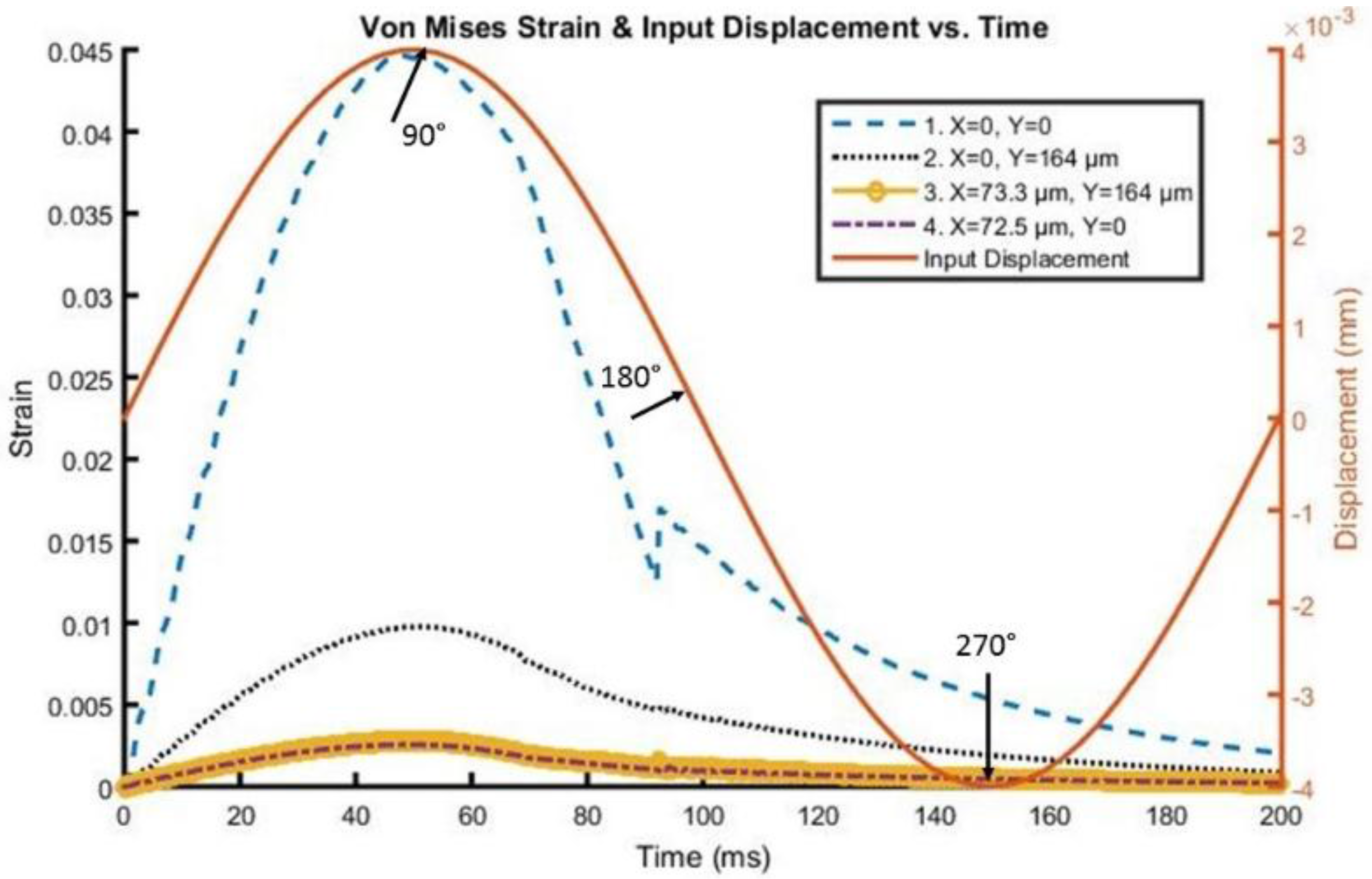
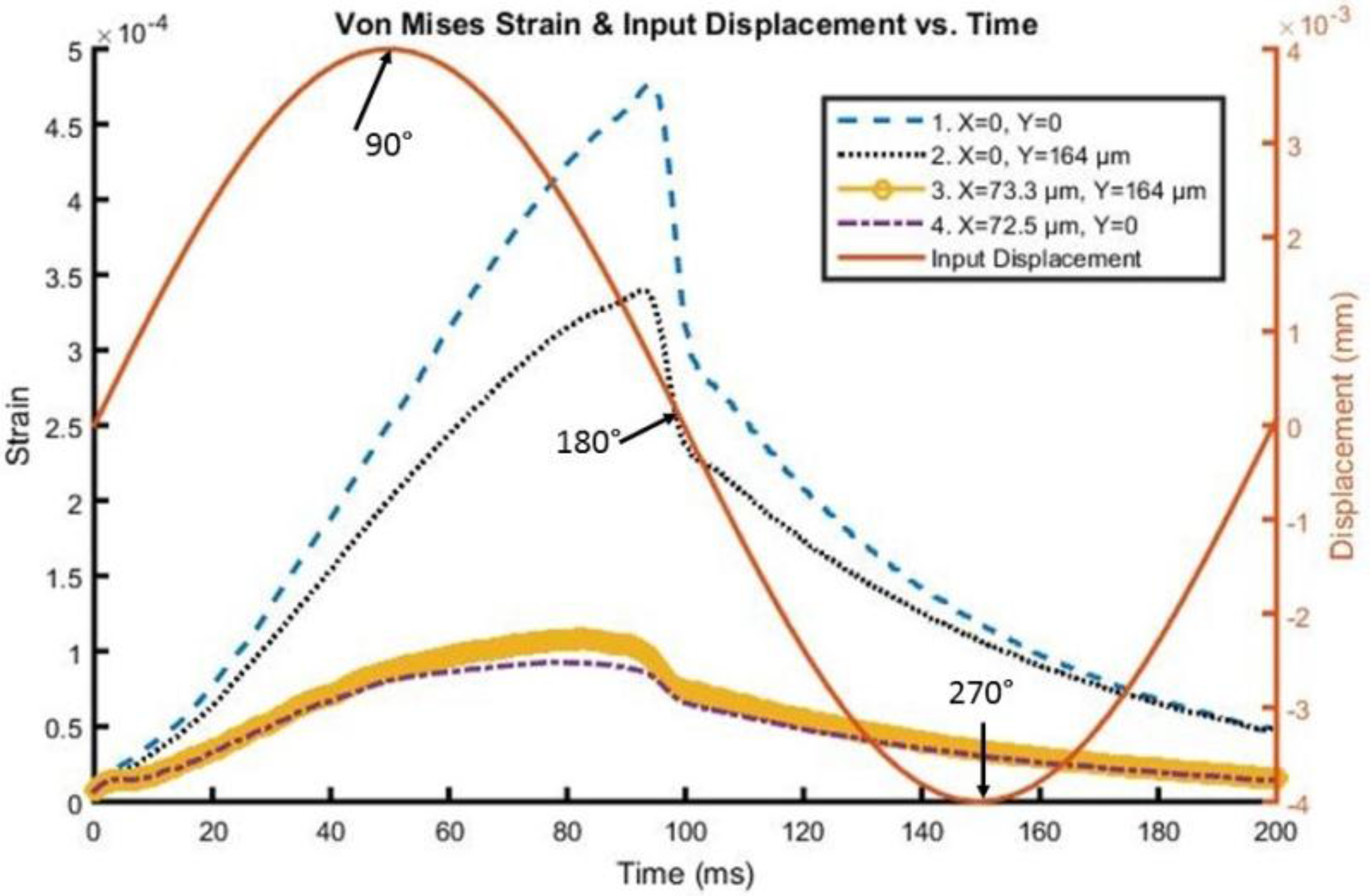
| Frequency | Side Interface Strain with 0.3 COF | Side Interface Strain with 0.6 COF | Side Interface Strain with 1 COF |
|---|---|---|---|
| 1 Hz | 0.0503/2.14e−3 | 0.0474/1.03e−3 | 0.0448/5.67e−4 |
| 5 Hz | 0.052/1.45e−3 | 0.049/6e−4 | 0.0463/3.29e−4 |
| 10 Hz | 0.0529/9.38e−4 | 0.0497/3.27e−4 | 0.0472/2.3e−4 |
| 15 Hz | 0.0535/7.11e−4 | 0.05/2.58e−4 | 0.0478/2.08e−4 |
| 20 Hz | 0.0539/5.91e−4 | 0.0511/2.42e−4 | 0.0487/1.94e−4 |
| 30 Hz | 0.054/5.24e−4 | 0.0514/2.42e−4 | 0.0487/2.06e−4 |
| 40 Hz | 0.0583/5.05e−4 | 0.0552/2.74e−4 | 0.0515/2.33e−4 |
© 2016 by the authors; licensee MDPI, Basel, Switzerland. This article is an open access article distributed under the terms and conditions of the Creative Commons Attribution (CC-BY) license (http://creativecommons.org/licenses/by/4.0/).
Share and Cite
Polanco, M.; Bawab, S.; Yoon, H. Computational Assessment of Neural Probe and Brain Tissue Interface under Transient Motion. Biosensors 2016, 6, 27. https://0-doi-org.brum.beds.ac.uk/10.3390/bios6020027
Polanco M, Bawab S, Yoon H. Computational Assessment of Neural Probe and Brain Tissue Interface under Transient Motion. Biosensors. 2016; 6(2):27. https://0-doi-org.brum.beds.ac.uk/10.3390/bios6020027
Chicago/Turabian StylePolanco, Michael, Sebastian Bawab, and Hargsoon Yoon. 2016. "Computational Assessment of Neural Probe and Brain Tissue Interface under Transient Motion" Biosensors 6, no. 2: 27. https://0-doi-org.brum.beds.ac.uk/10.3390/bios6020027