Most Frequent Problems of Building Structures of Urban Apartment Buildings from 2nd Half of 19th Century and the Start of 20th Century

Faculty of Civil Engineering, Czech Technical University in Prague, 166 36 Prague 6, Czech Republic
Buildings 2021, 11(1), 27; https://0-doi-org.brum.beds.ac.uk/10.3390/buildings11010027
Submission received: 8 December 2020
/
Revised: 29 December 2020
/
Accepted: 1 January 2021
/
Published: 12 January 2021
(This article belongs to the Special Issue Assessment, Diagnosis and Service Life Prediction)
Abstract
:An urban residential building from the second half of the 19th century and the start of the 20th century, the so-called tenement house, is a significant representative of the architecture of the developing urban fabric in Central Europe. The vertical and horizontal load-bearing structures of these houses currently tend to show characteristic, repeated defects and failures. Their knowledge may, in many cases, facilitate and speed up the design of the historic building’s restoration without compromising its heritage value in this process. The article presents the summary of the most frequently occurring defects and failures of these buildings. The summary, however, is not an absolute one, and, in the case of major damage to the building, it still applies that, first of all, a detailed analysis of the causes and consequences of defects and failures must be made as a basic prerequisite for the reliability and long-term durability of the building’s restoration and rehabilitation. An integral part of the rehabilitation of buildings must be the elimination of the causes of the appearance of their failures and remediation of all defects impairing their structural safety, health safety and energy efficiency.
1. Introduction
The apartment building became a new phenomenon in Central Europe in the 19th century, although rental flats had been quite common in historic cities, practically from the Middle Ages. However, the situation in individual cities differed. Architect Pavel Janak summed up the situation in his article “One Hundred Years of a Residential Rental House in Prague” (1933): “The situation in Prague and our towns in the 19th century in general is characterized by the non-existence of a family house. Towns are made up of large houses with many flats, built by individuals and rented out. Our culture, or its lack, is based on collective housing in a large building. A family house and family living is not a component of our culture. In the second half of the 19th century, the type of a large house became the subject of unprecedented business. The primary reason why it was built was not to provide flats, but to make money fast. The size of the house and its massive scale were only paralyzed at the end of the 19th century by increased demands for the value of an apartment—leading to the shrinkage of the house to only two apartments on one floor and to the appearance of a family house, a hitherto unknown type of housing” [1].
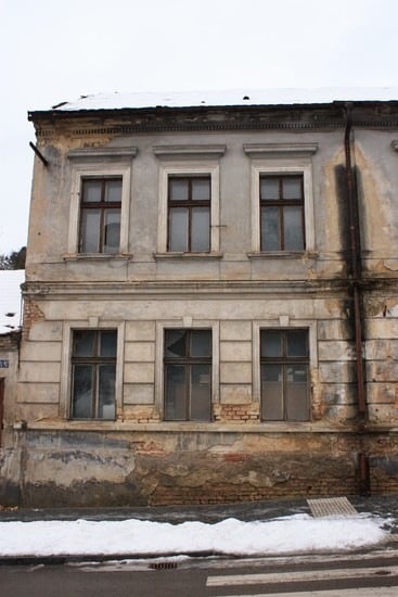
The courtyard tracts of historic houses represent an initial early stage in the development of apartment buildings in Czech cities—while the solidly built foundation of a house with a vaulted ground floor was often left even during a radical reconstruction, the newly built courtyard tracts connected with the house by galleries emerged as completely new structures [2]. In Prague (the capital city of the Czech Kingdom of the Austro-Hungarian Empire of the time) three or, less often, even four-storey houses were built in the busiest streets on the threshold of the 19th century (Figure 1). On side streets, the houses mostly had two to three storeys, and single-storey houses were an exception. The houses had courtyard tracts and the space was often built-up to the maximum extent. The situation differed in other large Czech cities (e.g., Pilsen or Ostrava), where three-storey houses were a rarity; moreover, they were only built in the main squares. Two-storey houses, and single-storey houses in side streets, were much more common there. The former historic royal towns, which usually had around 220 to 250 houses in the “walls”, used to have mostly single-storey houses, and a two-storey house was an exception. At the same time, the smaller the town, the fewer the number of rental flats.
Until the beginning of the 18th century, there were no binding rules in force for the design of buildings. The fundamental construction principles were based on the builders’ efforts to create the required interior space volume defined by vertically laid-out load-bearing structures, divided horizontally by floor structures and enclosed by the roof.
From about the mid-18th to the mid-19th century, the most important areas related to building law were refined, mainly in connection to fire safety. The buildings were designed on the basis of builders’ experience where the thickness of vertical load-bearing structures was determined by empirical formulae depending on the number of storeys, the height of the storeys and the depth of the tract. During the 19th century, three waves of building codes were issued, which partly reflected the development of urban construction practice. The first wave includes the Czech Building Regulations of 1833, the Moravian and Silesian Building Regulations of 1835 and the amended version of the Czech Building Regulations of 1845. The second wave may be represented by the Czech Building Regulations of 1864, the Moravian Building Regulations of 1869 and the Silesian Building Regulations of 1883. The third wave covers the Prague Building Regulations of 1886, which were adopted by Pilsen and České Budějovice in 1887, the Czech Building Regulations of 1889 applying to the rest of the country and two Moravian Building Regulations of 1894 [4].
2. Materials and Methods
Vertical and horizontal load-bearing structures of apartment buildings from the second half of the 19th century currently show, in many cases, characteristic, recurring defects and faults (Figure 2). The main goal of this paper is to identify the most common defects and failures of masonry structures based on field and archival research of building structures and details of masonry buildings from the period. Knowledge of endangered structural details of vertical and horizontal structures, including, for example, the issue of basic construction conditions, is a suitable step to mitigate the consequences of construction and technical problems of historic buildings. At the same time, their knowledge can facilitate and speed up the design of the restoration of a historic building so that no monumental values are lost during this process [5].
A summary of the most common defects and failures of these buildings, presented in the following parts of the article, is based on field research, especially of Prague apartment buildings. The archival research is based on historical building literature of the 19th century and a search of drawing documentation of students of construction schools, which is available at the National Technical Museum in Prague [6].
2.1. Vertical Structures
The primary structural function of vertical masonry structures is to transfer the effects of vertical and horizontal loads from individual floor structures through the foundation structure to the foundation subsoil. Tenement houses from the 19th century, but also shops, schools, hospitals, public buildings, etc., were characterized by the longitudinal layout of load-bearing walls, parallel to the street tract. Inside the building, the load-bearing walls formed the so-called middle walls, where the depth of the tracts most often ranged between 4 and 5 m, exceptionally up to 8 m (palaces, public buildings), while internal tracts were usually less than 4 m deep (Figure 3a). The vertical load-bearing structures of urban apartment buildings were most often executed in mixed masonry and, above all, masonry of solid burnt bricks of the so-called classic format of 290 mm × 140 mm × 65 mm [7,8]. In exceptional cases, the walls of overground storeys in buildings from this period could already be built of hollow burnt-clay bricks or hollow brick-like blocks of lightweight concrete (slag concrete or slag pumice), or blocks of another “modern” material. The end of the 19th century was marked by an increase in the use of rolled iron elements (beams, columns, etc.), to be later followed by a global development of concrete and reinforced concrete structures.
Pursuant to the above building codes, urban residential masonry buildings were characterized by massive walls 300–900 mm thick, where, starting from the second wave of building regulations (i.e., from the second half of the 19th century), a minimum wall thickness of 450 mm was required to prevent frost penetration and was further increased in a downward direction (Figure 3b). Lime or cement-lime mortar was used as the most common bonding material, while the use of cement mortar increased at the end of the century, and, subsequently, in the 20th century.
The stability of the load-bearing system of masonry buildings with several storeys was ensured by longitudinal—front and middle—walls, on which floor structures and transverse walls properly bonded to the longitudinal walls were mounted. The transversely laid-out walls—gable walls, staircase walls, brick partitions 150 mm and 300 mm in thickness—coupled the longitudinal, primarily load-bearing walls, ensuring their stability and contributing to the spatial performance of the load-bearing system, and played an important role in enhancing stability.
The so-called wall and beam ties fulfil an important function in terms of ensuring spatial stiffness, stability and resistance to the effects of forced deformations (Figure 4). From the beginning of the 19th century, wrought iron wall ties were used in walls and vaults, where they served to stiffen and clamp the building and absorb oblique compressive loads, particularly during masonry settling and the additional compression of foundation soil.
2.2. Horizontal Structures
In the majority of urban apartment buildings from the second half of the 19th and the start of the 20th century, various types of floor structures can be found. From a fireproof point of view, ceiling structures are one of the most important parts of the building. At the same time, the fire safety properties of horizontal structures not only reflect their historical development, but also represent an important criterion in categorization. “Numerous construction ceilings can be divided into more or less completely combustion—if it had used exclusively wood because besides still other substances—and incombustible in which wood is unfit on at all.” [7] (p. 72).
With regard to the ability of horizontal structures to resist the effects of fire, ceilings of the monitored period can be divided into:
- -
- combustible floor structures (e.g., a simple wooden beamed ceiling with a flap, i.e., with visible wooden beams),
- -
- semi-combustible floor structures, fitted with a ceiling embankment of at least 80 mm thick at the upper face, while at the lower face, the wooden beam structure is usually protected by undercover of planks covered by reed plaster (e.g., beam ceiling with reed plaster, flap and ceiling embankment etc.),
- -
- non-combustible floor structures, i.e., made of bricks, concrete, cast or wrought iron or later mild steel, “… in which wood is not used at all. … A safe, non-combustible ceiling is provided by a vault. Large spaces cannot be bridged by individual arches for several reasons, mainly because they require strong retaining walls, narrow the spaces and are expensive. The effort to eliminate these defects leads to division of by structures serving as support for smaller vaults. First, it tracks the vault, then the iron beams of either rolling surface (traverse) or riveted (tin) in shape, providing at least a quantity of the spent materials greatest resistance against bending.” [7] (p. 77).
According to current knowledge, the above-mentioned division of ceiling structures, from the point of view of fire resistance, is overly simplified and inaccurate [11,12]. Nevertheless, at the time of formulating the above-cited building regulations, it was a significant step to increase the safety of buildings, i.e., also city apartment buildings.
The dominating types of horizontal structures used were combustible and semi-combustible floor structures. Specific types of floors include, in particular, wooden beam floors with subflooring and, later, also with reed plaster, or an upright plank floor with diagonal braces with reed plaster, subflooring and an embankment, etc.
In rooms with strict fire safety requirements, i.e., mainly in public buildings, but also in some areas of apartment buildings (e.g., the ground floor), non-combustible floor structures were mostly designed. In the apartment buildings of the 19th century, vaults were considered to be a safe, non-combustible ceiling structure (or were required by law and building regulations for the Czech Kingdom). The vaults were used (or required by the building codes) in gateways, entrances to houses, cellars and potentially, if necessary, in staircases, corridors and on the ground floor of apartment buildings were considered as safe, non-combustible floor structures. They were usually of a wagon vault type with arch rings, and, later, flat mirrored vaults were used. In this period, the non-combustible ceiling structures used also included segmental vaults made of solid fired bricks vaulted between the beams made from cast iron, wrought iron or later steel (Figure 5). The structures used at the turn of the 19th and early 20th centuries also included various types of masonry floor structures derived from a barrel vault, so-called straight or flat vaults made up of ceramic masonry elements, and, later, of plain or reinforced concrete.
3. Results
The main causes of degradation processes, which generally lead to the deterioration of the required properties of materials and structures, are, on the one hand, specific properties of building materials (their composition, structure, etc.) and, on the other hand, time-variable parameters of the exterior environment in which buildings and their parts perform [17,18]. Different degradation processes caused by climatic factors differ from each other in their duration and type of effect. Some last for fractions of a second, while others for days, months or even years. These parameters, together with material parameters, create the conditions that will initiate or accelerate mechanical, mineralogical, physical, chemical and biological degradation processes [19]. It may be summarized that the defects and failures of structures from the second half of the 19th and the start of the 20th century are most frequently caused by design defects, material defects, by degradation processes triggered mainly by moisture, by incorrect design solutions, faulty workmanship, usage and by neglected maintenance [20,21,22].
3.1. Vertical Structures
A frequent cause of failures of vertical masonry structures of buildings from the second half of the 19th and the start of the 20th century, which are manifested by cracks, crushing and spalling of surface layers, etc., is poor quality and strength of the masonry in compression and tension plus some other effects, such as different properties of the masonry elements made of mixed masonry or multi-leaf masonry, respectively, low compressive and tensile strength of masonry elements and mortar, etc. [23]. The quality of the masonry and its load-bearing capacity result from the quality of the masonry elements, the bonding mortar and masonry workmanship, but, in particular, from compliance with the principles of proper masonry bonding [24]. The quality of masonry is also significantly affected by increased moisture levels or its aggressiveness and associated degradation processes.
Defects in masonry are caused by imperfect project documentation or imperfect or incorrect execution. The most common execution defect is non-compliance with the principles of proper bonding. The defects in masonry subsequently manifested by the occurrence of failures, insufficient load-bearing capacity, low resistance to degradation processes and others, include:
- poor quality of mortar (composition, excessive grain size of aggregates, low adhesion, shrinkage, poor workability, non-homogeneity) [25],
- non-observance of the planeness and verticality of masonry elements.
In the case of buildings from the second half of the 19th and the start of the 20th century, the cause of these failures resulting from a change in the footing bottom shape is an error in their project preparation, which lacked a geological survey of foundation conditions. At the same time, the empirical design of building structures and insufficient knowledge of the above-mentioned issues led to the construction of foundation structures with insufficient stiffness, without expansion joints and to insufficient reinforcement of the load-bearing masonry at the level of floor structures (by wall and beam ties, bond beams, tie rods, etc.).
The failures of vertical load-bearing masonry structures are crucial in terms of ensuring the mechanical resistance and stability of the load-bearing system. Structural (mechanical) failures of masonry structures and buildings are caused by the response of the building structure to static loads and the deformation effect of some loads and non-force effects, or to static loads with a dynamic component. The most common manifestations of these failures are excessive deformations and strains, cracks (failure in tension and shear), crushing (failure in compression) and local mechanical damage arising due to insufficient load-bearing capacity, in places of stress concentrations, as a result of a change in loading, long-term deformations, degradation and disintegration of masonry, or due to unprofessional interventions. (Figure 6) [28,29,30]. These failures are directly related to the structural behaviour of the load-bearing structure and affected by their occurrence in the structural performance of the load-bearing system, either locally or as a whole—they are critical in terms of ensuring the mechanical resistance and stability of the supporting system [31,32].
Non-structural failures of masonry structures and buildings are caused by the interaction of materials used for individual structures with the external environment, manifested, above all, by increased moisture levels, chemical, mineralogical and biological processes which weaken the required properties of structures and cause their gradual deterioration and disintegration—degradation processes [33].
The failures of masonry are closely related to the failures of the adjoining masonry structures—vaults, springers and lintels, relief vaults, cavettos and soffits of wooden ceilings. Attention must also be paid to potential defects without visually observable manifestations (cavities and plastered grooves in masonry, different quality of individual masonry components, etc.).
In summary, the most frequently occurring defects and failures of vertical structures of buildings from the second half of the 19th and the start of the 20th centuries include:
- tensile and shear cracks due to the effect of spatial stress states arising in the place of the concentration of compressive stresses in masonry exerted by the mounting of floor beams and girders (or masonry crushing due to the effect of concentrated compression);
- weakening of masonry of e.g., load-bearing pillars by continuous horizontal or vertical grooves, larger openings or the installation of elements differing significantly in stiffness, which contribute to the masonry damage and cracking;
- volume changes due to temperature: unequal or different susceptibility to volume changes caused by the temperature effect can result in different stress states and subsequent failures, e.g., formation of shear cracks, e.g., in the contact between mutually perpendicular masonry walls (perimeter and internal) [34];
- shear forces between the parts of masonry with different temperatures cause micro-bending deformations and, as a result, can lead e.g., to the failure of the vault mounted on the masonry wall by tensile cracks or damage to the joint between the masonry and the floor structure, etc.;
- sinking of a cantilevered floor structure on which the perimeter masonry of a bay window is mounted; the sinking will cause the appearance of tensile cracks in the bay window masonry whose pattern corresponds to the time pattern of compression trajectories;
- failures of vertical masonry structures built on heterogeneous foundations, in unstable subsoil conditions or in undermined areas is caused by forced deformations, due to the effect of a change in the shape of the footing bottom, i.e., non-uniform subsidence (e.g., due to waterlogging of the foundation joint, e.g., due to leaks in utility networks, waste pipes and incorrect slope of the prepared terrain) or curvature of the footing bottom [35,36].
A change in the shape of the footing bottom and subsequent masonry failures might also have occurred as a result of building activity in the surroundings, e.g., extension of the building, vehicle traffic (dynamic effects causing compaction of the subsoil, shocks of the building), or a change in hydrogeological conditions, waterlogging or frost penetration into the footing bottom of the existing foundation during the erection of a neighbouring building, additional loading of the foundation, dynamic effects and shocks during the construction of a neighbouring building, etc. (Figure 7) [37].
A serious problem of urban masonry apartment buildings is the degradation and disintegration of damp masonry and surface coatings due to the action of moisture contaminated by soluble salts and weak acid solutions. The chemical processes disintegrate the binder component of masonry elements, and the binder and the salts which are the product of these reactions create pressures in the masonry pore system during a change in moisture and degrade its integrity, causing the spalling and disintegration of coatings and layers.
The prevailing parts of historic buildings from the second half of the 19th and the start of the 20th century suffer from increased moisture levels in the foundation masonry and masonry above the foundation line as a consequence of non-functional or damaged waterproofing of the masonry above the foundation line and the masonry of underground parts of the building, leaks or accidents of water supply and sewerage pipes and mains, poor drainage of the terrain, insufficient ventilation, etc. (masonry moisture in dry state is 1%–3% by weight) [38,39]. In many cases of historic brick buildings, there is no damp proofing, or the damp proofing, ventilation systems, etc. have deteriorated and degraded [40].
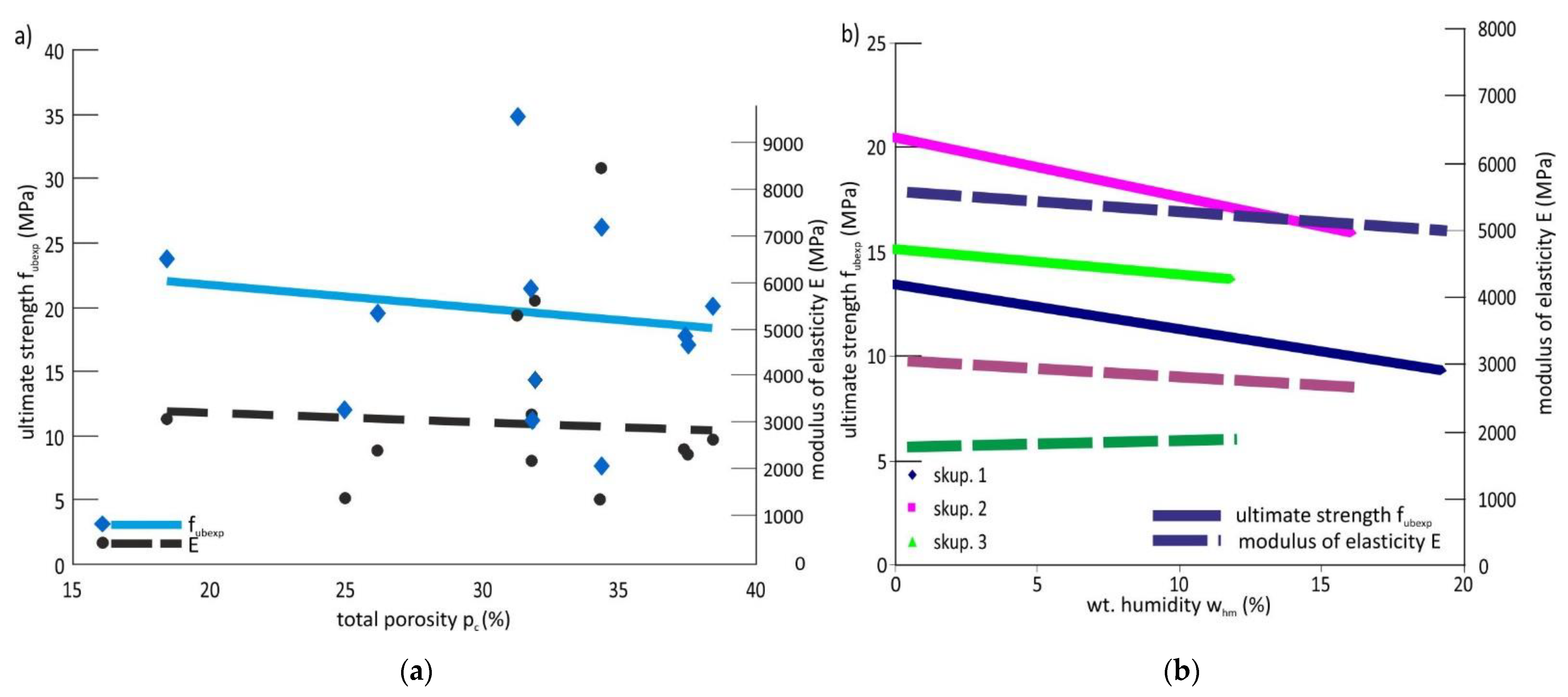
The increased moisture levels of underground and partly overground masonry are usually accompanied by chemical and biological degradation processes, whose intensity depends on the value of increased moisture levels and its aggressiveness. The knowledge and assessment of salinity, especially the content of sulphates, chlorides and nitrates in masonry, are essential for the evaluation of the severity of increased moisture levels and the design of an effective remediation method (Figure 8) [42,43]. Salts with hygroscopic properties and the presence of bacteria and mould in the pore system of masonry, which increase the masonry hygroscopicity, can significantly affect the equilibrium moisture content. Degradation processes usually reduce the content of binder components in the masonry. For these reasons, the assessment of the condition of building structures should include, inter alia, an analysis of the change in total porosity and pore distribution and an assessment of the content of water-soluble salts (Figure 9) [44,45].
3.2. Horizontal Structures
Among the defects of wooden floor structures preceding the occurrence of failures, we might mention, above all, the following: wood infested by wood-destroying fungi or insects, the inappropriate mounting or poor quality workmanship of joints of wooden elements, installation of wood with high moisture levels (whm 12%), impermeable closed-cell wood with initial moisture contents, or closure of high moisture levels in the structure [47].
Other major factors leading to the failures of wooden parts of horizontal load-bearing structures are, among others, the following:
- excessive overall or local loading, wood damaged by unprofessional interventions,
- loosening of joints due to the natural aging and deterioration of major wood properties (water absorption, natural impregnation, elasticity, hardness, strength, toughness),
- thermal bridges in the perimeter masonry in places where wooden beams are mounted in beam pockets, where the wall is weakened by 200 to 250 mm and thus, at the same time, the thermal resistance of these structures is significantly reduced and thermal and moisture conditions of the mounting ends of wooden beams are deteriorated,
- insufficient bending and shear bearing capacity and stiffness of floor beams manifested by their excessive deflection, formation of longitudinal cracks and “slippage” of beams in the places of their mounting and local supports,
- insufficient load-bearing capacity and stiffness of beam floor structures in the horizontal direction (particularly in cases of ineffective or missing wall and beam ties, loosely or insufficiently fixed subflooring to floor beams) can be the cause of a serious threat to structural safety—spatial stiffness—of masonry structures, especially in the case of a building with several storeys, due to horizontal loading effects (eccentricity of vertical loading, non-uniform settlement, wind effects, temperature effects), but mainly dynamic loading effects (caused by technical, induced and natural seismicity); the absence of wall and beam ties, insufficient effectiveness (loosening of joints, insufficient anchoring, etc.) is usually directly manifested by the formation of tensile cracks, damage to the load-bearing masonry and the integrity of the load-bearing system.
The reserves in the stability of massive longitudinal walls in the transverse direction are insufficient and longitudinal load-bearing walls on their own usually cannot ensure the stability of a building with more than 2 overground storeys in relation to cross wind effects and other effects exerting transverse horizontal forces (e.g., effect of differential settlement, dynamic traffic effects, eccentricity of vertical loads transmitted e.g., by beam floors, temperature differences). This problem is often neglected during rehabilitations when the structural safety (spatial stiffness) may be seriously impaired by the demolition of internal transverse, primarily non-load-bearing walls and partitions.
The reinforcement of a wooden floor structure must be preceded by a detailed survey of wooden structures—particularly a mycological and construction and technical survey, removal of damaged or infested wood and basic chemical protection of wood by a suitable coating, or the sterilization of wood at an elevated temperature [50,51]. The most reliable protection measures of wood against biotic wood-destroying agents are preventive measures against their appearance and development, mainly the protection of wood against increased moisture levels (above 15%).
4. Conclusions
The article presents the most common defects and failures of vertical and horizontal structures of apartment buildings from the second half of the 19th century and the beginning of the 20th century. The construction practice of this period was influenced by three successively issued waves of building regulations, which reflected the building boom of this period.
The issues related to defects and failures, degradation processes and the design of rehabilitation measures of buildings from the second half of the 19th and the start of the 20th century include a wide range of topics of interdisciplinary nature, from the natural sciences, materials engineering, mechanics, elasticity and structural theory of building structures to the knowledge of historical materials, structures and technologies. The knowledge of historical structures, materials and construction methods used helps us to prevent errors in the rehabilitation and restoration of prominent, mainly heritage buildings to the original state.
A precise analysis of the causes and consequences of defects and failures is the basic prerequisite for the reliability and long-term durability of rehabilitation and remediation measures. An integral part of the reconstruction and renovation of buildings must be the elimination of the causes of failures, remediation of all defects that reduce their structural safety, health safety and energy efficiency. To ensure the durability of reconstructed buildings, degradation and corrosive processes caused mainly by chemical and biochemical processes and non-force effects of temperature and moisture must be prevented and adequate protective measures must be taken. In this respect, the protection of buildings and their individual parts against the effects of increased moisture levels is of primary importance.
Funding
This research was funded by the Ministry of Culture of the Czech Republic.
Institutional Review Board Statement
Not applicable.
Informed Consent Statement
Not applicable.
Data Availability Statement
Data available in a publicly accessible repository.
Acknowledgments
This article was written as part of the NAKI DG18P02OVV038 research project “Traditional City Building Engineering and Crafts at the Turn of 19th and 20th Centuries (2018–2022, MK0/DG)”.
Conflicts of Interest
The author declare no conflict of interest.
References
- Janák, P. Sto Let Obytného Domu Nájemného v Praze; Styl, Roč. XIII; Styl: Prague, Czech Republic, 1933; p. 63. [Google Scholar]
- Dulla, M. Kapitoly z Historie Bydlení; CTU in Prague: Prague, Czech Republic, 2014; ISBN 978-80-01-05433-8. [Google Scholar]
- Drawing No. 312. Archive of the National Technical Museum: Fund 55—University of Technology Prague, Civil Engineering. Available online: http://www.ntm.cz/en (accessed on 12 January 2021).
- Ebel, M. Dějiny Českého Stavebního Práva; ABF—Arch: Prague, Czech Republic, 2007; ISBN 978-80-86905-21-1. [Google Scholar]
- Anzani, A.; Cardani, G.; Condoleo, P.; Garavaglia, E.; Saisi, A.; Tedeschi, C.; Tiraboschi, C.; Valluzzi, M.R. Understanding of historical masonry for conservation approaches: The contribution of Prof. Luigia Binda to research advancement. Mater. Struct. 2018, 51, 140. [Google Scholar] [CrossRef]
- Kroftova, K. (Ed.) Tradiční Městské Stavitelství a Stavební Řemesla na Přelomu 19. a 20. Století—Svislé a Vodorovné Konstrukce; CTU in Prague: Praha, Czech Republic, 2020; ISBN 978-80-01-06795-6. [Google Scholar]
- Pacold, J. Konstrukce Pozemního Stavitelství; Díl II.; Fr. Rivnac Publisher: Prague, Czech Republic, 1890. [Google Scholar]
- Niklas, J.; Šanda, F. J. P. Jöndlovo Poučení o Stavitelství Pozemním; I. L. Kober Publisher: Prague, Czech Republic, 1865. [Google Scholar]
- Archive of the Architecture of the National Technical Museum: Fund 197, No. 20090909/02.
- Drawing No. 263. Archive of the National Technical Museum: Fund 55—University of Technology Prague, Civil Engineering. Available online: http://www.ntm.cz/en (accessed on 12 January 2021).
- Maraveas, C.; Wang, Y.; Swailes, T. Fire resistance of 19th century fireproof flooring systems: A sensitivity analysis. Constr. Build. Mater. 2014, 55, 69–81. [Google Scholar] [CrossRef]
- Maraveas, C.; Wang, Y.; Swailes, T. Thermal and mechanical properties of 19th century fireproof flooring systems at elevated temperatures. Constr. Build. Mater. 2013, 48, 248–264. [Google Scholar] [CrossRef]
- Archive of the Architecture of the National Technical Museum: Fund 121—Work of pupils of various vocational schools, No. 20060524.
- Kohout, J.; Tobek, A. Konstruktivní Stavitelství; Part 1; V. Nejedly Publisher: Jaromer, Czech Republic, 1911. [Google Scholar]
- Ondřej, S. Stavba Domu v Praksi; E. Gregr and Son Publisher: Prague, Czech Republic, 1932. [Google Scholar]
- Drawing No. 275. Archive of the National Technical Museum: Fund 55—University of Technology Prague, Civil Engineering. Available online: http://www.ntm.cz/en (accessed on 12 January 2021).
- Kroftová, K. Noninvasive Methods of Stabilization and Consolidation of the Historical Surfaces; Habilitation Thesis; CTU Publishnig: Praha, Czech Republic, 2018. (In Czech) [Google Scholar]
- Thomaz, E.; Sousa, H.; Roman, H.R. Defects in Masonry Walls Guidance on Cracking: Identification, Prevention and Repair; CIB: Rotterdam, The Netherlands, 2014; ISBN 978-90-6363-090-4. [Google Scholar]
- Witzany, J.; Karas, J.; Zlesák, J.; Kupilík, V. Hodnocení vlivu degradačních procesů a historie zatížení na únosnost zděných konstrukcí. In Sborník Vědeckovýzkumných Grantových Úkolů v Roce 1994; CTU in Prague: Prague, Czech Republic, 1995; pp. 38–39. [Google Scholar]
- Drdácký, M.; Slizkova, Z.; Valach, J. (Eds.) Příspěvek Technických Věd k Záchraně a Restaurování Památek; ÚTAM AV ČR: Prague, Czech Republic, 2015. [Google Scholar] [CrossRef]
- Domingues, J.C.; Ferreira, T.M.; Vicente, R.; Negrão, J.H. Mechanical and Typological Characterization of Traditional Stone Masonry Walls in Old Urban Centres: A Case Study in Viseu, Portugal. Buildings 2019, 9, 18. [Google Scholar] [CrossRef] [Green Version]
- Cooper, A.J. Structural Failure Patterns of Mid-Nineteenth Century Masonry Buildings of Charleston. Master’s Thesis, Clemson University, Charleston, CA, USA, 2018. Available online: https://tigerprints.clemson.edu/all_theses/2830 (accessed on 27 December 2020).
- Binda, L.; Saisi, A.; Tiraboschi, C. Investigation procedures for the diagnosis of historic masonries. Constr. Build. Mater. 2000, 14, 199–233. [Google Scholar] [CrossRef]
- Witzany, J.; Čejka, T.; Sýkora, M.; Holický, M. Assessment of compressive strength of historic mixed masonry. J. Civ. Eng. Manag. 2015, 22, 391–400. [Google Scholar] [CrossRef]
- Girsa, V.; Michoinova, D. Historicke Omitky—Zachrana, Konzervace, Obnova; CTU in Prague: Prague, Czech Republic, 2013; ISBN 978-80-01-05229-7. [Google Scholar]
- Witzany, J.; Zigler, R.; Čejka, T.; Pospíšil, P.; Holický, M.; Kubát, J.; Maroušková, A.; Kroftová, K. Physical and Mechanical Characteristics of Building Materials of Historic Buildings. Civ. Eng. J. 2017, 4, 343–360. [Google Scholar] [CrossRef]
- Matysek, P.; Witkowski, M. A Comparative Study on the Compressive Strength of Bricks from Different Historical Periods. Int. J. Arch. Herit. 2016, 10, 396–405. [Google Scholar] [CrossRef]
- Research MSM6840770001. Spolehlivost, Optimalizace a Trvanlivost Stavebních Materiálů a Konstrukcí; Faculty of Civil Engineering, CTU in Prague: Praha, Czech Republic, 2010. [Google Scholar]
- Kotlík, P.; Šrámek, J.; Kaše, J. Monografie STOP (2000): Opuka; STOP: Praha, Czech Republic, 2000. [Google Scholar]
- Rovnaníková, P. Monografie STOP: Omítky—Chemické a Technologické Vlastnosti; STOP: Praha, Czech Republic, 2002. [Google Scholar]
- Zigler, R. Rekonstrukce a sanace nosných zděných kosntrukcí (mechanismus porušování tlařených zděných konstrukcí). Ph.D. Thesis, ČVUT, Fakulta stavební, Katedra konstrukcí pozemních staveb, Praha, Czech Republic, 19 June 2006. [Google Scholar]
- Zigler, R. Analýza napjatosti, přetváření a porušování tlačených zděných prvků (stěna, pilíř, valená klenba) se zaměřením na vliv účinku vlhkosti. Master’s Thesis, ČVUT, Fakulta stavební, Katedra konstrukcí pozemních staveb, Praha, Czech Republic, 21 January 1999. [Google Scholar]
- Witzany, J.; Wasserbauer, R.; Cejka, T.; Kroftova, K.; Zigler, R. Obnova a Rekonstrukce Staveb. Poruchy, Degradace, Sanace; CTU in Prague: Prague, Czech Republic, 2018; ISBN 978-80-01-06360-6. [Google Scholar]
- Beran, P. The impact of the masonry temperature during restoration to the thermal stress of historic masonry. In Proceedings of the Fifteenth International Conference on Civil, Structural and Environmental Engineering Computing, Civil-Comp Proceedings, Praha, Czech Republic, 1–4 September 2015; Kruis, J., Tsompanakis, Y., Topping, B.H.V., Eds.; Kippen: Civil-Comp Press: Stirlingshire, UK, 2015; Volume 108. [Google Scholar] [CrossRef]
- Roca, P.; Lourenco, P.B.; Gaetani, A. Historic Construction and Conservation—Materials, systems and Damage; Routledge: Abingdon-on-Thames, UK, 2019; ISBN 9780429052767. [Google Scholar] [CrossRef]
- Kuklík, P.; Brouček, M. Vliv Hydraulických Gradientů a Kolísání Hladiny Podzemních Vod na Stabilitu Staveb; Zpravodaj ČSVTS: Prague, Czech Republic, 2017; Volume 43, pp. 48–51. [Google Scholar]
- Bradáč, J. Základové Konstrukce; Akademické Nakladatelství CERM: Brno, Czech Republic, 1995. [Google Scholar]
- Witzany, J.; Zigler, R.; Čejka, T.; Maroušková, A.; Kubát, J. Research into the effect of grouting on physical-mechanical properties of historic masonry. In Advances in Engineering Materials Structures and Systems: Innovations, Mechanics and Applications; Taylor & Francis: London, UK, 2019; pp. 617–618. ISBN 978-1-138-38696-9. [Google Scholar]
- Witzany, J.; Hruška, A.; Zlesák, J.; Zigler, R. Vliv vlhkosti na redistribuci napětí tlačených zděných konstrukcí. In 11. Mezinárodní Vědecká Konference VUT Brno; VUT v Brně: Brno, Czech Republic, 1999; pp. 239–242. [Google Scholar]
- Skabrada, J. Konstrukce Historickych Staveb; Argo: Prague, Czech Republic, 2003; ISBN 80-7203-548-7. [Google Scholar]
- Ottosen, L.M.; Pedersen, A.J.; Rörig-Dalgaard, I. Salt-related problems in brick masonry and electrokinetic removal of salts. J. Build. Apprais. 2007, 3, 181–194. [Google Scholar] [CrossRef]
- Hendrickx, R. Using the Karsten tube to estimate water transport parameters of porous building materials. Mater. Struct. 2013, 46, 1309–1320. [Google Scholar] [CrossRef]
- Fára, P. Monografie STOP: Sanace Vlhkého Zdiva; STOP: Prague, Czech Republic, 2003. [Google Scholar]
- Drawing No. 307. Archive of the National Technical Museum: Fund 55—University of Technology Prague, Civil Engineering. Available online: http://www.ntm.cz/en (accessed on 12 January 2021).
- Delgado, J.M.P.Q.; Guimarães, A.S.; De Freitas, V.P.; Antepara, I.; Kočí, V.; Černý, R. Salt Damage and Rising Damp Treatment in Building Structures. Adv. Mater. Sci. Eng. 2016, 2016, 1–13. [Google Scholar] [CrossRef] [Green Version]
- Cejka, T. Experimentální Výzkum Vlivu Vlhkosti na Mechanické Vlastnosti Historických Zděných Konstrukcí; Habilitation Thesis; CTU Publishnig: Praha, Czech Republic, 2009. (In Czech) [Google Scholar]
- Reinprecht, L.; Štefko, J. Dřevěné Stropy a Krovy; ABF publisher: Prague, Czech Republic, 2000; ISBN 80-86165-29-9. [Google Scholar]
- Šimůnková, E.; Kučerová, I. Monografie STOP: Dřevo; STOP: Prague, Czech Republic, 2008. [Google Scholar]
- Ryparová, P.; Wasserbauer, R.; Rácová, Z. The Cause of Occurrence of Microorganisms in Civil Engineering and the Dangers Associated with their Growth. Procedia Eng. 2016, 151, 300–305. [Google Scholar] [CrossRef] [Green Version]
- Kloiber, M.; Drdácký, M. Diagnostika Dřevěných Konstrukcí; ČKAIT: Praha, Czech Republic, 2015; ISBN 978-80-87438-64-0. [Google Scholar]
- Drdácký, M.; Kloiber, M. In Situ Compression Stress-Deformation Measurements along the Timber Depth Profile. Adv. Mater. Res. 2013, 778, 209–216. [Google Scholar] [CrossRef] [Green Version]
- Racová, Z.; Loušová, I.; Cejka, T. Protocol No.124029/2019 about the Test: Survey of the Roof of the Tenement House on Poupetova; Prague; CTU: Praha, Czech Republic, 2019. [Google Scholar]
Figure 1.
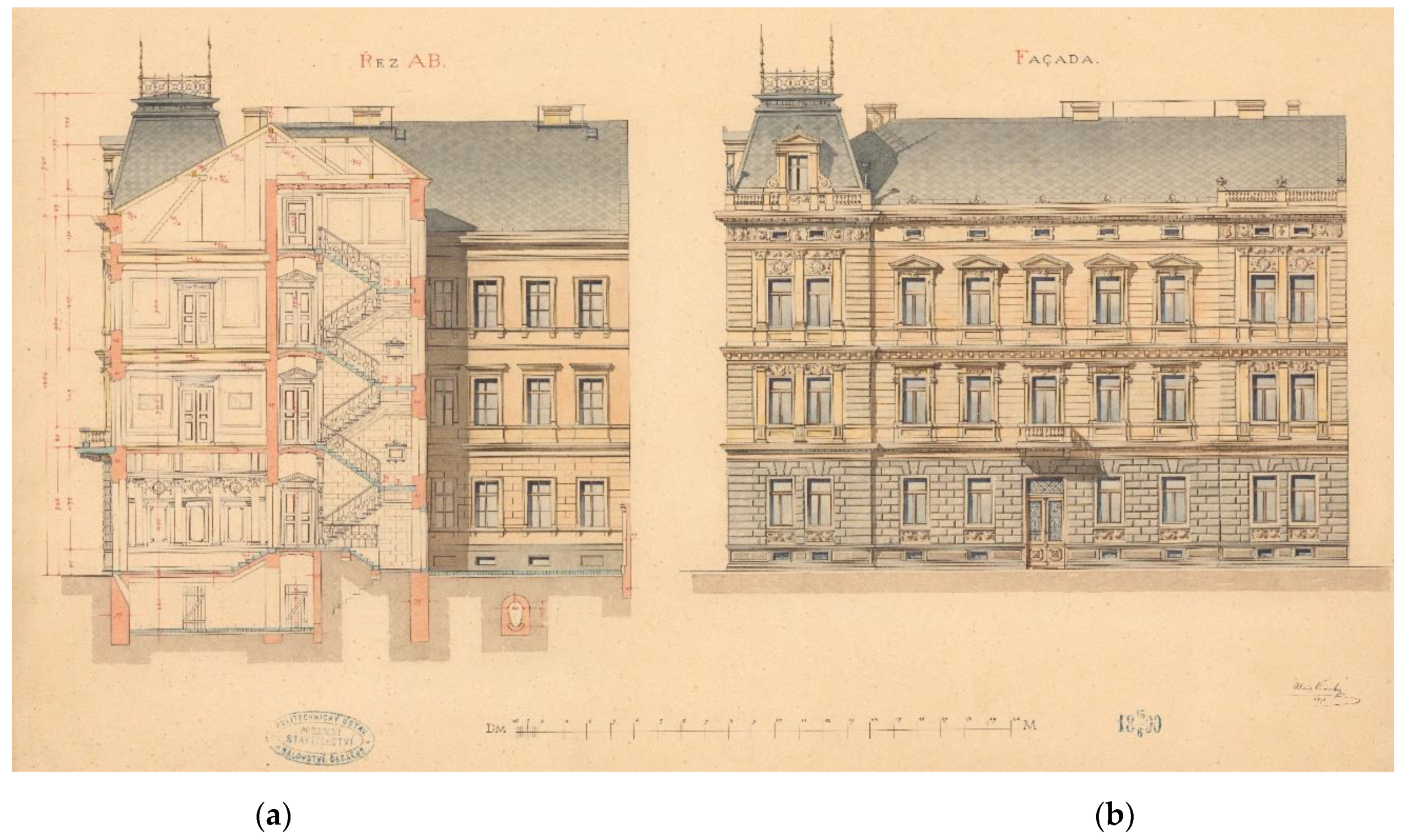
Section (a) and elevation (b) of a typical four-storey tenement house from the end of the 19th century on the student work of A. Censky, 1890 [3].
Figure 1.
Section (a) and elevation (b) of a typical four-storey tenement house from the end of the 19th century on the student work of A. Censky, 1890 [3].

Figure 2.
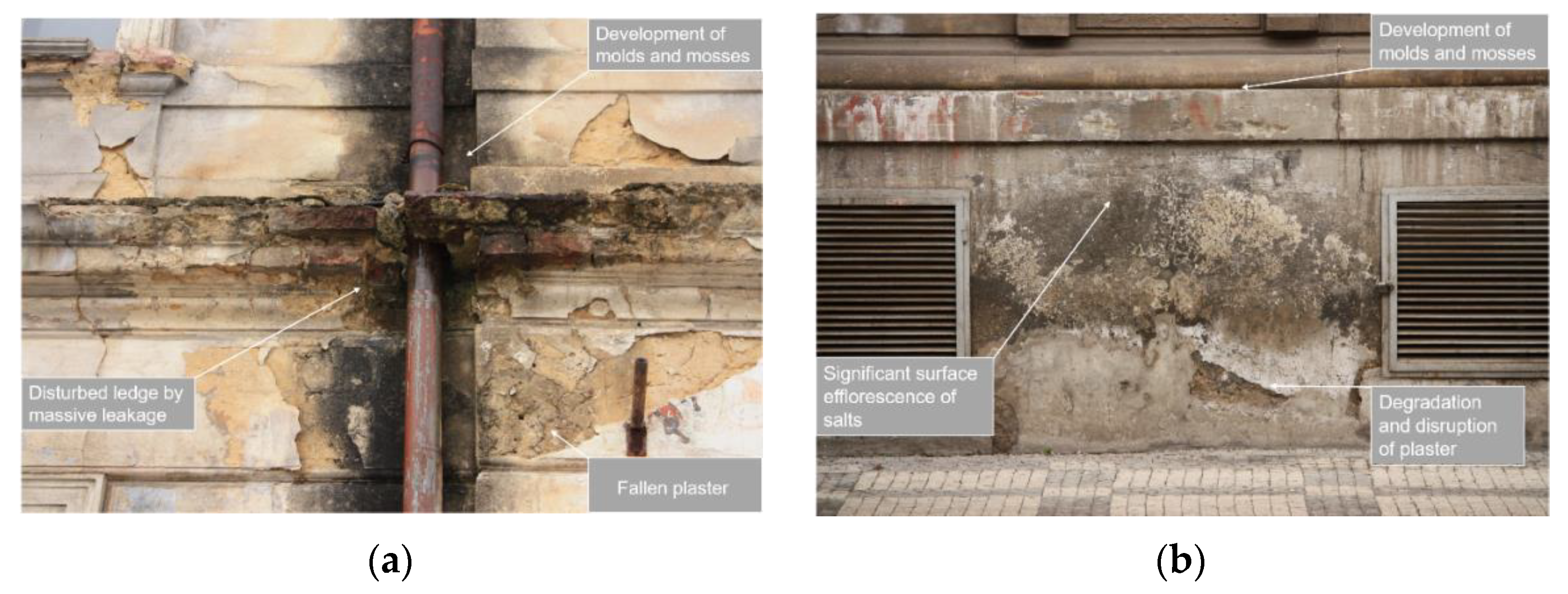
Images clearly showing the most common failures of structures from the second half of the 19th and the early 20th centuries caused by degradation processes initiated in these cases by the combination of moisture, an incorrect design solution and neglected maintenance. The following are clearly visible on images: (a) fallen plaster, damaged ledge by massive leakage, mold and mosses; (b) degradation and disruption of plaster, significant surface efflorescence of salts, mold and mosses.
Figure 2.
Images clearly showing the most common failures of structures from the second half of the 19th and the early 20th centuries caused by degradation processes initiated in these cases by the combination of moisture, an incorrect design solution and neglected maintenance. The following are clearly visible on images: (a) fallen plaster, damaged ledge by massive leakage, mold and mosses; (b) degradation and disruption of plaster, significant surface efflorescence of salts, mold and mosses.

Figure 3.
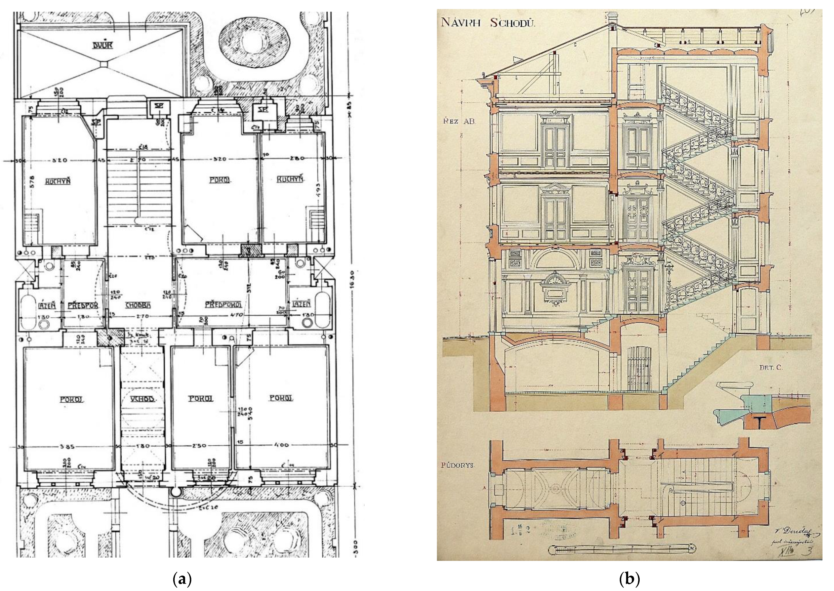
The floor plan and section of urban apartment buildings: (a) floor plan of house with four and two-room apartment, both are equipped with bathrooms (arch. V. Reznicek, early 20th century) [9]; (b) part of a four-storey house with a clearly legible arrangement of the vertical supporting structure with increasing thickness downwards (V. Douda, 1902) [10].
Figure 3.
The floor plan and section of urban apartment buildings: (a) floor plan of house with four and two-room apartment, both are equipped with bathrooms (arch. V. Reznicek, early 20th century) [9]; (b) part of a four-storey house with a clearly legible arrangement of the vertical supporting structure with increasing thickness downwards (V. Douda, 1902) [10].

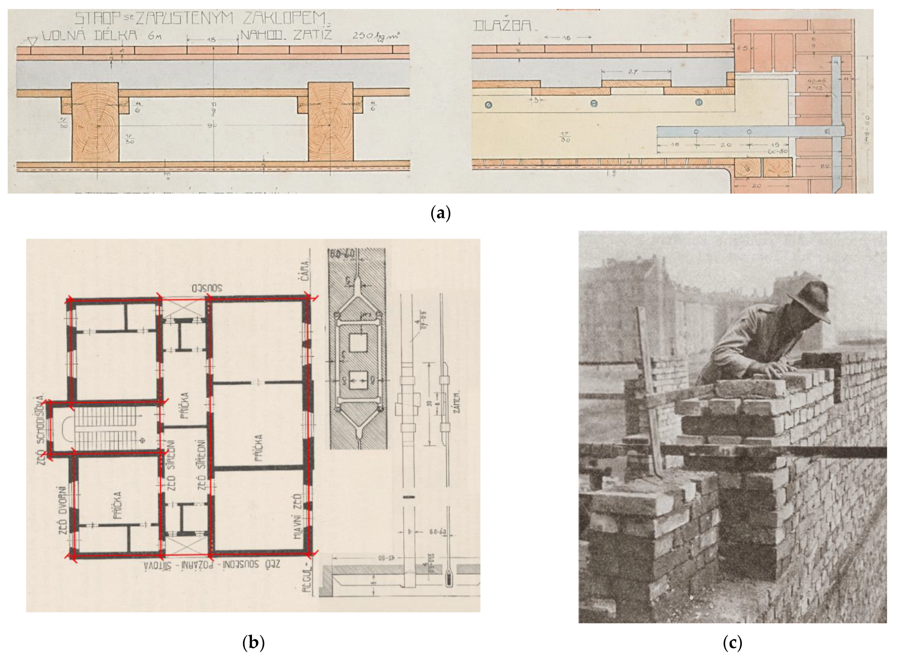
Figure 4.
The wall and beam ties: (a) the beam wrought iron ties in the drawing on the school work of V. Vasatko from 1910 [13]; (b) the detail of the wall ties and their location (red lines) in the floor plan of the house [14]; (c) wall ties made of wrought iron, including adjustment with a lock, on a period photograph (1932) when performing a masonry structure [15].

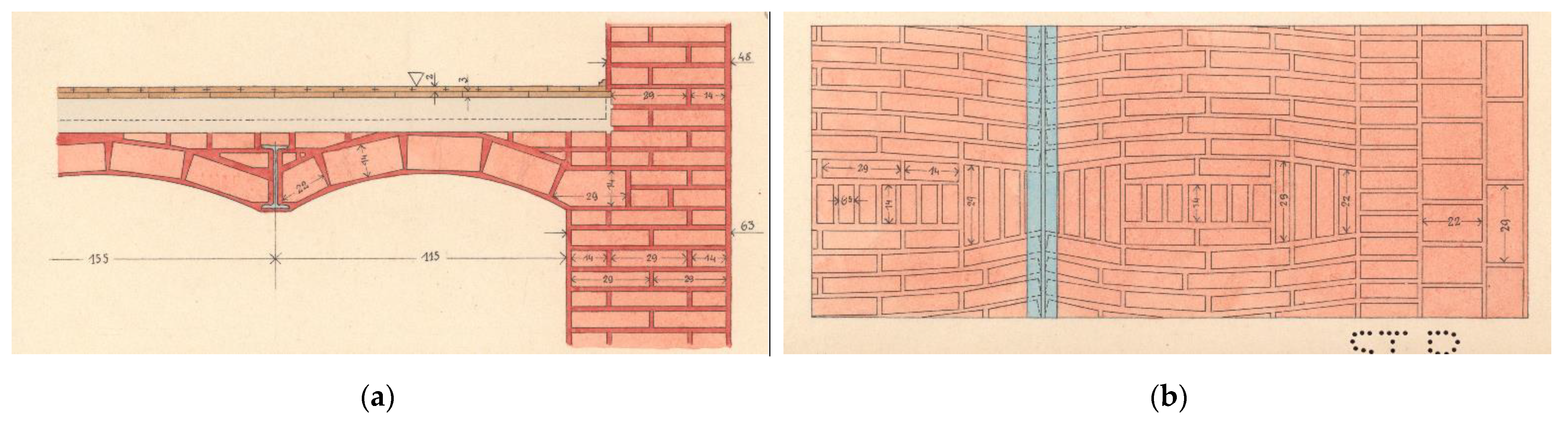
Figure 5.
Detail of a vaulted ceiling in a school project, unknown author, 1920s. Section (a) and top view (b) of a brick vault into traverses with a clearly visible composition of bricks [16].
Figure 5.
Detail of a vaulted ceiling in a school project, unknown author, 1920s. Section (a) and top view (b) of a brick vault into traverses with a clearly visible composition of bricks [16].

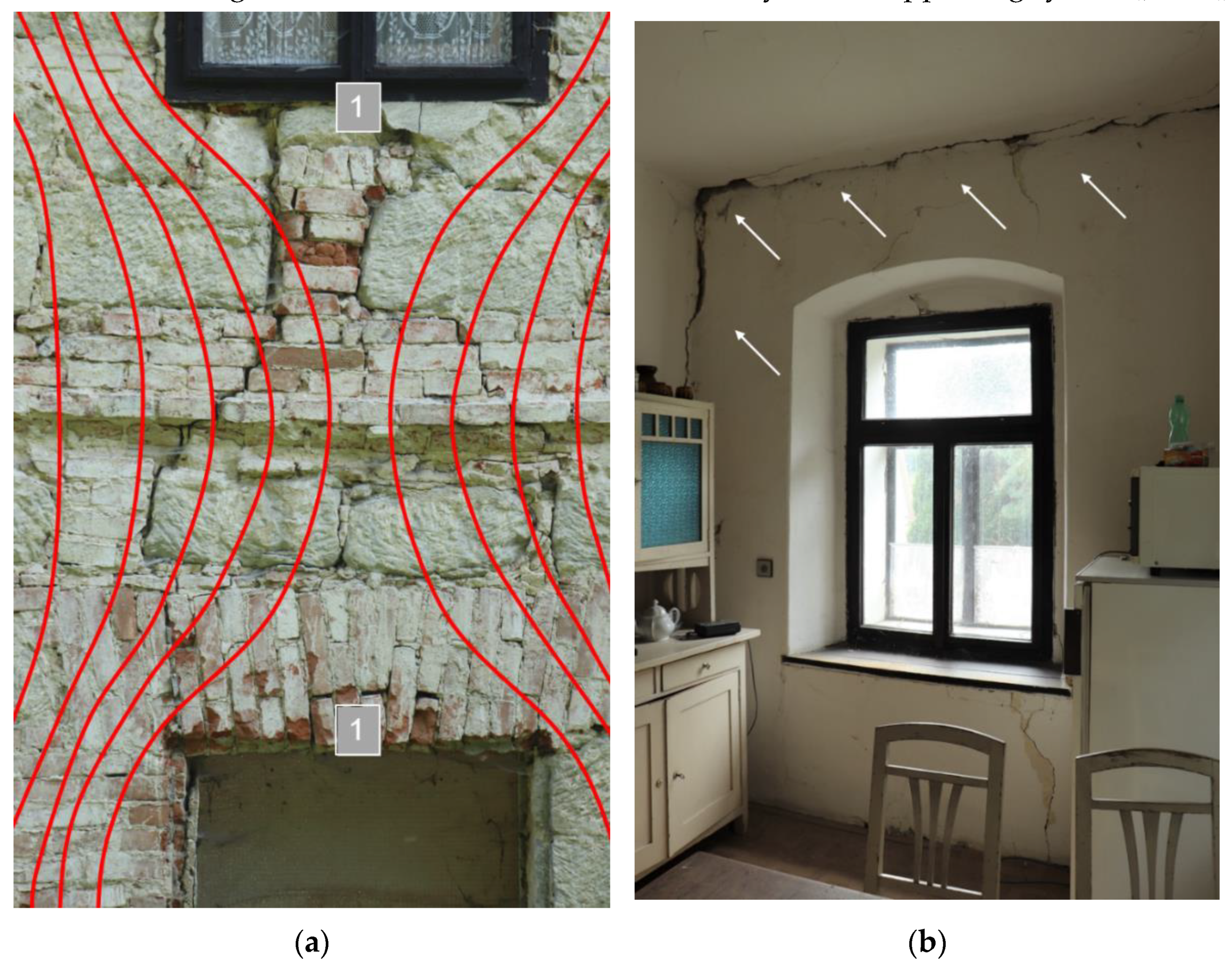
Figure 6.
Examples of structural failures of structures from the second half of 19th and the start of the 20th century: (a) prominent tensile cracks in masonry weakened by openings, with the representation of pressure trajectories, 1—area of normal stresses and tensile cracks; (b) crack between the perimeter structure and the ceiling caused by forced deformation due to the effect of a change in the footing bottom.

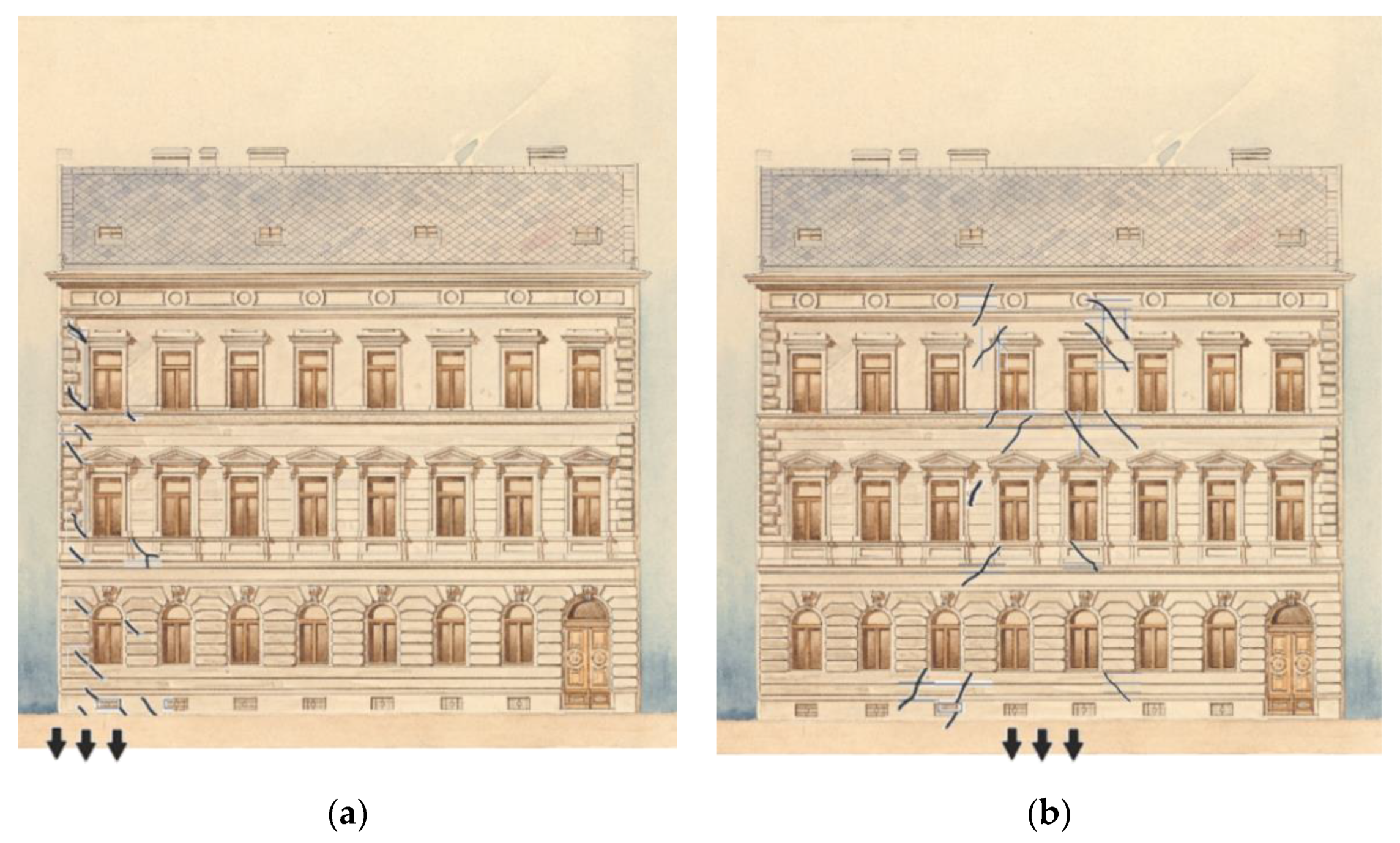
Figure 7.
Graphical representation of the course of cracks and failures of vertical masonry - characteristic tensile cracks on the side (a), resp. in the middle (b) parts of the building, which arose as a result of the decrease of the affected part and thus the change in the shape of the foundation joint, e.g., an uneven foundation conditions (sands – rock), uneven compaction of the substrate or waterlogging of the soil, etc. (arrows indicate the place of decline of part of the foundations) [41].

Figure 8.
Graphical expression of the dependence of the (a) total porosity and modulus of elasticity and ultimate strength, (b) wt. moisture and modulus elasticity and ultimate strength of bricks from the end of the 19th century [46].
Figure 8.
Graphical expression of the dependence of the (a) total porosity and modulus of elasticity and ultimate strength, (b) wt. moisture and modulus elasticity and ultimate strength of bricks from the end of the 19th century [46].

Figure 9.
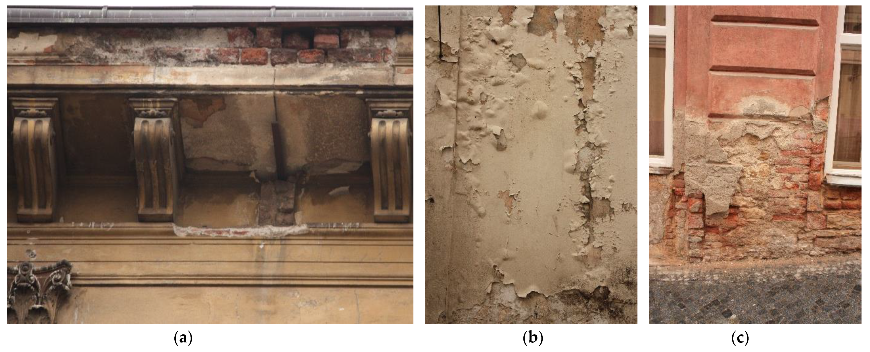
Examples of non-structural failures caused by the effects of the external environment, especially the synergic effect of increased moisture levels and temperature, which are accompanied by chemical, mineralogical and biological processes in structures from the second half of 19th century and the start of 20th century: (a) damage of the ledge and its surface finishes, visible salt efflorescence; (b) closed and open blisters in the surface layers due to their low diffusion permeability; (c) extensive damage to the plinth part caused by the long-term effect of humidity and salts.
Figure 9.
Examples of non-structural failures caused by the effects of the external environment, especially the synergic effect of increased moisture levels and temperature, which are accompanied by chemical, mineralogical and biological processes in structures from the second half of 19th century and the start of 20th century: (a) damage of the ledge and its surface finishes, visible salt efflorescence; (b) closed and open blisters in the surface layers due to their low diffusion permeability; (c) extensive damage to the plinth part caused by the long-term effect of humidity and salts.

Figure 10.
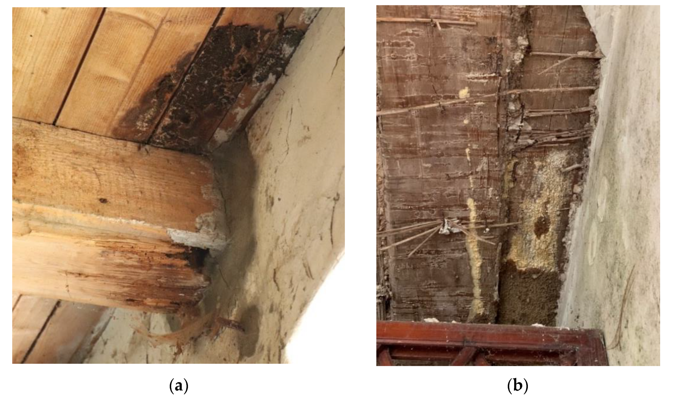
Examples of failures of wooden parts of horizontal load-bearing structures caused by mounting wood without a natural possibility of drying and with insufficient permeability of the structure: (a) rotting head of a wooden ceiling beam; (b) yellow patch of wet rot on ceiling wooden panel.
Figure 10.
Examples of failures of wooden parts of horizontal load-bearing structures caused by mounting wood without a natural possibility of drying and with insufficient permeability of the structure: (a) rotting head of a wooden ceiling beam; (b) yellow patch of wet rot on ceiling wooden panel.

Figure 11.
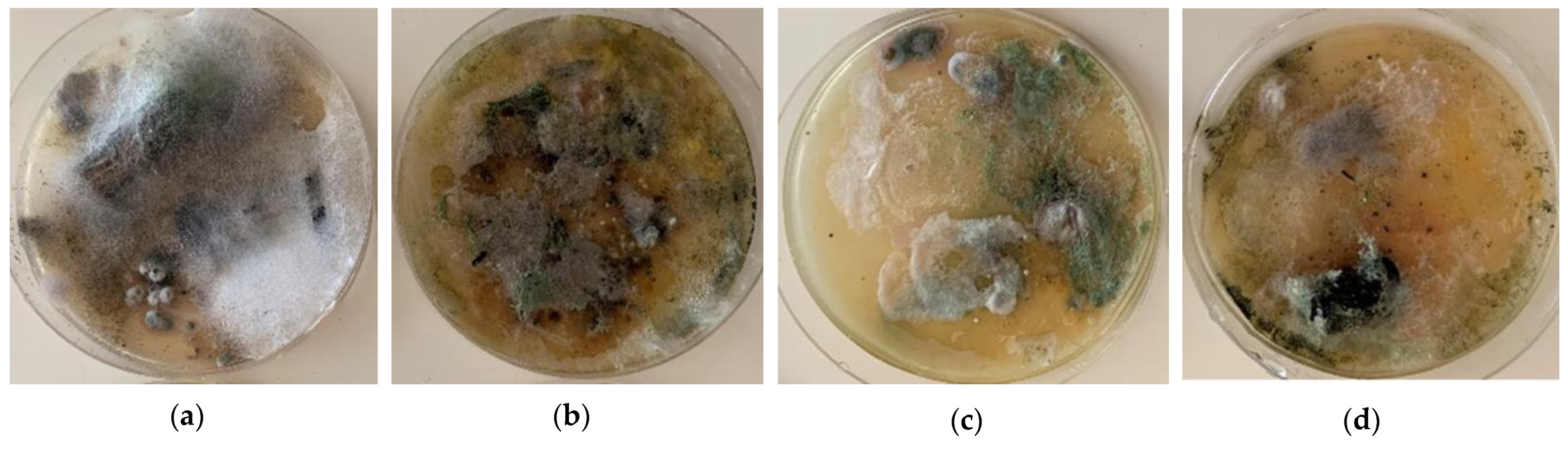
Example of laboratory evaluation of bioderiogents in cultures of a sample of a damaged ceiling structure in Prague 7—confirmed presence of bacteria and fungi. In all cases, massive development and growth of microscopic fibrous fungi was noted. In cultures of samples were identified: (a) Trichoderma sp. and bacterias; (b) Trichoderma sp., Mucor sp., wood-destroying fungus and bacterias; (c) Mucor sp. and wood-destroying fungus; (d) Penicillium sp., Acremonium sp., Aspergillus sp. and bacterias [52].
Figure 11.
Example of laboratory evaluation of bioderiogents in cultures of a sample of a damaged ceiling structure in Prague 7—confirmed presence of bacteria and fungi. In all cases, massive development and growth of microscopic fibrous fungi was noted. In cultures of samples were identified: (a) Trichoderma sp. and bacterias; (b) Trichoderma sp., Mucor sp., wood-destroying fungus and bacterias; (c) Mucor sp. and wood-destroying fungus; (d) Penicillium sp., Acremonium sp., Aspergillus sp. and bacterias [52].

Publisher’s Note: MDPI stays neutral with regard to jurisdictional claims in published maps and institutional affiliations. |
© 2021 by the author. Licensee MDPI, Basel, Switzerland. This article is an open access article distributed under the terms and conditions of the Creative Commons Attribution (CC BY) license (http://creativecommons.org/licenses/by/4.0/).
Share and Cite
MDPI and ACS Style
Kroftova, K. Most Frequent Problems of Building Structures of Urban Apartment Buildings from 2nd Half of 19th Century and the Start of 20th Century. Buildings 2021, 11, 27. https://0-doi-org.brum.beds.ac.uk/10.3390/buildings11010027
AMA Style
Kroftova K. Most Frequent Problems of Building Structures of Urban Apartment Buildings from 2nd Half of 19th Century and the Start of 20th Century. Buildings. 2021; 11(1):27. https://0-doi-org.brum.beds.ac.uk/10.3390/buildings11010027
Chicago/Turabian StyleKroftova, Klara. 2021. "Most Frequent Problems of Building Structures of Urban Apartment Buildings from 2nd Half of 19th Century and the Start of 20th Century" Buildings 11, no. 1: 27. https://0-doi-org.brum.beds.ac.uk/10.3390/buildings11010027
Note that from the first issue of 2016, this journal uses article numbers instead of page numbers. See further details here.