
Design for Maintainability of Basements and Wet Areas


Department of Building, National University of Singapore, Singapore 117566, Singapore
Buildings 2021, 11(2), 75; https://0-doi-org.brum.beds.ac.uk/10.3390/buildings11020075
Submission received: 4 January 2021
/
Revised: 10 February 2021
/
Accepted: 11 February 2021
/
Published: 20 February 2021
(This article belongs to the Special Issue Recent Advances in Design, Construction, and Maintenance of Buildings)
Abstract
:With the motto of “doing it right the first time”, this study focuses on spearheading the integration of designers, constructors, and facility mangers, at the outset of the planning/design stage, by providing easy-to-read tables summarising (1) knowledge learnt from past mistakes and (2) maintainability benchmarks, to ensure high maintainability for Basements and Wet Areas. The commonly occurring problems in Basements and Wet Areas of a total of 110 buildings comprising of commercial, hotels, industrial, institutions, healthcare facilities, and residential facilities were evaluated using case and field studies. Face-to-face interviews and workshops with the respective professionals involved in the design, construction, operation and maintenance (O&M) of the buildings were conducted for detailed investigation on each problem for their (a) problem types, (b) extent of problem, (c) failure mechanism, (d) good practices in design/construction/O&M/facilities management (FM), and (e) environmental issues. Easy-to-read tables of checklists based on a preventive/predictive performance-based approach, which defines acceptable standards in design, construction and O&M/FM practices, were derived. The checklists help enhance the integration of designers, constructors, and facilities managers (FM), ensuring high maintainability and productivity right at the outset of the planning/design stage. They also help professionals derive, customise, and validate their own Maintainable Design Appraisal System (MDAS) according to their own needs.
1. Introduction
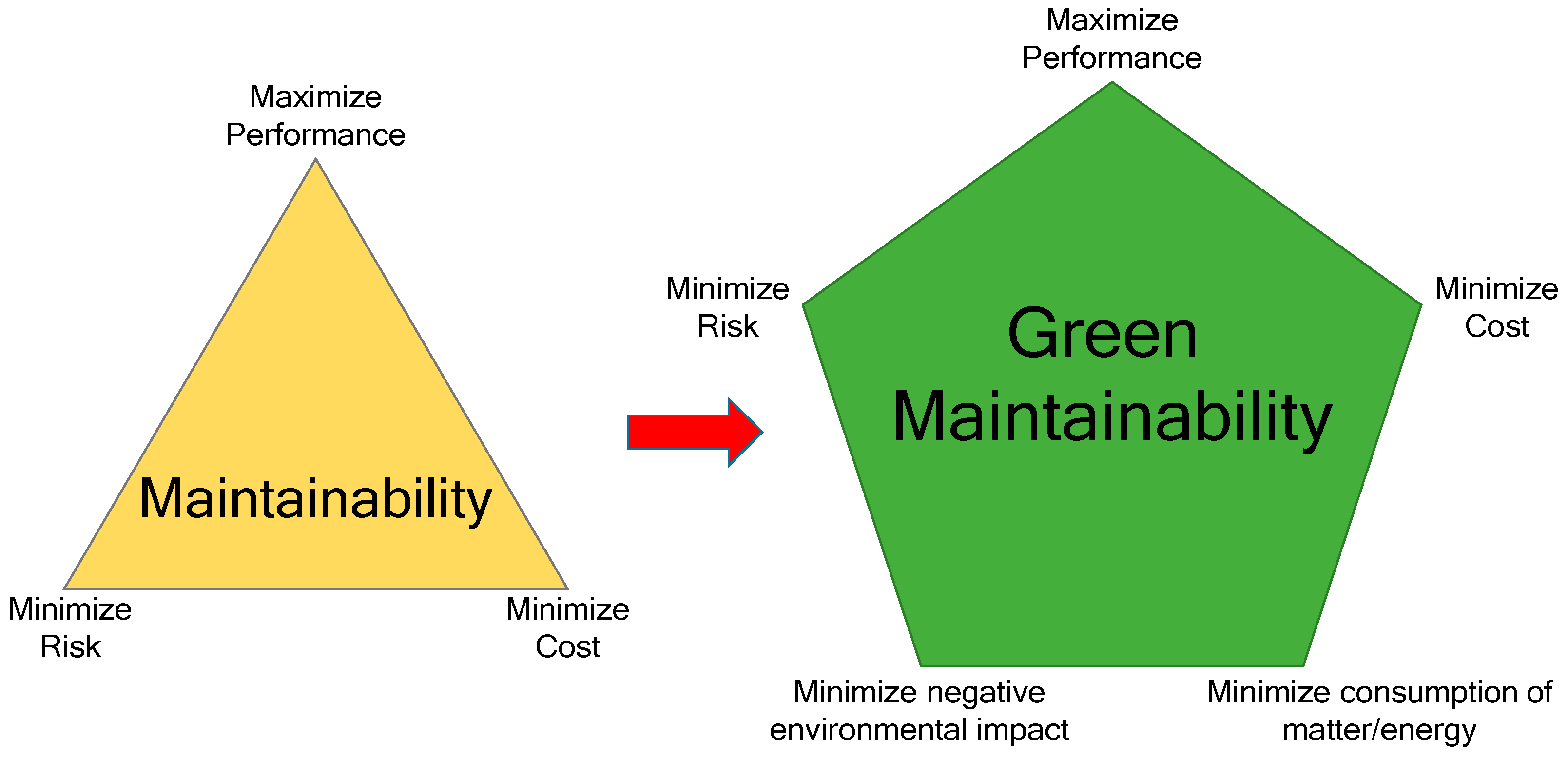
Maintainability is defined as the ability to achieve the optimum performance throughout the lifespan of a facility within the minimum life cycle cost.
Today, it is implicit that “design for maintainability” shall further consider sustainable design with an efficient use of resources and emphasis on environmental consciousness and practices. Termed as Green Maintainability, it requires considerations to maximise the performance and energy efficiency while minimising the total life cycle cost, embodied energy, environmental impact, and consumption of matter/energy throughout the life cycle of a facility, right from the planning/design stage (Figure 1) [1,2].
It has been shown that the lack of considerations on maintainability during the design and construction stages has led to building defects that account for the expenditure of billions of dollars throughout the building’s life cycle. More so, the potentially unsafe conditions of buildings can be detrimental to the lives and health of users. This raises the need to identify sources of defects with significant attention to design, detailing, materials, construction quality, and environmental factors at the outset. In order to improve the maintainability of buildings and to attain maintenance productivity over its lifetime, the underlying risk factors of buildings’ life cycle need to be identified and factored right from the planning/design stage.
The objectives of this study are as follows:
- To build upon existing maintainability research for Basements and Wet Areas by updating the existing databank and reviewing the state-of-the-art of regional and global counterparts in terms of standards and best practices with emphasis on ease of maintenance, productivity, labour efficiency, safety, and sustainability.
- To establish, develop, and verify critical indicators of facility design, construction, and maintenance on the outset of planning/design stage.
- To provide the basis for users to derive, customize, and validate their own stakeholder-based Maintainable Design Appraisal System (MDAS) at the outset, so as to enable a critical design for maintainability parameters for Basements and Wet Areas in terms of (i) ease of maintenance, (ii) productivity, (iii) labour efficiency, (iv) safety and (v) sustainability.
2. Materials and Methods
The state-of-the-art of regional and global counterparts in terms of standards and best practices were reviewed. Relevant global standards relating to maintainability factors (e.g., SS, BS, ISO, EN, AS, ASTM) were incorporated in the databank as the foundation phase for the creation of a viable and evidenced based appraisal system. The relevant international and national standards and best practices consulted for the study are listed at the end of the paper, after the “References”, under “Normative References/Standards” for Basements and Wet Areas, respectively.
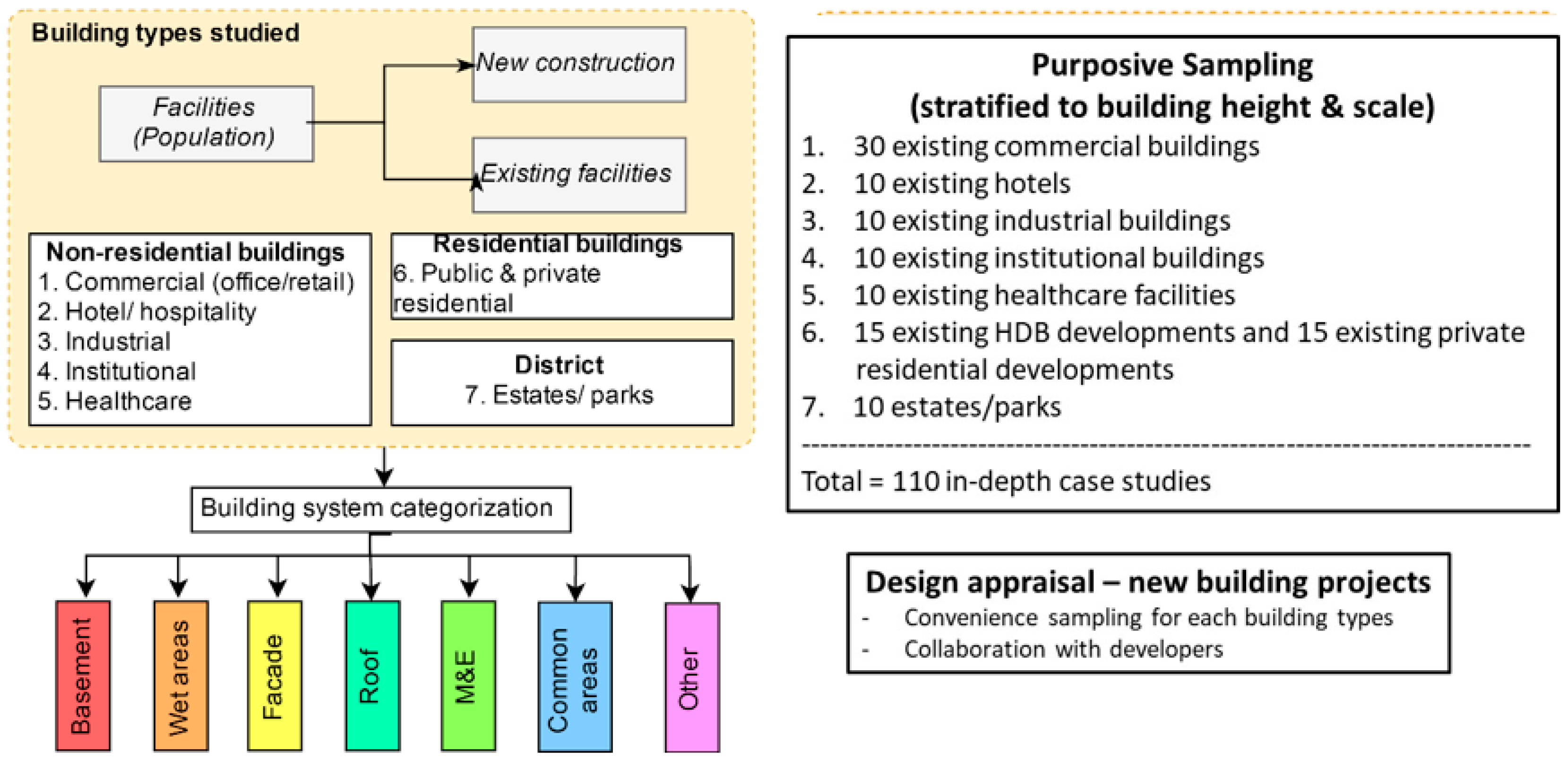
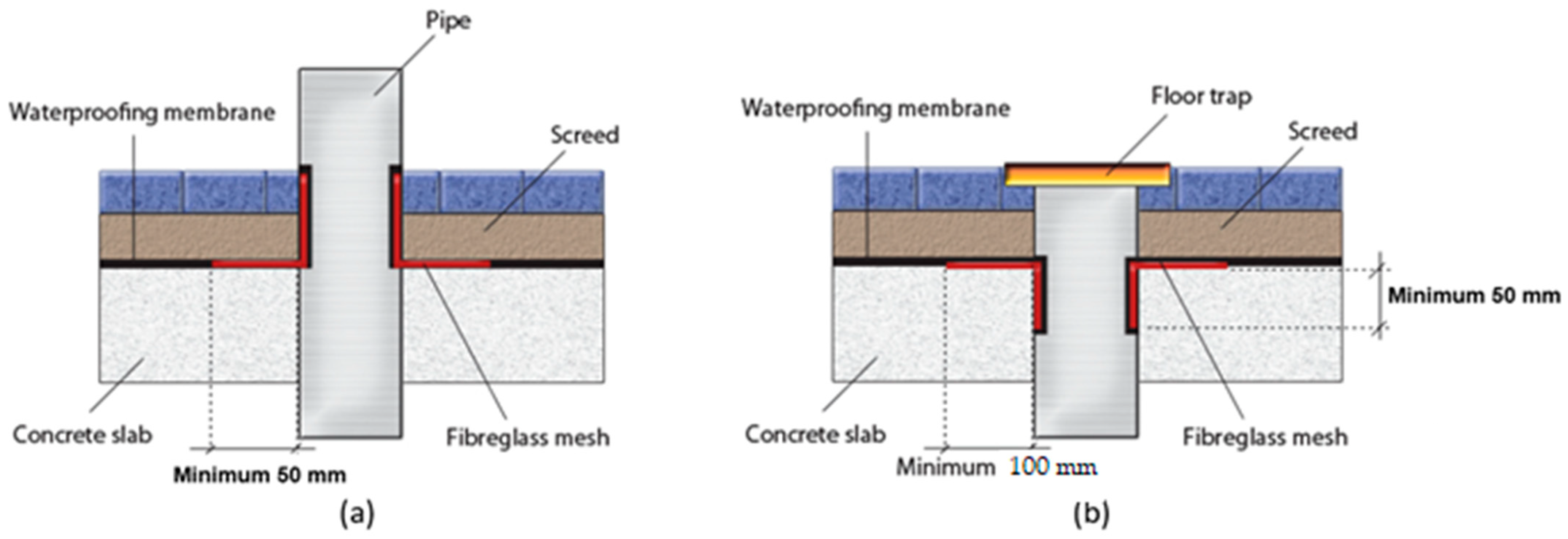
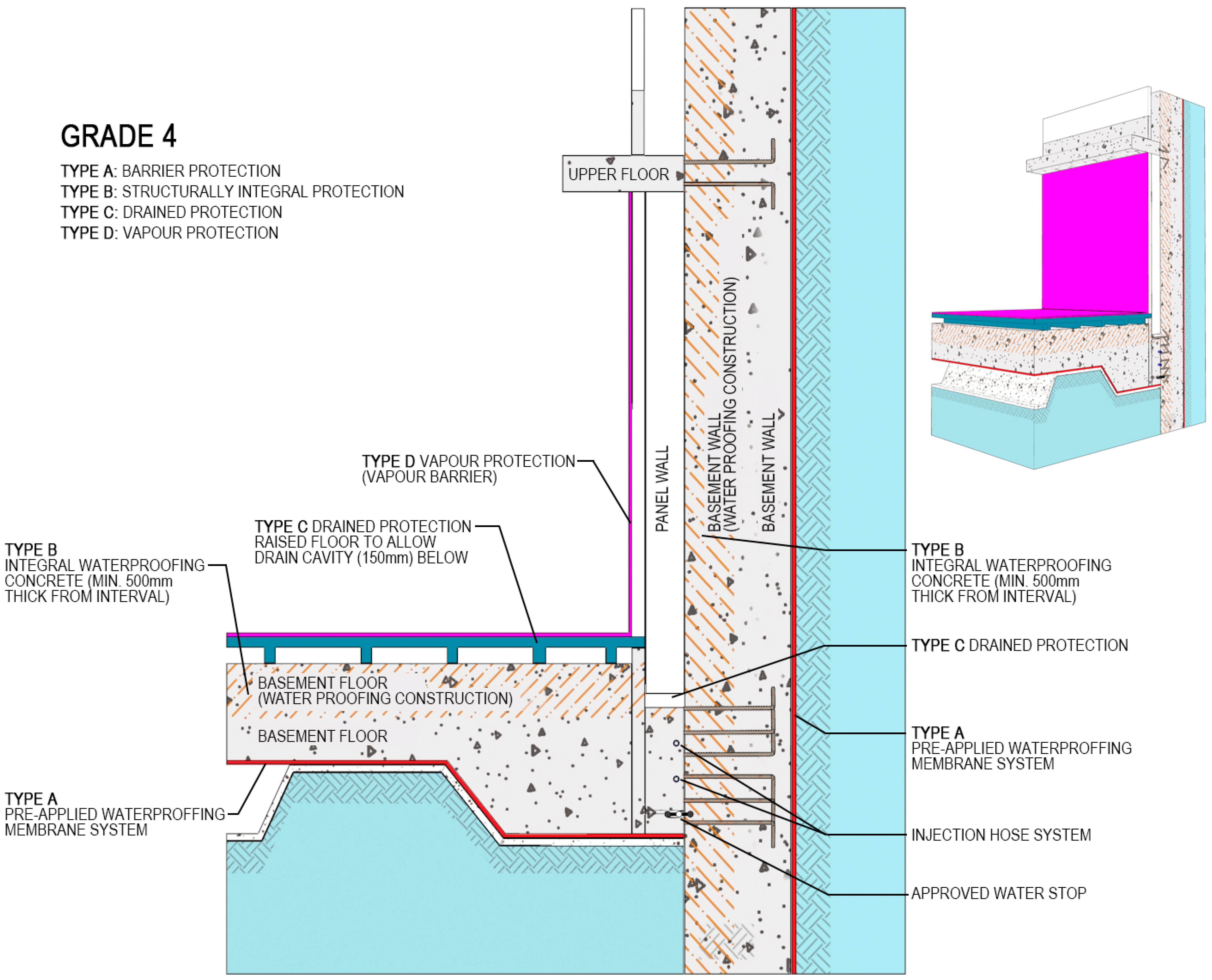
Case and field studies of commonly occurring problems in Basements and Wet Areas of a total of 110 buildings comprising of commercial, hotels, industrial, institutions, healthcare facilities, and residential facilities were conducted. The multiple case studies involved three major broad classifications of building types as non-residential buildings, residential buildings, and districts (estates/parks). Each of them was categorized into seven building components/system (e.g., basement, wet areas, facades, roof, M&E, common areas, and green technologies). The building types, building system categorization, samples, and sampling of buildings are shown in Figure 2. Typical configurations of Basements and Wet Areas investigated are the conventional types as shown in Figure 3 and Figure 4.
Factors considered in the study are shown in Table 1. Work studies were conducted on maintenance activities (i.e., cleaning, repair, and replacement) of different building systems for different building typologies. Work study in this regard is a systematic investigation of all factors affecting the efficiency and economy of maintenance activities with the prime aim of improving productivity. Both method studies and work measurement techniques such as time studies and activity sampling were used.
Face-to-face interviews and workshops with the respective professionals involved in the design, construction, and operation of the buildings were conducted for detailed investigation on each problem for their (a) problem types, (b) extent of problem, (c) failure mechanism, (d) good practices in design/construction/facilities management (FM) and (e) environmental issues.
3. Results
Anomalies were categorised and analysed according to types, locations, extents, frequencies, causes, and the roles of professionals. As the purpose of this paper is to provide easy-to-read tables of checklists based on a preventive/predictive performance-based approach, with defined acceptable standards in design, construction and operation and maintenance (O&M)/FM practices, results are shown in Table 2, Table 3 and Table 4 for Basements and Table 5, Table 6 and Table 7 for Wet Areas. Each table addresses the common defects and the corresponding design/construction/FM issues, with standards/guidelines/recommendations for the structural, architectural, and service components for Basement and Wet Areas, to be taken into account at the outset of the planning/design stage. For example, the “corrosion and spalling of concrete” in a basement is classified as a structural defect, which is highlighted with photographs taken from case studies, and the corresponding design, construction, and maintenance standards/guidelines to be considered at the outset of planning/design stage.
3.1. Basements
Table 2 shows the concerns for design, construction, and maintenance at the outset of the planning/design stage, for structural components e.g., floors, slabs, walls, and other load bearing and non-loading components.
Table 3 shows the concerns for design, construction and maintenance at the outset of the planning/design stage, for architectural components e.g., finishes, furnishings, and other elements that contribute to the aesthetic value and liveability.
Table 4 shows the concerns for design, construction, and maintenance at the outset of the planning/design stage, for service components that include vertical and horizontal circulation systems, electro-mechanical connections, and sanitary connections.
3.2. Wet Areas
Table 5 shows the concerns for design, construction, and maintenance at the outset of the planning/design stage, for structural components e.g., floors, slabs, walls, and other load-bearing and non-loading components.
Table 6 shows the concerns for design, construction, and maintenance at the outset of the planning/design stage, for architectural components e.g., finishes, furnishings, and other elements that contribute to the aesthetic value and liveability.
Table 7 shows the concerns for design, construction, and maintenance at the outset of the planning/design stage, for service components, which include vertical and horizontal circulation systems, electro-mechanical connections, and sanitary connections.
4. Discussion
The results showed that, common to both Basements and Wet Areas, most anomalies evaluated were associated with the following:
- (a)
- Inadequate provisions and details of the waterproofing membranes over discontinuities.
- (b)
- Inadequate provisions of the movement joints between structural elements.
- (c)
- Existence of a large number of discontinuities (penetrations).
- (d)
- Inadequate provisions for the drainage.
- (e)
- Poor planning and workmanship of application of the flooring, waterproofing membrane, and plumbing.
The results indicated that 11 factors were significant in causing seepage/leakages. They can be grouped as follows:
- Design factors
- Inappropriate waterproofing system adopted
- Lack of poor drainage design detailing
- Lack of waterproofing detailing
- Construction factors
- Insufficient compaction
- Improper installation of construction joints
- Improper installation of waterproofing
- Damage of waterproofing during construction
- Insufficient curing of waterproofing
- Maintenance factors
- Lack of regular inspection to detect defects
- Delayed repair to initial defect
- Deterioration of waterproofing
The evaluation of results are reflected in the checklist as shown in Table 2, Table 3, Table 4, Table 5, Table 6 and Table 7. The checklists may be used to assist professionals to synergise at the outset, the operational requirements and expected maintenance performance outcomes of a facility, with risk assessment adequately conducted at the planning/design stage. They also assist in the coordination among all professionals for accurate transfer of information throughout the complete delivery process to achieve high maintainability.
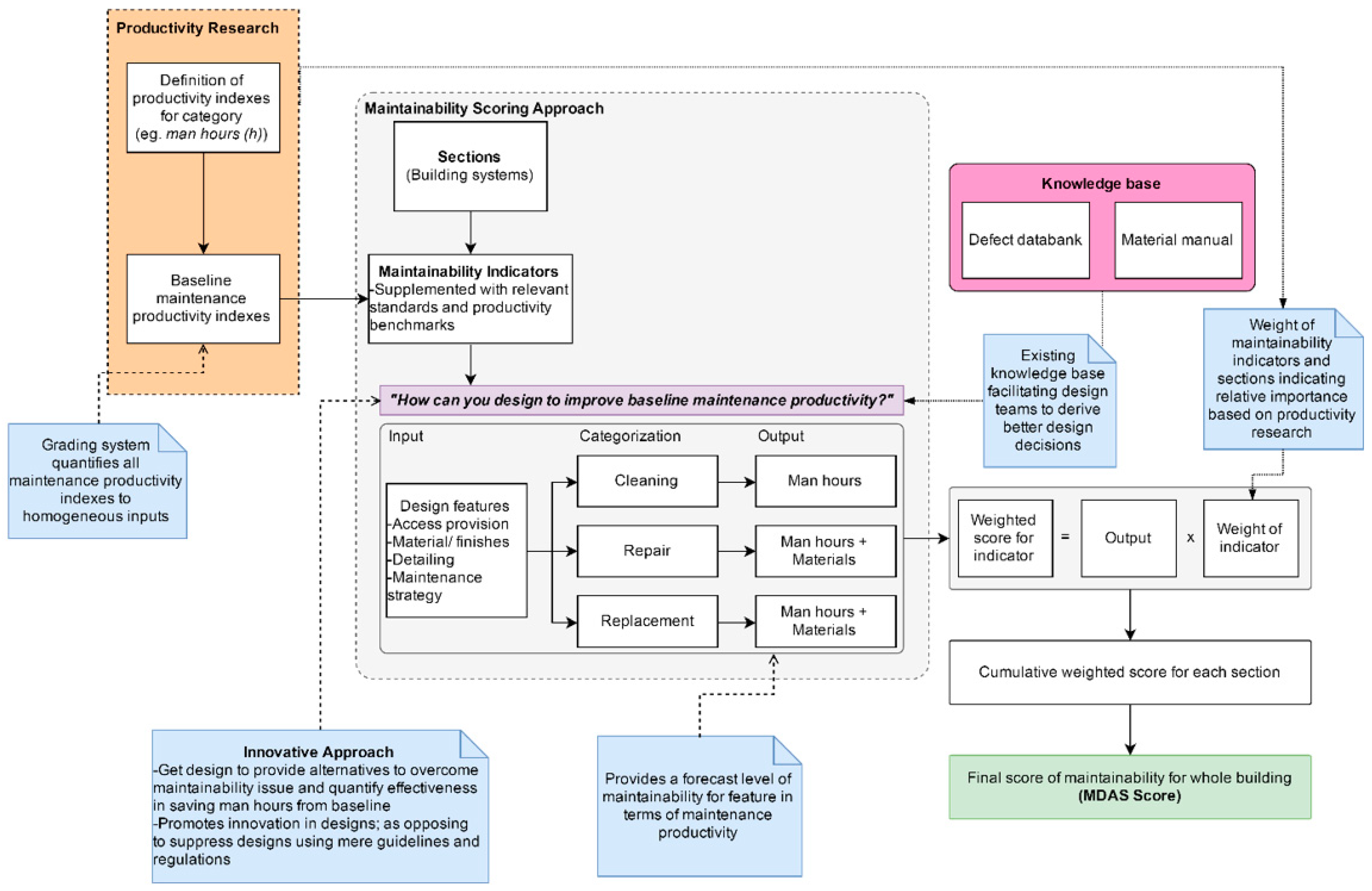
By selecting the appropriate clauses from the checklist, professionals may readily derive, customise, and validate their own Maintainable Design Appraisal System (MDAS) according to their specific needs, with assigned weighted additives for their criticality used to compute a cumulative MDAS score [25,26] signifying a realistic and effective indicator of maintainability. An example of one such formulation is illustrated in Figure 5.
Arising from the study, design, construction and O&M/FM teams are recommended to consider, at the outset of planning/design stage, the following.
4.1. Designs
In general, the following are recommended for the design team (including architect, M&E engineer, structural and civil engineer):
- (a)
- To consider the implications of design on future maintenance of the buildings and facilities, including considerations for access, cost effectiveness, and safe maintenance.
- (b)
- To provide a statement for complex or unique design features on how these special features should be maintained, including the access for maintenance.
- (c)
- To explore attributes of building materials, in order to specify the correct materials and building components for use in construction.
- (d)
- To consider the different M&E systems and its efficiency performance, in order to specify the correct systems for use in construction.
- (e)
- To alert owners or users on the impact of new materials and systems on future maintenance that are incorporated in the buildings and facilities.
- (f)
- To improve on the design and detailing of the buildings and facilities with a view to achieving maintainability but without sacrificing on the design.
- (g)
- To recommend the use of locally green-certified materials, especially interior products, for the better health and well-being of building occupants.
- (h)
- To consider the life cycle of the materials and products in accordance with the requirements of the owner.
- (i)
- To adopt advanced building information modelling techniques, such as soft clash detection using BIM, to ensure that clear access and sufficient headroom for M&E equipment is provided to facilitate future maintenance and replacement.
- (j)
- To consider designs that facilitate the adoption of technology to improve the efficiency of maintenance processes/works and to achieve the optimisation of building systems performance.
4.2. Construction
In general, the following are recommended for the construction team (including builder, sub-contractor, and supplier):
- (a)
- To focus on achieving good workmanship in construction to reduce defects and failures.
- (b)
- To ensure the proper and safe integration and coordination of different trades and elements during the construction.
- (c)
- To suggest more efficient design and to adopt more effective construction methods to achieve high maintainability.
- (d)
- To suggest the use of suitable materials to improve the maintainability of buildings and facilities.
- (e)
- To continually update the BIM model to ensure accuracy of the final model in synchronisation with actual as-built details.
4.3. Operation and Maintenance
In general, the following are recommended for the maintenance team (including facilities manager and property manager):
- (a)
- To promote proper and safe usage of buildings, systems, and plants.
- (b)
- To use correct equipment and tools in maintenance work.
- (c)
- To establish, when possible, a feedback loop to design and construction in the value chain by examining the gaps between design and maintenance, and construction and maintenance.
- (d)
- To consider the application of technology such as use of electronic devices to record and retrieve maintenance records and progress.
- (e)
- To consider the application of technology such as the use of robots to maintain difficult or inaccessible sites.
- (f)
- To undertake regular upkeep and maintenance by establishing effective maintenance programmes.
- (g)
- To engage owners, tenants, and occupiers in the maintenance programmes.
- (h)
- To consider the use of locally green-certified materials, especially interior products, for the better health and well-being of building occupants.
- (i)
- To consider technology adoption to:
- Reduce/optimise the manpower demand for maintenance works
- Improve the efficiency of maintenance processes/works
- Achieve the optimisation of building systems performance.
- (j)
- To adopt the necessary BIM data for asset management and potential integration with computerised maintenance management systems and/or building management systems to facilitate the automation and digitisation of maintenance works.
5. Conclusions
Results of data collected using case and field studies as well as face-to-face interviews on Basements and Wet Areas of a total of 110 buildings comprising of commercial, hotels, industrial, institutions, healthcare facilities, and residential facilities were evaluated. From these, we derived easy-to-read tables of checklists based on a preventive/predictive performance-based approach, which define acceptable standards in design, construction, and O&M/FM practices. The critical indicators for design, construction, operation, and maintenance of facilities for basements and wet areas were presented. This study provides information for building and real estate professionals involved in the design, construction, and operation of a facility by:
- Enhancing the high maintainability of facilities through identifying the common maintainability issues and corresponding requirements for designers, constructors, and facilities managers at the outset of the planning/design stage.
- Recommending best practices for the respective professionals from design, construction, to operation/maintenance stages, in a practical, concerted, and conscientious manner towards high maintainability, safety, productivity, and environmentally friendly goals.
- Inculcate a conscious effort and commitment for all building and real estate professionals to take into consideration the whole life performance and economic value of a facility within the environmental constraints.
With the results from the evidence-based empirical studies conducted, the development and validation of the stakeholder-based appraisal system (MDAS) could be customised by users with assigned weighted additives for their criticality used to compute a cumulative MDAS score signifying a realistic and effective indicator of maintainability for their properties.
| Normative References/Standards Referred to for Basements in Table 2, Table 3 and Table 4 | |
| ASTM C1193-16 | Standard Guide for Use of Joint Sealants |
| ASTM C33/C33M-16e1 | Standard Specification for Concrete Aggregates |
| BS 1881-210 | Testing hardened concrete. Determination of the potential carbonation resistance of concrete. Accelerated carbonation method |
| BS 6093 | Design of joints and jointing in building construction. Guide |
| BS 6150 | Painting of buildings. Code of practice |
| BS 6213 | Selection of construction sealants. Guide |
| BS 6398 | Specification for bitumen damp-proof courses for masonry |
| BS 8000-0 | Workmanship on construction sites. Introduction and general principles |
| BS 8004 | Code of practice for foundations |
| BS 8102 | Code of practice for protection of below ground structures against water from the ground |
| BS 8204-1 | Screeds, bases and in situ floorings. Concrete bases and cementitious levelling screeds to receive floorings. Code of practice |
| BS 8204-2 | Screeds, bases and in situ floorings. Concrete wearing surfaces. Code of practice |
| BS 8210 | Guide to facilities maintenance management |
| BS 8215 | Code of practice for design and installation of damp-proof courses in masonry construction |
| BS EN 12845 | Fixed firefighting systems. Automatic sprinkler systems. Design, installation and maintenance |
| BS EN 13139 | Aggregates for mortar |
| BS EN 14630 | Products and systems for the protection and repair of concrete structures. Test methods. Determination of carbonation depth in hardened concrete by the phenolphthalein method |
| BS EN 1504-2 | Products and systems for the protection and repair of concrete structures. Definitions, requirements, quality control and evaluation of conformity. Surface protection systems for concrete |
| BS EN 1504-3 | Products and systems for the protection and repair of concrete structures. Definitions, requirements, quality control and evaluation of conformity. Structural and non-structural repair |
| BS EN 1504-5 | Products and systems for the protection and repair of concrete structures. Definitions, requirements, quality control and evaluation of conformity. Concrete injection |
| BS EN 1504-9 | Products and systems for the protection and repair of concrete structures. Definitions, requirements, quality control and evaluation of conformity. General principles for use of products and systems |
| BS EN 1992-1-1 | Eurocode 2: Design of concrete structures. General rules and rules for buildings |
| BS EN 1992-1-2 | Eurocode 2. Design of concrete structures. General rules. Structural fire design |
| BS EN 1992-3 | Eurocode 2. Design of concrete structures. Liquid retaining and containing structures |
| BS EN 752 | Drain and sewer systems outside buildings. Sewer system management |
| BS EN ISO 11600 | Building construction. Jointing products. Classification and requirements for sealants |
| CP 4 | Code of practice for foundations |
| CP 52 | Code of practice for automatic fire sprinkler system |
| CP 65-1 | Code of practice for structural use of concrete—Design and construction |
| EN 1997 | Geotechnical design |
| SS 150 | Specification for emulsion paint for decorative purposes |
| SS 509-1 | Code of practice for cleaning and surface repair of buildings—Part 1: Cleaning of natural stone, brick, terracotta, concrete and rendered finishes |
| SS 542 | Code of practice for painting of buildings |
| SS 608 | Code of practice for gas installation |
| SS 637 (formerly CP 82) | Code of practice for waterproofing of reinforced concrete buildings |
| SS EN 12620 | Specification for aggregates for concrete |
| SS EN 1992-1-1 | Eurocode 2: Design of concrete structures, Part 1.1 General rules and rules for buildings |
| SS EN 1992-1-2 | Eurocode 2: Design of concrete structures, Part 1.2 General rules—Structural fire design |
| Normative References/Standards Referred to for Wet Areas in Table 5, Table 6 and Table 7 | |
| ANSI A118.15 | American National Standard Specifications for Improved Modified Dry-Set Cement Mortar (improved modified mortar) |
| AS 3740 | Waterproofing of domestic wet areas |
| ASTM C1400-11 | Standard Guide for Reduction of Efflorescence Potential in New Masonry Walls |
| BS 5385-1 | Wall and floor tiling. Design and installation of ceramic, natural stone and mosaic wall tiling in normal internal conditions. Code of practice |
| BS 5385-3 | Wall and floor tiling. Design and installation of internal and external ceramic and mosaic floor tiling in normal conditions. Code of practice |
| BS 6093 | Design of joints and jointing in building construction. Guide |
| BS 6150 | Painting of buildings. Code of practice |
| BS 6270-3 | Code of practice for cleaning and surface repair of buildings. Metals (cleaning only) |
| BS 8000-0 | Workmanship on construction sites. Introduction and general principles |
| BS 8000-11 | Workmanship on building sites. Internal and external wall and floor tiling. Ceramic and agglomerated stone tiles, natural stone and terrazzo tiles and slabs, and mosaics. Code of practice |
| BS 8000-9 | Workmanship on building sites. Cementitious levelling screeds and wearing screeds. Code of practice |
| BS 812-109 | Testing aggregates. Methods for determination of moisture content |
| BS 8204-1 | Screeds, bases and in situ floorings. Concrete bases and cementitious levelling screeds to receive floorings. Code of practice |
| BS 8204-2 | Screeds, bases and in situ floorings. Concrete wearing surfaces. Code of practice |
| BS 8210 | Guide to facilities maintenance management |
| BS 8215 | Code of practice for design and installation of damp-proof courses in masonry construction |
| BS 8221-1 | Code of practice for cleaning and surface repair of buildings. Cleaning of natural stone, brick, terracotta and concrete |
| BS 8221-2 | Code of practice for cleaning and surface repair of buildings. Surface repair of natural stones, brick and terracotta |
| BS 8542 | Calculating domestic water consumption in non-domestic buildings. Code of practice |
| BS 8554 | Code of practice for the sampling and monitoring of hot and cold water services in buildings |
| BS 8595 | Code of practice for the selection of water reuse systems |
| BS EN 12004-1 | Adhesives for ceramic tiles. Requirements, assessment and verification of constancy of performance, classification and marking |
| BS EN 12056-2 | Gravity drainage systems inside buildings. Sanitary pipework, layout and calculation |
| BS EN 1504-5 | Products and systems for the protection and repair of concrete structures. Definitions, requirements, quality control and evaluation of conformity. Concrete injection |
| BS EN 1992-1-1 | Eurocode 2: Design of concrete structures. General rules and rules for buildings |
| BS EN 1992-3 | Eurocode 2. Design of concrete structures. Liquid retaining and containing structures |
| BS EN 771-1 | Specification for masonry units. Clay masonry units |
| BS EN ISO 12944-4 | Paints and varnishes. Corrosion protection of steel structures by protective paint systems. Types of surface and surface preparation |
| BS EN ISO 1513 | Paints and varnishes. Examination and preparation of test samples |
| BS ISO 10880 | Non-destructive testing. Infrared thermographic testing. General principles |
| CP 68 | Code of practice for ceramic wall and floor tiling |
| ISO 10545-1 | Ceramic tiles—Part 1: Sampling and basis for acceptance |
| ISO 13006 | Ceramic tiles—Definitions, classification, characteristics and marking |
| ISO 13007-1 | Ceramic tiles—Grouts and adhesives—Part 1: Terms, definitions and specifications for adhesives |
| ISO 13007-5 | Ceramic tiles—Grouts and adhesives—Part 5: Requirements, test methods, evaluation of conformity, classification and designation of liquid-applied waterproofing membranes for use beneath ceramic tiling bonded with adhesives |
| ISO 28841 | Guidelines for simplified seismic assessment and rehabilitation of concrete buildings |
| ISO 4356 | Bases for the design of structures—Deformations of buildings at the serviceability limit states |
| SS 509-1 | Code of practice for cleaning and surface repair of buildings—Part 1: Cleaning of natural stone, brick, terracotta, concrete and rendered finishes |
| SS 509-2 | Code of practice for cleaning and surface repair of buildings—Surface repair of natural stones, brick, terracotta and rendered finishes |
| SS 542 | Code of practice for painting of buildings |
| SS 637 (formerly CP 82) | Code of practice for waterproofing of reinforced concrete buildings |
| SS EN 1992-1-1 | Eurocode 2: Design of concrete structures, Part 1.1 General rules and rules for buildings |
| SS EN 934-2 | Admixtures for concrete, mortar and grout—Part 2: Definitions, requirements—Concrete admixtures—Definitions, requirements, conformity, marking and labelling |
Funding
This research received no external funding.
Institutional Review Board Statement
Not applicable.
Informed Consent Statement
Not applicable.
Data Availability Statement
Not applicable.
Conflicts of Interest
The author declares no conflict of interest.
References
- Chew, M.Y.L. Maintainability of Facilities—Green FM for Building Professionals, 2nd ed.; World Scientific: Singapore, 2016. [Google Scholar]
- Chew, M.Y.L.; Ashan, A.; Conejos, S. Design for Maintainability; World Scientific: Singapore, 2018. [Google Scholar]
- Building and Construction Authority. Waterproofing for Internal Wet Areas, 2nd ed.; Building and Construction Authority (BCA): Singapore, 2003.
- Public Utilities Board. Code of Practice on Surface Water Drainage; Public Utilities Board (PUB): Singapore, 2013.
- Public Utilities Board. Flood Protection Measures, Flood Management. 2016. Available online: www.pub.gov.sg/drainage/floodmanagement/floodprotectionmeasures (accessed on 26 January 2021).
- Public Utilities Board. Managing Urban Runoff—Drainage Handbook, 1st ed.; Public Utilities Board (PUB): Singapore, 2013.
- Building and Construction Authority. Good Industry Practices—Waterproofing for External Wall, 2nd ed.; Building and Construction Authority (BCA): Singapore, 2004.
- Building and Construction Authority. CONQUAS® The BCA Construction Quality Assessment System, 9th ed.; Building and Construction Authority (BCA): Singapore, 2017.
- Land Transport Authority. Materials and Workmanship Specification for Architectural Work; Land Transport Authority (LTA): Singapore, 2009.
- Singapore Green Building Council Green Certification for Products. Available online: www.sgbc.sg (accessed on 26 January 2021).
- Public Utilities Board. Code of Practice on Surface Water Drainage, 7th ed.; Public Utilities Board (PUB): Singapore, 2018.
- Land Transport Authority. Civil Design Criteria; Land Transport Authority (LTA): Singapore, 2010.
- Building and Construction Authority. Precast Concrete Elements; Building and Construction Authority (BCA): Singapore, 2006.
- Housing and Development Board. Ceiling Leaks, Home Care Guide. 2017. Available online: www.hdb.gov.sg/cs/infoweb/residential/living-in-an-hdb-flat/home-maintenance/ceiling-leaks (accessed on 22 January 2021).
- Housing and Development Board. Spalling Concrete; Home Care Guide; Housing and Development Board (HDB): Singapore, 2017.
- Building and Construction Authority. Good Industry Practices—Painting, 2nd ed.; Building and Construction Authority (BCA): Singapore, 2004.
- Building and Construction Authority. Design and Material Selection for Quality; Building and Construction Authority (BCA): Singapore, 2009; Volume 2.
- Building and Construction Authority. Marble & Granite Finishes, 2nd ed.; Building and Construction Authority (BCA): Singapore, 2003.
- Building and Construction Authority. Ceramic Tiling, 2nd ed.; Building and Construction Authority (BCA): Singapore, 2003.
- Building and Construction Authority. Design and Material Selection for Quality; Building and Construction Authority (BCA): Singapore, 2008; Volume 1.
- Public Utilities Board. Plumbing Works. Water Supply. 2016. Available online: https://www.pub.gov.sg/watersupply/plumbingworks (accessed on 22 March 2017).
- Building and Construction Authority. Prefabricated Bathroom Unit (PBU); Building and Construction Authority (BCA): Singapore, 2014.
- Restroom Association. A Guide to Better Public Toilet Design and Maintenance, 3rd ed.; Restroom Association: Singapore, 2013. [Google Scholar]
- Public Utilities Board. Code of Practice on Sewerage and Sanitary Works, 2nd ed.; Public Utilities Board (PUB): Singapore, 2019.
- Chew, M.Y.L.; Egodage, N.D.D.S.; Tan, S.S. A neural network approach to assessing building facade maintainability in the tropics. Constr. Manag. Econ. 2004, 22, 581–594. [Google Scholar] [CrossRef]
- Chew, M.Y.L.; Egodage, N.D.D.S. Factorial Method for Performance Assessment of Building Facades. J. Constr. Eng. Manag. 2004, 130, 525–533. [Google Scholar] [CrossRef]
Figure 1.
Definitions of maintainability and Green Maintainability.

Figure 2.
Case building selection and sampling.

Figure 3.
Conventional Wet Area waterproofing details at (a) pipe penetrations and (b) floor traps.

Figure 4.
Conventional Basement wall and floor configuration with waterproofing details for Types A to D.
Figure 4.
Conventional Basement wall and floor configuration with waterproofing details for Types A to D.

Figure 5.
Formulation of the Maintainable Design Appraisal System (MDAS).


Table 1.
Factors considered for case and field studies.
| Element | Basement | Wet Areas |
|---|---|---|
| Structural | Corrosion/spalling of concrete Seepage through cracks Seepage through porous concrete Flood control | Seepage through structural joints Leakage through concrete slab Leakage through cracks and porous walls/floors Corrosion and spalling of concrete |
| Architectural | Proper installation of construction joints Seepage through joints Water ponding Waterproofing Wall finishes Flooring | Efflorescence Biological stains Paint Tile interface with other elements Tile cracks Tile staining Tile joints Floor gradient and screed Waterproofing |
| Services | Drainage Penetration for services Pumped drainage system Gas installation | Accessibility Penetrations for sanitary fittings Fixture and fittings Gas installation |
Table 2.
Basements—Structural components e.g., floors, slabs, walls and other load-bearing and non-loading components.
Table 2.
Basements—Structural components e.g., floors, slabs, walls and other load-bearing and non-loading components.
| Anomaly | Design | Construction | Maintenance |
|---|---|---|---|
Corrosion/spalling of concrete Spalled concrete and corrosion of exposed rebars  Extreme spalling and corrosion of basement | Adopt SS EN 1992-1-1, SS EN 1992-1-2, CP 65-1, or equivalent for the design of concrete. Specify admixtures (e.g., water-reducing agent, pozzolanic products, pore refiner, etc.) to reduce permeability. Consider galvanised reinforcing steel in high-corrosive areas in accordance with BS EN 10348-2:2018. Alternatively, for corrosion control in special areas with a high risk of water penetration, an electrochemical treatment can be specified; a process where the electrochemical drying of concrete occurs by passing a current through the reinforcement, which is similar in principle to cathodic protection in accordance with BS EN 1504-9 or equivalent. | For the construction of basements, refer to the guidelines and provisions stipulated in CP 4, BS 8004, EN 1997 or equivalent. Maintain water–cement ratio and the recommended aggregate grading during basement construction. Verify aggregate quality in accordance with ASTM C33/C33M-16e1 or equivalent. Use corrosion-resistant bars and corrosion inhibitors. Apply proper vibration (compaction) and curing. Consider concrete sealing to avoid exposing the aggregate in concrete work (mitigate pitting, scaling, spalling, powdering, or chalking of concrete). | Regular inspection should be carried out in accordance to BS 8210 to identify defects and ensure repair work is carried out before associated damage can occur. Testing of concrete via depth of carbonation should be carried out to identify possible corrosion of rebar in accordance with BS 1881-210 or via phenolphthalein method in accordance with BS EN 14630 or equivalent. Damaged concrete due to corrosion of reinforcing steel should be repaired and protected in accordance with BS EN 1504-9 or equivalent. |
Seepage through cracks Water stains and efflorescence along crack lines  Water ponding and subsequent rising dampness on the wall  Water seepage and efflorescence along crack lines | Adopt SS EN 1992-1-1 or equivalent for surface cracks (caused by applied loads, or thermal and shrinkage effects). Surface cracks should not exceed width of 0.3 mm. Provide rebar layout to facilitate vibrations/compactions. Adopt BS EN 1992 or equivalent for water resistance (a primary design concern) as seepage through cracks in structural elements is unacceptable for basements. Provide waterproofing with reinforced concrete design in accordance with BS EN1992-1-1 and BS EN 1992-3 or equivalent for crack prohibition at stress concentrated areas (e.g., joints, interfaces). | Installation of waterproofing in accordance with BS 8102 and SS 637or equivalent. Careful supervision of all stages of construction. Construct for waterproofing with due understanding of site conditions and construction method in accordance with BS 8102 or equivalent. Special considerations on stress-concentrated areas such as joints and interfaces between different materials. A crack width limit of 0.2 mm normally applies to all cracks, irrespective of whether or not they pass completely through the section. Where the appearance of a structure is considered to be aesthetically critical, a limit of 0.1 mm is recommended in accordance with BS EN 1992-3 or equivalent. | Routine inspection should be carried out of basement areas for visible signs of water seepage such as efflorescence, especially at high-risk areas such as joints and pipe penetrations. Protect against ingress and increase moisture resistance with hydrophobic impregnation and/or coating in accordance with BS EN 1504-2, or filling of cracks in accordance with BS EN 1504-5. Concrete restoration with hand-applied mortar, recasting, or spraying with concrete/mortar in accordance with BS EN 1504-3. Restoring passivity by for example, increasing cover with additional mortar/concrete, replace contaminated or carbonated concrete in accordance with BS EN 1504-3. |
Seepage through porous concrete Efflorescence and water stains due to seepage | Monolithic basement construction (wall/floor) is required for water-tightness. Specify the proper waterproofing with suitable material and consider aggressive conditions and proper mix design in accordance with BS 8102 and SS 637 or equivalent. | For quality workmanship, adopt the recommended curing process; ensure sufficient reinforcement cover; and proper vibration (for well compacted mortar) of concrete to avoid honeycombs in accordance with CONQUAS 21 recommendations [3]. | Conduct regular inspections of basement area in accordance with BS8210. Repair identified seepage defects by injecting cracks, voids, or interstices in accordance with EN 1504-5. Enforce a full recorded survey of condition before problems are hidden below patch repairs, coatings, or waterproofing in accordance with BS EN 1504-9. |
Flood Control Flooded mall underpass  Flooded basement parking  Flood Barrier (left: not activated, right: activated) [4] | For basements in water-bearing soils, ensure that the upward water pressure is uniform below the whole area of the floor. It must be capable of resisting the total pressure less the weight of the floor. The walls should be designed to resist the horizontal pressures due to the waterlogged ground and prevent the basement from flooding in accordance with BS 8004, EN 1997 or equivalent. Provide design features to protect basements against flood risks with crest level for entrance, exit, or opening to basement and pumped drainage system [5]. Implement flood protection measures (e.g., humps and flood barriers) to protect basement from floodwaters, link water-level sensors in the basement carparks to building’s alarm systems to warn users of flooding and preparation of standby sand bags and flood boards for buildings located in low-lying areas [4,6]. | During construction, ensure that there is always an excess of downward load to exceed the worst credible upward force due to the water by a substantial margin in accordance with BS 8004, EN1997, or equivalent. Permanent deep basement structures create permanent change in ground water patterns when its dead load exceeds the total upward force on the structure. During construction, the level of groundwater near the basement needs to be controlled by pumping or other means. Consider methods such as open pumping, pre-drainage, cut-offs, or exclusion. Water that has infiltrated the building due to structural porosity needs to be drained using dedicated pipes to sumps and subsequent pumping. | Check and confirm by inspection and testing for any deviations from as-built drawings; any indications of defective or substandard construction; indications of severe local environments from ponding, waterproofing breakdown, and seepage; and for the current trends of deterioration and likely long-term trends in accordance with BS EN 1504-9. Carry out periodic inspection for ponding and make visual observations of free flowing water towards the outlets to ensure that water has drained off, so as to avoid leftover ponding on reinforced concrete in accordance with BS 8221-1, SS 509-1, or equivalent. Monitor basement carpark water-level using sensors and warn building users in a timely manner [5]. |
Table 3.
Basements—Architectural components e.g., finishes, furnishings, and other elements that contribute to the aesthetic value and liveability.
Table 3.
Basements—Architectural components e.g., finishes, furnishings, and other elements that contribute to the aesthetic value and liveability.
| Anomaly | Design | Construction | Maintenance |
|---|---|---|---|
Proper installation of construction joints Water seepage through joint  Chemical injection at a wall-to-ceiling construction joint  Cracks along joints, and joint sealants need replacing | Specify the use of expansion joints where effects of temperature and moisture are too large to absorb as a strain in order to separate framed structures from joints’ sections in accordance with BS 6093 or equivalent. Refer to the selection and specification of sealants in accordance with BS 6213 or equivalent. Refer to BS EN ISO 11600 for a systematic performance classification scheme for sealants applied in building and construction. Provide internal/external water-stops to accommodate differential movements (flanges of water-stops tied to RF in adequate intervals). | Seal construction joints to withstand multi-directional stresses. Ensure proper installation of water-stops. Adoption of pure bentonite water-stop is recommended, since it can seal capillary cracks in the cold joint. Provide proper surface preparation for the installation of sealants and gaskets (ensure that gaskets should not be stretched during installation) in accordance with BS 6093 or equivalent. Slow down the drying of concrete to avoid plastic shrinkage and provide joints/planes of weakness to confine cracking to determined positions in accordance with BS 6093 or equivalent. Change joint gap width from the time of erection to sealing. Hence, the best time for sealant application in movement joints is when the joint gap is at the mean trending to the maximum in accordance with BS 6093 or equivalent. | Carry out visual inspection on the integrity of the joints in accordance with BS 8102, SS 637, or equivalent. Use non-destructive field diagnostic techniques to identify seepage through joints where visual inspection is not sufficient (e.g., infrared thermography for moisture detection, portable microwave tomography to identify source of leakage). Replace old sealant with a suitable one in accordance with ASTM C1193-16. Inspect joints at intervals equivalent to one-fifth of their expected life (additionally, all joints subject to movement be inspected for signs of premature failure after first year in service) in accordance with BS 6093. |
Seepage through joints Water seepage through joint interfaces  Algae and water stains at joints  Efflorescence, water stains, and mould growth at joints | Specify proper sealant design at joints to prevent seepage caused by differential movements in accordance with BS EN 15651-3, SS 637, or equivalent. Water penetration is prevented by incorporating sealants, sealing strips, gaskets, and baffles in accordance with BS 8102 or equivalent. Conventional sealants typically have +/− 25% joint movement and sealants are not meant for joint width greater than 25 mm. Provide comprehensive design detailing of joints to avoid the promotion of mould and plant growth; discolouration due to UV radiation and biological, physical, or chemical action; showing of internal structure (in part or all); and dust collection in accordance with BS 6093 or equivalent. Consider fit-for-immersion sealant for horizontal joint. Sealant designed for immersion should typically be able to mitigate mould growth. | The use of wet joints is essential in minimising water seepage through joint areas. Ensure its proper installation with suitable backer rod and sealant application [7]. For vertical joints, a baffle provides the overlapping needed to stop water seepage. The baffle needs to extend beyond the groove and not shorten due to creep in accordance with BS 6093 or equivalent. | Routine visual inspections should be carried out of joints and look for tell-tale signs of water seepage in basement areas (e.g., deteriorated or damaged wall/floor/ceiling material, biological growth). If seepage through joints is suspected, non-destructive tests should be carried out to assist with the identification of the sources of water. A water-spraying test should be carried out at the precast joints to check for water-tightness in accordance with BS 8102:2009, SS 637, or equivalent. |
Water ponding Water ponding in a basement | Adopt proper drainage design (slope/outlet) [7,8]. Adopt the proper compaction of ground/soil to maintain even settlement in accordance with BS 8004, EN 1997, CP 4, or equivalent. It is presupposed that the requirements in basement construction are in compliance with applicable statutory and regulatory requirements [5]. | Perform proper leveling of floor surface to avoid ponding in falls for wet area [8]. Establish full specification and procedure for repair, propping, testing, and handing over with the as-built drawings [9]. | Periodic inspection should be carried out for ponding and make visual observations of free-flowing water towards the outlets. Ensure that water has drained off to avoid leftover ponding on the reinforced concrete. Drains should be inspected for efficiency prior to water washing in accordance with (BS 8221-1, SS 509-1, or equivalent. |
Waterproofing Seepage through slab and wall due to poor waterproofing  Water seepage due to poor waterproofing  Example of Type A waterproofing system  Example of Type B waterproofing system  Example of Type C waterproofing system | Minimise wall joints in wet areas. Kerbs to be constructed at the base of walls to halt lateral movement of water. Basement masonry structure is not recommended. Select waterproofing types A, B, or C or a combination of them, depending on the performance requirements of usage cases in accordance with BS 8102, SS 637, or equivalent. Adopt the use of damp-proof courses in accordance with BS 6398, BS 8215, or equivalent. Review architectural, structural, and M&E coordination drawings of affected wet areas together to ensure proper integration and reliability of waterproofing system. Provide proper design for adequate drop of cast concrete to maintain floor gradient and to prevent water from migrating to the dry area. A screed should be laid over the membrane as a protective measure and sloped towards the floor outlet. | Ensure proper surface preparation of concrete using mechanical or chemical cleaning. Ensure that the substrate is dry, so as to avoid blistering of non-breathing waterproofing material. Consider using waterproofing product by compression method that is not moisture sensitive. Allow for good ventilation and check with a moisture meter. Conversely, pre-saturate substrate if cementitious membrane systems are used for improved adhesion. Use of continuous angle fillet (25 mm × 25 mm, 1:3 cement sand with 1:4 bonding agent and water) for membrane to lay gradually over internal corners and floor–wall joints. Mix waterproofing products (preferably green certified) [10] in accordance with manufacturer’s specifications in a controlled environment. Application is also in accordance with manufacturer’s specifications. Take protective measures into consideration to prevent the waterproofing membrane from damage by any activities on site (e.g., by use of Styrofoam) in accordance with BS 8102, CP 82, or equivalent. | Concrete surface cleaning and repair applications of a continuous waterproofing barrier system should be carried out in accordance with BS 8102, SS 637, or equivalent. Precautions should be taken to avoid leaks. Any joints suspected or confirmed to be leaking should receive immediate attention, as delay can cause extensive damage. Proper insulation should be provided for all external and exposed piping in accordance with BS 8210. |
Wall finishes—Paint Blistering and efflorescence  Peeling and flaking of paint  Paint peeling on wall | Specify the use of a local green certified breathable paint system to reduce trapped moisture and to avoid wetness and dampness of basement walls. Fungi-resistant paint is recommended. Avoid the use of alkyd-based paint on concrete surfaces that may lead to saponification (i.e., the formation of oily patches) in accordance with BS EN 1504-2 or equivalent. | Ensure adequate curing of substrate before paint application to avoid shrinkage cracks. Permissible moisture content should refer to paint manufacturer’s recommendation. Clean surface and use clean tools. Avoid prolonged storing, inadequate stirring, use of incompatible thinner/solvent, or mixing with leftover paints from previous batches in accordance with BS 6150 and SS 542 or equivalent. If it is brush-applied, apply the second coat at right angles to the first coat to help eliminate pinholes and avoid chemical attacks in accordance with BS 8000-0 and SS 150 or equivalent. Ensure that coatings, preferably locally green certified are always applied in a minimum of three coats. The material should possess some degree of flexibility (i.e., be elastomeric) to reduce the risk of cracking due to thermal/moisture in accordance with BS8000-0, SS 150, SS 542, SS554, or equivalent. | Inspection should be done annually to ensure the buildings are in good condition and to identify necessary repairs in accordance with BS 6150, SS 542, or equivalent. Walls that are lightly soiled should be washed with water and a mild detergent. For severe soiling, wash with a strong alkali solution in warm water. The walls should be re-painted regularly. Repair hairline cracks by re-painting the wall with a flexible sealant/elastomeric paint to seal the cracks. For wider cracks, engage a contractor to carry out repair works. |
Flooring Damp/dirt stain  Water mark and moulds along column joint  Floor stains  Basement floor cracks | Ensure the design works as a monolithic unit to comply with requirements for durability, strength, dimensional stability, resistance to wear, slip, and dampness in accordance with BS EN 8204-2 or equivalent. Specify type of additives to use (e.g., air-entraining superplasticising, set retarding admixtures, low heat Portland cement, in-surface organic resin sealer). Avoid alkyd-based paints that may cause saponification. Specify suitable, good-quality aggregate for concrete in accordance with SS EN 12620 and mortar in accordance with BS EN 13139 or equivalent. | Provide falls (max 1:40) on base concrete for good drainage. Fall should be in finishing not in screed. Insert induced contraction joints at about 6 to 8 m from centre-to-centre (c.t.c.) to avoid cracking. It should be sawn within a day of laying and should be in a proper straight line to avoid differential contraction [11]. Checks for levelness and surface regularities within 24 h of casting, as delays can mean no possible rectifications. Measure from the underside of a 2 m straightedge (between points of contact) placed anywhere on surface and using a slip gauge in accordance with BS 8204-1 or equivalent. | Clean floors regularly and perform daily sweeping of floors. Perform weekly washing of floors and monthly scrubbing of floors. Frequency of cleaning can be adjusted in accordance with the functionality or the needs of the space. Identify and clean grease stains using an aqueous solution of alkaline salts (caustic soda, sodium meta-silicate, tri-sodium phosphate, appropriate proprietary detergent, etc.). Proper review is necessary to have good understanding on the performance and limitation of the chemical use, to ensure chemical use to not cause damage to the flooring system. Identify sealant deterioration in joints through routine inspection. Clean joints and reseal with hard sealants (e.g., synthetic resin composite). Movement joints need flexible sealants. Select the cleaning method on the basis of minimising damage to existing surfaces. Aggregate-rich surfaces should not be cleaned by processes that can damage the binder in accordance with BS 8221-1, SS 509-1, or equivalent. Clear, clean, and adequately ventilate water collecting points, channels, and scupper drains to prevent any build-up of saturated atmosphere inside the cavity in accordance with BS 8102 and SS 637 or equivalent. They should also be free from debris and mortar droppings. |
Table 4.
Basements—Service components that include vertical and horizontal circulation systems, electro-mechanical connections, and sanitary connections.
Table 4.
Basements—Service components that include vertical and horizontal circulation systems, electro-mechanical connections, and sanitary connections.
| Anomaly | Design | Construction | Maintenance |
|---|---|---|---|
Drainage Provision of drainage box to channel away ingressed water  External drainage system | Provide an internal basement drainage design, since it is more cost-effective and affordable than an outside system and is relatively easier to service and maintain. Provide a sump pump of sufficient capacity with automatic and manual controls in accordance with BS 8102, BS EN 752, or equivalent. | Ensure that access to the basement should have a crest level of min. 150 mm or min. 300 mm (depending on types of developments) higher than the platform level. Runoff from the roofs, rainwater downpipes, and all premises at and above ground level should be channelled into surface gravity drains and not into the basement. Provide cut-off drains across the ramps or access way to prevent surface water from entering the basement [12]. | Quarterly inspections should be carried out to check the condition of the drainage system. Ensure the functioning of mechanical and electrical equipment (e.g., pumps) and automatic alarm systems that notify pump failure. Clean drains and sump at least four times per year, and if possible, clean internal cavity twice a year. Cleansing frequency should be adjusted in accordance with the degree of cleanliness of the drain and sump. Inspection should be carried out after every storm to ensure that the drains are not choked with debris. Annual declarations of inspection should be submitted online and when requested by applicable statutory and regulatory bodies, certificate of inspections on flood protection measure detention/retention pond systems and pumped drainage system [12] should be submitted. |
Penetrations for services Rust stains below a pipe penetration  Efflorescence and water seepage through pipe penetration | Service penetrations are weak points and are vulnerable to leakage. They should be grouped, pre-planned, and boxed out to minimise penetration through waterproofing. Install penetrations in cast in situ sleeves to allow independent movement of pipes and to reduce coordination between different trades in accordance with BS 8102, SS 637, or equivalent. Pipe sleeve with puddle flange should be used to seal around the outside of pipes that are recommended to penetrate through concrete floor. | Ensure there are no congestions around pipes for easy pouring and vibration of concrete. Additional reinforcement is recommended to counteract concentration of shrinkage stress especially at corners of openings in accordance with BS 8102, SS 637, or equivalent. Conduits should be made in order not to allow water leaks in the basement. | Routinely inspect locations of pipe penetrations, such as service entries, which are particularly vulnerable to water leakage. Keep access points clear and free from obstructions to avoid excessive hacking of finished surfaces. Check for differential movement of the pipe in accordance with BS 8102, SS 637, or equivalent. |
Pumped drainage system The use of sump pumps to pump water from a sump pit and discharge upwards into the public drain. | - | - | Locate pump sump in easily accessible areas for maintenance. Ensure that access doors, level indicators, pumps, etc. can be easily reached by personnel for maintenance and operation. Provide sufficient access space for easy cleaning and repair or replacement of pumps. Ensure that the storage tank is accessible for maintenance and pumping facilities are accessible for inspection and cleaning. Carry out general housekeeping within and around the storage tank/pump room to remove any obstructions to maintenance access. |
Gas installations Gas pipe installation | For design of gas installations, all design requirements in SS 608 should be adhered to. | For gas installations, all installation requirements in SS608 should be adhered to. | Regular inspection, maintenance, and repair is necessary to ensure the safety of the gas installation. Periodic inspection for gas installation at such frequency is carried out in accordance with applicable statutory and regulatory requirements. |
Table 5.
Wet Areas—Structural components e.g., floors, slabs, walls, and other load-bearing and non-loading components.
Table 5.
Wet Areas—Structural components e.g., floors, slabs, walls, and other load-bearing and non-loading components.
| Anomaly | Design | Construction | Maintenance |
|---|---|---|---|
Seepage through structural joints Efflorescence along joints  Water stains and flaking | Minimise the provision of structural or construction joints to maintain monolithic construction in accordance with BS EN 1992-3 or equivalent. Provide special reinforcement detailing at the joints and 1500 mm lapping. Fibreglass mesh at joint is also recommended in accordance with BS 6093, BS EN 1992-1-1, or equivalent. Specify compatible membrane that effectively accommodates for movement in accordance with BS 8102 and SS 637 or equivalent. | Check substrate readiness prior to installation and dampen surface to receive cementitious membrane in accordance with SS 637 or equivalent. Mix the correct proportions of waterproofing product until it is homogeneous and lump free. Lay a protective slurry coat above membrane and cover any openings to protect from debris. Lay protective screed with sufficient fall in accordance with BS 8204-2, BS 8000-0, BS 8000-9, or equivalent. | Regular inspections should be carried out of wet areas, especially at vulnerable interfaces/joints between different materials. Use non-destructive testing (NDT) in this regard. Water leakage can be identified using thermography images in accordance with BS ISO 10880 or equivalent or by using a moisture meter in accordance with BS 812-109 or equivalent to determine the presence of moisture. Repair work can be done using polyurethane (PU) grouting/injection for local seepages. For more severe incidents, laying of new waterproof screed is strongly recommended [3]. |
Leakage through concrete slab Leakage on porous slab | Adopt structural design in accordance with SS EN 1992-1-1 to address strength, integrity, porosity, etc. For water-tightness conditions, adopt SS 637. Include movement joint with proper detailing in accordance with BS EN 1992-1-1, SS EN 1992-1-1, or equivalent. | Maintain sufficient cover for reinforcement bars with proper compaction and curing in accordance with SS EN 1992-1-1, BS EN 1992-1-1, BS EN 1992-3, or equivalent. | Avoid water infiltration into the structure by keeping the concrete slab as dry as possible, using good housekeeping practices. Provide protective measures to prevent waterproofing membrane from damage by any activities on site in accordance with SS 637 or equivalent. |
Leakage through cracks and porous walls/floors Efflorescence and corrosion  Blistering and biological growth through RC internal floor slab due to leakage | Design specifications for appropriate cement and reinforcement for concrete work in wet areas. Proper design of waterproofing to prevent seepage through wall and slab, especially at vulnerable points such as penetrations. Detailing to avoid embedded pipes in floors/walls to maintain sufficient cover to reinforcements in accordance with BS 8215 or equivalent. Ensure the segregation of dry and wet zones. Specify proper mix design and adequate mixing of concrete in accordance with BS EN 1992-1- 1, SS EN 1992-1-1. | Maintain water–cement ratio so as to avoid excessive shrinkage. Adopt the recommended curing process in accordance with BS EN 1992-1-1, SS EN 1992-1-1, or equivalent. Ensure sufficient reinforcement cover and proper vibration of concrete to avoid honeycombs [13]. Ensure accurate batching of fresh concrete and full compaction at the earliest possible time. Water ponding test should be carried out; flood waterproofed area (25 mm depth) for 24 h, inspect deck below for leakage. | Carry out regular inspection for signs of water seepage using NDT diagnostic techniques. Monthly cleaning and timely repair should be carried out in accordance with SS 637 or equivalent. Remediate any leakage by removal of screed, clearing all loose particles, and re-application of waterproofing. Localised porous concrete can be repaired by PU grouting by injecting into either the passive or active side of the slab/wall. Repair leakage at cracks by either injecting PU grout, or by using the flood infusion method [14]. |
Corrosion and spalling of concrete Corrosion of reinforcement on slab  Spalling and flaking | Proper concrete design and specification of rebar should be maintained in accordance with SS EN 1992-1-1, BS EN 1992-1-1, BS EN 1992-3, or equivalent. The use of admixtures should be specified in accordance with SS EN 934-2 or equivalent. Design of concrete should prevent cracking/spalling of walls at points of support due to differential settlement. Design of concrete must inhibit cracking, spalling, and local bulging of non-load-bearing and partition walls due to thermal and moisture movements of partitions or supporting structures (ISO/NP 4356). Consider galvanised reinforcing steel in high-corrosive areas in accordance with BS EN 10348-2:2018. | Maintain sufficient cover for reinforcement bars with proper compaction and curing in accordance with SS EN 1992- 1-1, BS EN 1992-1-1, BS EN 1992-3, or equivalent. Ensure sufficient ventilation to reduce the humid environment that speeds up carbonation [15]. Assess cracking (as a precursor to spalling) in the compression region of concrete structural components, since such cracks form parallel to the principal compression stresses, which may signal an increased damage severity in accordance with ISO 28841 or equivalent. | Concrete should be painted every 3–5 years using anti-carbonation or good quality pain to prevent carbonation. Check regularly for any holes or cracks and seal up any holes immediately to prevent moisture and carbon dioxide from entering the concrete [15]. All loose and flaking material should be cut back to a firm base in accordance with SS 509-2, BS 8221-2, or equivalent. Corrosion and spalling must be attended to immediately by means of patch repair with approved polymer modified sand cement mortar. |
Table 6.
Wet Areas—Architectural components e.g., finishes, furnishings, and other elements that contribute to the aesthetic value and liveability.
Table 6.
Wet Areas—Architectural components e.g., finishes, furnishings, and other elements that contribute to the aesthetic value and liveability.
| Anomaly | Design | Construction | Maintenance |
|---|---|---|---|
Efflorescence Efflorescence on floor tiles  Efflorescence on wall tiles  Efflorescence on marble finish | Implement quality control for cement and curing in accordance with BS EN 1992-1-1, SS EN 1992-1-1, or equivalent. Refer to BS EN 771-1 for the use and limits of soluble salts for clay bricks. Specify grout admixtures that inhibit efflorescence. Specify grout/mortars in accordance with ISO 13007-1, ANSI A118.15, or equivalent. Prevent water penetration of the exterior wall by providing waterproofing and architectural details (e.g., isolation of exterior brick with an air cavity. If no cavity wall, separate the brick from the backing with a damp-proof coating) in accordance with ASTM C1400-11 or equivalent. | Store construction material on site, off ground, with some form of covering as to protect them from moisture ingress. Avoid wetting if possible, as this will eventually trigger future efflorescence outbreak. Clean and free all intended mortar joints of debris and fill them completely; avoid cavities and air spaces. Use mechanical vibration to consolidate the grout to reduce voids. Use dense tooled mortar joints to impede salt migration. Install sealant joints between masonry and door/window frames, expansion joints, and other vulnerable interfaces in accordance with ASTM C1400-11 or equivalent. | Regular cleaning of efflorescence should be carried in accordance with SS 509-1, BS 8221-1, or equivalent. New efflorescence stains can be removed with water and a scrub brush, while older stains may require water blasting or sandblasting. For difficult stains, the use of hydrochloric or phosphoric acid is recommended. However, as chemical solutions can discolour the affected area, all visible concrete in the area is cleaned to maintain a consistent appearance. Surface should be thoroughly rinsed after removal of efflorescence and timely repair/maintenance of leakage should be carried out to avoid future efflorescence. |
Biological stains Algae growth at seepage  Traces of fungi and mould stains  Biological stains on ceiling | Wall surfaces in terms of regularity and surface texture should be detailed to prevent staining. Wet areas with high water splash must be impervious with waterproofing membrane up to a minimum of 300 mm (height). In addition, such surfaces should be without impediments to ensure ease of cleaning. Access for adequate cleaning should be provided in accordance with BS 8221-1, SS 509-1, or equivalent. | Exterior surfaces of porous building material (e.g., brick, stone, cement rendering) can develop biological growth (e.g., mosses, lichens, algae). Any such growth should be avoided as much as possible with treatments of anti-algae/anti-fungus solutions and allow to dry before painting/repainting. Improve ventilation and remove sources of dampness to dry out the walls as thoroughly as possible during painting works in accordance with BS 6150:2006, SS 542, or equivalent. | Carry out regular cleaning by chemical and mechanical applications (e.g., alkaline or solvent cleaning agents, hydrofluoric acid, air or water-abrasive cleaning) and clear dirt regularly in accordance with SS 509-1, BS 8221- 1, or equivalent. Remove moulds, lichens, and other growths with a stiff brush and treat the residue with biocide chemicals. Use paint that does not support mould growth. If affected, remove infected paint and sterilise the surface by applying a fungicide solution/algaecide solution to prevent recurrence in accordance with BS 6150, BS EN ISO 1513, SS 542, or equivalent. |
Paint Peeling and flaking  Blistering | When selecting locally green-certified paint, consider substrate, environment, application method, feasibility of surface preparation, over-coating interval, and appearance in accordance with BS 6150, SS 542, SS554, or equivalent. Ensure that selected paint complies with the water resistance requirements (water-based emulsion paint; water-repellent coatings) in accordance with BS 6150, SS 542, or equivalent. | For painting (protective and decorative), apply the relevant sections of BS EN ISO 12944- 4 and BS 6150 and ensure that substrates are sound before commencing painting work. Cordon off and protect completed paint work until adequately dried to avoid stains and other damages. Adhesion and visual properties to be consistent with the approved sample during final inspection [16]. | Complete all repairs of damages due to wear and tear by washing down and removing defective paint film. Apply locally green certified sealer/primer (if necessary), and repaint in accordance with BS 6150, SS 542, or equivalent. Carry out regular cleaning in accordance with site condition. Avoid excessive moisture exposure on painted surface to avoid mildew or fungus formation. Wash minor stains and dirt with clean water, and wash heavy stains with mild detergents. |
Tile interface with other elements Inadequate sealant creates water pockets between and under tiles | Specify an adhesive that is cured by hydration and avoid the use of dispersion adhesion over impervious tiles as it is highly unlikely that the adhesive will achieve full curing in accordance with BS EN 12004-1 or equivalent. In wet areas, the adhesive coverage of tiles should be in accordance with BS 5385-1, CP 68, or equivalent. | Maintain consistent tile interface with ceiling, window frames, door frames, pipes, etc. in accordance with BS 8000-0 or equivalent. Adhesive coverage is critical at edges of tiles. Apply full coverage to eliminate the formation of water pockets under the tiles in accordance with BS EN 12004-1, BS 8000-9, BS 8000-11, or equivalent. | Visually inspect for consistency in accordance with SS 637 or equivalent. Carry out random checking of bedding by removing tiles and assess fault distribution to avoid voids left behind tiles in accordance with BS 5385-1, CP 68, or equivalent. |
Tile cracks Crack on floor tile  Crack due to uneven or hollow surface  Crack lines due to traffic damage and lack of skirting along the wall–floor tile interface | Design to accommodate differential movements of the structure and provide movement joints to mitigate differential settlement or shrinkage of cracks. Recommended minimum wall joint width of 3 mm (5 mm preferred) and minimum floor joint width of 5 mm. Spacing of movement joints on internal wall should be 5–6 m horizontally and vertically, while space for internal floor should be 6–7 m in all directions in accordance with BS 5385-1, CP 68, or equivalent. Specification of less water-permeable tiles for wet areas [17]. Recommend testing of tiles against design specifications before mass installation in accordance with ISO 10545-1 or equivalent. Cracks at tile joints are commonly due to the settling process and thus require pointing in accordance with BS 5385-3 or equivalent. | Tile-fixing method should be guided in accordance with CP 68, BS 5385-1, BS 8000-11, or equivalent, including: Tiles should be cut and handled with care during application; Tiles should be soaked to relieve its dry condition before laying; Screed should be properly cured, rendered, and cleaned; Tiles should not be laid over cracks or be subjected to any loadings; and Tiles should be properly tapped in place and have their surfaces wiped after tiling. Tiles should resist cracking from soaking or transverse elongation. They should be of a thickness adequate for resisting cracks from direct impact. Use a proper key at the back of the tiles for good bonding. | Carry out surface cleaning and repair applications. Use a stiff brush to loosen joint grout and reinstate joints with suitable tile grout. Remove and re-tile the affected areas in accordance with SS 637 or equivalent (there may be a colour mismatch if stocks of extra tiles are unavailable). For areas where the wear is negligible, a mixture of cement and water slurry with a hardener may be painted over them. However, for large worn surfaces, it is necessary to hack off the screed and patch up with a suitable mix of cement and sand screed together with a hardener in accordance with BS 8221-2 or equivalent. Perform regular mopping/buffing of tiled surfaces. Proper handling of equipment to prevent damages to the tile surface. |
Tile staining Efflorescence caused by rising dampness, leading to migration of soluble salts in the substrate/grout  Corrosion on floor tiles due to water dripping from faucet  Rust stain on wall tiles  Staining of floor tiles | When selecting tiles, consider the following criteria: permeability (resistance against water absorption); slip resistance (both dry and wet); impact and abrasion resistance; and resistance against chemicals, dirt, and stains in accordance with ISO 13006 or equivalent. Use preferably pre-packed mortar with proper mixing [18]. Select and specify the use of stain-resistant tiles in accordance with ISO 10545-1 or equivalent. Specify for allowable levels of unevenness of tiled surfaces in accordance with CP 68, BS 5385-1, or equivalent. Specify for larger tiles to reduce the incidence of grouting. Design for correct grouting width between tiles. Alternatively, use polymer-modified grout to reduce risk of shrinkage cracks. As larger tiles have a higher incidence of lippage, self-levelling compound may be considered as a mitigating measure. | Pre-packed mortar mix is recommended for consistency. Adopt recommended mixing proportions. Use mechanical mixers prior to screeding. Rigorously supervise on-site work for high-quality workmanship in accordance with BS 8000-0 or equivalent. Check tile installation for consistency in size, thickness of skirting, pointing, alignment of joints, evenness, cleanliness and colour tone of surface, and any signs of chipping, cracking, or hollowness. Once the tiles have been installed, immediately cover them with polythene sheets, cardboards, or wooden boards to protect the surface from foot traffic, abrasion, and impact [19]. | Remove source of staining in accordance with BS 8221-1, SS509-1, or equivalent. Mop and buff commercial areas thrice a day and other areas twice a day. Fortnightly, machine scrub floors to remove grout stain. Perform monthly hand scrubbing of walls. Use commercial tile cleaner to remove efflorescence twice a year. Use diluted chlorine bleach/mildew-retardant spray for mildew, and in areas of deep soiling and hard-to-reach areas. Biological growth can be removed by scrubbing with an acid/alkali-based cleaner. Biocidal washes may be applied to prevent further growth. Remove severe soiling by scrubbing with acid/alkali-based cleaner. |
Tile joints Unaligned tile joint  Uneven tile jointing  Tile gap between floor tiles | Ensure that the joint location, tile’s width, and substrate are consistent. The maximum recommended spacing and minimum joint width for wall and floor should be in accordance with guidelines as provided by CP 68 and BS 5385-1 or equivalent. Specify grout that is compatible with the tiles and possesses resilience and compressibility [19,20]. Provide detailed specifications of surface regularity and tolerance levels for quality. | Grouts should be of suitable fineness and consistency in accordance with the joint width stipulated in BS 5385-3 or equivalent. Samples of grouts need to be tested at an accredited laboratory. Joints should be aligned and of a consistent size (1–2 mm) [19]. Joints should be pointed neatly with no voids within them and no excess or uneven grout in accordance with BS 5385-1, CP 68, or equivalent. Tiling should be divided into bays at all expansion/structural joints and points of stress concentration. | Perform surface cleaning so tiles are dry and free from dust and foreign materials in accordance with SS 637 or equivalent. Remove affected tiles by saw-cutting grouted joints. Clean adhesive off the tile surface before it sets in, without disturbing the tiles. Use a stiff brush to loosen joint grout and reinstate joints with suitable fresh tile grout. Ensure substrate surface is free from loose particles and of correct level before replacement of new tiles in accordance with BS 5385-1, CP 68, or equivalent. |
Floor gradient and screed Water puddling in bathroom due to uneven surface gradient  Minimum slope to fall details | Use screed, preferably locally green certified to provide protection to the waterproofing membrane and construct the slope for drainage. Provide adequate thickness to embed the service pipes by at least 20 mm. For thicker screed, coarse aggregates of a smaller size should be used. Increase drop considerably in cases where the layout requires the soil pipe to be embedded in the screed, to maintain a minimum screed depth [20]. | Ensure quality control of workmanship in accordance with BS 8000-0 for proper pouring, curing, and compaction. Concrete floors should be air-dried for a minimum of 4 weeks after curing. Slope should be maintained using a series of spot levels. Special attention should be given to the installation of all penetrations and movement joints. The pipes embedded in the screed should be checked for proper layout and jointing. Carry put movement joints in structural slab through the screed in accordance with BS 8204-1 or equivalent. | Conduct water-tightness test to check screed performance in terms of dampness, curing, and thickness of screed in accordance with SS 637 or equivalent. Check integrity of screed and perimeter divorcement. Ensure there is no obstruction to flow of water, so that water will drain off along the gradient in accordance with SS 637 or equivalent. Regularly inspect for initial signs of water seepage. If the space is above the ground floor, check the space or ceiling directly under for any sign of water damage. |
Waterproofing Efflorescence emerges from tile joints  Waterproofing application at corners and joints | Select locally green-certified waterproofing material and check for required material properties in accordance with SS 637 or equivalent. For wet walls in showers/bathrooms, apply waterproofing to at least 1500 mm (width) and 1800 mm (height) of the wall. If a basin or sink is within 75 mm of the wall, the wall adjacent to and behind it should receive waterproofing for a minimum height of 300 mm. Specify fibreglass/reinforcements/fillets at wall–floor interfaces. Specify product requirements for liquid-applied waterproofing membrane products in accordance with ISO 13007-5 or equivalent. | Ensure surface prior to waterproofing membrane application is even, with fine roughness and without sharp corners or protrusions. Surface should be thoroughly cleaned and dried such that moisture content is <6%. When applying the waterproofing, begin from the corner furthest away from the entrance and work towards the door so as to avoid stepping on the freshly applied membrane. Ensure minimum upstands and lapping; and the laying of fibreglass/reinforcements/fillets at corners in accordance with design specifications. Add a slurry coat to protect the membrane against any damage at installation. | Carry out a full inspection (for seepage, dampness, relative humidity (RH), mould growth, soiling, corrosion, etc.) of wet area at least once a year. Suggest using thermographic imaging to detect any sub-surface leakage. Adopt the maintenance practices guidelines for cleaning of finishes, fixtures, and fittings in accordance with BS 8221-1, SS 509-1, BS 6270-3, or equivalent. Check adhesion using the pull-off test. Average tensile pull-out strength of the five spots should be ≥0.40 N/mm2; and the individual pull-out strength of each sample should be ≥0.30 N/mm2. Water-tightness test for floor (ponding test) should be carried out. |
Table 7.
Wet Areas—Service components that include vertical and horizontal circulation systems, electro-mechanical connections, and sanitary connections.
Table 7.
Wet Areas—Service components that include vertical and horizontal circulation systems, electro-mechanical connections, and sanitary connections.
| Anomaly | Design | Construction | Maintenance |
|---|---|---|---|
Accessibility Access panel inadequately located to accommodate maintenance of concealed plumbing  Exposed as opposed to concealed plumbing  Choked kitchen waste pipe |
Stack risers should be located in easily accessible area for maintenance. Exposed services should be considered when aesthetically possible. Access panels should be provided at adequate locations and in the right size, such that all concealed plumbing is fully serviceable. Select and located utensils that are highly accessible for ease of cleaning, and which impose minimal obstructions for cleaning and maintenance of the walls and floor. For multi-storey residential buildings:
No overhead sanitary pipes should be located within the areas where food is prepared, cooked, stored or served or other areas where they are likely to give rise to nuisance, health, or hygiene during maintenance. | Install access panels that are large and central enough to accommodate the movement recommended for maintenance in a most inconspicuous manner. Ensure all pipework are concealed, except final connections to fixtures. Ensure proper installation of pipe joints in concealed areas to provide prolonged water-tightness without need for maintenance. After installation and curing, a full pressure test should be carried out on pipe work to ensure no leaks from joints before embedding into concrete and use. | Adopt an efficient inspection system for the wet area, and conduct regular inspection of the plumbing system to identify any defects in accordance with BS 8210 or equivalent. Investigate any sign of water seepage and quickly resolved before associated damage can occur to the wet area. Ensure serviceability of concealed services by routinely inspecting their access panels. |
Penetrations for sanitary fittings (piping layout) Leak at pipe joint  Loose tile cladding due to service pipe intrusion from slab through wall and beam | Provide a well-planned layout and detailed working drawing to reduce chances of hacking or porous infill of cold joints in accordance with BS EN 12056-2 or equivalent. Number of penetrations should be minimised by using common discharge stacks and cast-sleeve:
| The membrane should be dressed up at pipe penetrations and down at least 50 mm into the floor outlet. Use of reinforcing fibreglass mesh along with the upstand is a better solution. The membrane should extend horizontally around the pipe by min. 100mm and overlap with subsequent membrane applied to the entire floor in accordance with SS 637 or equivalent. A PVC flange should be bonded to the flooring and the PVC waste pipes before other fixtures (e.g., grates) are fitted in accordance with AS 3740 or equivalent. Pipe sleeve with puddle flange should be used to seal around the outside of pipes that are recommended to penetrate through concrete floor. | Wash and clean bathroom fittings regularly with mild detergents and remove any solid waste that may cause choking. Check pipe fittings regularly and, if necessary, have them repaired by a licensed plumber [21]. Check for water-tightness. Give careful consideration to possible openings and penetrations in fittings [22]. Remedy penetrations on pipe entries using local grouting via injection packers in accordance with BS EN 1504-5 or equivalent. |
Fixture and fittings Stains on urinal  Stains on wash basin  Urinal centreline distance  Wash basin centreline distance | Shower or wash area is a wet zone and should, ideally, be separated from the common toilet area (dry zone) so as to minimise the impact of water from affecting the entire floor. It should be separated by a sunken floor or kerb (min. 75 mm). A floor trap or floor waste outlet (e.g., no water trap, it should be connected to a floor trap) should be provided in the shower or wash area (e.g., wet zone) to channel the used water into the sanitary pipes. Wash basins should be a minimum centreline distance of 900 mm and a minimum distance of 450 mm between the centreline of adjacent wall. Water closets (WC) should be a minimum of 450 mm between the centreline of the fixture and adjacent wall or modesty board. Urinals without a partition or modesty board should be a minimum centreline distance of 900 mm between adjacent fixtures [23]. Specify use of plastic pipes to minimise corrosion and subsequent joint leakages in drainage pipe system. Provide protection against corrosion to all ferrous metal components. Provide additional protection with paint coatings in accordance with BS EN ISO 12944 series or equivalent. | Installation should be guided by manufacturer’s instructions or as specified by codes. No valve or faucet should leak upon installation in accordance with SS 637 or equivalent. Full pressure test should be carried out on the pipe work upon completion to check for leaks from joints and connections. Connect and test waste water discharge pipe in accordance with specifications [24]. Fixtures and fittings should be handled carefully to avoid damaging waterproofing membrane. Vanity tops/counters need to be constructed with proper slope/fall to prevent water from ponding. Materials used therein need to be selected depending on the environment and usage requirements. Vanity tops made of compressed marble are preferred as they possess relatively easy workability and the rugged durability of stone. Pipes should be fixed with relevant allowances for movement to reduce strains during moving water that may damage joints. Further provide sliding supports for locations or rigid fixing for clamping (ISO/TS 7024:2005). | Perform maintenance schedule to check for clogged outlets in accordance with SS 637 or equivalent. Carry out general (thorough) cleaning of wet areas as follows:
For WBs, use disinfectant cleaners and scrub with scrubbing pads to remove stubborn stains weekly. For WCs, use disinfectant or mild abrasive cleaners and scrub with scrubbing pads to remove stubborn stains weekly. For mirrors, carry out the cleaning as follows:
|
| Gas installation | For gas pipes laid on wet or damp floor, all installation requirement in SS 608 should be adhered to. | For gas pipes laid on wet or damp floor, all installation requirement in SS 608 should be adhered to. | - |
Publisher’s Note: MDPI stays neutral with regard to jurisdictional claims in published maps and institutional affiliations. |
© 2021 by the author. Licensee MDPI, Basel, Switzerland. This article is an open access article distributed under the terms and conditions of the Creative Commons Attribution (CC BY) license (http://creativecommons.org/licenses/by/4.0/).
Share and Cite
MDPI and ACS Style
Chew, M.Y.L. Design for Maintainability of Basements and Wet Areas. Buildings 2021, 11, 75. https://0-doi-org.brum.beds.ac.uk/10.3390/buildings11020075
AMA Style
Chew MYL. Design for Maintainability of Basements and Wet Areas. Buildings. 2021; 11(2):75. https://0-doi-org.brum.beds.ac.uk/10.3390/buildings11020075
Chicago/Turabian StyleChew, Michael Yit Lin. 2021. "Design for Maintainability of Basements and Wet Areas" Buildings 11, no. 2: 75. https://0-doi-org.brum.beds.ac.uk/10.3390/buildings11020075
Note that from the first issue of 2016, this journal uses article numbers instead of page numbers. See further details here.