Article

Out-of-Plane Flexure of Masonry Panels with External Thermal Insulation

by
George C. Manos
1,*,
Lazaros Melidis
1,
Konstantinos Katakalos
1,
Lambros Kotoulas
1,
Anthimos Anastasiadis
1,2 and
Christos Chatziastrou
2
1
Laboratory of Strength of Materials and Structures, Aristotle University, 54006 Thessaloniki, Greece
2
FIBRAN S.A–Head Office, 6th km Thessaloniki–Oreokastro, 57013 Thessaloniki, Greece
*
Author to whom correspondence should be addressed.
Submission received: 23 June 2021 / Revised: 17 July 2021 / Accepted: 28 July 2021 / Published: 3 August 2021
(This article belongs to the Section Building Structures)

Abstract

:
The combined seismic and energy retrofit of existing aged buildings represents a topic of importance for the building stock. The current study investigates the out-of-plane performance of a specific type of thermo-insulation scheme with panels attached on the external facades of multistory buildings. The investigation was carried out through flexure tests of prototype masonry specimens. From the comparison of their flexural performance, with or without thermo-insulating attachments, the influence of thermal insulation on the out-of-plane behavior of clay brick masonry is demonstrated. It was found that when the thermo-insulating attachment is in tension from such out-of-plane flexure of the masonry facade it performs in a satisfactory way and gives an increased flexural capacity for the assembly. The thermal insulating panels, although partially debonded from the masonry substrate at a limit-state, do not collapse, even when the masonry panel develops large flexural cracks. This is due to the presence of the used plastic anchors. When the thermo-insulating panel is subjected to compression during such an out-of-plane flexure the resulting increase in the out-of-plane load bearing capacity is relatively small. Based on these observations it can be concluded that such thermo-insulating panels may also lead to a less vulnerable seismic performance than that of the same masonry panel without this type of thermo-insulating attachment. This was also confirmed when the in-plane behavior was considered from a separate investigation already published. The employed numerical modeling was successful in simulating the most important aspects of the out-of-plane response of the tested masonry wallets with or without thermo-insulating attachments. The good agreement with observed performance as well as the general nature of this numerical simulation confirms its validity for further use.

1. Introduction

Unreinforced masonry (URM) is used in many countries to construct the facades of multi-story reinforced concrete (RC) buildings. These masonry panels are usually assumed to be non-structural elements and as such are not subject to any particular structural design provisions. However, it has long been recognized that the seismic behavior of such masonry panels needs to be considered. During the seismic excitation of a multi-story building its masonry facades are subjected to horizontal forces that can be envisaged as acting either parallel (in-plane) or perpendicular (out-of-plane) to the mid-surface of these masonry panels acting simultaneously. However, initially the research attention was mainly attracted by the in-plane interaction of such masonry panels (usually called “infills”) with the principal structural system. This is because masonry “infills” have considerable in-plane stiffness. Therefore, a relatively flexible multi-story structural formation responds under horizontal seismic excitation quite differently from what is conceived in design. This is because well built stiff masonry infills are forced to interact with the surrounding structural elements. This interaction can lead to considerable seismic damage to the unreinforced masonry infills, due to the low strength of masonry [1,2,3,4,5]. In addition, such an interaction may also lead to distinct forms of seismic damage to the main RC structural elements: short columns formed by adjacent strong masonry panels or of columns in a soft story formed by upper stories stiffened by masonry infills [6,7,8,9,10,11,12,13,14,15,16,17,18,19,20,21,22,23,24,25,26]. Numerous publications deal with the in-plane interaction of masonry infill and surrounding frame [27,28,29,30,31,32,33,34,35,36,37,38,39,40,41,42,43,44,45]. Euro-Code 8 provides for limits in the inter-story drift towards protecting masonry infills from developing seismic damage [46]. The importance of studying the out-of-plane performance of masonry facades can be seen from substantial evidence of collapsed masonry facades after strong earthquake ground motions (Figure 1). Even though this seismic damage may be due to both the in-plane and the out-of-plane seismic forces, the final form of instability is in the form of out-of-plane dislocation of the masonry panels. Carydis et al. [16] have studied the-out-of-plane response of infilled masonry frames by subjecting one-bay single-story infilled masonry frames to dynamic and simulated earthquake motions on a shaking table. The importance of the interaction of the masonry with the surrounding frame, especially on the upper boundary, was underlined based on the observed response.
Apart from the seismic performance, these masonry facades in existing buildings have usually been constructed without being designed for energy efficiency and are in need of some type of thermal insulation as is described in the Energy Performance of Buildings Directive (European Directive 844/2018) [47,48]. Issues related to energy consumption in buildings are presented in a number of publications ([49,50,51,52,53,54]). A relatively cost-effective way is by adding thermo-insulating attachments on the external facades of such buildings, thus achieving great reduction of the heat transfer coefficient (around 50–70%, [50,51,52]). This type of “External Thermal Insulation Composite System” will be designated in the following as ETICS [50].
From the above discussion it can be concluded that masonry facades represent non-structural elements that are both vulnerable in seismic actions and form the main barrier to economical energy consumption of a multi-story building. In order to improve the energy performance of existing buildings various cost-effective techniques have been developed that apply thermo-insulating attachments on such masonry facades without considering any implications connected to their seismic performance. From the performance of multi-story structures in past earthquakes it is documented that one such solution, depicted in Figure 2, usually results in increasing the seismic vulnerability of masonry facades, and thus it should be avoided. It is the case of double wythe masonry facades, built by relatively thin twin masonry panels, where the middle gap is filled with thermo-insulating material.
Dealing with the seismic vulnerability of masonry panels, numerous retrofitting techniques were documented in past research. An investigation to evaluate the effect of “Textile Reinforced Mortar” (TRM) coatings combined with insulating materials to achieve energy efficiency and seismic safety for aged multi-story buildings was done by Bournas [55]. Reduced losses from energy costs and seismic damage make such renovation strategies more viable. An experimental investigation was performed by Triantafillou et al. [56] and Gkournelos et al. [57] including thermal insulating panels. A large number of recent publications deal with the problem of strengthening masonry elements in order to achieve a less vulnerable seismic performance. Manos et al. [49] presented an overview of such research on the effects of masonry retrofitting employing fiber reinforced plastic (FRP) coatings or laminates, in the form of “Carbon Fiber Reinforced Polymers” (CFRP) or “Glass Fiber Reinforced Polymers” (GFRP). Other retrofitting techniques employ “Textile Reinforced Mortar” (TRM) or “Fiber Reinforced Cementitious Matrix” (FRCM), or Steel meshes or cords [58,59,60,61,62,63,64,65,66,67,68,69,70,71,72,73,74,75,76,77,78,79,80,81,82,83,84,85,86,87]. In all cases, a significant increase of the out-of-plane together with the in-plane bearing capacity of unreinforced masonry panels was observed. At the same time, the application of such retrofitting schemes improved the overall performance by avoiding the brittle failure observed on all as-built URM walls and providing large deformability of the wall panel past the maximum load. The influence of mechanical anchors in order to tie the externally added layers to the masonry substrate was also investigated ([71,81,87]). Finally, strong jacketing facades employing cement mixes or shotcrete and a variety of reinforcing schemes with steel or geo-synthetic coatings was also investigated ([83,84,86]). However, this research effort focuses on the effectiveness of such strengthening applications and not on the behavior of thermo-insulating solutions and their influence on the seismic performance of the masonry substrate, which represents the main objective of our present research effort, as is explained in the following. The focus of the present study is to examine the performance of a particular energy conservation technique whereby thermo-insulating attachments are applied externally on the masonry facades of multi-story buildings. This represents a cost-effective solution as it does not disrupt the functioning of the building. Moreover, such an additional external thermo-insulating barrier of sufficient thickness can provide the required energy conservation. There are certain concerns with regard to the fire hazard; however, this is beyond the scope of the present investigation. Instead, this study tries to provide evidence that the seismic performance of a masonry facade with such a thermo-insulating attachment is made less vulnerable to seismic loads than the performance of the same masonry prior to installing this type of thermo-insulation. Furthermore, the aim is to detail from laboratory measurements the limit states of such a thermo-insulating attachment when subjected to stress-fields generated from seismic forces. Further retrofitting of masonry panels in order to upgrade their seismic performance is a worthwhile objective that is not dealt with here. Towards examining the seismic performance of masonry panels with or without thermo-insulating facades the rationale adopted in Euro-Code 6 [88] for the design of unreinforced masonry elements is followed, which assumes un-coupled in-plane and out-of-plane limit states. This rationale is also adopted in this study, as was done in numerous past investigations either for masonry walls or for infill masonry panels [58,59,60,61,62,63,64,65,66,67,68,69,70,71,72,73,74,75,76,77,78,79,80,81,82,83,84,85,86,87], in the effort to study the influence of thermo-insulating attachments on the out-of-plane flexural behavior of masonry wallets. Following this rationale, the in-plane behavior was studied on its own in a previous publication by Manos et al. [49], reporting the results obtained at the first stage of this extensive research effort. In the present manuscript only the out-of-plane behavior for the examined thermo-insulating attachments are reported, as they became available during the second stage of this research. Towards this objective, a number of masonry wallets of prototype dimensions, built with prototype materials with or without thermo-insulating attachments, were subjected to out-of-plane forces at the laboratory. These force levels are gradually increased in order to document (a) the flexural behavior of the masonry and the thermo-insulating facade and (b) the level of forces required for a limit-state to be reached, either for the masonry panel or for the thermo-insulating attachment.

2. Employed Loading Set-Up and Instrumentation

Figure 3a,b depict the masonry wallet and the hydraulic actuator providing the out-of-plane load, which is oriented normal to the main plane of the specimen with its axis coinciding with the center of the specimen. The masonry wallet and the actuator are included within a steel reaction frame shown in these figures. The upper and lower horizontal boundary of the masonry wallet is cupped by a shallow channel ([) steel section having internal height slightly larger than the width of the masonry wallet (Figure 3a). These channel sections were attached to the masonry with strong adhesive mortar. These two horizontal boundaries (upper and lower) of the masonry wallet are supported by cylindrical hinges to the steel reaction frame whereas the other two vertical boundaries (left and right) are left free (Figure 3a,b). The surfaces of these hinges were lubricated in a way to provide minimal horizontal in-plane and rotational restraint. For the lower horizontal boundary three cylindrical hinges, each 100 mm long (Figure 3a and Figure 6a, sliding hinge 1), were used to support the weight of the panel and prohibit the out-of-plane displacement at this level allowing at the same time the rotation along a horizontal axis coinciding with the mid-vertical plane of the wallet. The hinges at the upper horizontal boundary of the masonry wallet also prohibited the out-of-plane displacement at this level allowing at the same time the rotation along a horizontal axis coinciding with the mid-vertical plane of the wallet. These second type of hinges (Figure 3a and Figure 6a, sliding hinge 2), apart from providing minimal horizontal in plane restraint also allowed vertical in-plane translation. The in-plane boundary conditions combined with the applied load being in an exactly out-of-plane direction ensured that the tested wallets were subjected to a dominant out-of-plane state of deformation and stress.
The applied out-of-plane load is a line load applied at a horizontal cross-section at mid-span of the masonry panel coinciding with its horizontal axis of symmetry. A steel T-beam is used to link the horizontal actuator with the masonry panel through a load cell with a hinged connection to apply only axial load in compression or tension. In order to apply tensile axial load this T-beam was anchored to the masonry at mid-pan using four 14 mm steel anchor bolts with steel plates embedded to the bricks using special strong mortar. Moreover, the connection of this steel beam with the masonry panel is realized through a number of relatively flexible rubber attachments in order to realize a relatively uniform load distribution (Figure 4a). This support and loading arrangement was employed for all masonry wallets reported here, with or without thermo-insulation facade in order to provide the necessary common ground for comparing the observed differences in their load-bearing capacities (Figure 3a,b and Figure 4a,b).
The applied out-of-plane load results in axial stresses normal to the bed-joint of the tested wallets as well as to shear stresses parallel to the same bed-joints. The shear strength of the used mortar, found from specific triplet tests [49] together with the flexural strength of the bed-joints (fxk1, Table 1), combined with the geometry of the tested wallets ensured that the flexural mode of failure at the horizontal bed-joints would prevail. The thermo-insulating attachments provided additional shear strength resistance. All tested masonry panels are subjected to the same dominant flexural behavior reaching a flexural tensile limit state of the horizontal mortar joints, depending on the masonry flexural tensile strength, denoted by fxk1 in Euro-Code 6. This limit state is accompanied by the flexural tensile failure of one or more of the horizontal mortar joints near mid-span, which represents a typical mode of failure for relatively weak unreinforced masonry panels subjected to out-of-plane loads. Therefore, this simple loading arrangement represents a realistic approximation of the dominant state of stress that develops in prototype masonry facades when subjected to out-of-plane loads. All the information on the materials used for constructing the tested wallets as well as their dimensions is reported in what follows. Essential information on the mechanical properties of all the employed materials is provided by Manos et al [49,59].
The thermo-insulating facades were attached on each masonry panel at least two months before testing. For this purpose, a number of rectangular unreinforced masonry specimens, 0.95 m high and 2.0 m long having a thickness of one brick (150 mm) were constructed using perforated bricks with 12 horizontal holes. As can be seen in Figure 4a and Figure 6a,b these masonry wallets had four mortar bed-joints along their height and either 5 or 6 mortar head joints with a thickness of approximately 10 mm. All these specimens were of the same dimensions and were built with the same clay bricks and mortar mix, with the same detailing, by the same builders and were kept under the same conditions. Each specimen was built on top of a narrow steel plate 5 mm thick with the same length and width as the bottom horizontal boundary of each masonry wallet. The same steel plate was also placed at the top horizontal boundary of each masonry wallet. These steel plates facilitated the transportation and placement of each specimen within the reaction frame (Figure 3a,b) without being damaged prior to testing. Control specimens were tested without thermal insulation (“bare” specimens) whereas the majority of the specimens were tested having thermal insulation attached to one of their facades as is the typical practice. All specimens were constructed and tested at Aristotle University with the thermo-insulating attachments, employing all materials and details used in prototype applications. Thus, these wallets can be considered a good approximation of the central part of masonry infill panels located within typical bays of a framed multi-story building. The employed materials and details for this type of thermo-insulation are produced by the industrial partner of this research as is acknowledged at the end of this manuscript. The described testing methodology aims to provide means of quantifying the out-of-plane performance of relatively weak masonry wallets with thermo-insulating attachment when its limit-state is expected to be the formation of flexural cracks within the masonry. On the contrary, for relatively strong masonry within a building the corresponding limit state is expected to be the separation of the masonry from the supporting boundaries of the surrounding structural system, which is not examined at this stage. Therefore, the described loading set-up is designed to quantify whether a particular type of thermo-insulating attachment results (or not) in increasing the out-of-plane flexural resistance for the used host masonry wallets compared to the performance of the same wallet prior to such a thermo-insulating attachment.
One basic parameter that is monitored throughout all tests is the amplitude of the applied load. Figure 5a,b depict the used sign convention for the applied out-of-plane load. As can be seen in Figure 5b when the out-of-plane load is applied in the direction of axis x this results in flexure for the specimen whereby the insulation layer is subjected to compression, this is designated with a positive sign as “tensile” load; when this load is applied in the opposite direction it is designated with a negative sign as “compressive” load (Figure 5a).

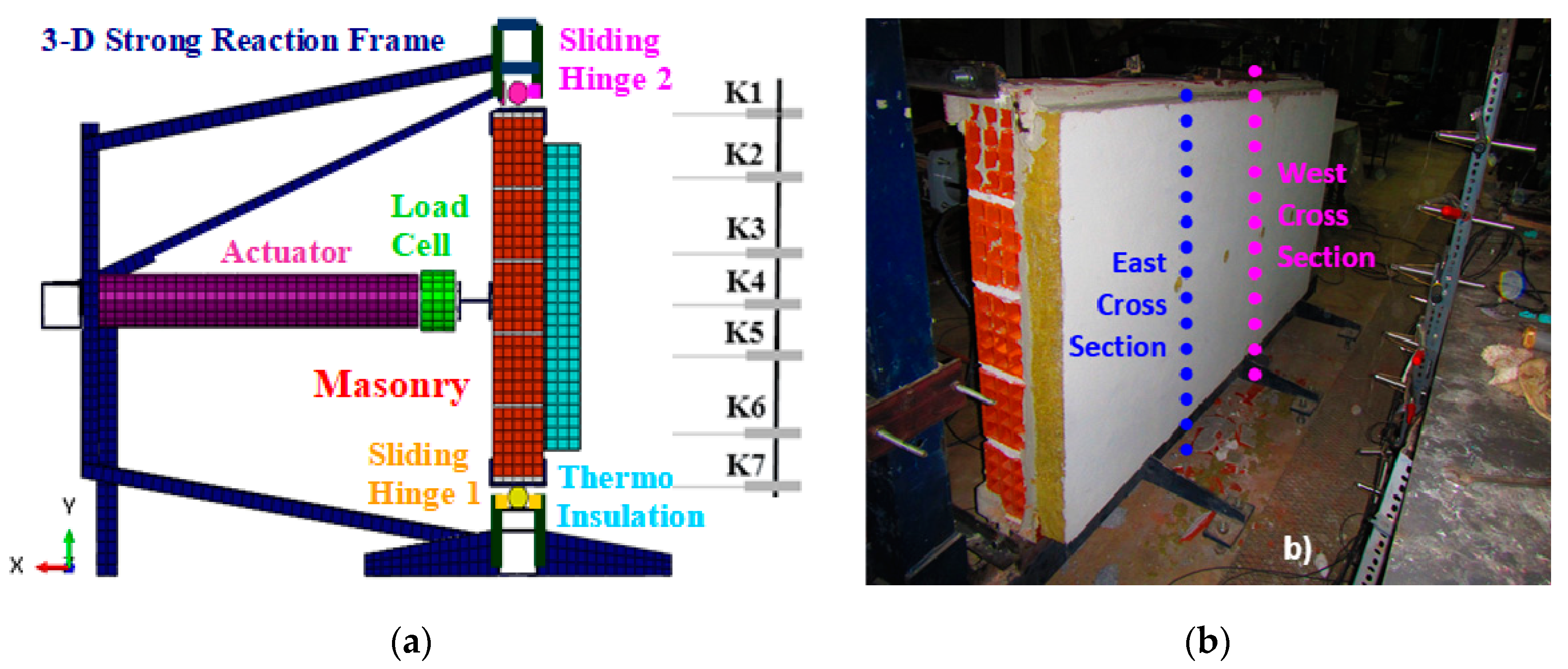
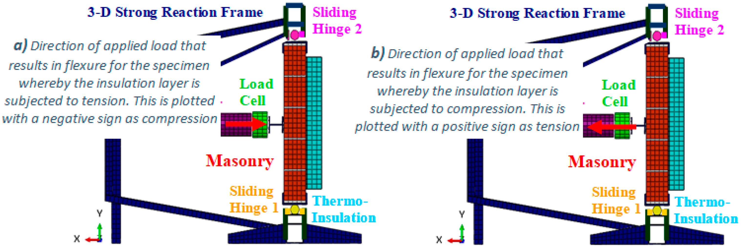
2.1. Test Set-Up and Instrumentation

The behavior of each specimen was measured in terms of the variation of the applied horizontal load versus the resulting horizontal displacement profile of the masonry specimen. This was measured at two vertical cross-sections along the height of each wallet (East and West shown in Figure 3b-right) located at a distance equal to 300 mm from the vertical axis of symmetry of the masonry panel and 800 mm from its left and right free vertical boundaries, respectively. The exact location of the displacement transducers is indicated in Figure 3a-left as well as Figure 6a using the terms: Top steel, Top thermo, Up thermo, Mid thermo, Down thermo, Bottom thermo, Bottom steel. The instrumentation was placed in this way in order to be able to check the symmetry of the resulting out-of-plane response as well as the amplitude of the deformation of the upper and lower boundaries of the masonry panels. The applied out-of-plane load was of a low-frequency (0.02–0.04 Hz) cyclic nature and all response measurements were recorded in real-time by an automatic data logger. By studying the variation of the applied load against the resulting out-of-plane horizontal displacement response the limit-states in terms of out-of-plane load versus horizontal displacements were identified. From the comparative study of these limit-states between all tested masonry panels, the influence of the thermo-insulating attachments on such a flexural response was obtained.

2.2. Contents of the Present Study

The main construction details of the tested specimens together with the basic mechanical properties of all materials derived by laboratory measurements, conducted exclusively by the authors, are next presented in summary form (Section 3). More details are reported by Manos et al. [49]. Selected results that describe the most important aspects of the measured out-of-plane flexural performance of the masonry wallets, with or without thermo-insulation, is presented in Section 4, derived from an extensive experimental sequence conducted exclusively by the authors. The discussion of the observed performance of the tested masonry wallets is included in Section 5. In Section 6 the numerical modeling of the examined wallets together with the predicted performance is presented and discussed. Finally, the observations of the ongoing research are given in Section 7 together with the final conclusions.

3. Specimen Construction and Mechanical Properties of the Used Materials

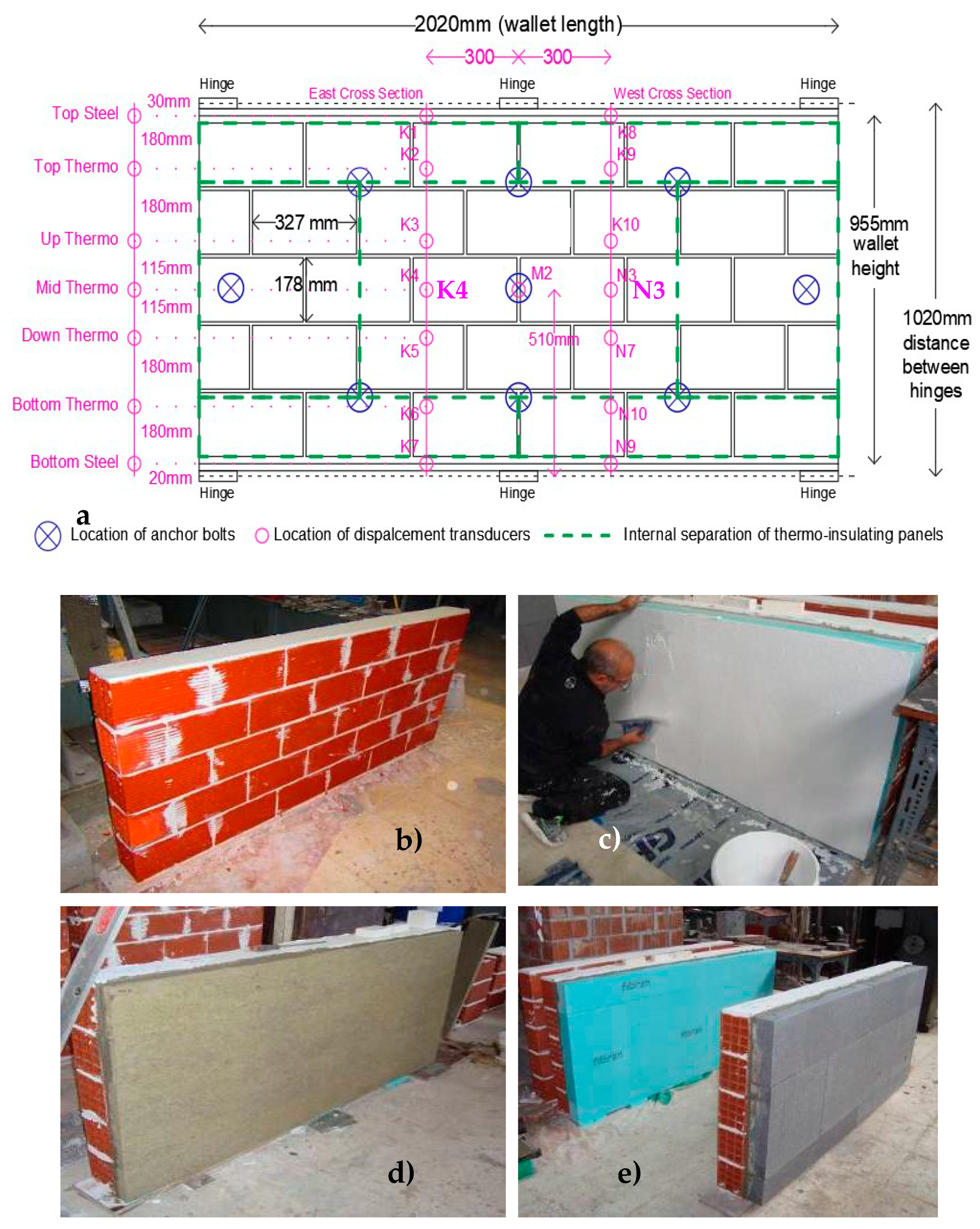
3.1. Construction of the Tested Materials

A description of the construction details can be found in [49]. Figure 7 depicts the cross-section of a thermo-insulated attachment bonded through a special adhesive mortar together with the brick masonry substrate (with dimensions 995 mm by 2020 mm and a thickness of 150 mm). Three different thermo-insulating materials were used as ETICS, namely extruded polystyrene (XPS), expanded polystyrene (EPS) and mineral wool (MW) having a thickness of either 50 or 100 mm bonded with the adhesive mortar covering about 60% of panel area for XPS and EPS panels and 100% of the MW panels. Finally, plastic anchors were also installed. The tests were performed three months after completing construction.

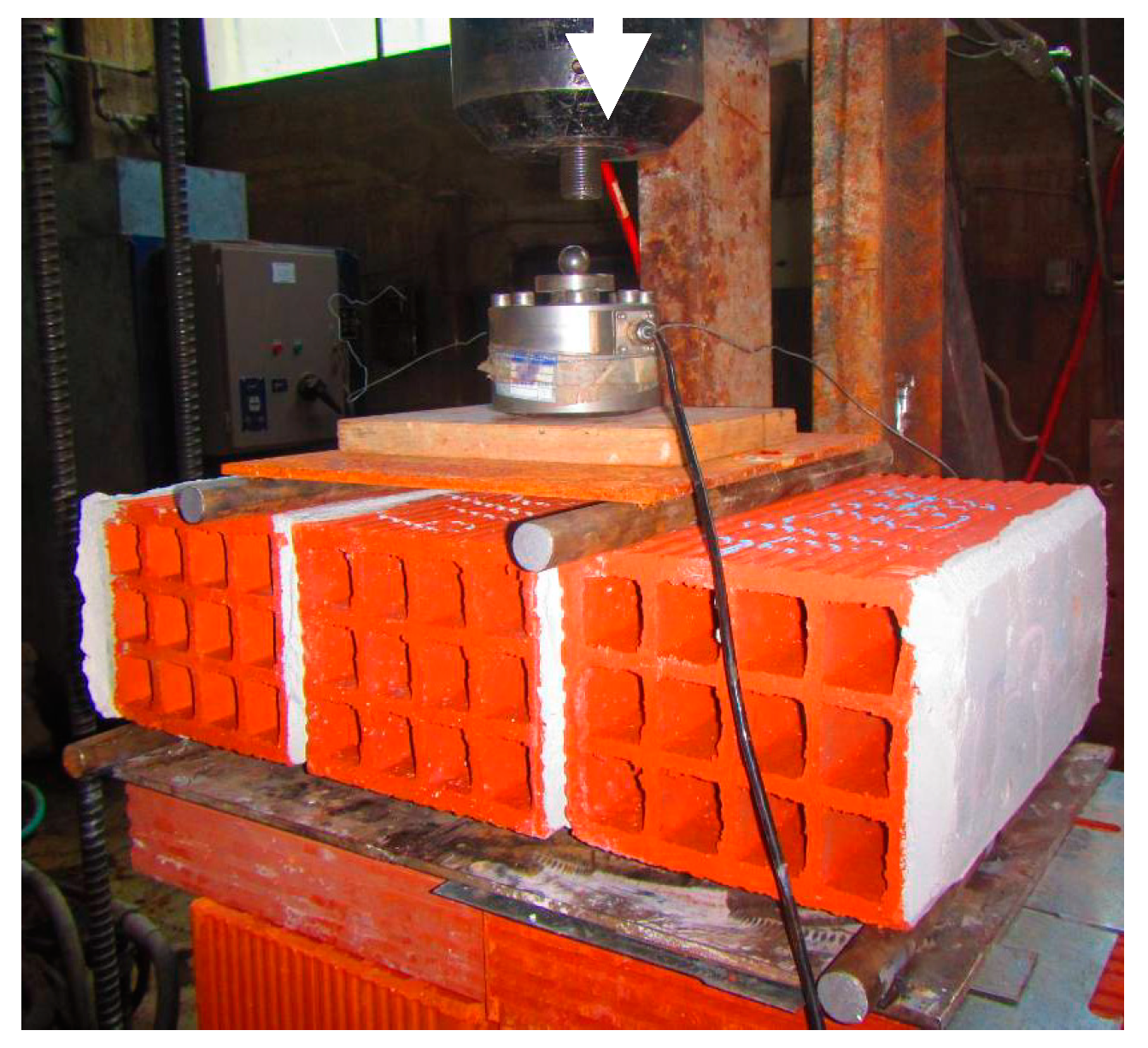
3.2. Characterization of the Materials Used in Building the Masonry and the Thermo-Insulating Facades

All specimens were built by builders following the relevant prototype work conditions. They employed, typical in Greece, hollow clay brick units with 12 horizontal holes, that had nominal dimensions: length = 330 mm, height = 180 mm and thickness = 150 mm. Information on the masonry mechanical characteristics found according to European Standards ([46,88,89,90]) is reported in [49] together with the basic mechanical properties of all the employed thermo-insulating materials ([91,92,93,94,95]). Table 1 lists only the relevant information on the compressive and flexural strength of the masonry. The values listed in columns (1) and (3) of Table 1 were found from laboratory tests performed by the authors. An overview of the bond strength properties between the used adhesive mortar and either the masonry substrate or the thermo-insulating panels is also presented by Manos et al. [49] and is not repeated here. The measured fxk1 value equal to 0.168 MPa is larger than the corresponding characteristic value provided by Euro-code 6 for mortar type M2 equal to 0.1 MPa [88].
The flexural strength normal to bed-joints was determined from simple triplet tests using a typical four-point bending loading arrangement shown in Figure 8. The monotonic applied load was measured in real time. These triplet specimens were built and tested at the same time and with the same materials that the masonry wallets were built. The two mortar joints of these triplets were subjected to flexure leading to the fxk1 average value listed in column 3 of Table 1.
The fxk1 value listed in column 3 of Table 1 was obtained through the average maximum load measured during these tests, which were conducted at the time when the wallet out-of-plane test sequence reported in Section 4 commenced.
Pull-off tests were conducted, according to the relevant EN standard [95], in order to define the bond strength between the masonry and the mortar, which was used to attach the ETICS and either the masonry substrate or the thermal insulating panels in a direction perpendicular to the wall’s plane. Details on these tests are described by Manos et al. [49]. The corresponding values are also listed in Table 2. As it was proved the bond strength between the adhesive mortar and all thermo-insulating materials was substantially smaller than the bond strength between the adhesive mortar and the masonry. This indicates that the dominant mode of failure would be the detachment of the thermo-insulating material from the adhesive mortar rather than the mortar–masonry interface. The direct tensile strength of all thermal insulating materials was measured. In the case of the XPS specimens this strength is larger than the corresponding bond strength. Thus, the failure surface during the pull-off tests was the contact interface between the XPS and the adhesive mortar. On the contrary, EPS and MW specimens’ failure surface was within the volume of the insulating material at a small distance from the contact interface [49].

4. Out-of-Plane Tests of the Masonry Wallets—Measurements

This study included numerous specimens without or with thermo-insulation attachments. Results of the measured out-of-plane performance, obtained from the following selected seven typical specimens listed in Table 3, are presented and discussed here. One of these specimens represents the control specimen without any thermo-insulating attachment; two of them have extruded polystyrene (XPS), three of them have expanded polystyrene (EPS) and one of them is with mineral wool (MW). The thickness of these thermo-insulating attachments is also listed in this table, being either 50 or 100 mm. In what follows, results from these specimens with 100 mm thickness will be presented and discussed in some detail. Moreover, the observed performance of all seven specimens will be also presented and discussed in tubular form.

4.1. Out-of-Plane Load-Displacement Response of Masonry Wallet without or with Thermo-Insulating Attachment

In what follows, the observed flexural behavior of four wallets will be presented in terms of plots portraying the variation of the applied out-of-plane horizontal load versus the resulting horizontal out-of-plane displacement at mid-height (Point K4-West, Figure 6a). It was selected to commence the forcing sequence for each wallet towards the direction designated as “compressive load” (Figure 5a left) in order to be able to reach first the limit flexural load in this direction. The cyclic load was applied with a relatively slow variation in time (0.02–0.04 Hz) with a gradual increase in amplitude aiming to determine the peak value (minimum load) in the direction that the thermo-insulation is subjected to tension (Figure 5a left). Therefore, it is only a crude approximation of a seismic type loading. From preliminary testing it was ascertained that the peak load in this direction had absolute value larger than the corresponding peak load value in the opposite direction (maximum load, designated as tension (Figure 5b right)). This was confirmed by the measured behavior of all tested wallets. In what follows, the obtained flexural performance of four masonry wallets, in terms the variation of the applied out-of-plane horizontal load versus the resulting horizontal out-of-plane displacement at mid-height during the loading cycles led to the peak load. One of these masonry wallets is without any thermal insulation representing the control specimen. All the remaining three wallets have thermo-insulating attachments with a thickness of 100 mm; the first thermo-insulation is made of mineral wool (MW), the second is made of expanded polysterene (EPS) and the third is made of extruded polysterene (XPS). The following summarize the main observations of the measured response included in Figure 9a–d. Further comparison of the measured behavior is also included in Section 4.2, Section 4.3, Section 4.4 and Section 4.5. as well as in Section 5 (Table 4).
-
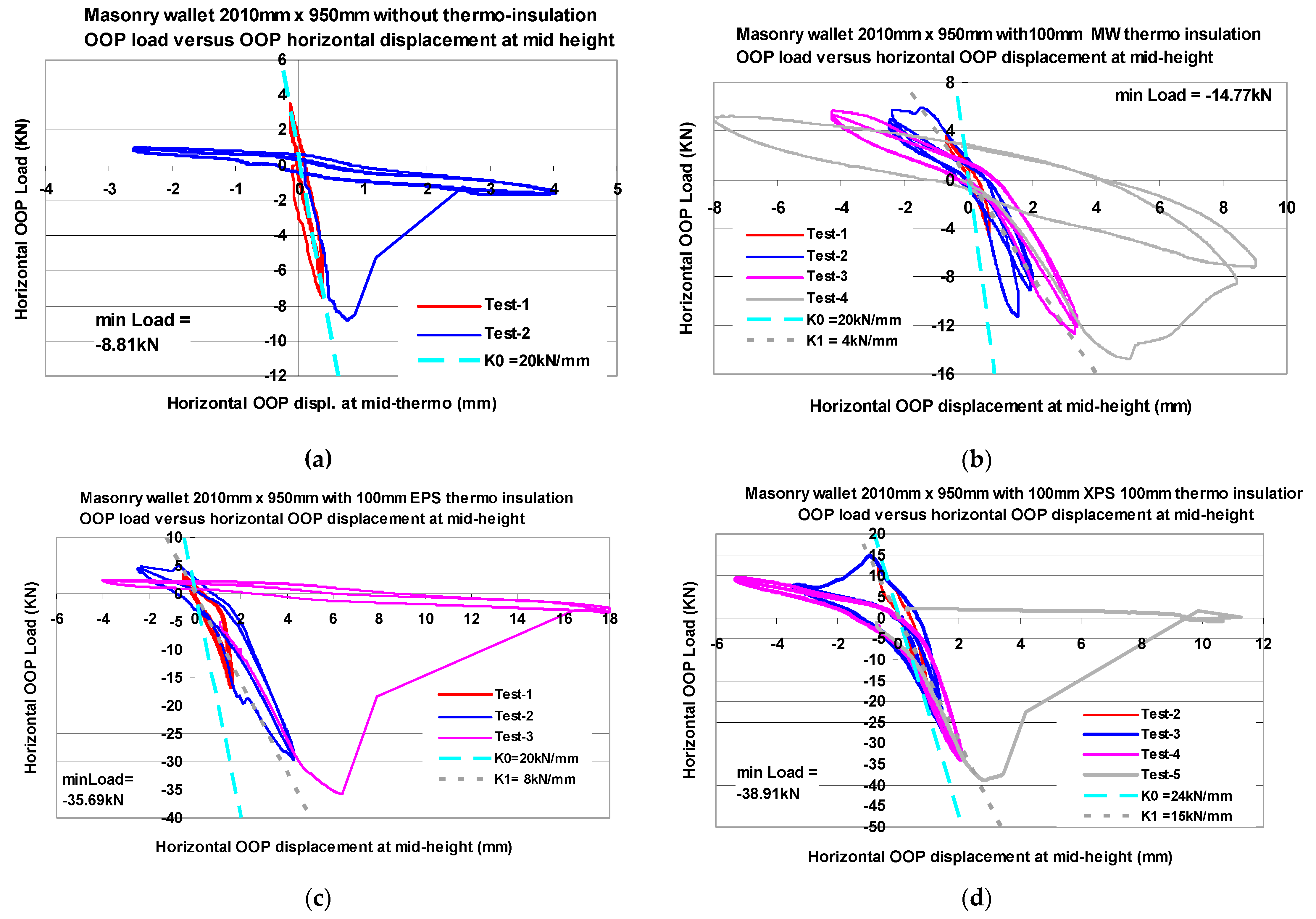
Initially, the first cycles of small load-displacement amplitudes are demonstrating an almost linear response with an initial stiffness K0 = 20–24 kN/mm.
-
The gradual increase in the applied load-displacement amplitude is accompanied by a decrease in the obtained stiffness. For the masonry wallet without thermo-insuation the peak load, as expected, is reached within four loading cycles with a relatively small increase in the displacement amplitude and is accompanied with a sudden decrease of the bearing capacity and a large deformability (brittle behavior).
-
In contrast, all three specimens with thermo-insulation required a significant increase in the load and displacement amplitudes in order to reach the peak load beyond which a similar brittle behavior follows (4–8 loading cycles, Table 4). Until this peak “compressive” load is reached the subsequent loading cycles demonstrate a decreased stiffness (K1 = 15–5 kN/mm), compared to the K0 initial stiffness, together with load-displacement cycles with energy dissipation characteristics. The same can be observed but to a lesser degree when the load direction is reversed (“tensile” load). This must be attributed to the interaction of the thermo-insulation with the crack formation of the masonry substrate as well as the partial debonding. The ratio of the mid-height displacement for peak load over the corresponding “assumed yield” displacement increased from approximately 1.4 for the masonry wallet without thermo-insulation to approximately 2.0 for the wallets with XPS thermo-insulation and to approximately 3.0 for the wallets with either EPS or MW thermo-insulation (Table 4).
-
The peak load increase in absolute value terms is larger for the XPS and EPS thermo-insulation attachments than that observed for the mineral wool (MW) attachment. The opposite can be observed for the relative amplitude of plastic deformations before reaching the peak load; these are somewhat larger for the MW and EPS than for the XPS thermo-insulating attachments.

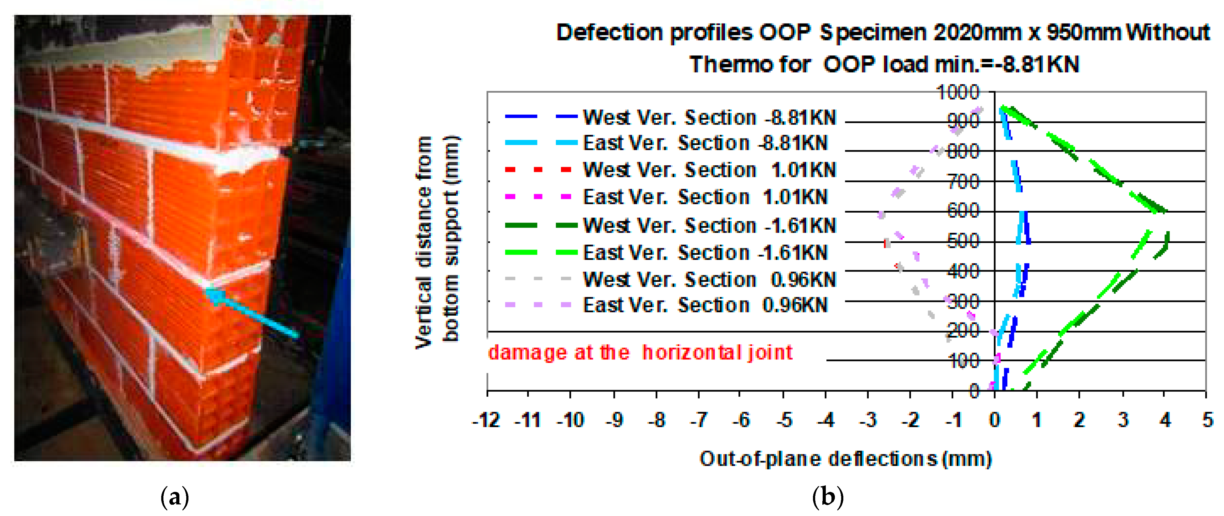
4.2. Masonry Wallet without Any Thermo-Insulating Attachment (Code Name WOP0A)

The obtained out-of-plane displacement profiles of the vertical cross-sections (East and West) of this specimen are plotted in Figure 10 for four distinct time steps of the loading sequence. First, it is for the time step when the out-of-plane load obtains its minimum value (−8.81 kN, peak compression) for a maximum out-of-plane displacement at mid-height approximately equal to 1 mm. This load resulted in the partial formation of a horizontal crack at the bed-joints located at mid-height of the masonry wallet. Reversing the direction of the load the wall could displace approximately 2.5 mm for a tensile load equal to 1.01 kN. During the next load reversals, the out-of-plane deformations increased accompanied with a significant decrease of the applied out-of-plane load (in absolute value) together with the spread of cracking for the mortar bed-joints located at mid-height of this masonry wallet (Figure 10). The plotted East and West displacement profiles in Figure 10b-right are almost identical for every time step, thus demonstrating the uniform deformation behavior of the tested specimen along its length. The out-of-plane displacement amplitude at the top and bottom horizontal boundaries is quite small when compared to the out-of-plane displacement values attained at mid-height.

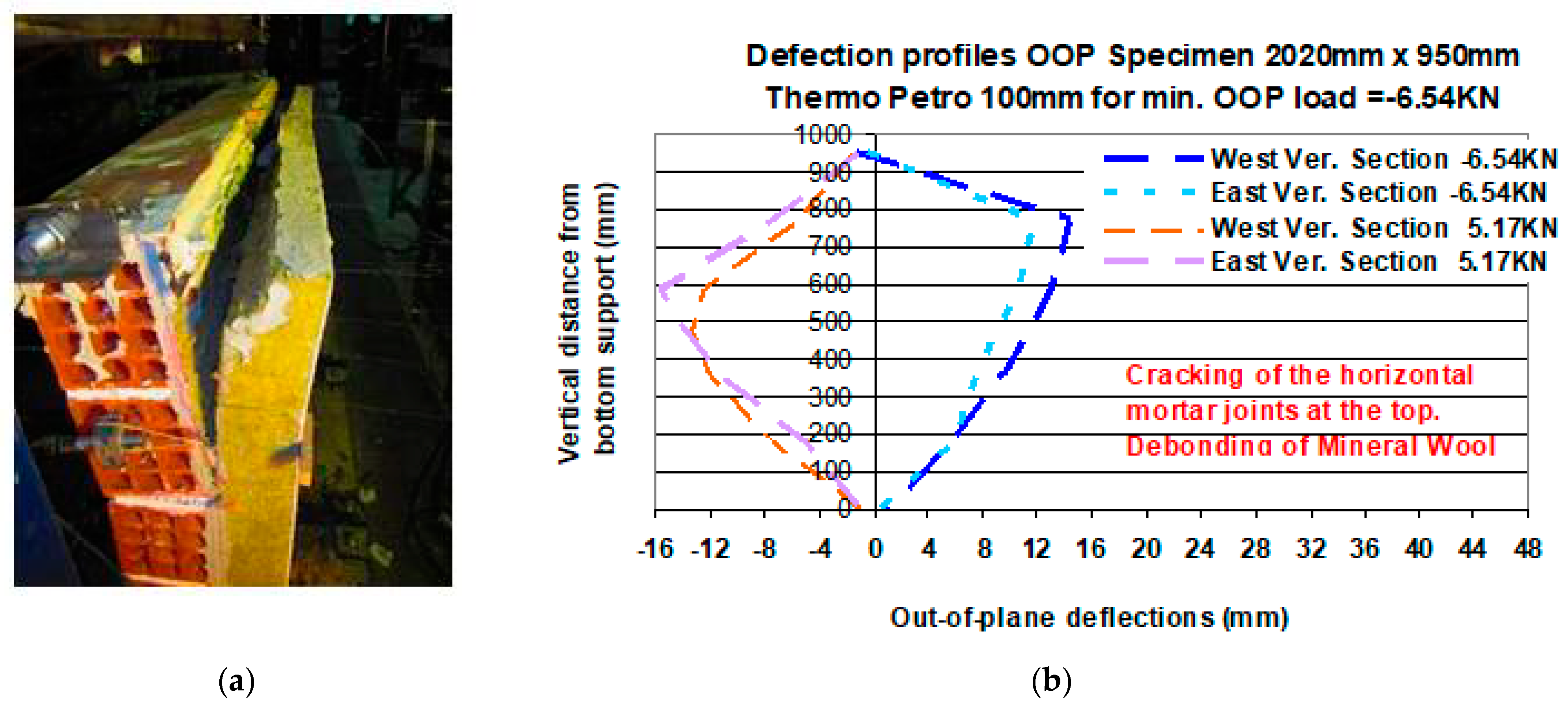
4.3. Masonry Wallet with a Mineral Wool (MW) Facade of 100 mm Thickness Subjected to Out-of-Plane Flexure (WOPM100A)

This is a masonry wallet with a mineral wool (MW-Petro) thermo-insulating attachment having a thickness of 100mm in one of its facades. The obtained out-of-plane displacement profiles of the East and West vertical cross-section of this specimen are plotted in Figure 11b-right for two (2) distinct time steps of the loading sequence. For one of these time steps the out-of-plane load obtains its minimum value (−14.77 kN, peak compression) for an out-of-plane displacement at mid-height approximately equal to 6 mm. This represents the load that resulted in the partial formation of horizontal cracks at the bed-joints located near the top of the masonry wallet accompanied by the initiation of the debonding of the mineral wool from the masonry facade (Figure 11a-left). Reversing the direction of the load the wall could displace approximately 8 mm for a tensile load equal to 5.21 kN. At the next load reversals (Figure 12b-right) the out-of-plane deformations would increase (14 mm) for a significant decrease (in absolute values) of the applied out-of-plane load (−6.54 kN) being accompanied with the spread of mortar cracking at the horizontal bed-joints together with large spread of the debonding between the mineral wool thermo-insulating attachment and the masonry facade (Figure 12a-left). Again, the plotted East and West displacement profiles remain almost identical during each loading time step, which ensures the uniform deformation pattern of the tested specimen along its length. Moreover, the out-of-plane displacement amplitude at the top and bottom horizontal boundaries is quite small when compared to the maximum out-of-plane displacement value attained at mid-height.

4.4. Masonry Wallet with an Expanded Polystyrene (EPS) Facade of 100 mm Thickness Subjected to Out-of-Plane Flexure (WOPE100A)

This is a masonry wallet having in one of its facades an expanded polyester (EPS) thermo-insulating attachment with a thickness of 100 mm. The obtained out-of-plane displacement profiles of the East and West vertical cross-section of this specimen are plotted in Figure 13b-right for two (2) distinct time steps of the loading sequence. The first time step is for the loading stage when the out-of-plane load obtains its minimum value (−29.57 kN, peak compression) for an out-of-plane displacement at mid-height approximately equal to 5 mm. This load did not result in any damage. Reversing the direction of the load the wall could displace approximately 3 mm for a tensile load equal to 4.96 kN. At the next load reversals (Figure 14b-right) the out-of-plane deformations would increase (6 mm) for an out-of-plane load equal to −35.62 kN (compression). For the subsequent load reversals, a significant decrease of the applied out-of-plane load (in absolute values) could be observed (+2.45 kN/−3.18 kN) being accompanied with extensive debonding between the expanded polyester thermo-insulating attachment and the masonry facade of the upper part of the masonry wallet (Figure 14a-left). This is also depicted by the out-of-plane displacement profiles plotted in Figure 14b-right corresponding to these decreased load levels (+2.45 kN/−3.18 kN). Again, the plotted East and West displacement profiles remain reasonably identical, which shows that the deformation pattern of the tested specimen along its length remained approximately uniform. Moreover, the out-of-plane displacement amplitude at the top and bottom horizontal boundaries remains reasonably small when compared to the maximum attained out-of-plane displacement value at mid-height, despite the relatively high amplitude of the applied load.

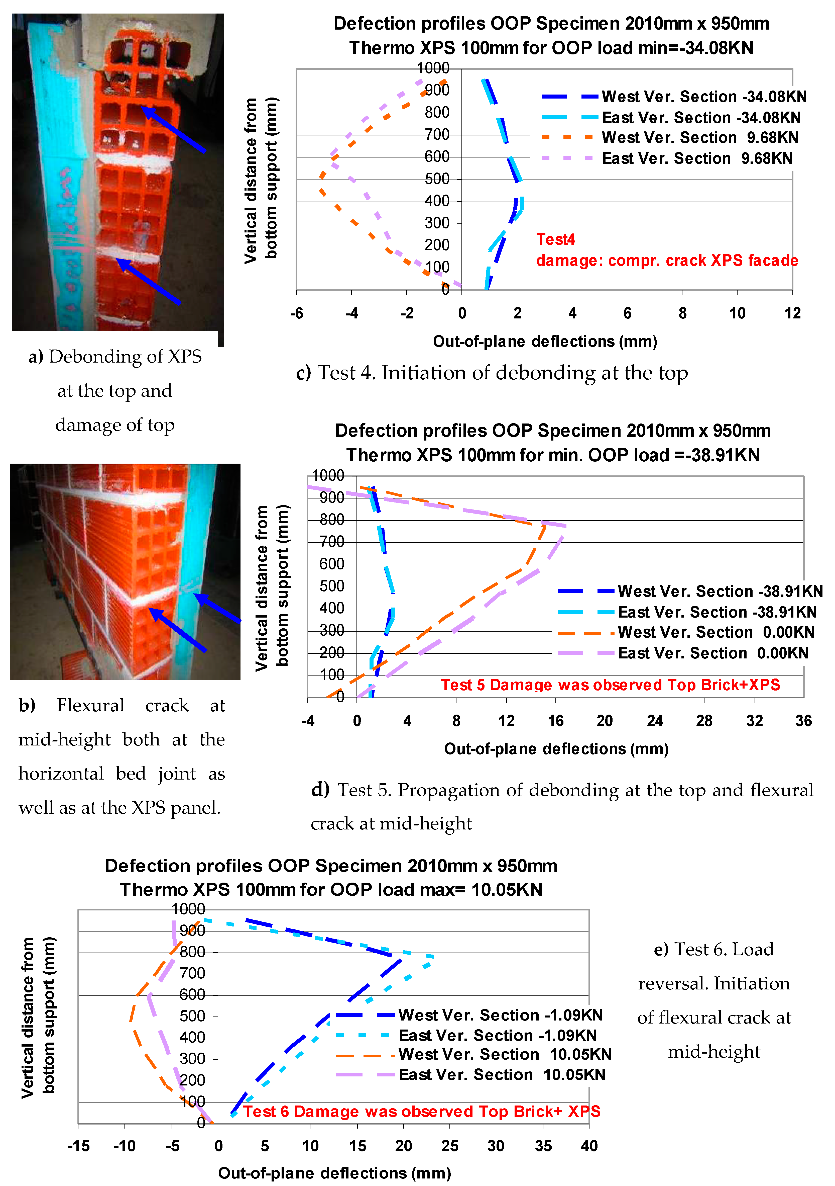
4.5. Masonry Wallet with an Extruded Polystyrene (XPS) Facade of 100 mm Thickness Subjected to Out-of-Plane Flexure (WOPX100B)

The obtained out-of-plane displacement profiles of the East and West vertical cross-sections of this specimen, having in one of its facades an extruded polyester (XPS) thermo-insulating attachment with a thickness of 100 mm, are plotted in Figure 15c–e-right. The observed damage is depicted in Figure 15a,b-left.
During test 4 (Figure 15c-right), the initiation of the debonding between the XPS panel and the masonry facade at the top was observed for a compressive load −34.08 kN and an amplitude of the out-of-plane displacement at mid-height approximately equal to 2.5 mm. The subsequent load reversal resulted in a tensile load equal to 9.68 kN for an out-of-plane displacement at mid-height approximately equal to −5 mm. For the next test (No. 5, Figure 15d-right), the compressive load attained its minimum value equal to −38.91 kN for an out-of-plane displacement at mid-height approximately equal to 3.5 mm. A following large increase of the out-of-plane displacement amplitude (20 mm) resulted in a significant propagation of the debonding between the XPS panel and the masonry facade at the top together with a large drop, eventually, of the out-of-plane bearing capacity. Figure 15e-right depicts the observed performance during the next test (No. 6). The amplitude of the tensile load is equal to 10.05 kN for an out-of-plane displacement at mid-height approximately equal to −7 mm. The horizontal crack through the mortar bed-joint at mid-height propagated to the XPS at this location (Figure 15a,b left).

5. Observed Performance

5.1. Observed Out-of-Plane Performance of the Tested Wallets

Table 4 lists the summary results of this out-of-plane flexural behavior campaign in terms of minimum compressive (row 3)/maximum tensile (row 4) measured load together with the corresponding out-of-plane horizontal displacement measured at the mid-height of the wallet. Row 1 and row 2 list a brief description of the tested specimens whereas row 5 includes the increase (%) in the flexural capacity as expressed by the peak (minimum) “compressive” load value measured for each specimen compared to the corresponding value of the control specimen without any thermo-insulation (“bare”). This is repeated in row 6 for the peak (maximum) “tensile” load values when this was measured during testing before the development of any damage. In these cases, the maximum tensile load for the “bare” specimen was assumed to have the same absolute value with the minimum “bare” specimen measured compressive load value. Row 7 lists the number of loading cycles used towards reaching the peak (minimum) “compressive” load and the loading cycles after this point. Row 8 lists the initial measured stiffness value (K0) together with the stiffness value when the peak “compressive” load was reached. Row 9 lists the values of the ratio of the horizontal out-of-plane displacement at peak “compressive” load with the corresponding value that can be assumed as “yield” displacement in the load versus displacement cyclic sequence. Finally, row 10 lists the observed damage together with the maximum value of the measured out-of-plane horizontal displacements at mid-height for each wallet at the final stage of the loading sequence. It becomes evident that in all cases one of the prevailing forms of damage is the debonding either at the adhesive mortar–thermo-insulation interface (for XPS) or within the volume of the thermo-insulating material near this interface (for EPS and MW), as was already underlined by Manos et al. according to the performed material tests [49].

5.2. Discussion of the Measured Behavior

-
The wallets having a thermo-insulating attachment showed an increase of the measured out-of-plane flexural capacity. When the thermo-insulating panels are subjected to tension form flexure and their thickness is 100 mm, this increase is 68%, 304%, 342% for the MW, the EPS and the XPS, respectively. A somewhat similar increase is also evident for the case with thermo-insulating panels having thickness equal to 50 mm.
-
A part of this increase is due to the adhesive mortar layer that is common to all the thermo-insulating attachments. Another part is due to the contribution of the various thermo-insulating materials. This contribution varies according to the corresponding variation of the tensile strength of the thermo-insulating materials in flexure.
-
A limiting factor in capitalizing on the flexural tensile strength of the insulating material is the relatively low bond strength between the adhesive mortar and these materials either in the tangential or in the normal direction of the bond surface (Table 3). This is evident from the fact that in almost all cases the limit state was that of debonding of the insulating panels either at the top or at the bottom of the masonry panel.
-
These thermo-insulating attachments, being under flexural tension, results in values of the out-of-plane displacements for peak compressive load significantly larger (XPS 3–6 mm, MW and EPS 5 mm) than those measured for the specimen without any thermo-insulating attachment (“bare”, 2 mm).
-
When the applied load was reversed, thus subjecting the thermo-insulating attachments in flexural compression, the increase of the out-of-plane flexural capacity was considerably smaller than the corresponding increase when the same insulating panels were under flexural tension. Contributing factors for this is the low compressive strength of these materials relatively to the corresponding tensile strength.
-
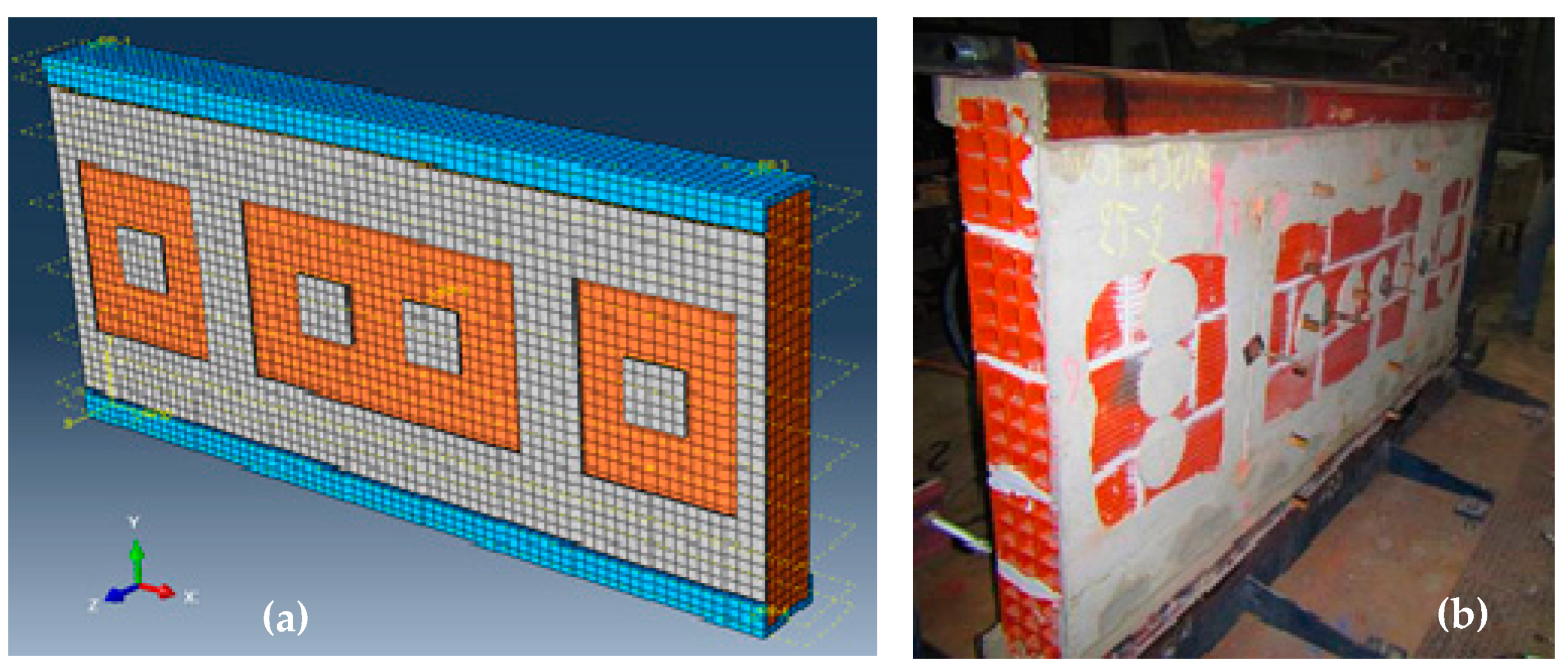
In all tested wallets, the presence of the thermo-insulating material did not alter the initial dominant flexural failure mode which, as expected, was the formation of horizontal cracks at the bed-joints near mid-height. This flexural response mechanism was accompanied in subsequent load cycles by the debonding of the insulating panels from the masonry substrate at the top and bottom horizontal boundaries of the tested specimens. In all cases, this debonding occurred for relatively large values (approximately more than 5 mm) for the out-of-plane displacements at mid-height of each wallet. For such large out-of-plane deformations the corresponding flexural capacity was significantly reduced.
-
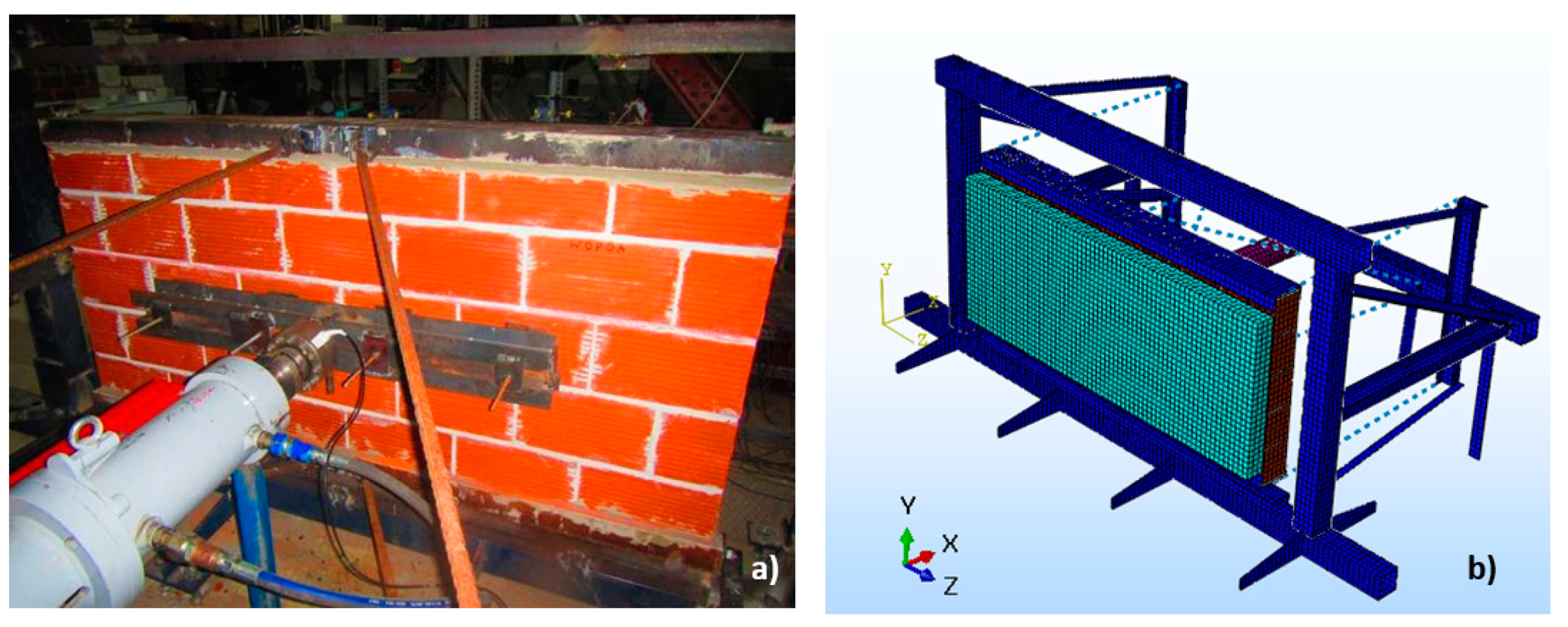
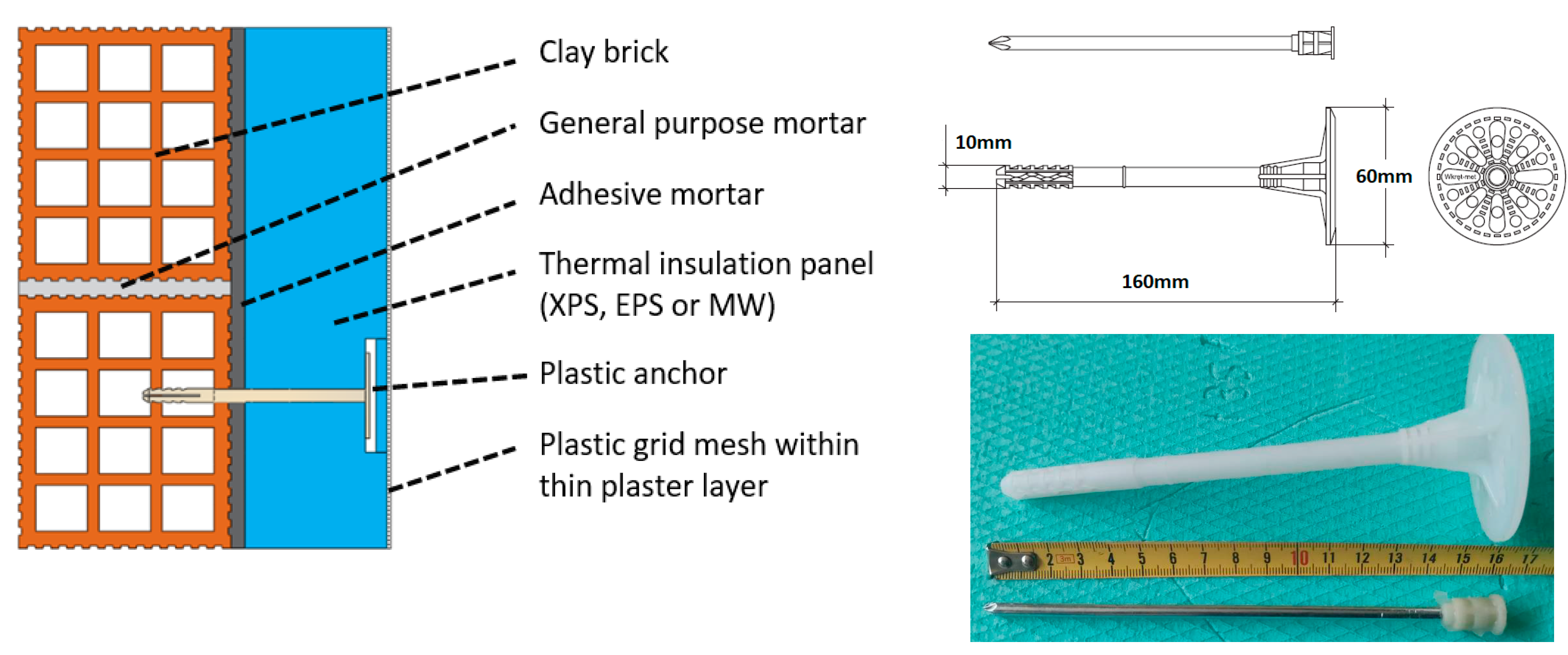
Apart from the observed cracking and the subsequent debonding of the thermo-insulating attachments for such large out-of-plane displacements (in excess of 15 mm at mid-height of the wallet at the final loading stages) there was no incident of an insulating panel-unit detaching completely from the facade of the masonry wallet. This must be attributed to the protective action of the plastic anchors placed in key location for this purpose (Figure 13a-left).
-
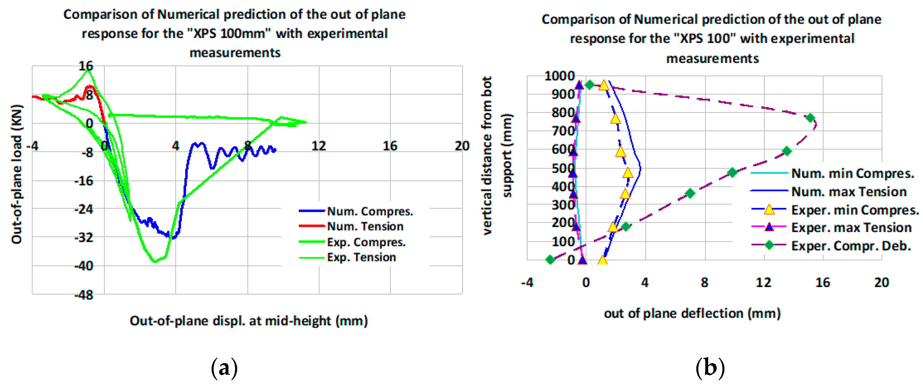
The increase in the out-of-plane flexural capacity was larger for the EPS facades 100 mm thick than for those being 50 mm thick. However, for the XPS facades, the flexural capacity for a thermo-insulating facade 50 mm thick is larger than that for a facade 100 mm thick. This must be attributed to the fact that, due to a local weakness of the clay bricks in these XPS wallets, the local breaking of the masonry near the horizontal support developed apart from the cracking of the horizontal mortar joints and the debonding of the thermo-insulating facades from the masonry. As can be seen, the wallets with XPS facades resisted much higher out-of-plane loads than the corresponding EPS or MW wallets. This is partly due to the higher bond strength developed between the adhesive mortar the XPS panel combined with the higher flexural tensile strength of the XPS material itself than those for the EPS or MW (Table 3). The resulting higher value of the applied out-of-plane load resulted in certain cases to the breaking of the clay bricks, due to local weakness in the brick units.
-
Until this peak “compressive” load is reached the subsequent loading cycles demonstrate a decreased stiffness (K1 = 15–5 kN/mm), compared to the K0 initial stiffness (K0 = 24–20 kN/m), together with load-displacement cycles with energy dissipation characteristics. The same can be observed but to a lesser degree when the load direction is reversed (“tensile” load). This must be attributed to the interaction of the thermo-insulation with the crack formation of the masonry substrate as well as the partial debonding. The value of the ratio of the mid-height displacement for peak load over the corresponding “assumed yield” displacement increases from approximately 1.4 for the masonry wallet without thermo-insulation to approximately 2.0 for the wallets with XPS thermo-insulation and to approximately 3.0 for the wallets with either EPS or MW thermo-insulation.

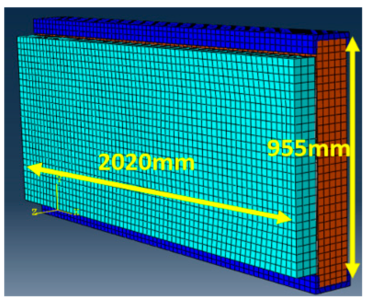
6. Numerical Simulation of the Out-of-Plane Flexure for the Tested Wallets

Different numerical methodologies are reported in the literature towards simulating the non-linear behavior of masonry walls. Asteris et al. reviewed the most popular numerical approaches for numerically simulating the masonry infill behavior [96,97]. Manos et al. [49] included an overview of the validations of numerical simulations of the non-linear behavior of masonry walls “bare” or with different retrofitting schemes ([30,31,32,41,42,43,44,45,59,60,98,99,100]). More complex modeling strategies are employed when attempting to numerically simulate the behavior of masonry retrofitted in various ways. These strategies utilize either shell elements or solid finite elements and can be classified either as macro-models or as micro-models. Macro-models are adopted by many researchers in order to reduce the computational cost [32,98]. Noor-E-Khuda et al. [99] investigated the effectiveness of various retrofitting schemes for unreinforced masonry walls using layered shell elements. The numerical results are in good agreement with the experimental measurements. Bi-dimensional models were also examined by Gattesco et al. [81] and Galvez et al. [100]. In both cases, they used experimental measurements to calibrate the numerical simulations thus achieving good agreement. Bello et al. [39] developed numerical models based on the smeared cracking theory towards deriving homogenized material properties for both the masonry as well as the FRCM composite. The strengthened models predicted well the observed great increase of bearing capacity by the applied retrofitting. A Drucker–Prager non-linear constitutive law was adopted by Khan et al. [86] for the numerical representation of 3D macro-models of masonry walls together with 2D shell elements representing geo-synthetic coatings. It was found that the addition of such coatings increased the maximum out-of-plane applied load more than 50%. The numerical results discussed here were obtained employing a macro-modeling strategy for the masonry walls employing test results in order to quantify the relevant properties of homogenized masonry, utilizing the capabilities of commercial software [101]. The same numerical methodology was used before in an effort to investigate the in-plane behavior [49].

6.1. Comparison between Numerical Predictions and Observed Behavior in the Current Study

The masonry substrate was formed with 3-D finite elements adopting a homogenized material obeying the concrete damaged plasticity (CDP) constitutive law for masonry (Table 5) ([102,103]). Initially, the numerical model for the control “bare” specimen was formed, shown in Figure 16, and the relevant predictions of its flexural response were compared with the observed behavior, found to be satisfactory (Section 6.1.1). All the parameters introduced for the homogenized masonry are listed in Table 5.
The post-failure tensile behavior can be determined either by the tension stiffening incorporated in a post-failure stress–strain relation or by applying a fracture energy cracking criterion [101]. The tension stiffening approach was employed here towards simulating numerically the observed behavior of the wallets tested at the laboratory without or with thermo-insulation attachments in the framework of the present study (Section 6.1.1, Section 6.1.2, Section 6.1.3 and Section 6.1.4). Towards examining these two post-failure capabilities, the observed behavior of the masonry wallet without any thermo-insulation was numerically simulated employing either the tension-stiffening or the fracture energy numerical approach. They both yielded almost identical predictions with the equivalent tensile fracture energy for the masonry wallet of this study equal to 18 Nmm/mm2. This value of the fracture energy is in good agreement with similar studies reported in the literature. Lourenco et al. [98] developed a plasticity model for clay masonry walls which features a Rankine-type criterion for tension and the tensile fracture energy was defined equal to 20 Nmm/mm2, calibrated by experimental results. The adhesive mortar joint between the masonry and the thermo-insulating panel-units is numerically simulated with 3-D solid finite elements (Figure 18a-left), having 10 mm thickness and a concrete damage plasticity constitutive law (Table 6) defined again by utilizing relevant test results of this study. For the parameters required to define the plasticity properties of masonry and adhesive mortar material law the default values included in the employed commercial software [101] were adopted, while the value of the dilation angle was set equal to 30°. The thermo-insulating panels were also numerically simulated with 3-D solid finite elements having elastic behavior according to relevant measurements. The interface between the masonry substrate and the adhesive mortar assumes perfect bond, according to the observed behavior whereas the interface between the adhesive mortar and the thermo-insulating attachment was provided instead with non-linear behavior, according to test results (Table 2) obtained by measurements conducted exclusively by the authors [49]. This was done in order to simulate the debonding between the adhesive mortar and the thermo-insulating attachment, which was shown to be critical in the observed behavior. This later interface uses nodal interaction with cohesive–friction behavior determined according to tests for both the normal and the tangential behavior. Figure 17 depicts a cross-section of the tested specimens with all the details of the above numerical simulation.

6.1.1. Numerical Simulation of the Out-of-Plane Behavior of the Masonry Wallet without any Thermo-Insulating Attachment (“Bare”)

Initially, the out-of-plane behavior of the masonry wallet without any thermo-insulating attachment (“bare”) was numerically simulated, following the previously described steps (Figure 18b-right). Figure 19 depicts the numerical out-of-plane response in terms of applied horizontal load versus corresponding horizontal displacement at mid-height of this specimen. It must be clarified that this response was obtained by applying the out-of-plane load separately either as compressive force (negative load versus positive out-of-plane displacement) or as tensile force (positive load versus negative out-of-plane displacement). No attempt was made to numerically simulate the cyclic nature of observed response and the influence of the development and accumulation of plastic strains under reverse loading conditions.
Figure 19a-left depicts the numerically obtained out-of-plane displacement at mid-height versus the applied horizontal load, as explained before. In the same figure the corresponding measured response is also plotted. As can be seen, good agreement is reached between the numerically predicted (−8.88 kN) and the observed (−8.81 kN) minimum compressive load. The numerically predicted displacement response for the compressive load is also in agreement with the measured values. Therefore, the numerical response portrays quite accurately the observed degradation of the bearing flexural capacity that is characterized by a considerable increase of the out-of-plane displacements with a significant decrease (in terms of absolute values) of the corresponding out-of-plane compressive load. In these figures, the numerically predicted response for the tensile load does not agree with the measurements. This is due to the fact that no attempt was made to numerically simulate the cyclic nature of the observed response and the influence of the development and accumulation of plastic strains under cyclic load reversals. The plotted numerical simulation of the “bare” masonry behavior for out-of-plane tensile force (Figure 19a-left) is anti-symmetrical to the one plotted for the compressive force. However, the corresponding measured plotted load versus displacement response for tensile force was recorded at the stage that this wallet had already failed during the preceding compressive load cycle. This is the underlining reason for the obvious discrepancy between observed and numerically predicted response. Despite this drawback, the following numerical simulations are based on the same approximation not attempting at present to simulate the effect of the load reversals. Therefore, the following numerical simulations that include the masonry facade were done separately for either compressive force or tensile force and not for continuous cyclic load reversals. This should be kept in mind when one compares the numerical predictions with the corresponding measurements.
As can be seen from Figure 20, the employed numerical simulation was successful in predicting the mode of failure and the flexural capacity of the masonry wallet without any thermo-insulating attachment (“bare”). In the following, this basic satisfactory numerical simulation of the masonry substrate was extended to include the thermo-insulating attachments and the adhesive mortar layer, following the construction details shown in Figure 17 and Figure 18, as described before. In the subsequent sections summary numerical results are presented for the wallets having 100 mm thick thermo-insulating attachments made of either mineral wool (MW), or expanded polystyrene (EPS) or extruded polystyrene (XPS). All these cases were studied experimentally, and the relevant results are included in this manuscript. It is again underlined that, whereas the loading sequence during testing included cyclic load reversals, the numerical results were obtained from applying the load either as a compressive force (subjecting the thermo-insulating attachments to tension) or as a tensile force (subjecting the thermo-insulating attachments to compression), without accounting for any accumulation of plastic strains from cyclic load reversals.

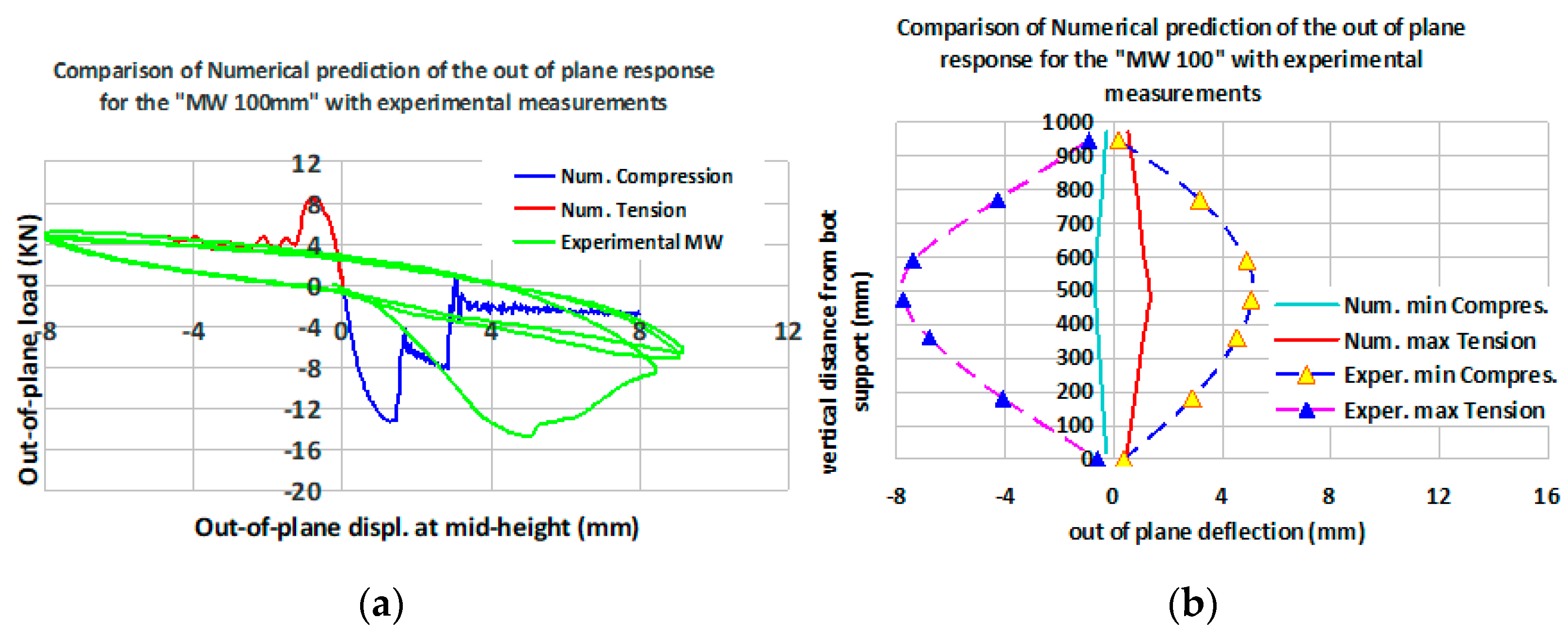
6.1.2. Numerical Simulation of the Out-of-Plane Behavior of the Masonry Wallet with Thermo-Insulating Attachment Made of Mineral Wool (“MW” with a Thickness of 100 mm)

Figure 21 depicts the numerical out-of-plane response in terms of applied horizontal load versus corresponding horizontal displacement at mid-height of this specimen which has a 100 mm thick thermo-insulating attachment of mineral wool. Figure 21a-left depicts the numerical out-of-plane response in terms of applied horizontal load versus corresponding horizontal displacement at mid-height of this specimen whereas Figure 21b-right shows the numerical out-of-plane displacement profiles along a vertical cross-section (for either compressive or tensile force). In the same figures, the corresponding measurements are also shown. As can be seen, reasonably good agreement is reached between the numerically predicted value (−13.35kN) and the observed (−14.77kN) minimum compressive load. The numerically predicted displacement response appears to be less flexible than the corresponding measured response (Figure 22b-right). This must be attributed to the fact that the plotted measured response was preceded by at least two loading cycles of smaller amplitudes than the ones plotted here, which may have contributed to the observed flexibility. Despite this, the numerical response portrays quite accurately the observed degradation of the bearing flexural capacity that is characterized by a considerable increase of the out-of-plane displacement, which accompanies the significant decrease (in terms of absolute values) of the corresponding out-of-plane load. In these figures, the numerically predicted response for the tensile load (8.88 kN) shows similar trends with the measured values (5.21 kN) as this tensile load is significantly smaller, in terms of absolute values, than the compressive load. As already stated, no attempt was made to numerically simulate the cyclic nature of the observed response and the influence of the development and accumulation of plastic strains under reverse loading conditions. Despite this, the contribution of the thermo-insulating attachment, when in compression, seems to be well approximated even in this limited way. Figure 22a (left) depicts the predicted accumulation of the loss of contact at the interface between the masonry and the thermo-insulation, beyond the stage where the minimum compressive load was applied. Figure 22b (right) shows the observed debonding type of damage for the same masonry wallet with 100mm thick mineral wool when during testing the applied load was significantly decreased (in terms of absolute values), as compared to the minimum compressive load.

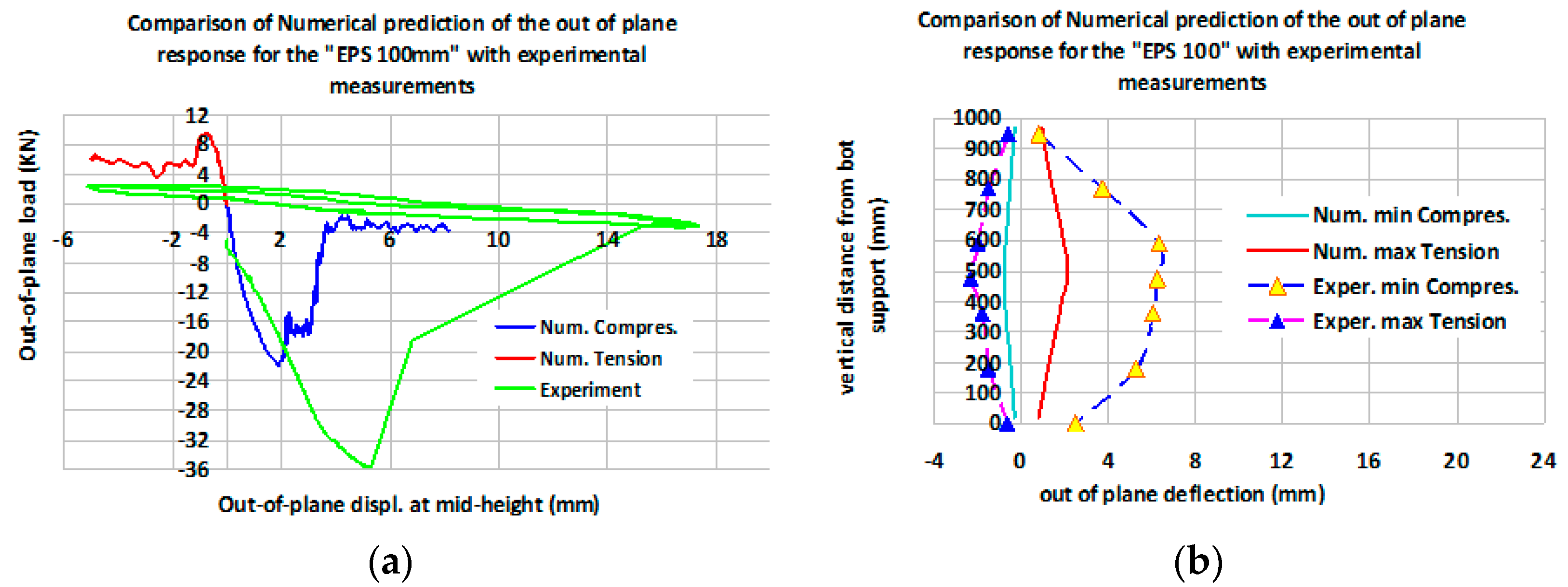
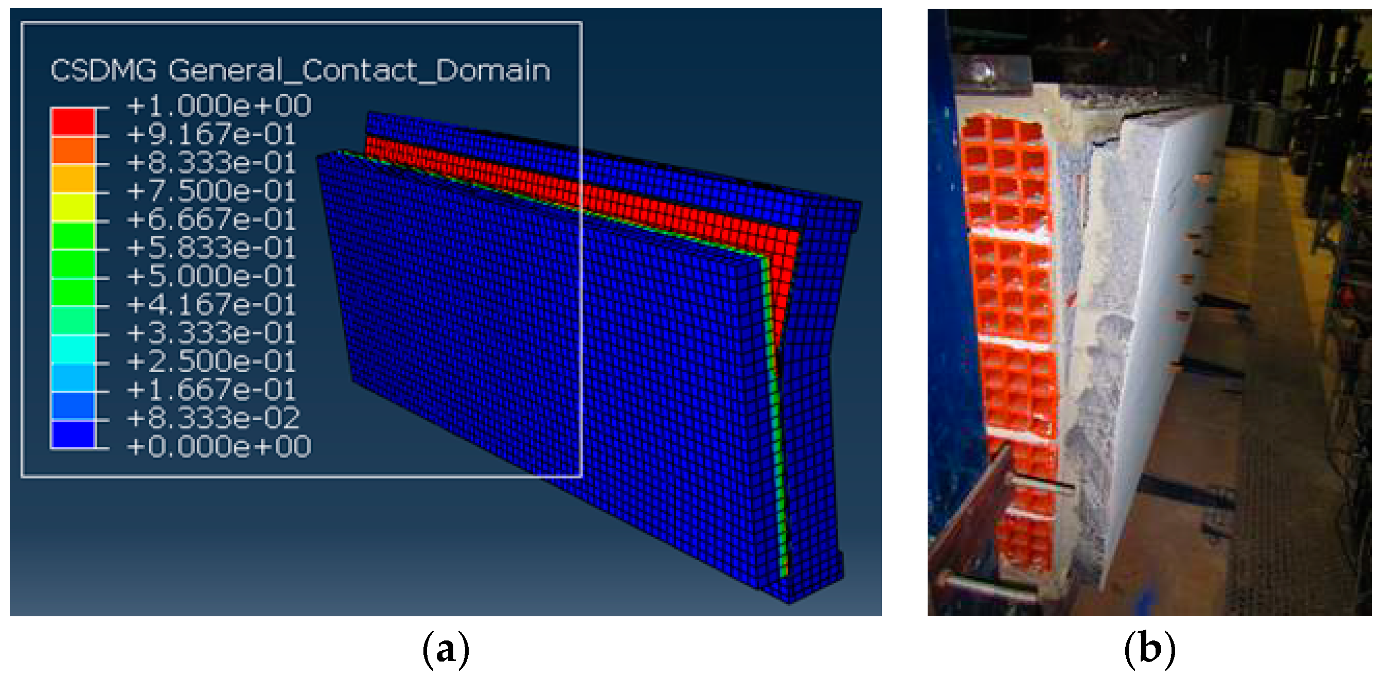
6.1.3. Numerical Simulation of the Out-of-Plane Behavior of the Masonry Wallet with Thermo-Insulating Attachment Made of Expanded Polystyrene (“EPS” with a Thickness of 100 mm)

Figure 23 depicts the numerical out-of-plane response in terms of applied horizontal load versus corresponding horizontal displacement at mid-height of this specimen which has a 100 mm thick thermo-insulating attachment of expanded polystyrene. Figure 23a-left depicts the numerical out-of-plane response in terms of applied horizontal load versus corresponding horizontal displacement at mid-height of this specimen whereas Figure 23b-right shows the numerical out-of-plane displacement profiles along a vertical cross-section (for either compressive or tensile force). In the same figures, the corresponding measurements are also shown. As can be seen, reasonably good agreement is reached between the numerically predicted value (−21.99kN) and the observed (−35.69kN) minimum compressive load.
The numerically predicted displacement response, as noted before for the mineral wool specimens, appears to be less flexible than the corresponding measured response (Figure 21b-right). Again, this must be attributed to the fact that the plotted measured response was preceded by at least two cycles of smaller amplitudes than the ones plotted here, which may have contributed to this observed flexibility. Despite this, the numerical response portrays quite accurately the observed degradation of the bearing flexural capacity that is characterized by a considerable increase of the out-of-plane displacement with a significant decrease (in terms of absolute values) in the corresponding out-of-plane load. In these figures, the numerically predicted response for the tensile load (9.51 kN) shows similar trends with the measured values (4.95 kN) as this tensile load is significant smaller, in terms of absolute values, than the compressive load. The contribution of the thermo-insulating attachment, when in compression, seems to be taken into account even in this limited way.
Figure 24a (left) depicts the accumulation of the loss of contact at the interface between the masonry and the numerical simulation of the thermo-insulation as predicted beyond the stage where the minimum compressive load was applied. Figure 24b (right) shows the observed debonding type of damage for the same masonry wallet with 100 mm thick expanded polystyrene when during testing the applied load was significantly decreased (in terms of absolute values), as compared to the minimum compressive load.

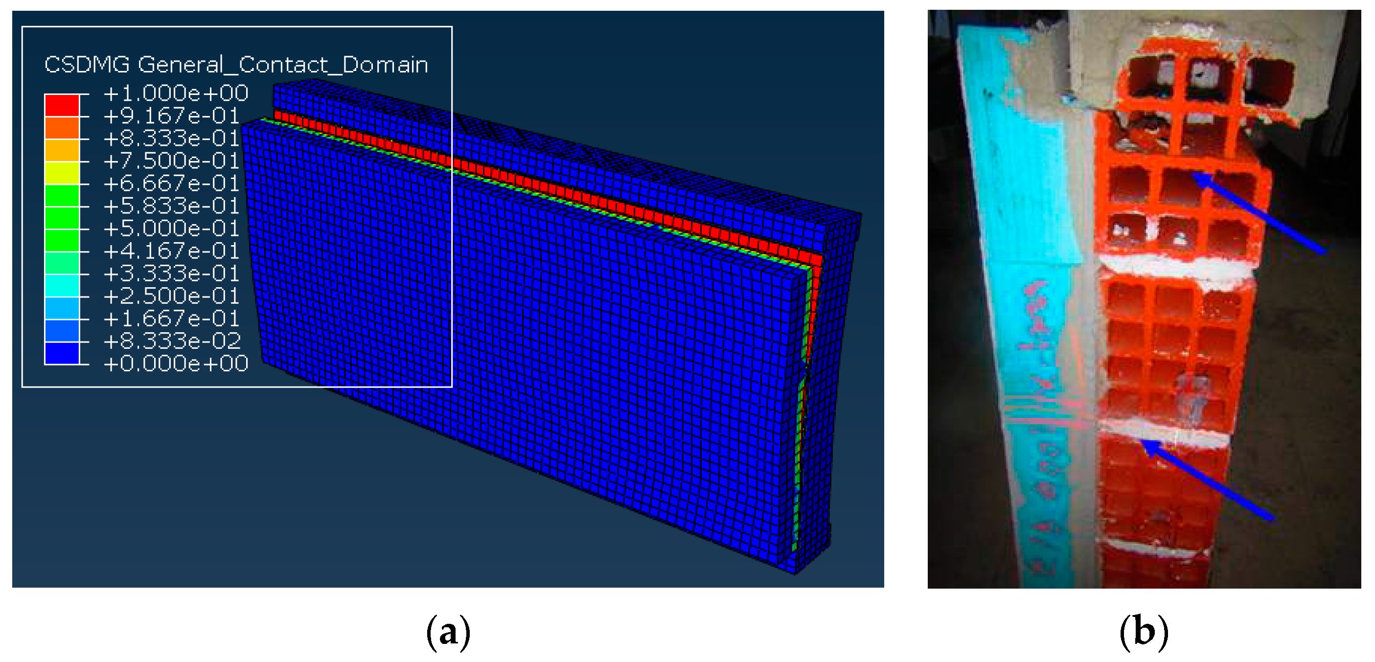
6.1.4. Numerical Simulation of the Out-of-Plane Behavior of the Masonry Wallet with Thermo-Insulating Attachment Made of Extruded Polystyrene (“XPS” with a Thickness of 100 mm)

Figure 25 depicts the numerical out-of-plane response in terms of applied horizontal load versus corresponding horizontal displacement at mid-height of this specimen which has a thermo-insulating attachment of extruded polystyrene 100 mm thick. Figure 25a-left depicts the numerical out-of-plane response in terms of applied horizontal load versus corresponding horizontal displacement at mid-height of this specimen whereas Figure 25b-right shows the numerical out-of-plane displacement profiles along a vertical cross-section (for either compressive or tensile force). In the same figures, the corresponding measurements are also shown. As can be seen, reasonably good agreement is reached between the numerically predicted value (−32.33 kN) and the observed (−38.91 kN) minimum compressive load. The numerically predicted displacement response of this extruded polystyrene specimen appears to agree with the corresponding measured response (Figure 25b-right). The numerical response portrays quite accurately the observed degradation of the bearing flexural capacity that is characterized by a considerable increase of the out-of-plane displacement with a significant decrease (in terms of absolute values) of the corresponding out-of-plane load. In Figure 26b-right the measured out-of-plane displacement profile of the wallet at the initiation and propagation of the debonding at the upper part is also plotted. It is evident that the combination of the flexural cracks of the mortar bed-joints at mid-height of the masonry with the initiation of the debonding of the thermo-insulation increases the out-of-plane displacement response. In these figures, the numerically predicted response for the tensile load (10.34 kN) shows similar trends with the measured values (14.86 kN) as this tensile load is significantly smaller (in terms of absolute values) than the compressive load.
Figure 26a (left) depicts the accumulation of the loss of contact at the interface between the masonry and the numerical simulation of the thermo-insulation as predicted beyond the stage where the minimum compressive load was applied. Figure 26b (right) shows the observed debonding type of damage for the same masonry wallet with 100 mm thick extruded polystyrene specimen during testing when the applied load was significantly decreased (in terms of absolute values), as compared to the minimum compressive load. It must be underlined that for this XPS masonry wallet the propagation of the debonding of the thermo-insulation from the masonry was accompanied by the breaking of the clay bricks close to the upper boundary, as is shown in Figure 26b-right. This type of failure was not numerically simulated, and this fact may partly explain the differences that can be seen between the numerically predicted and the measured out-of-plane load versus displacement responses shown in Figure 25a,b.
The behavior of four wallets, one of “bare” masonry and the other three having 100 mm thick thermo-insulating facades (extruded polystyrene-XPS, expanded polystyrene EPS, or mineral wool MW), which were included in Figure 19a, Figure 21a, Figure 23a, and Figure 25a, is summarized in Figure 27a,b. These figures depict the out-of-plane response of horizontal displacement at mid-height versus the applied horizontal load for masonry wallets without or with thermo-insulating attachment (XPS, EPS or MW 100 mm thick). On the left side of this figure the numerical predictions are depicted, whereas on the right side the corresponding experimental measurements are shown.
Table 7 summarizes the numerically predicted and measured behavior of these four wallets under compressive out-of-plane load, without or with thermo-insulating facades whereby these attachments are under tension, in terms of maximum absolute value of the applied compressive load and the corresponding out-of-plane displacement values at mid-height. In the same table, the corresponding increase in the flexural capacity of these wallets due to the addition of the thermo-insulating attachments is also listed (see Table 4). The following underline the main observations.
-
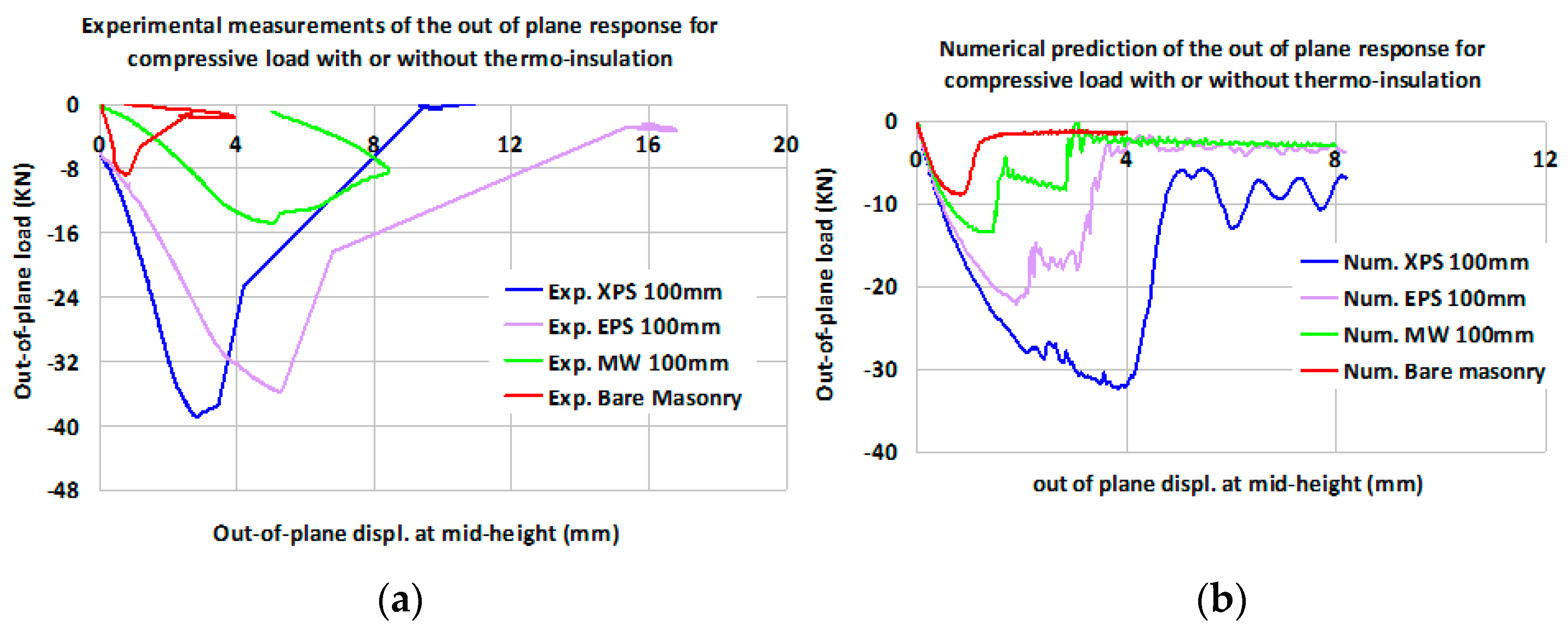
The measured increase in the flexural capacity resulting from the addition of thermo-insulating facades is reasonably well predicted by the employed numerical simulation together with predicting the debonding mode of failure and the resulting decrease in the flexural bearing capacity as was measured during testing.
-
In all cases the measured out-of-plane flexibility of the tested wallets was larger than the one resulting from the numerical predictions. This is evident in all figures where the measured out-of-plane response is compared to the corresponding numerical predictions. This is also evident from the listed displacement values at peak load listed in Table 7 and must be partly attributed to the fact that the numerical analyses did not simulate the cyclic load reversals of the loading laboratory sequence and the corresponding gradual accumulation of micro-cracking and plastic deformations that occurred during the experiments. This issue is currently under study.
-
These observations are relevant only for the case that the direction of the out-of-plane loads result in a flexural behavior whereby the thermo-insulating attachments are under tension. As already discussed, based on the presented experimental evidence, when the direction of the out-of-plane loads subject the thermo-insulating attachments to compression the resulting flexural capacity increase is much smaller than when these thermo-insulation attachments are in tension. This experimental observation was also confirmed by the numerical predicted behavior.
-
Based on the above observations, it can be concluded that the employed numerical simulation, despite its limitations, yields reasonably realistic predictions of the bearing flexural capacity. It must be noted that this numerical simulation utilized all the necessary information relevant to the mechanical properties of all the employed materials as well as the necessary mechanical characteristics that govern the behavior at the contact surface between brick masonry, adhesive mortar and thermo-insulating panels.
-
Certain discrepancies between the peak measured flexural capacity and the one numerically predicted can be seen for the wallet having as thermo-insulating attachment the one constructed with extruded polystyrene (XPS 100 mm). This discrepancy was attributed to the local breaking of the clay cricks at the upper boundary of this wallet together with the initiation of the debonding, which resulted in a decrease of the bearing capacity. This underlines the importance of the boundary conditions and the performance of the masonry substrate at its peripheral supports. It also underlines the necessity in numerically simulating actual conditions. This very important issue is currently under study.

7. Discussion of the Outcome of the Current Study

The following discussion focuses on whether the out-of-plane flexural performance of a masonry facade with such a thermo-insulating attachment, is made less or more vulnerable to seismic loads than the performance of the same masonry prior to installing a certain type of thermo-insulation. This is done by comparing the measured flexural behavior of the tested specimens with thermal insulation to that without, as presented in Section 5. Another point of interest is to discuss the observed limit state of the thermo-insulation when the host masonry is subjected to out-of-plane flexural loads. The following summarize the most important observations:
-
The addition of thermo-insulating attachments resulted in an improved out-of-plane flexural behavior of the tested masonry wallets compared to the masonry wallet without any such attachment. This was demonstrated by the measured increase of the peak out-of-plane load bearing capacity and of the corresponding deformability of the tested specimens having such thermo-insulating attachments. This increase was quite substantial when the direction of the out-of-plane loads was subjecting these thermo-insulating facades to tension. When, for the reverse load direction, these facades were subjected to compression the observed performance improved to a much lesser degree.
-
For most cases, the prevailing mode of failure was the partial debonding of the thermo-insulating facades at their interface with the masonry substrate, being preceded by cracking of the horizontal mortar bed-joints at mid-height. Despite this partial debonding, the presence of the plastic anchors prohibited the total dislocation of these facades from the masonry substrate.
-
The observed improvement of the out-of-plane performance was more substantial for the XPS and EPS facades than for the MW facades. Moreover, an increase in the thickness of the thermo-insulating facade from 50 to 100 mm resulted in a noticeable improvement of the out-of-plane flexural performance. However, the increase in this way of the flexural capacity in terms of peak out-of-plane load resulted in the development of local breaking of the masonry at the supports, due to weakness of the used clay bricks. This type of damage limited any further improvement of the flexural capacity. This fact underlines the importance of investigating the capacity of the masonry substrate and the influence of its boundary conditions at the supports of such masonry facades prior to attaching the thermo-insulation attachments.
The measured response was utilized to form realistic numerical simulations of the observed behavior. The following summarize the most significant observations.
-
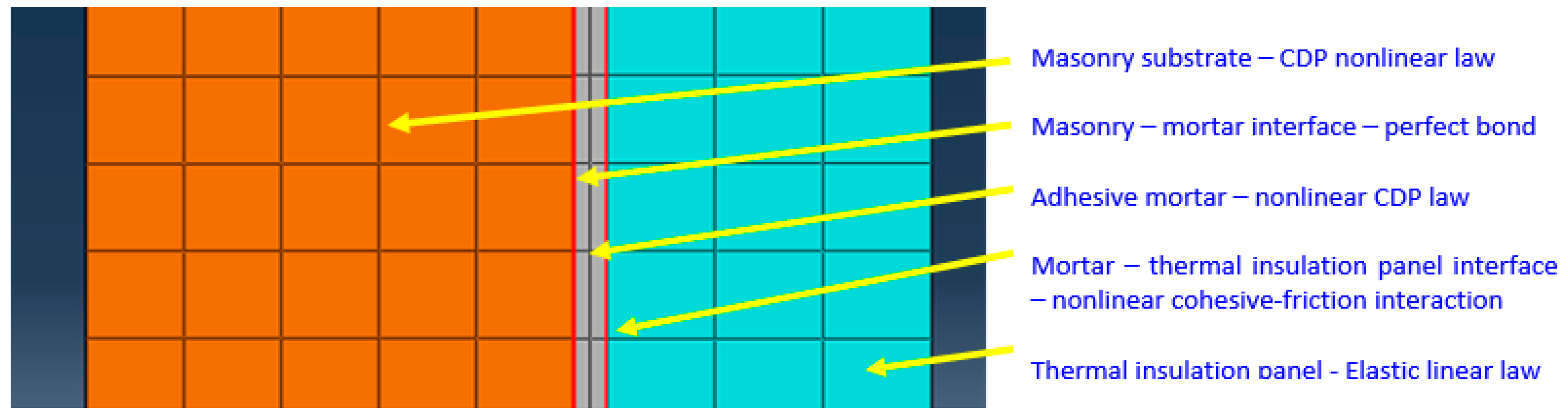
The employed numerical simulation proposes a multi-stage procedure employing basic information obtained from laboratory testing. Initially, a valid numerical simulation is formed for the “bare” masonry wallet. Next, this numerical simulation is extended to include the thermo-insulating attachment, utilizing in the subsequent non-linear analysis the obtained in the laboratory mechanical properties of the adhesive mortar and the thermo-insulating materials and their interaction. In this way, the non-linear analysis included realistic constitutive laws describing the interaction between the adhesive mortar interface with the masonry substrate and with the thermo-insulating panel-units. This procedure is of a general nature and can be employed for applications addressing different masonry or thermo-insulating materials.
-
From the comparison of the numerical predictions with the corresponding measurements, it can be concluded that a reasonable agreement can be reached for the flexural capacity, in terms of peak value for the applied out-of-plane load as well as for the observed debonding mode of failure. The better improvement of the flexural capacity of the XPS facade than that of the MW facade, which was observed during testing, was confirmed by the numerical predictions. These numerical simulations neither reproduced the observed out-of-plane flexural flexibility nor the local breaking of the masonry of the tested wallets. These issues should be addressed by future research.

8. Conclusions

(a1) The used thermo-insulating panels, although finally debonded from the masonry substrate, do not collapse, even when the masonry panel develops large out-of-plane displacements, due to the protective action of the used plastic anchors. This may be considered as an acceptable performance for a thermo-insulating attachment when the masonry substrate is subjected to such out-of-plane flexure.
(b1) The presence of such thermo-insulating attachments leads to a considerable increase of the out-of-plane flexural capacity and to a less brittle behavior than the one without this thermo-insulation, when the direction of the out-of-plane loads subjects the thermo-insulating facades to tension. Consequently, this may also lead to a less vulnerable seismic performance than that of the same masonry panel without this thermo-insulating attachment, although further validation is needed considering the influence of the boundary and support conditions of such masonry facades. However, this increase is not as good when the out-of-plane loads subject these thermo-insulating facades to compression.
(c1) The employed in the numerical simulation non-linear response at the interface between the adhesive mortar and the thermo-insulating panels was a key factor for approximating the observed performance. Another key factor was the successful approximation of the non-linear response of the masonry substrate employing the described numerical approach. Both these numerical approximations were based on independent laboratory measurements. The good agreement with observed performance as well as the general nature of this numerical simulation confirms its validity.
(d1) The above conclusions of the present study for the out-of-plane performance of masonry panels, having this particular type of thermo-insulating attachments that was investigated, agree with similar conclusions drawn before [49] for the in-plane performance. It can thus be stated that attaching thermo-insulating facades, similar to the ones studied here, improves the out-of-plane flexural performance as well as the in-plane performance of the masonry substrate, provided that there are not inherent weaknesses of the masonry substrate.
(e1) It must be underlined here that the present investigation is limited in assessing the contribution of the examined thermo-insulating attachments on a given relatively weak masonry substrate. As shown by many researchers, there are many available retrofitting techniques that can effectively upgrade the in-plane and out-of-plane seismic performance of a weak masonry substrate when this is the main objective and not the thermo-insulation. Moreover, it is an objective of future research to study more effective ways of combining seismic strengthening with thermo-insulation. It is hoped that the employed tools and the reported results of the current work will be useful towards such an objective.

Author Contributions

All the members of the research group of Aristotle University (G.C.M., L.M., K.K. and L.K.) were responsible for the design, the execution, the data analysis of the experiments, the design, the execution, the data analysis of the numerical investigation and the observations and the conclusions drawn. A.A. and C.C. were involved in the design of the test specimens and in providing the necessary engineering information related to the application of thermo-insulating facades. All authors were involved in reviewing the final observations. All authors have read and agreed to the published version of the manuscript.

Funding

Co-financed by the Greek Ministry of Economy and Development, General Secretariat of ERDF & CF and the European Union, European Regional Development Fund, ESPA 2014-2020.

Institutional Review Board Statement

Not required.

Informed Consent Statement

Not applicable.

Data Availability Statement

Any additional information may be requested by the authors.

Acknowledgments

All materials for the construction of the specimens were provided by “FIBRAN Anastasiadis Dimitrios S.A.” Part of the aforementioned research “Intelligent Facades for Nearly Zero Energy Buildings (IF–ZEB)” has been co-funded by Greece and European Union through the Operational Program “Erevno-Dimiourgo-Kainotomo” (project code: Τ1EDK-02045) which are gratefully acknowledged.

Conflicts of Interest

The authors declare no conflict of interest.

References

  1. Modena, C.; Casarin, F.; da Porto, F.; Munari, M. L’Aquila 6th April 2009 Earthquake: Emergency and Post-emergency Activities on Cultural Heritage Buildings. Earthquake Engineering in Europe. In Geotechnical, Geological, and Earthquake Engineering; Springer Science + Business Media B.V.: Berlin, Germany, 2010; Volume 17, Chapter 20. [Google Scholar] [CrossRef]
  2. D’Ayala, D.; Dolce, M. Guest editorial: L’Aquila earthquake: Seismic sequence of 6th April 2009, Abruzzo, Italy. Bull. Earthq. Eng. 2011, 9, 1–10. [Google Scholar] [CrossRef]
  3. Manos, G. Consequences on the urban environment in Greece related to the recent intense earth-quake activity. Int. J. Civ. Eng. Archit. 2011, 5, 1065–1090. [Google Scholar]
  4. Papazachos, C.; Pavlides, S.; Chatzipetros, A.; Papathanassiou, G.; Valkaniotis, S.; Pitilakis, D.; Rouchotas, L. GEER/EERI/ATC Earthquake Reconnaissance, January 26th/February 2nd, 2014 Cephalonia, Greece Events. Version 1: June 6, 2014; GEER-EERI-ATC-Report; Edinburgh Napier University: Edinburgh, UK, 2014. [Google Scholar]
  5. Manos, G.C. The 30th of October Samos-Greece Earthquake. Issues relevant to the protection of structural damaged caused by strong earthquake ground motions. J. Archit. Eng. 2020, 5. [Google Scholar] [CrossRef]
  6. Holmes, M. Steel Frames with Brickwork and Concrete Infilling. Proc. Inst. Civ. Eng. 1961, 19, 473–478. [Google Scholar] [CrossRef]
  7. Holmes, M. Combined Loading on Infilled Frames. Proc. Inst. Civ. Eng. 1963, 25, 31–38. [Google Scholar] [CrossRef]
  8. Bryan, S.S. Behaviour of Square Infilled Frames. J. Struct. Div. ASCE 1966, 92, 381–404. [Google Scholar]
  9. Mallick, D.V.; Severn, R.T. The behaviour of infilled frames under static loading. Proc. Inst. Civ. Eng. 1967, 38 Pt 2, 639–656. [Google Scholar] [CrossRef]
  10. Stafford Smith, B.; Carter, C. A Method of Analysis for Infilled Frames. Inst. Civ. Eng. ICE 1969, 44, 31–48. [Google Scholar] [CrossRef]
  11. Mainstone, R.J. Supplementary Note on the Stiffnesses and Strengths of Infilled Frames; Current Paper CP 13/74; Building Research Station: Lahore, Pakistan, 1974. [Google Scholar]
  12. Klingner, R.E.; Bertero, V.V. Infilled Frames in Earthquake-Resistant Construction; EERC, Report No. 76-32; University of California: Berkeley, CA, USA, 1976. [Google Scholar]
  13. Dhanasekar, D.; Page, A.W. The influence of brick masonry infill properties on the behaviour of infilled frames. Proc. Inst. Civ. Eng. 1986, 81 Pt 2, 593–605. [Google Scholar]
  14. Zarnic, R.; Tomazevic, M. The Behaviour of Masonry Infilled Reinforced Concrete Frames Subjected to Cyclic Lateral Loading. In Proceedings of the Eighth World Conference on Earthquake Engineering, San Francisco, CA, USA, 21–28 July 1984. [Google Scholar]
  15. Styliniades, K. Experimental Investigation of the Behaviour of Single-Story Infilled R/C Frames under Cyclic Quasi-Static Horizontal Loading (Parametric Analysis). Ph.D. Thesis, Department of Civil Engineering, Aristotle University of Thessaloniki, Thessaloniki, Greece, 1985. [Google Scholar]
  16. Carydis, P.G.; Mouzakis, H.P.; Taflambas, J.M.; Vougioukas, E.A. Response of infilled frames with brickwalls to earthquake motions. In Proceedings of the 10th World Conference Earthquake Engineering, Madrid, Spain, 19–24 July 1992; pp. 2829–2834. [Google Scholar]
  17. Buonopane, S.G.; White, R.N. Pseudodynamic testing of masonry infilled reinforced concrete frame. J. Struct. Eng. 1999, 578–589. [Google Scholar] [CrossRef]
  18. Chiou, Y.C.; Tzeng, J.-C.; Liou, Y.W. Experimental and analytical study of Masonry Infilled Frames. J. Struct. Engrg. ASCE 1999, 125, 1109–1116. [Google Scholar] [CrossRef]
  19. Soulis, V. Investigation of the Numerical Simulation of Masonry Infilled R/C Frame Structures under Seismic Type Loading. Ph.D. Thesis, Department of Civil Engineering, Aristotle University of Thessaloniki, Thessaloniki, Greece, 2009. [Google Scholar]
  20. Thauampteh, J. Experimental Investigation of the Behaviour of Single-Story R/C Frames Infills, Virgin and Repaired, under Cyclic Horizontal Loading. Ph.D. Thesis, Department of Civil Engineering, Aristotle University of Thessaloniki, Thessaloniki, Greece, 2009. [Google Scholar]
  21. Da Porto, F.; Guidi, G.; Garbin, G.; Modena, C. In-plane behaviour of clay masonry walls: Experimental testing and finite element modelling. ASCE J. Struct. Eng. 2010, 136, 1379–1392. [Google Scholar] [CrossRef]
  22. Asteris, P.G. Special Issue on Infilled Framed Structures. Open Constr. Build. Technol. J. 2012, 6 (Suppl. 1), 32. [Google Scholar]
  23. Kadhim, J.A.; Dawood, A.O. Seismic Performance of Clay Bricks Construction. Civ. Eng. J. 2020, 6, 785–805. [Google Scholar] [CrossRef]
  24. Rastegarian, S.; Sharifi, A. An Investigation on the Correlation of Inter-story Drift and Performance Objectives in Conventional RC Frames. Emerg. Sci. J. 2018, 2, 140–147. [Google Scholar] [CrossRef]
  25. Umar, M.; Shah, S.A.A.; Shahzada, K.; Naqash, T.; Ali, W. Assessment of Seismic Capacity for Reinforced Concrete Frames with Perforated Unreinforced Brick Masonry Infill Wall. Civ. Eng. J. 2020, 6, 2397–2415. [Google Scholar] [CrossRef]
  26. Rahem, A.; Djarir, Y.; Noureddine, L.; Tayeb, B. Effect of Masonry Infill Walls with Openings on Nonlinear Response of Steel Frames. Civ. Eng. J. 2021, 7, 278–291. [Google Scholar] [CrossRef]
  27. Cavaleri, L.; Zizzo, M.; Asteris, P.G. Residual out-of-plane capacity of infills damaged by in-plane cyclic loads. Eng. Struct. 2020, 209, 109957. [Google Scholar] [CrossRef]
  28. Da Porto, F.; Grendene, M.; Mosele, F.; Modena, C. In-plane cyclic behaviour of load bearing masonry walls. In Proceedings of the 7th International Masonry Conference, London, UK, 30 October–1 November 2006. [Google Scholar]
  29. Ghosh, A.; Amde, A. Finite element analysis of infilled frames. J. Struct. Eng. 2002, 128, 881–889. [Google Scholar] [CrossRef]
  30. Manos, G.C.; Soulis, V.; Thauampteh, J. Nonlinear numerical model and its utilization in simulating the in-plane behaviour of multi-story R/C frames with masonry infills. Open Constr. Build. Technol. J. 2012, 6 (Suppl. 1-M16), 254–277. [Google Scholar] [CrossRef] [Green Version]
  31. Manos, G.C.; Soulis, V. Simulation of the in-plane seismic behaviour of masonry infills within Multistory Reinforced Concrete Framed Structures. In Proceedings of the 9th International Masonry Conference, Guimaraes, Portugal, 7–9 July 2014. [Google Scholar]
  32. Manos, G.C.; Soulis, V.J.; Thauampteh, J. The behaviour of masonry assemblages and masonry-infilled R/C frames subjected to combined vertical and cyclic horizontal seismic-type loading. Adv. Eng. Softw. 2012, 45, 213–231. [Google Scholar] [CrossRef]
  33. Focardi, F.; Manzini, E. Cyclic and Monotonic Diagonal Tension Tests on Various Shape Reinforced and Non-Reinforced Brick Panels. In Proceedings of the 8th European Conference on Earthquake Engineering, Lisbon, Portugal, 7–12 September 1986; Volume 4. [Google Scholar]
  34. Lourenco, P.B. Computational Strategies for Masonry Structures. Ph.D. Thesis, Delft University of Technology, Delft, The Netherlands, 1996. [Google Scholar]
  35. Lourenco, P.; Rots, J.G. On the Use of Micro-Models for the Analysis of Masonry Shear-Walls; Pande, G.N., Middleton, J., Eds.; Computer Methods in Structural Masonry-2: Swansea, UK, 1993; pp. 14–25. [Google Scholar]
  36. Mehrabi, A.B.; Shing, P. Finite element modelling of masonry-infilled RC frames. J. Struct. Eng. 1997, 123, 604–613. [Google Scholar] [CrossRef]
  37. Lavado, J.L.; Gallardo, C.H. Experimental and numerical analysis of behaviour of old brick masonries. In Proceedings of the 17th World Conference on Earthquake Engineering, Sendai, Japan, 14–18 September 2020. [Google Scholar] [CrossRef]
  38. Janaraj, T.; Dhanasekar, M. Effectiveness of Two Forms of Grouted Reinforced Confinement Methods to Hollow Concrete Masonry Panels. J. Mater. Civ. Eng. 2015, 27, 04015038. [Google Scholar] [CrossRef] [Green Version]
  39. De Carvalho Bello, C.B.; Cecchi, A.; Meroi, E.; Oliveira, D.V. Experimental and numerical investigations on the behaviour of masonry walls reinforced with an innovative sisal FRCM system. Key Eng. Mater. 2017, 747, 190–195. [Google Scholar] [CrossRef]
  40. Rousakis, T.; Ilki, A.; Kwiecien, A.; Viskovic, A.; Gams, M.; Triller, P.; Bogdanovic, A. Deformable polyurethane joints and fibre grids for resilient seismic performance of reinforced concrete frames with orthoblock brick infills. Polymers 2020, 12, 2869. [Google Scholar] [CrossRef] [PubMed]
  41. Bolhassani, M.; Hamid, A.A.; Lau, A.C.W.; Moon, F. Simplified micro modeling of partially grouted masonry assemblages. Constr. Build. Mater. 2015, 83, 159–173. [Google Scholar] [CrossRef]
  42. Arnau, O.; Sandoval, C.; Murià-Vila, D. Determination and validation of input parameters for detailed micro- modelling of partially grouted reinforced masonry walls. In Proceedings of the Tenth Pacific Conference on Earthquake Engineering, Sydney, Australia, 6–8 November 2015; Volume 110. [Google Scholar]
  43. Sandoval, C.; Arnau, O. Experimental characterization and detailed micro-modeling of multi-perforated clay brick masonry structural response. Mater. Struct. 2017, 50, 34. [Google Scholar] [CrossRef]
  44. Malomo, D.; DeJong, M.J.; Penna, A. A Homogenized Distinct Macro-Block (HDM) Model for Simulating the In-Plane Cyclic Response of URM Walls. In Proceedings of the 13th North American Masonry Conference, Salt Lake, UT, USA, 16–19 June 2019; Volume 1, pp. 1042–1054. [Google Scholar]
  45. Domede, N.; Sellier, A. Experimental and numerical analysis of behaviour of old brick masonries. Adv. Mater. Res. 2010, 133–134, 307–312. [Google Scholar] [CrossRef]
  46. EN 1998-1/2005-05-12. Eurocode 8: Design of Structures for Earthquake Resistance—Part1: General Rules, Seismic Actions and Rules for Buildings. Available online: https://www.saiglobal.com/PDFTemp/Previews/OSH/IS/EN/2005/I.S.EN1998-1-2005.pdf (accessed on 2 August 2021).
  47. La Greca, P.; Margani, G. Seismic and energy renovation measures for sustainable cities: A critical analysis of the Italian scenario. Sustainability 2018, 10, 254. [Google Scholar] [CrossRef] [Green Version]
  48. Leone, M.F.; Zuccaro, G. Seismic and Energy Retrofitting of Residential Buildings: A Simulation—Based Approach. UPLanD 2016, 1, 11–25. [Google Scholar]
  49. Manos, G.C.; Melidis, L.; Katakalos, K.; Kotoulas, L.; Anastasiadis, A.; Chatziastrou, C. Masonry panels with external thermal insulation subjected to in-plane diagonal compression. Case Stud. Constr. Mater. 2021, 14, e00538. [Google Scholar] [CrossRef]
  50. Antoniadou, P.; Symeonidou, M.; Kyriaki, E.; Giama, E.; Boemi, S.N.; Chadiarakou, S.; Papadopoulos, A.M. High performance building façades for Zero Energy Buildings in Greece: State of the art and perspectives. IOP Conf. Ser. Earth Environ. Sci. 2020, 410, 012036. [Google Scholar] [CrossRef]
  51. Papadopoulos, A.M. State of the art in thermal insulation materials and aims for future developments. Energy Build. 2005, 37, 77–86. [Google Scholar] [CrossRef]
  52. Touloupaki, E.; Theodosiou, T. Optimization of external envelope insulation thickness: A parametric study. Energies 2017, 10, 270. [Google Scholar] [CrossRef] [Green Version]
  53. Norvaišienė, R.; Buhagiar, V.; Burlingis, A.; Miškinis, K. Investigation of mechanical resistance of external thermal insulation composite systems (ETICS). J. Build. Eng. 2020, 32, 101682. [Google Scholar] [CrossRef]
  54. Uygunoğlu, T.; Özgüven, S.; Çalış, M. Effect of plaster thickness on performance of external thermal insulation cladding systems (ETICS) in buildings. Constr. Build. Mater. 2016, 122, 496–504. [Google Scholar] [CrossRef]
  55. Bournas, D.A. Concurrent seismic and energy retrofitting of RC and masonry building envelopes using inorganic textile-based composites combined with insulation materials: A new concept. Compos. Part B Eng. 2018, 148, 166–179. [Google Scholar] [CrossRef]
  56. Triantafillou, T.C.; Karlos, K.; Kapsalis, P.; Georgiou, L. Innovative Structural and Energy Retrofitting System for Masonry Walls Using Textile Reinforced Mortars Combined with Thermal Insulation: In-Plane Mechanical Behaviour. J. Compos. Constr. 2018, 22, 04018029. [Google Scholar] [CrossRef]
  57. Gkournelos, P.D.; Triantafillou, T.C.; Bournas, D.A. Integrated Structural and Energy Retrofitting of Masonry Walls: Effect of In-Plane Damage on the Out-of-Plane Response. J. Compos. Constr. 2020, 24, 04020049. [Google Scholar] [CrossRef]
  58. Borri, A.; Corradi, M.; Sisti, R.; Buratti, C.; Belloni, E.; Moretti, E. Masonry wall panels retrofitted with thermal-insulating GFRP-reinforced jacketing. Mater. Struct. 2016, 49, 3957–3968. [Google Scholar] [CrossRef] [Green Version]
  59. Manos, G.; Katakalos, K.; Melidis, L.; Anastasiadis, A. The behaviour of masonry infills with thermal insulation facades under out of plane seismic type loads (In Greek). In Proceedings of the 4th Panhellenic Conference on Earthquake Engineering and Technical Seismology, Athens, Greece, 5–7 September 2019. [Google Scholar]
  60. Manos, G.; Melidis, L.; Katakalos, K.; Soulis, V.; Anastasiadis, A. Unreinforced masonry with thermal insulation facades in multi-story buildings subjected to seismic type loads. In Proceedings of the 17th World Conference on Earthquake Engineering, Sendai, Japan, 13–18 September 2020. [Google Scholar]
  61. Pohoryles, D.A.; Maduta, C.; Bournas, D.A.; Kouris, L.A. Energy performance of existing residential buildings in Europe: A novel approach combining energy with seismic retrofitting. Energy Build. 2020, 223, 110024. [Google Scholar] [CrossRef]
  62. Gattesco, N.; Boem, I. Experimental and analytical study to evaluate the effectiveness of an in-plane reinforcement for masonry walls using GFRP meshes. Constr. Build. Mater. 2015, 88, 94–104. [Google Scholar] [CrossRef]
  63. Gattesco, N.; Amadio, C.; Bedon, C. Experimental and numerical study on the shear behaviour of stone masonry walls strengthened with GFRP reinforced mortar coating and steel-cord reinforced repointing. Eng. Struct. 2015, 90, 143–157. [Google Scholar] [CrossRef] [Green Version]
  64. Thomoglou, A.K.; Rousakis, T.C.; Achillopoulou, D.V.; Karabinis, A.I. Ultimate Shear Strength Prediction Model for Unreinforced Masonry Retrofitted Externally with Textile Reinforced Mortar. Earthq. Struct. 2020, 19, 411–425. [Google Scholar] [CrossRef]
  65. Jafari, A.; Oskouei, A.V.; Bazli, M.; Ghahri, R. Effect of the FRP sheet’s arrays and NSM FRP bars on in-plane behaviour of URM walls. J. Build. Eng. 2018, 20, 679–695. [Google Scholar] [CrossRef]
  66. Thomoglou, A.; Rousakis, T.; Karabinis, A. Numerical Modeling of Shear Behavior of Urm Strengthened with Frcm or Frp Subjected to Seismic loading. In Proceedings of the 16th European Conference on Earthquake Engineering, Thessaloniki, Greece, 18–21 June 2018; pp. 1–10. [Google Scholar]
  67. Spyrakos, C.C.; Maniatakis, C.A.; Psycharis, I.N.; Smyarou, E.; Asteris, P.G. Validation of analytical models for the assessment of brick-infilled RC frames strengthened with FRPs. In Proceedings of the 4th ECCOMAS Thematic Conference on Computational Methods in Structural Dynamics and Earthquake Engineering, Kos Island, Greece, 12–14 June 2013; pp. 2978–2996. [Google Scholar] [CrossRef] [Green Version]
  68. Derakhshan, H.; Dizhur, D.; Griffith, M.C.; Ingham, J.M. In Situ Out-of-Plane Testing of As-Built and Retrofitted Unreinforced Masonry Walls. J. Struct. Eng. 2014, 140, 04014022. [Google Scholar] [CrossRef] [Green Version]
  69. Reboul, N.; Si Larbi, A.; Ferrier, E. Two-way bending behaviour of hollow concrete block masonry walls reinforced by composite materials. Compos. Part B Eng. 2018, 137, 163–177. [Google Scholar] [CrossRef]
  70. D’Ambrisi, A.; Mezzi, M.; Caporale, A. Experimental investigation on polymeric net-RCM reinforced masonry panels. Compos. Struct. 2013, 105, 207–215. [Google Scholar] [CrossRef]
  71. Sagar, S.L.; Singhal, V.; Rai, D.C.; Gudur, P. Diagonal shear and out-of-plane flexural strength of fabric-reinforced cementitious matrix-strengthened masonry walletes. J. Compos. Constr. 2017, 21, 04017016. [Google Scholar] [CrossRef]
  72. Babaeidarabad, S.; De Caso, F.; Nanni, A. Out-of-Plane Behavior of URM Walls Strengthened with Fabric-Reinforced Cementitious Matrix Composite. J. Compos. Constr. 2014, 18, 04013057. [Google Scholar] [CrossRef]
  73. Kariou, F.A.; Triantafyllou, S.P.; Bournas, D.A.; Koutas, L.N. Out-of-plane response of masonry walls strengthened using textile-mortar system. Constr. Build. Mater. 2018, 165, 769–781. [Google Scholar] [CrossRef] [Green Version]
  74. D’Ambra, C.; Lignola, G.P.; Prota, A.; Sacco, E.; Fabbrocino, F. Experimental performance of FRCM retrofit on out-of-plane behaviour of clay brick walls. Compos. Part B Eng. 2018, 148, 198–206. [Google Scholar] [CrossRef]
  75. Thermou, G.E.; Katakalos, K.; Manos, G. Influence of the loading rate on the axial compressive behavior of concrete specimens confined with SRG jackets. In Proceedings of the 4th International Conference on Computational Methods in Structural Dynamics and Earthquake Engineering, Kos Island, Greece, 12–14 June 2013; pp. 1107–1122. [Google Scholar] [CrossRef] [Green Version]
  76. Thermou, G.E.; Katakalos, K.; Manos, G. Concrete confinement with steel-reinforced grout jackets. Mater. Struct. 2015, 48, 1355–1376. [Google Scholar] [CrossRef]
  77. Banerjee, S.; Nayak, S.; Das, S. Shear and flexural behaviour of unreinforced masonry wallets with steel wire mesh. J. Build. Eng. 2020, 30, 101254. [Google Scholar] [CrossRef]
  78. Willis, C.R.; Seracino, R.; Griffith, M.C. Out-of-plane strength of brick masonry retrofitted with horizontal NSM CFRP strips. Eng. Struct. 2010, 32, 547–555. [Google Scholar] [CrossRef]
  79. Dizhur, D.; Griffith, M.; Ingham, J. Out-of-plane strengthening of unreinforced masonry walls using near surface mounted fibre reinforced polymer strips. Eng. Struct. 2014, 59, 330–343. [Google Scholar] [CrossRef]
  80. Türkmen, S.; Wijte, S.N.M.; De Vries, B.T.; Ingham, J.M. Out-of-plane behavior of clay brick masonry walls retrofitted with flexible deep mounted CFRP strips. Eng. Struct. 2021, 228, 111448. [Google Scholar] [CrossRef]
  81. Gattesco, N.; Boem, I. Out-of-plane behavior of reinforced masonry walls: Experimental and numerical study. Compos. Part B Eng. 2017, 128, 39–52. [Google Scholar] [CrossRef] [Green Version]
  82. Griffith, M.C.; Kashyap, J.; Mohamed Ali, M.S. Flexural displacement response of NSM FRP retrofitted masonry walls. Constr. Build. Mater. 2013, 49, 1032–1040. [Google Scholar] [CrossRef]
  83. Lin, Y.; Lawley, D.; Wotherspoon, L.; Ingham, J.M. Out-of-plane Testing of Unreinforced Masonry Walls Strengthened Using ECC Shotcrete. Structures 2016, 7, 33–42. [Google Scholar] [CrossRef]
  84. Ismail, N.; Ingham, J.M. Cyclic Out-of-Plane Behavior of Slender Clay Brick Masonry Walls Seismically Strengthened Using Posttensioning. J. Struct. Eng. 2012, 138, 1255–1266. [Google Scholar] [CrossRef]
  85. Ismail, N.; Ingham, J.M. In-situ and laboratory based out-of-plane testing of unreinforced clay brick masonry walls strengthened using near surface mounted twisted steel bars. Constr. Build. Mater. 2012, 36, 119–128. [Google Scholar] [CrossRef]
  86. Khan, H.A.; Nanda, R.P. Out-of-plane bending of masonry wallette strengthened with geosynthetic. Constr. Build. Mater. 2020, 231, 117198. [Google Scholar] [CrossRef]
  87. Mishra, C.; Yamaguchi, K.; Endο, Y.; Hanazato, T.; Shakya, M. Study on shear and flexural behavior of Νepalese masonry walls with and without reinforcement. In Proceedings of the 17th World Conference on Earthquake Engineering, Sendai, Japan, 13–18 September 2020. [Google Scholar]
  88. EN1996-1-1:1998 Eurocode 6—Design of Masonry Structures—Part 1-1: General Rules for Reinforced and Unreinforced Masonry Structures. Available online: https://www.phd.eng.br/wp-content/uploads/2015/02/en.1996.1.1.2005.pdf (accessed on 2 August 2021).
  89. EN 1015:1999 Methods of Test for Mortar for Masonry—Part 11: Determination of Flexural and Compressive Strength of Hardened Mortar. Available online: https://standards.iteh.ai/catalog/standards/cen/251c5fb4-ef60-4285-9039-be39d56242d3/en-1015-11-1999-a1-2006 (accessed on 2 August 2021).
  90. EN 772-1: 2011—Methods of Test for Masonry Units—Part 1: Determination of Compressive Strength. Available online: https://standards.iteh.ai/catalog/standards/cen/e16d7005-8730-4382-9a9d-4d351d00f981/en-772-1-2011 (accessed on 2 August 2021).
  91. EN 826:2013—Thermal Insulating Products for Building Applications. Determination of Compression Behaviour. Available online: https://standards.iteh.ai/catalog/standards/cen/f54055a6-cacc-4d69-b85a-b190aea8ed7f/en-826-2013 (accessed on 2 August 2021).
  92. EN 1607:2013—Thermal Insulating Products for Building Applications. Determination of Tensile Strength Perpendicular to Faces. Available online: https://0-shop-bsigroup-com.brum.beds.ac.uk/ProductDetail?pid=000000000030259091 (accessed on 2 August 2021).
  93. EN 12089:2013—Thermal Insulating Products for Building Applications—Determination of Bending Behaviour. Available online: https://0-shop-bsigroup-com.brum.beds.ac.uk/ProductDetail?pid=000000000030259152 (accessed on 2 August 2021).
  94. EN 12090:2013—Thermal Insulating Products for Building Applications. Determination of Shear Behaviour. Available online: https://0-shop-bsigroup-com.brum.beds.ac.uk/ProductDetail/?pid=000000000030259140 (accessed on 2 August 2021).
  95. EN 1542:1999—Products and Systems for the Protection of Concrete Structures- Test Methods—Measurements of Bond Strength by Pull-Off. Available online: https://0-shop-bsigroup-com.brum.beds.ac.uk/ProductDetail?pid=000000000019972442 (accessed on 2 August 2021).
  96. Asteris, P.G.; Antoniou, S.T.; Sophianopoulos, D.S.; Chrysostomou, C.Z. Mathematical Macromodeling of Infilled Frames: State of the Art. J. Struct. Eng. 2011, 137, 1508–1517. [Google Scholar] [CrossRef]
  97. Asteris, P.G.; Cotsovos, D.M.; Chrysostomou, C.Z.; Mohebkhah, A.; Al-Chaar, G.K. Mathematical micromodeling of infilled frames: State of the art. Eng. Struct. 2013, 56, 1905–1921. [Google Scholar] [CrossRef]
  98. Lourenço, P.B.; De Borst, R.; Rots, J.G. A plane stress softening plasticity model for orthotropic materials. Int. J. Numer. Methods Eng. 1997, 40, 4033–4057. [Google Scholar] [CrossRef]
  99. Noor-E-Khuda, S.; Dhanasekar, M.; Thambiratnam, D.P. Out-of-plane deformation and failure of masonry walls with various forms of reinforcement. Compos. Struct. 2016, 140, 262–277. [Google Scholar] [CrossRef] [Green Version]
  100. Galvez, F.; Segatta, S.; Giaretton, M.; Walsh, K.; Giongo, I.; Dizhur, D. FE and DE modelling of out-of-plane two way bending behaviour of unreinforced masonry walls. In Proceedings of the 16th European Conference on Earthquake Engineering—ECEE, Thessaloniki, Greece, 18–21 June 2018; pp. 1–11. [Google Scholar]
  101. Abaqus Unified FEA—SIMULIA™ by Dassault Systèmes. Available online: https://www.3ds.com/products-services/simulia/products/abaqus/ (accessed on 2 August 2021).
  102. Lubliner, J.; Oliver, J.; Oller, S.; Oñate, E. A plastic-damage model for concrete. Int. J. Solids Struct. 1989, 25, 299–326. [Google Scholar] [CrossRef]
  103. Lee, J.; Fenves, G.L. Plastic-Damage Model for Cyclic Loading of Concrete Structures. J. Eng. Mech. 1998, 124, 892–900. [Google Scholar] [CrossRef]
Figure 1. Collapse of unreinforced masonry facades of multi-story R/C buildings in Duress, Albania (26th November 2019, in-situ visit).
Buildings 11 00335 g001
Figure 2. Collapse of unreinforced masonry facades of multi-story R/C buildings with thermo-insulation schemes located within the gap of a double wythe masonry panel. (Left) L’Aquila, Italy (2009), (right) Athens, Greece (1999) [3].
Buildings 11 00335 g002
Figure 3. Used loading arrangement (steel strong reaction frame) for the out-of-plane flexural performance of masonry wallets with or without thermo-insulating attachments. (a) Vertical cross-section through the axis of symmetry of the masonry wallet with the thermo-insulation where the actuator is attached. (b) View of the facade where the thermo-insulation is attached together with the two vertical cross-sections (East and West) where the installed instrumentation measures the out-of-plane displacement response.
Buildings 11 00335 g003
Figure 4. Used loading arrangement (steel strong reaction frame) for the out-of-plane flexural performance of masonry wallets with or without thermo-insulating attachments. (a) View of the facade without thermo-insulation where the actuator is attached. (b) View of the facade where the thermo-insulation is attached.
Buildings 11 00335 g004
Figure 5. Used sign convention for the applied out-of-plane load.
Buildings 11 00335 g005
Figure 6. Τhe different stages of the ETICS construction: completion of masonry wallet. (a) The pattern of panels and of anchors locations, (b) masonry wallet prior to attaching the thermal insulating panels, (c) final plastering, (d) wallet with mineral wall thermo-insulating attachment, (e) wallets with either EPS or XPS thermal insulating attachments.
Buildings 11 00335 g006
Figure 7. Typical cross-section of a thermal insulated infill wall with details of the used plastic anchor.
Buildings 11 00335 g007
Figure 8. Typical four-point bending of masonry triplets.
Buildings 11 00335 g008
Figure 9. (a) Masonry wallet without any thermo-insulating attachment (Code name WOP0A). (b) Masonry wallet with a mineral wool (MW) facade of 100 mm thickness subjected to out-of-plane flexure (WOPM100A). (c) Masonry wallet with an expanded polystyrene (EPS) facade of 100 mm thickness subjected to out-of-plane flexure (WOPE100A). (d) Masonry wallet with an extruded polystyrene (XPS) facade of 100 mm thickness subjected to out-of-plane flexure (WOPX100B).
Buildings 11 00335 g009
Figure 10. (a-left) “Bare” wallet crack pattern. (b-right) East and West vertical cross-section out-of-plane horizontal displacement profiles for certain distinct stages of the out-of-plane. Horizontal load applied to the “bare” masonry wallet without thermo-insulating attachment.
Buildings 11 00335 g010
Figure 11. (a-left) Masonry wallet with mineral wool attachment initiation of crack pattern. (b-right) East and West vertical cross-section out-of-plane horizontal displacement profiles for certain distinct stages of the out-of-plane horizontal load applied to the masonry wallet with masonry wool thermo-insulating attachment.
Buildings 11 00335 g011
Figure 12. (a-left) Masonry wallet with mineral wool attachment propagation of crack pattern and debonding of mineral wool. (b-right) East and West vertical cross-section out-of-plane horizontal displacement profiles for certain distinct stages of the out-of-plane horizontal load applied to the masonry wallet with mineral wool thermo-insulating attachment.
Buildings 11 00335 g012
Figure 13. (a-left) Masonry wallet with expanded polyester attachment—no damage. (b-right) East and West vertical cross-section out-of-plane horizontal displacement profiles for certain distinct stages of the out-of-plane horizontal load stress applied to the masonry wallet with expanded polyester thermo-insulating attachment.
Buildings 11 00335 g013
Figure 14. (a-left) Masonry wallet with expanded polyester attachment—horizontal cracking at mid height and extensive debonding of EPS at the upper part. (b-right) East and West vertical cross-section out-of-plane horizontal displacement profiles for certain distinct stages of the out-of-plane horizontal load applied to the masonry wallet with expanded polyester thermo-insulating attachment.
Buildings 11 00335 g014
Figure 15. Masonry wallet with extruded polyester attachment. (a-left) Horizontal cracking and debonding at the top. (b-left) Flexural crack at mid-height both at the horizontal bed-joint as well as at the XPS panel. (c-right) East and West vertical cross-section out-of-plane horizontal displacement profiles Test 4. (d-right) East and West vertical cross-section out-of-plane horizontal displacement profiles Test 5. (e-right) East and West vertical cross-section out-of-plane horizontal displacement profiles Test 6.
Buildings 11 00335 g015
Figure 16. Used numerical simulation of the interface between masonry and thermo-insulation.
Buildings 11 00335 g016
Figure 17. Cross-section of a masonry attached with thermal insulation model.
Buildings 11 00335 g017
Figure 18. (a-left) The numerical simulation of the adhesive mortar is depicted with gray color. The area of the masonry substrate not covered with adhesive mortar is shown with orange color. (b-right) The actual area covered by the adhesive mortar from a typical specimen after the removal of the attached thermo-insulation.
Buildings 11 00335 g018
Figure 19. Masonry wallet without thermo-insulating attachment. (a-left) Out-of-plane horizontal displacement at mid-height versus applied horizontal load. (b-right) Out-of-plane horizontal displacement profile along the West vertical cross-section for either minimum compressive or maximum tensile force.
Buildings 11 00335 g019
Figure 20. Masonry wallet without thermo-insulating attachment. (a-left) Accumulated plastic strains as predicted by the numerical simulation. (b-right) Observed damage at a horizontal mortar bed-joint during testing.
Buildings 11 00335 g020
Figure 21. Masonry wallet with thermo-insulating attachment mineral wool (MW) 100 mm thick. (a-left) Out-of-plane horizontal displacement at mid-height versus applied horizontal load. (b-right) Out-of-plane horizontal displacement profile along the West vertical cross-section for either minimum compressive or maximum tensile force.
Buildings 11 00335 g021
Figure 22. Masonry wallet with mineral wool thermo-insulating attachment 100 mm thick. (a-left) Numerically predicted loss of contact strains at the interface between the masonry and the numerical simulation of the thermo-insulation. (b-right) Observed debonding type damage at the top of the tested masonry wallet.
Buildings 11 00335 g022
Figure 23. Masonry wallet with thermo-insulating attachment expanded polystyrene (EPS) 100 mm thick. (a-left) Out-of-plane horizontal displacement at mid-height versus applied horizontal load. (b-right) Out-of-plane horizontal displacement profile along the West vertical cross-section for either minimum compressive or maximum tensile force.
Buildings 11 00335 g023
Figure 24. Masonry wallet with expanded polystyrene thermo-insulating attachment 100 mm thick. (a-left) Numerically predicted loss of contact strains at the interface between the masonry and the numerical simulation of the thermo-insulation. (b-right) Observed debonding type damage at the top of the tested masonry wallet.
Buildings 11 00335 g024
Figure 25. Masonry wallet with thermo-insulating attachment extruded polystyrene (XPS) 100mm thick. (a-left) Out-of-plane horizontal displacement at mid-height versus applied horizontal load. (b-right) Out-of-plane horizontal displacement profile along the West vertical cross-section for either minimum compressive or maximum tensile force.
Buildings 11 00335 g025
Figure 26. Masonry wallet with extruded polystyrene thermo-insulating attachment 100 mm thick. (a-left) Numerically predicted loss of contact strains at the interface between the masonry and the numerical simulation of the thermo-insulation. (b-right) Observed debonding type damage at the top of the tested masonry wallet accompanied with breaking of parts of the clay bricks at this location.
Buildings 11 00335 g026
Figure 27. Out-of-plane horizontal displacement at mid-height versus applied horizontal load for masonry wallets without or with thermo-insulating attachment 100mm thick. (a-left) Numerical simulation predictions. (b-right) Experimental measurements.
Buildings 11 00335 g027
Table 1. Compressive and flexural strength of masonry triplets with mortar joints 10 mm thick.
Measured Masonry Compressive Strength Masonry Compressive Strength
Euro-Code 6 [46]
Measured Masonry Flexural Strength Normal to Bed-Joint (fxk1)
(1)(2)(3)
1.02 MPa0.94 MPa
(for K = 0.35)
Average = 0.168 MPa
(SDV = 0.035 MPa)
Table 2. Bond strength of adhesive mortar.
Bond between the Adhesive Mortar and the Thermal Insulating Panel (Normal to the Facade) (MPa)
MWEPSXPS
Mean = 0.068   SDV = 0.023Mean = 0.105   SDV = 0.012Mean = 0.178   SDV = 0.068
Table 3. Masonry wallets with or without thermo-insulating attachments tested in out-of-plane flexure.
Code NameWOP0AWOPX50
A
WOPX100
B
WOPE50
A
WOPE50
B
WOPE100
A
WOPM100
A
Type of thermo-insulation *NoXPSXPSEPSEPSEPSMW
Thickness (mm)0501005050100100
XPS—extruded polystyrene; EPS—expanded polystyrene; MW—mineral wool; * Attachment placed on one facade of the tested wallet whereas the other facade was left without any attachment.
Table 4. Masonry wallets with or without thermo-insulating attachments tested in out-of-plane flexure.
(1) Code Name/insulation thickness (mm)WOP0A/0 mmWOPX50A/50 mmWOPX100B/100 mmWOPE50A/50 mmWOPE50B/50 mmWOPE100A/100 mmWOPM100A/100 mm
(2) Type of thermal
Insulation *
“Bare”
without
Extruded polystyrene (XPS)Extruded polystyrene (XPS)Expanded polystyrene (EPS)Expanded polystyrene (EPS)Expanded polystyrene (EPS)Mineral wool
(MW)
(3) Minimum “compressive” load (kN)/mid-height displ. (mm) **−8.81 kN/2 mm−44.48 kN/6 mm−38.91 kN/3 mm−25.23 kN/4 mm−27.30 kN/5 mm−35.62 kN/5 mm−14.77 kN/5 mm
(4) Maximum “tensile” load (KN)/mid-height displ. (mm) ***1.01 kN/1.5 mm5.02 kN/2 mm14.86 kN/1.5 mm10.21 kN/1.5 mmNot tested2.45 kN/5 mm5.21 kN/5 mm
(5) Increase (%) in the “compressive” load compared to the control masonry wallet without thermo-insulation *** 0%405%342%186%210%304%68%
(6) Increase in the “tensile” load (compared to “bare” %) ****0%Damaged before by “compression”69%16%Not testedDamaged before by “compression”Damaged before by “compression”
(7) Number of cycles till peak load (“compressive”) is reached/after peak load4/14/17/18/27/16/27/3
(8) Initial stiffness (K0) and/stiffness before reaching peak load (K1) kN/mmK0 = 20K0 = 20/K1 = 10K0 = 24/K1 = 15K0 =20/K1 = 6.7K0 = 24/K1 = 6K0 =20/K1 = 8K0 = 20/K1 = 4
(9) Ratio of mid-height displ. for the peak load by assumed yield displacement1.412.011.993.113.03.083.25
(10) Observed damage /corresponding out-of-plane displacement at mid-height
(mm)
Horizontal crack at mid-height (3 mm) Horizontal crack at mid-height/debonding at bottom (15 mm)Horizontal crack at mid-height/debonding at top (15 mmHorizontal crack at mid-height/debonding at top (15 mm)Horizontal crack at mid-height/debonding at bottom (15 mm)Horizontal crack at mid-height/debonding at top (15 mm)Horizontal crack at mid-height/debonding at top (15 mm)
* Attachment placed on one facade of the tested wallet whereas the other facade left without any attachment; ** The thermo-insulating attachment is subjected to tension from flexure of the masonry substrate; *** The thermo-insulating attachment is subjected to compression from flexure of the masonry substrate; **** The thermo-insulating attachment is subjected to compression from flexure of the masonry substrate. The increase is only calculated for the cases when the maximum tensile load was measured before the development of any damage.
Table 5. Parameters of CDP constitutive law for masonry material.
Material Model Assigned to Masonry Panel
General PropertiesCompressive BehaviorTensile Behavior
Density1.00 tn/m3Yield stressInelastic strainYield stressInelastic strain
Young’s modulus750 MPa13.50 MPa0.002.30 MPa0.00
Poisson’s ratio0.200.13 MPa0.020.050.02
Table 6. Parameters of concrete damage plasticity constitutive law for the strong adhesive mortar.
CDP Constitutive Law for the Strong Adhesive Mortar
General PropertiesCompressive BehaviorTensile Behavior
Density1.00 tn/m3Yield stressInelastic strainYield stress Inelastic strain
Young’s modulus1000 MPa13.50 MPa0.002.30 MPa0.00
Poisson’s ratio0.200.13 MPa0.020.05 MPa0.02
Table 7. Summary results of all tested specimens without or with thermo-insulating attachments 100mm thick (XPS, EPS and MW) and numerically simulated wallets. Numerical predictions and experimental measurements.
Experimental Measurements for Compressive ForceNumerical Predictions for Compressive Force
DescriptionAbsolute maximum load (kN)/Hor. displ. (mm)Increase in the flexural bearing capacity *Absolute maximum load (kN)/Hor. displ. (mm)Increase in the flexural bearing capacity **
Bare masonry8.81 kN/1 mm0%8.88 kN/0.9 mm0%
MW 100 mm14.77 kN/5 mm68%13.35 kN/1.5 mm50%
EPS 100 mm35.62 kN/5 mm304%21.99 kN/2.4 mm148%
XPS 100 mm***38.91 kN/3 mm 342%32.33 kN/3.8 mm286%
* The increase is based on the measured bearing capacity of the bare masonry wallet; ** The increase is based on the numerically predicted bearing capacity of the bare masonry wallet; *** Despite the local breaking of the clay bricks, this value is used in the comparison. It is expected that without this local failure the increase in the flexural capacity with XPS facade would have been larger than what is reported here.
Publisher’s Note: MDPI stays neutral with regard to jurisdictional claims in published maps and institutional affiliations.

