Carbon Materials as Cathode Constituents for Electrochemical CO2 Reduction—A Review


LAQV, REQUIMTE, Departamento de Química, Faculdade de Ciências e Tecnologia, Universidade Nova de Lisboa, Campus de Caparica, 2829-516 Caparica, Portugal
*
Author to whom correspondence should be addressed.
C 2019, 5(4), 83; https://0-doi-org.brum.beds.ac.uk/10.3390/c5040083
Submission received: 2 October 2019
/
Revised: 24 November 2019
/
Accepted: 5 December 2019
/
Published: 11 December 2019
(This article belongs to the Special Issue From CO2 to High-Added-Value Products through Carbon-Based Materials)
Abstract
:This work reviews the latest developments of cathodes for electrochemical CO2 reduction, with carbon black, mesoporous carbons, carbon nanofibers, graphene, its derivatives and/or carbon nanotubes as constituents. Electrochemical CO2 reduction into fuels and chemicals powered by renewable energy is a technology that can contribute to climate change mitigation. Strategies used in this fast-evolving field are discussed, having in mind a commercial application. Electrochemical performance of several materials is analyzed, using in some cases the findings of theoretical computational studies, which show the enormous potential of these materials. Considerable challenges still lie ahead to bring this technology into industrial deployment. However, the significant progress achieved so far shows that further R&D efforts might pay off.
1. Introduction
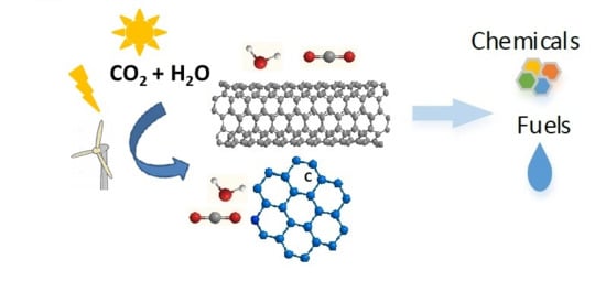
In the 1980s, carbon science was considered a mature discipline. This situation drastically changed in 1985 with the synthesis of the first molecule containing only carbon, buckminsterfullerene [1]. Later, Ijima’s work in 1991 triggered an enormous interest in other novel carbon architectures structurally related to fullerene, namely carbon nanofibers and nanotubes [2]. This interest spread to many fields of science, due to the high potential of these materials for use in many applications. One of these specific applications is in CO2 electrochemical reduction (CO2ER). This is a promising technology in research phase for large-scale carbon management applications, because it can convert captured CO2 into fuels or chemicals using renewable energy. CO2 utilization technologies have the potential to reduce annual greenhouse gas emissions by up to 3.5 Gt CO2-eq in 2030 [3]. Thus, they are able to contribute to climate change mitigation.
In order to be commercially deployed, CO2ER must exhibit high production rates (current densities), high selectivity (faradaic efficiencies for the desired products), high energy efficiencies (low overpotentials) and stable performances. It has been challenging to achieve these conditions simultaneously. Due to the stability of the CO2 molecule, its electro-reduction is a sluggish reaction, requiring high overpotentials and plagued with stability issues.
Carbon materials have been one of the materials of choice as constituents of electrodes for CO2 electro-reduction, and although depending on their fabrication process, they can be classified as sustainable materials. They have been used according to several strategies to improve CO2ER. This work reviews the latest developments of cathodes for CO2ER, with carbon black, mesoporous carbons, carbon nanofibers, graphene and its derivatives and/or carbon nanotubes as constituents. Methods of cathode assembly are also referred to. The strategies used in this fast-evolving field are discussed, having in mind a commercial application. Electrochemical performances of several materials, considering the findings of theoretical computational studies, are in some cases analyzed, when this type of study is available. Knowledge gaps and new promising R&D trends of nanocarbon-based materials development for this application are highlighted.
2. Carbon Black
Carbon black is produced by the incomplete combustion of petroleum heavy fractions. It is a form of para-crystalline carbon of high surface area. Although activated carbon has a more favorable surface area to volume ratio (>1000 m2/g) than carbon black, its low electrical conductivity makes it unsuitable as electrode material. Commercial carbon blacks, such as Vulcan or Ketjen black have been most frequently used as support to ensure large electrochemical reaction surfaces and to reduce noble metal loading.
2.1. Metal and Metal-Derived Particles Supported on Carbon Black
CO2ER can be carried out in gas phase, where gaseous CO2 is fed to the cathode through gas diffusion electrodes (GDE), or in liquid phase, where CO2 dissolved in the liquid electrolyte contacts the electrode. Figure 1 presents a schematic diagram of two possible configurations of both operation modes.
In the liquid phase cell, the availability of CO2 to react on the surface of the electrode is limited by the solubility of CO2 in the electrolyte. At room temperature and pressure the solubility of CO2 in water is only 33 mM [5]. To circumvent this problem, the use of GDEs was proposed [6]. In fact, one of the first uses of carbon materials in electrochemical reduction of CO2 was as support for metal-based catalysts in gas-phase CO2 electro-reduction [7]. Leveraging the knowledge acquired with GDEs in fuel cells [8], GDEs for electro-reduction of CO2 were implemented and investigated. These type of electrodes usually consist of Teflon bonded catalyst particles and carbon black forming a catalyst ink that is pressed or fabricated over the cathode substrate. This substrate can itself be a carbon material, as for instance glassy carbon, carbon paper, carbon cloth, or another type of electric conducting material, for instance a metallic mesh. The catalyst inks can be applied on the substrate using several methods, such as brushing, rolling, or dipping, forming the catalyst layer [7]. This layer together with a gas diffusion layer (porous material that can also be made of carbon) and with the membrane constitute the gas diffusion membrane electrode assembly (GDMA). Figure 2 shows a schematic representation of a gas-phase set-up indicating the localization of the GDE electrode and its components.
The following pioneer work was carried out employing GDEs with metal catalyst particles supported on carbon black, at ambient temperature and pressure. Mahmood et al. used Pb, In and Sn particles supported on Vulcan 72 [6]. CO2 was reduced to HCOOH on Pb GDEs in aqueous acidic electrolyte with faradaic efficiencies in excess of 80%. At an applied current density of 115 mA cm−2 (pH 2), the potential of the cathode rose from −2.7 V to −3.0 V vs. SCE. The equivalent ohmic drop (IR drop) corrected cathode potentials were −1.5 V rising to −1.8 V vs. SCE. In and Sn showed lower catalytic activity. When Ru-Pd alloy particles were employed as the catalyst, HCOOH was obtained at a current density of 80 mA of cm−2 and an applied potential of −1.1 V vs. SHE, in a 0.5 M KHCO3 electrolyte [10]. Cook et al. carried out electrolysis with copper particles supported on carbon black, in KOH electrolyte solution with the current yield of 53% for C2H4 formation at −4.75 V vs. Ag/AgCl (including IR drop) and obtained a current density of 667 mA cm−2 [11]. Ikeda et al. obtained a current density of 300 mA cm−2 at −1.25 V vs. SHE. Ethylene and ethanol were the main products detected [7].
In an interesting work, gas-diffusion electrodes of various metal catalysts supported on carbon black (Cr, Mo, Mn, Ru, Co, Rh, Ir, Ni, Pd, Pt, Cu, Ag, Au, Zn, Cd, In, Ti, Sn, and Pb) were used to reduce CO2 and nitrite ions dissolved in the electrolyte simultaneously [12]. The aqueous electrolyte consisted of 0.2 M KHCO3 and 0.02 M KNO2.
Urea was one of the reaction products. It resulted from the reaction of the ammonia-like precursor formed from the reduction of nitrite ions, and the CO-like precursor formed from CO2 electro-reduction in the presence of metal catalysts from the groups 11–14.
Near the turn of the century, the first works investigating CO2 electro-reduction at high pressure on GDE electrodes were undertaken [13,14]. A GDE loaded with Pt catalyst supported on carbon black reduced CO2 into methane at 20 bar with a faradaic efficiency of 38.8% with a very high partial current density of 600 mA cm−2 at an applied potential corrected for the IR drop of −1.93 V vs. Ag/AgCl. The electrolyte used was 0.5 M KHCO3. Ethylene, ethanol, ethane, carbon monoxide and formic acid were also produced [15]. Despite pressure being a very significant process intensification parameter, the studies of the influence of pressure stopped from the late nineties of the last century [4] until 2004 with one paper published [16]. These studies were only resumed in 2012 with the work of Dufeck et al. [17]. Despite the impressive increase in current density achieved by the several GDE cathodes and the variety of different catalysts investigated supported on carbon black, all these works have in common the very high overpotential necessary to carry out CO2 reduction both at atmospheric and at high pressure. Consequently, these processes present low energy efficiencies, with the exception of the aforementioned work of Dufeck et al., who achieved a significant increase in energy efficiency of the process (50%).
Further studies were conducted, in which catalyst particles with controlled particle size were dispersed onto carbon black. In particular, recent advances in the synthesis of nanoparticles (NP) allowed the examination of the potential for increasing reaction kinetics, due to the possibility of controlling surface area and surface morphologies. The effect of controlling the surface area by the use of nanoparticles, without the additional effect of dispersing the nanoparticles on a high surface area support, such as carbon black, is clearly illustrated by the work of Manthiram et al. [18]. In this work, Cu NP loaded on glassy carbon presented a faradaic efficiency up to ca. 80% for CH4 generation, with four times higher energy efficiency than the one obtained with a Cu foil cathode.
It is current knowledge that nanoparticle size and shape influence CO2 electro-reduction. For example, Zhu et al. [19] showed that an ink containing 8 nm Au NP monodispersed on Ketjen black and painted directly onto the carbon paper support presented the maximum faradaic efficiency for CO up to 90% at −0.67 V vs. RHE with a mass activity of 3A g−1 in 0.5 M KHCO3 electrolyte. When 500 nm long Au nanowires were used, at an applied potential of −0.35 V vs. RHE, the reduction faradaic efficiency (FE) reached 94% with a current density of 8.16 mA cm−2 (mass activity 1.84 A g−1 Au) [20].
Cathodes based on Au25 clusters dispersed on Vulcan XC-72R carbon black catalyst ink deposited on glassy carbon promoted the CO2 to CO reaction exhibiting an approximate 200–300 mV improvement over larger Au nanoparticles and bulk Au. Peak CO2 conversion occurred at −1 V vs. RHE with approximately 100% efficiency and a rate 7–700 times higher than that for larger Au catalysts. Productivities for CO formation of 1.26 mmol cm−2 h−1 were obtained in 0.1 M KHCO3 electrolyte [21]. The reversible Au25−CO2 interaction was explained by density functional theory (DFT) using a CO2-induced redistribution of charge within the cluster. Triangular Ag nanoplates were shown to reduce CO2 to CO with an FE of 96.8% in 0.5 M KHCO3 at −0.86 V vs. RHE, demonstrating that the edge site of Ag is the site responsible for CO selectivity [22].
Anchoring metal nanoparticles on carbon surface is another strategy to minimize agglomeration and for enhancing interfacial contact, promoting catalytic activity. Kim et al. [23] anchored Ag nanoparticles on carbon black with cysteamine and observed a decrease of the overpotential by 300 mV at 1 mA cm−2, and four-fold enhanced CO faradaic efficiency at −0.75 V vs. RHE with the optimal particle size of 5 nm compared to polycrystalline Ag foil.
A further strategy consists of regulating NP catalyst selectivity for CO2ER via the preparation of tunable core/shell structures. Li et al. [24] prepared Ketjen black inks containing SnO2 coated over Cu nanoparticles. They found out that reduction becomes Sn-thickness dependent. The thicker (1.8 nm) shell showed Sn-like activity to generate formate while the thinner (0.8 nm) shell was selective to the formation of CO. A current density of 4.6 mA cm−2, faradaic efficiency of 93% were reported at −0.7 V vs. RHE in liquid phase electrolysis employing 0.5 M KHCO3 as electrolyte.
Polycrystalline Pd is recognized as a poor CO2 reduction catalyst. It yields CO as major product. Current densities of 5 mA cm−2 with 10–30% Faraday efficiency (FE) for CO and 0–3% FE for HCO2− at −0.8 to −1.0 V vs. RHE in aqueous bicarbonate solutions were obtained [25,26,27,28]. Dispersing Pd nanoparticles of ca. 5 nm on carbon black Vulcan XC-72 support allowed the selectivity towards formate to be changed [29]. In liquid phase electrolysis high mass activities 50–80 mA per mg of Pd (current densities of 2.2 to 4.15 mA cm−2 with FE > 95% after 3 h) for HCO2− formation were obtained when driven by less than 200 mV of overpotential in aqueous bicarbonate solutions. The change in selectivity and increase in activity is attributed to a different reduction mechanism. On most materials the reduction proceeds via electron transfer to CO2, which requires a high overpotential. On Pd the rate-determining step was found to be the addition of electrochemically generated surface adsorbed hydrogen to CO2. Furthermore, as Pd/C has a high surface area to mass ratio, when compared to Pd foil, H adsorption is enhanced resulting in increased formate production.
The work of Del Castillo et al. [30] represents a step forward in the few studies of CO2ER to formate in continuous mode. A GDE was prepared by air-brushing an ink containing Sn NP supported on carbon black (Vulcan) onto the gas diffusion layer. This component consisted of a Vulcan microporous layer with a binder that was also brushed onto carbon paper. Gas-phase electrolyses were carried out. The catholyte was a 0.45 mol L−1 KHCO3 + 0.5 mol L−1 KCl aqueous solution and the anolyte was a 1 mol L−1 KOH aqueous solution with an anolyte flow per electrode area (Q/A ratio) of 0.57 mL min_1 cm−2. Pure gaseous CO2 was fed to the cell at a flow of 200 mL min−1. The catholyte and the anolyte only passed once through the cell. At a current density of 150 mA cm−2 it was possible to achieve a formate concentration of 2.5 g L−1 with a FE of 70%. At the expense of lowering FE, at current density of 200 mA cm−2, cell voltage of ca. −4 V and employing a lower flow rate, it was possible to obtain formate concentrations up to 16 g L−1.
Recently, nickel nitride was reported as another promising metal-like catalyst for generating CO. This material acted as CO2 surface enrichment material. The catalysts consisted of nickel nitride supported on Vulcan carbon black yielded a current density of 23.3 mA cm−2, faradaic efficiency for CO of 92.5% at −0.90 V vs. RHE with a cell voltage of 2.8 V [31].
A further interesting strategy involved the incorporation in anionic membranes of the ability of imidazolium ionic liquids to catalyze CO2 reduction [32]. This was achieved by functionalizing a solid membrane with a styrene backbone with 1-methyl imidazole. Using an Ag GDE electrode without a porous carbon as constituent of the catalyst ink, sprayed onto a carbon gas diffusion layer and these novel membranes, it was possible to raise the current at 3 V cell voltage by a factor of 14 in gas-phase electrolyses. Current densities higher than 100 mA/cm2 at 3 V voltages with CO product selectivity over 98% were obtained. Further improved performance was obtained by incorporating an anion exchange ionomer and carbon black into the Ag cathode. Potentiometric electrolysis in gas phase at a fixed current of 200 mAcm−2 showed that 98% selectivity could be maintained at about 3 V voltage for five months, with a voltage increase of only 3 μV/hour. The improved performance was attributed to the extended three phase boundaries in Ag cathode [33]. These orders of magnitude of current densities are already meaningful for industrial deployment.
2.2. Molecular Catalysts
Another promising strategy that has been investigated is the integration of metal complexes with carbon materials, establishing the link between heterogeneous and homogeneous catalysis. These metal complexes are composed of metal centers with tunable oxidation states and macrocyclic organic ligands providing chemical stability and storage of reducing intermediates and/or protons.
Several organic-metallic compounds have been studied as molecular homogeneous catalysts for CO2ER. This type of work has been reviewed by Qiao et al. [34]. Thus, their catalytic activity and selectivity towards CO2ER is already known for many of them. However, when the goal is to get these molecules to work as CO2ER heterogeneous catalysts, linked to a support, this task is often very challenging. The difficulties are assuring the stability of the molecular catalysts after a high number of cycles and the need for a cost-effective method to separate the catalyst from the electrolyte.
Phthalocyanines and porphyrin metal complexes have been most studied for several decades but still present challenges in terms of productivities, energy efficiencies and stability.
GDEs of Co-, Mn-, Zn-, Cu phthalocyanines were examined as catalysts for CO2 electro-reduction. Co-Pc showed the best performance yielding near 100% selectivity for CO at 80 mA cm−2 and −4.39 V vs. Ag/AgCl applied potential in aqueous electrolyte consisting of solutions of H2SO4, phosphate or borate buffers with ionic strength of 3 ensured by Na2SO4 [35]. When electrolyses were conducted in dilute H2SO4 solutions (pH 2), current densities of 137 mA/cm2 and faradaic efficiencies for CO of 14% were obtained at −2.2 V vs. SCE applied potential. At an applied potential of −1.5 V vs. SCE current densities of 22 mAcm−2 and faradaic efficiencies for CO of 100% were observed [36].
The coupling of CO2ER with nitrite ions reduction was also investigated, where the metal catalysts were replaced by metallophthalocyanines (M-Pc) [37,38]. The formation of urea, CO, formic acid and ammonia at the gas-diffusion electrodes with group 8–14 catalysts, except for Al and Ge, was observed. The maximum current efficiency of urea formation was about 40% at −1.5 V vs. SHE on Ni–Pc catalysts. The ability for urea formation on various M–Pc catalysts depends on the current efficiencies of both CO and NH3 formation.
Recently, Wang et al. designed a Co phthalocyanine (CoPc2) bearing one trimethyl ammonium moiety and three tert-butyl groups appended on the phthalocyanine macrocycle [39]. Figure 3 shows the formula of this complex and presents current density, selectivity for CO production as a function of the potential and the bulk electrolysis curve at fixed potential (E = −0.72 V vs. RHE), illustrating the performance of one of the best catalytic systems using state-of-the-art molecular catalysts. The complex was dispersed into porous films of carbon black powder or multiwalled carbon nanotubes. Electrolysis in gas phase was carried out using carbon paper as the support for the catalyst ink. CO production occurred with selectivity of ca. 95% and good stability with a maximum partial current density of 165 mA cm−2 at −0.92 V vs. RHE (corrected for ohmic drop), in 1 M KOH electrolyte.
Among pioneer works, the influence of pressure in CO2ER using metal-porphyrin catalysts was also investigated [40]. GDEs made of carbon black were impregnated with metal-meso-tetraphenylporphyrin (TPP) catalysts. The catalysts Co- and Fe-TPP, which are relatively active in the electrochemical reduction of CO2 under atmospheric CO2, increased current efficiencies at 20 bar up to 97.4% and 84.6%, respectively. At Cu- and Zn-TPP supported GDEs that showed low activity under atmospheric CO2, the current efficiencies for CO2 reduction increased up to 50.5% and 65.8%, respectively, under 20 bar CO2. At these active metal-TPP supported GDEs, the potential of CO2 reduction shifted positively due to the increase in CO2 pressure. These results are another example of the influence of high pressure on the enhancement of the electrocatalytic activity of metal-TPPs for CO2 reduction. Current research trends are investigating electrodes containing porphyrin complexes and other carbon materials. They will be dealt with in Section 4, Section 5 and Section 6.
3. Mesoporous Carbon-Based Electrodes
One disadvantage of carbon black is its microporous structure. The metal particles may sink inside the micropores, decreasing the electro-catalytically effective surface area. This leads to the development of mesoporous carbons. These materials (2 nm < pore sizes < 50 nm) have attracted a lot of attention, due to their regular structure, high surface area, large pore volume and a narrow pore size distribution. They can find potential applications in several fields and their use in CO2ER was also investigated. While advantages of the use of these materials as catalyst supports in comparison with carbon black has been shown, for instance for the oxygen reduction reaction [41], in CO2ER several textural properties come into play, and these advantages may not become immediately apparent. Pore structure, existence of heteroatoms in carbon skeleton, hydrophilic or hydrophobic properties need to be first optimized for CO2ER. One example of these issues is given by Castelo-Quibén et al. [41]. They developed Ni-catalysts by impregnation of mesoporous carbon nanosphere supports and also by Ni doping during the synthesis of the supports. In the case of the catalysts prepared using the later method, catalytic activity was not enhanced by the presence of Ni phases. Ni was incorporated into the carbon matrix in such a way that the metal phase was not accessible to the electrolyte, so the dissolved CO2 could not reach the metal particle. Catalytic activity was enhanced when the catalysts were prepared by impregnation, as Ni particles were accessible to the electrolyte at the surface of the pores. All the catalysts developed were able to reduce CO2 to C1−C4 hydrocarbons, even supports, which did not have metal. The highest C1−C4 hydrocarbon production of 117 ppm was obtained for a Ni containing catalyst at −1.6 V vs. Ag/AgCl with faradaic efficiencies for hydrocarbons of 0.3% in liquid after a 200 min phase electrolysis in batch mode. This work shows that the presence of mesopores has a positive effect in both oxygen reduction reaction and CO2ER, as it also facilitates ion diffusion at a high speed [42]. Song et al. reported a nitrogen-doped ordered cylindrical mesoporous carbon as a metal-free catalyst for CO2ER into ethanol. Materials with different configurations were prepared (cylindrical pore structure c-NC and with inverse pore structure i-NC) [43]. The c-NP configuration showed superior selectivity for ethanol. The catalyst ink was brushed onto a porous layer previously painted onto carbon paper. Electrolyses in gas-phase were carried out using 0.1 M KHCO3 as electrolyte yielded faradaic efficiency of 77% for ethanol at −0.56 V vs. RHE with current densities of ca. 0.25 mA cm−2. These results were attributed to the synergetic effect of the nitrogen heteroatoms and the cylindrical channel configurations, which facilitates the dimerization of key CO* intermediates and subsequent proton-electron transfers. Figure 4 presents a schematic illustration of c-NC and i-NC for CO2 electroreduction.
Mesoporous N-doped carbon derived by sacrificing metalorganic frameworks (MOF), are also receiving attention. Kuang et al. prepared an N-doped mesoporous carbon from the pyrolysis of Zn-based zeolitic imidazolate framework-8 (ZIF-8) [44]. Electrolysis in liquid phase with 0.1 M KHCO3 as electrolyte yielded a faradaic efficiency of ~92% for CO and a partial current density for CO of −6.8 mA·cm−2, achieved at a potential of −0.58 V vs. RHE. It was concluded that the hierarchical porosity, with large specific surface area and pore volume, can improve the three-phase contact and transport of reactants and products, which can be beneficial for the electro-catalytic CO2 reduction in the aqueous phase. The synthesis of this type of carbon material, involving the assembly of relative elaborated architectures by using commercial reagents and subsequently sacrificing them through annealing, is expensive and time consuming. It will hardly be cost effective for a commercial application.
4. Carbon Fibers
Macroscopic carbon fibers attached to each other in a form of a matt—carbon cloth (CC)—have low electrical resistance, relatively low cost, and large surface area. This material is widely used for the preparation of electrodes for low temperature fuel cells and was investigated as catalyst support for CO2ER.
Morlanés et al. prepared electrodes consisting of perfluorinated cobalt phthalocyanine (CoFPc) immobilized on CC [45]. As this complex also catalyzes O2 evolution, a two-electrode system was assembled with the same electrodes as cathode and anode, and 0.5 M NaHCO3 electrolyte in both cathodic and anodic compartment, for liquid phase electrolysis. Current densities in the range of 1−6 mA cm−2, with faradaic efficiencies of CO ~90% at an applied cell voltage range of ca. 2–3 V were achieved. Production rates in the range of 24–95 μmol cm−2 h−1 were observed.
The organometallic complex (fac-Mn(apbpy)(CO)3Br) (apbpy = 4-(4-aminophenyl)-2,20-bipyridine) grafted electrochemically onto CC, was examined as catalyst for CO2ER [46]. The catalyst was covalently bonded to CC. A faradaic efficiency of around 60% for CO and 40% for H2 at −1.35 V vs. Ag/AgCl is achieved together with a partial current for CO of ca. 0.9 mAcm−2 in electrolysis carried out in liquid phase with 0.1 M KHCO3 electrolyte. However, it was shown that even if these materials are made of long fibers, carbon cloths do not possess good electrode properties, due to the existence of double porosity and electrical conduction problems. Thus, the use of such a material as an electrode is not recommended [47].
Carbon nanofibers were also investigated as constituents of cathodes for CO2ER. The materials are made of graphene layers, have good electrical conductivity, high surface areas and represent a good compromise between structural and textural properties (low content in micropores and impurities). These nanofibers can be obtained by the decomposition of carbon-containing gases, like methane or carbon monoxide, over small metallic particles as catalysts, typically metals of the iron subgroup. Alternatively, they can be easily synthetized from spinnable polymer precursors, such as polyacrylonitrile [48]. Through this process, fibers of higher purity and without traces of metals that can influence catalysis can be obtained.
Magdesieva et al. investigated several porphyrin and phthalocyanine transition metal complexes supported on activated carbon fibers (surface area 1400–1500 m2 g−1) and on activated carbon (surface area 2000 m2 g−1) [49]. GDEs were prepared by pressing a paste containing the supported metal complexes with the gas diffusion layer. The partial current densities for CO production, measured in 0.5 M KHCO3 solutions, were up to 70 mA cm−2 at −1.5 V vs. SCE. The catalysts supported on activated carbon fibers showed better performance in CO2ER than those supported on activated carbon for smaller complex sizes that could be adsorbed on the surface of the nanopores of the activated carbon fibers. On the contrary, for larger complexes the catalysts supported on activated carbon showed better performance, due to the wider pores (microporosity) available in this material.
Kumar et al., using N-doped carbon nanofibers (CNFs) directly as electrode, reduced CO2 into CO in liquid phase at −0.573 V vs. RHE with 98% faradaic efficiency and current densities near 0.5 mAcm−2 [50]. An aqueous solution of the ionic liquid 1-buthyl-3-metyl-imidazolium tetrafluoroborate was used as electrolyte. The activity of a nitrogen-free catalyst (graphite) under similar experimental conditions showed negligible activity for CO2ER. This electrolyte was chosen due to the high CO2 absorption capacity of some ionic liquids [51]. The N-doped CNFs were synthesized by pyrolysis of electrospun nanofiber mats of heteroatomic polyacrylonitrile (PAN) polymer.
Yang et al. prepared N-doped carbon fibers with a core of Ag nanowires of 70–80 nm diameter [52]. The objective was to increase the local concentration of CO2 around the Ag nanowires (AgNWs), due to its porous structure. AgNWs were well dispersed in Tris buffer (pH = 8.5), which was followed by adding a specific amount of dopamine (DA) to form the polydopamine (PDA) shell under continuous stirring. Subsequently, the material was carbonized under argon atmosphere at different temperatures. The PDA decomposed, creating the N-doped carbon layer. Figure 5 shows schematically the preparation process of these catalysts. A synergistic effect was observed between the Ag nanowires and the N-doped carbon shell. The working electrodes were prepared by drop-casting the catalyst ink containing the wrapped Ag nanowires on carbon paper. Electrolysis in liquid phase with 0.1 M KHCO3 electrolyte showed that CO and H2 were the major products formed and no liquid products were detected. The higher faradaic efficiency of 96% was obtained at −0.8 V vs. RHE with CO formation rates of 774 μmol m−2 s−1. The CO formed was further reacted with organic compounds to form organic carbonyls.
5. Graphene
Graphene (GN) can be prepared using chemical-, electrochemical- or mechanical-exfoliation of graphite. This constitutes the so-called bottom down approach. In the bottom up approach chemical synthesis or chemical vapor deposition is employed. This nanomaterial has a two-dimensional honeycomb lattice of sp2 hybridized carbon atom. It can be grown in different morphologies including monolayer and multilayer graphene nanosheets, zero-dimensional graphene quantum dots, graphene nanoflowers and graphene nanoribbons. Since its first laboratory synthesis in 2004, it has been a hot topic of research, due to its remarkable huge surface area, high electrical conductivity, high thermal conductivity, good chemical and mechanical properties [53]. Among other end uses, these characteristics make graphene very interesting for catalytic applications, and thus, it has also been investigated as electrode component in electro-reduction of CO2. As in the case of carbon black, graphene and its modifications were utilized having different strategies in mind. Interestingly, synergies between metal catalysts and these carbon materials were disclosed. An example of metal-support synergy was reported by Rogers et al. [54]. These authors revealed that the structural and electronic properties of the graphene nanoribbon (GNR) matrix increased the electrochemically active surface area of Au nanoparticles assembled on this matrix. This material showed better activity for CO production (36.8 A g−1), stability and lower overpotentials than Au nanoparticles supported on carbon black (6.4 A g−1). Faradaic efficiencies for CO were >70%.
Geioushy et al. also found a synergy between Cu2O and graphene, when GN was used as the support of the nanoparticles [55]. An electrode consisting of an ink containing the composite of GN/Cu2O with an average particle size of 20–50 nm, coated on copper foil, was more active than the electrode without graphene. A current density of approximately 12.2 mAcm−2 at −1.7 V vs. Ag/AgCl was obtained using linear sweep voltammetry, which was higher than for a Cu2O electrode (8.4 mAcm−2). Electrolysis in liquid phase with 0.5 M KHCO3, as electrolyte yielded ethanol (~0.34 ppm) as predominant product at −0.9 V vs. Ag/AgCl with a faradaic efficiency up to 9.93%. No ethanol was detected when the electrode containing only Cu2O was used.
Pristine graphene is not active for CO2ER, but, by introducing atomic defects through heteroatom doping, it can be made active for this reaction [56]. Wang et al. described an electrode with a catalyst ink including N-doped graphene (NG) brushed on to carbon paper, as metal free catalyst [57]. These authors reported a steady current density at around −7.5 mA cm−2 throughout the 12 h electrolysis in liquid phase carried out at an applied potential of −0.84 V vs. RHE with faradaic efficiencies for formate varying in the range of 70–63% in 0.5 KHCO3.
Wu et al. used N-doped 3D-graphene (NG) foam as a metal-free catalyst to reduce CO2 to CO in gas phase [58]. The ink containing N-doped graphene foam was sprayed onto the gas diffusion layer. A current of ca. 1.8 mAcm−2 (FE for CO ca. 70% and FE for HCOOH of 3.0%) was obtained at an applied potential −0.58 V vs. RHE in 0.1 M KHCO3. DFT calculations confirmed the pyridinic N as the most active site for CO2 reduction in accordance with experimental results.
Boron doping is much less investigated than nitrogen doping. Sreekanth et al. prepared electrodes of B-doped graphene ink drop-casted on glassy carbon and reported a faradaic efficiency of CO2 reduction to formate of 66% in liquid phase, at −1.4 V vs. SCE with a current density of ca. 0.5 mAcm−2 [56].
N-doped graphene has also attracted a lot of attention as an electrode support displaying metal-support synergies that increase catalytic activity, as described below. Li et al. reported that N-doped graphene could reduce CO2 to formate with a mass activity of 7.7 A g−1 and maximum faradaic efficiency of 65% at −0.9 V vs. RHE in electrolysis carried out in 0.5 KHCO3 electrolyte, with hydrogen as the other electrolysis product [59]. Furthermore, it was reported that electrolysis carried out with 7 nm Cu nanoparticles dispersed on N-doped graphene yielded hydrogen, formate, methane, ethylene and ethane, but no CO. Ethylene was predominantly formed and formate production suppressed at −0.9 V vs. RHE with a faradaic efficiency of 19% and a mass activity for ethylene of 2.9 A g−1Cu. The mass activity for ethylene of Cu nanoparticles dispersed on Ketjen carbon black prepared for comparison was ca. 0.5 A g−1Cu.
Recently Han et al. prepared graphene with a large number of topological defects using a nitrogen removal method [60]. This material presented numerous catalytically active sites, high electronic conductivity and strong adsorption of CO2. A cathode was prepared by loading an ink containing the defected graphene on carbon paper. Electrolysis carried out in liquid phase using 0.1 M KHCO3 as electrolyte was undertaken. Faradaic efficiency of ~84% and a partial current density for CO of 1.3 mA cm−2 at −0.6 V vs. RHE were reported. This current was higher than the one obtained with pristine graphene, nitrogen-doped graphene and edge-rich graphene electrodes.
Importantly, Chai et al. predicted using both density functional theory (DFT) and ab initio molecular dynamic calculations that the interplay of N-doping and curvature can effectively tune the activity and selectivity of graphene/carbon-nanotube (CNT) catalysts [61]. The graphene catalyst without curvature showed strong selectivity for CO/HCOOH production, whereas the CNT with a high degree of curvature was effective for both CH3OH and HCHO production. Curvature was also very influential to tune the overpotential for CO formation.
6. Graphene Derivatives
Graphene oxide (GO) is one important graphene derivative. It contains several functional groups, such as epoxy, hydroxyl, carbonyl and carboxyl groups. GO has weak electrical conductivity, due to the presence of hydrophilic functional groups. One way to increase its electrical conductivity is by removing oxygen containing functional groups to produce reduced graphene (rGO).
One approach to achieve high mass activities of catalysts is to decrease particle size. This approach was also investigated for graphene derivatives-based electrodes. It was observed that decreasing particle size below a certain limit favors H2 evolution, due to abundant low coordinated sites of the very small nanoparticles [62,63]. This results in poor selectivity towards CO2 reduction products. Zhao et al. circumvented this problem by supporting ultra small (ca. 2.4 nm) Au NPs on rGO sheets [64]. They obtained Au-specific mass activities (>100 A g−1) and good faradaic efficiencies (32–60%) for the CO2 to CO conversion at moderate overpotentials (450–600 mV). Furthermore, the Au NPs were modified with amines with the capability of CO2 adsorption and suppressing H2 evolution. This modification allowed faradaic efficiencies to be increased to 59–75%. An amine structure dependent effect in selectivity was revealed. Among all the modifiers, oleylamine exhibited the highest CO selectivity with CO partial current densities of ca. 6 mAcm−2 at −0.7 V vs. RHE. The catalyst was prepared by dropping the catalyst ink containing the rGO composite on a layer of Vulcan carbon black painted on a surface of carbon paper. CO2 reduction was carried out in liquid phase, in 0.1 M KHCO3.
Cu nanowires of 20 nm width were selective for CH4 (FE of 55%, partial current densities near 8 mA cm−2) at −1.25 V versus RHE in 0.1 M KHCO3; however, selectivity was sensitive to morphological changes. Wrapping the nanowires with rGO stabilized the catalyst preserving morphology and selectivity [65]. Electrodes were prepared by loading the wrapped Cu nanowires in rGO in Ketjen carbon black, and then, the ink solution was spread onto carbon plates.
A further study of metal particles supported on rGO was presented by Hossein et al. [66]. These authors prepared a catalyst in which adenine was bonded on the surface of rGO via diazonium reaction. Adenine-rGO was drop-casted on a glassy carbon substrate. Then, Pt was deposited on the surface of adenine-rGO to prepare the Pt@Adenine-rGO working electrode. In acidic media, nitrogen-containing heterocyclic on the structure of adenine was protonated and allowed the formation of hydrogen atoms on the surface of Pt, which, interacting with carbon dioxide, reduced CO2 to methanol. This alcohol was obtained as the main product with a faradaic efficiency up to 85% and a current density of 0.5 mA cm−2. The electrolyte used was 0.1 M KNO3.
Ning et al. prepared a composite of cuprous oxide (Cu2O) nanocubes on nitrogen-doped reduced graphene oxide (NrGO) to fabricate a Cu2O/NrGO composite [67]. An ink of this composite was prepared, smeared and let dry on a glassy substrate to produce the working electrode. Electrolysis in 0.1 M KHCO3 exhibited a faradaic efficiency of ethylene (19.7%) at −1.4 V vs. RHE with stable current density of 12 mAcm−2. The mass activity of Cu2O supported on reduced graphene oxide towards C2H4 formation reaches as high as 136.1 mmol h−1 g−1, which was more than 24-fold of pristine Cu2O. The pyridinic N in reduced graphene oxide was supposed to behave synergistically with Cu2O, leading to an enhancement of activity and durability of Cu2O for electrocatalytic CO2 reduction to ethylene. Figure 6 shows SEM images of reduced graphene oxide (rGO) the Cu2O/NrGO composite catalyst and its constituents.
Attaching molecular catalysts to graphene derivatives was also investigated. Zhou et al. prepared a re-functionalized porphyrin on graphene oxide that was then deposited onto a glassy carbon electrode (GC) for CO2ER into syngas [68]. The complexes fac-M(4-amino-bipy)(CO)3X (M = Mn and X = Br or M = Re and X = Cl, bipy = 2,2′-bipyridine) were synthetized and immobilized on GrO via diazonium grafting. The prepared electrode catalyzed CO2 to CO conversion with an optimized turnover frequency of up to 4.44 s−1 for CO generation. The electrolyte used was aqueous acetonitrile. Mass transfer limitations affected activity. Stirring the electrolyte solution produced a threefold increase of the reaction rate. Co-generation of H2 using the bare glassy carbon electrode enabled the production of syngas with tunable CO/H2 ratios, by changing the CO2 diffusion rate, or by deliberately adjusting the surface coverage of the catalyst at the electrode.
Choi et al. prepared a porphyrin/graphene framework (FePGF) composed of Fe(III) tetraphenyltrimethylammonium porphyrin and reduced liquid crystalline graphene oxide [69]. A high surface area carbon fiber paper was used as a substrate for FePGF catalyst. A current density was reported of 1.68 mA cm−2 with 98.7% CO faradaic efficiency at an overpotential of 430 mV for 10 h with a cathodic energy efficiency of 60.9%, corresponding to a turnover frequency of 2.9 s−1 and 104 400 turnover number. These authors also examined the effect of the degree of GO reduction. The catalyst FePGF appeared to offer the required balance between electrostatic interaction and reduced character, yielding both high catalytic efficiency and long-term stability.
Yuan et al. investigated functionalized GO as metal-free catalyst. Pyridine derivatives, such as 4-hydroxypyridine, 4-aminopyridine, 8-hydroxyquionline, 5-amino-1,10-phenanthroline and pyridoxine (vitamin B6), were grafted on GO sheets [70]. An ink containing the catalyst was prepared and spread over carbon paper for cathode assembly. The GO-VB6 catalysts demonstrated superior activity for the electrochemical reduction of CO2 to ethanol than the modifications with the other four pyridine derivatives on GO sheets. The catalytic active of GO-VB6 was affected by the pyridinic N contents in the GO-VB6 catalysts. The experimental data revealed that pyridinic N is the active site for CO2ER. Besides, the catalytic activities of pyridine derivative modified GO exhibit distinct performances, which are not only closely related to the pyridinic N contents of the GO-X, but also the structure of grafted pyridine derivatives. Electrolysis in liquid phase was carried out in 0.1 M KHCO3 electrolyte. The best results were observed for GO-VB6 with an N content of around 2.32% on the surface of GO sheets, which produce the maximum FE of ethanol of approximately 37%, with a partial current density of ca. 0.25 mA cm−2 at −0.4 V vs. RHE.
Three dimensional electrodes have been proposed to overcome the low CO2, electrolyte accessibility to catalytic sites and mass transfer limitations. rGO hydrogels have been suggested, among others, for electrochemical applications, due to their good electrical conductivity, suitable mechanical properties and thermal stability [71]. The highly porous structures of hydrogels containing large amounts of water favor electrolyte accessibility and wettability in aqueous media. Choi et al. have developed an iron porphyrin-based rGO hydrogel, prepared via a hydrothermal method, as a three-dimensional catalyst for CO2ER [72]. This catalyst was deposited into a reticulated vitreous carbon electrode. At −0.39 V vs. RHE, CO2 was reduced to CO with ca. 96% faradaic efficiency and a stable current density of 0.42 mAcm−2 in a 20 h electrolysis, carried out in 0.1 M KHCO3.
7. Carbon Nanotubes
Carbon nanotubes are long, thin graphitic cylinders, which, if simplified, can be regarded as a sheet of graphite rolled into a cylinder. They can have a single cylindrical wall (SWNTs) or multiple walls (MWCNTs), with cylinders inside the other cylinders. Electrodes composed of carbon nanotubes have generated much interest because of their high conductivity, large surface area and their ability to facilitate catalytic processes. These materials have also been investigated for CO2ER following different strategies.
Supporting metal nanoparticles on CNT was one of the strategies followed to increase catalyst performance. Feng et al. showed that surface-area-normalized activity for CO2 reduction is linearly correlated with grain boundary (GB) surface density on Au/CNT (Figure 7) [73]. They proposed grain boundary engineering as a strategy to improve the catalytic activity of metal nanoparticles. This correlation led to an understanding of the different current densities and faradaic efficiencies reported for Au nanoparticles of different size and shape [19,20,21]. Au/CNT electrodes were prepared by depositing Au nanoparticles on a CNT film using electron beam evaporation. The Au/CNT films were rolled into yarns and connected to Au wires. Electrolyses in liquid phase were carried out in 0.5 M, and NaHCO3, CO and H2 were the major products formed with current densities in the order of magnitude of µAcm−2.
Recently, a catalyst was prepared consisting of Au nanoparticles supported on poly(2,2′-(2,6-pyridine)-5,5′-bibenzimidazole) polymer (PyPBI) wrapped multiwall carbon nanotubes as the cathode catalyst [74]. The catalyst ink containing the prepared catalyst multiwall carbon nanotubes/PyPBI/Au was airbrushed on the gas diffusion layer. Figure 8 shows a schematic representation of the catalyst and of the microfluidic electrolysis cell used. This catalyst was further improved, and high jCO (~99, 158 mA cm−2) was obtained at low overpotential (~0.70, 0.94 V) and high CO energetic efficiency (~63.8, 49.4%), respectively [75]. The performance was stable for at least 8 h. The observed high activity was due to a high electrochemically active surface area, in combination with the low loading of the highly-dispersed Au nanoparticles.
Zhao et al. compared differently prepared catalysts of tin oxide particles supported on multiwall carbon nanotubes [76]. The cathode was prepared by pressing the catalytic ink, also containing carbon black, onto a stainless steel mesh. Liquid phase electrolysis carried out in 0.1 M KHCO3 yielded maximum faradaic efficiencies of 60% with 25% energy efficiency for HCOOH formation and current densities in the range of 5–10 mAcm−2. Different morphologies of the particle agglomerates made little difference in the electrocatalytic selectivity and activity.
Results that stand out among the studies of metal nanoparticles supported on carbon nanotube catalysts are presented in the work of Ma et al. [77]. The authors investigated MWCNTs containing Ag nanoparticles in an optimized flow system. The electrode was prepared by air brushing the ink containing MWCNT and Ag nanoparticles onto the gas diffusion layer. Electrolysis in gas-phase yielded faradaic efficiencies of CO of 95%, a current density of 350 mA cm−2 and energy efficiency of 45%. An electrochemical impedance spectroscopy study revealed that this mixed catalyst had lower resistance to charge transfer/higher charge transfer rate, which enhanced the electrochemical reaction.
Bashir et al. studied the effect of metal loading of tin oxide supported on acid functionalized multiwall carbon nanotubes (SnO2/MWCNT) [78]. The cathode was prepared by adding the catalyst ink layer by layer onto carbon paper. Liquid phase electrolysis was carried out in 0.5 M NaHCO3. The best result was obtained for an electrode with 20% weight of SnO2. Formate faradaic efficiency of 27.2% was achieved with a current density of 80 mAcm−2 at a potential of −1.7 V vs. SCE.
Marepally et al. prepared catalysts consisting of Cu nanoparticles deposited onto commercial carbon nanotubes, preliminarily activated with HNO3 to create oxygen functional groups on their external surface (o-CNTs) [79]. These catalysts were shown to be active in C−C coupling. The catalyst was deposited on a gas diffusion layer and electrolysis was carried out in gas phase using 0.5 M KHCO3 as electrolyte, applying a constant bias of −2V. Results showed that Cu NPs supported over CNTs greatly depend on the method of preparation. The catalysts prepared using the method developed by these authors (CuCNT) gave better performances than the electrodes prepared via conventional impregnation methods (CuCNT-Imp). The higher production of methanol for CuCNT with respect to CuCNT-Imp (0.98 vs. 0.31 μmol h−1) was ascribed in part to the higher surface area of Cu NP, as the prepared CuCNT showed smaller particles, but also to the state of oxidation of Cu (Cu0 in CuCNT). The reduction of CuII to Cu0 in CuCNT-Imp during electrolysis likely involves only the shell of the particles, with formation of a core-shell structure (Cu0 in the external surface and CuII in the core of the particle) that influences the electronic properties of the surface and consequently the reactivity. Moreover, C2-C3 products, ethanol, acetic acid, isopropanol, and acetone, were obtained with the developed catalysts, showing the possibility of C−C bond formation.
Molecular catalysts were also investigated in combination with carbon nanotubes. Walsh et al. prepared an electrode consisting of a complex fac-Mn(apbpy)(CO)3Br, apbpy = 4-(4-aminophenyl)-2,2′-bipyridine cast on a Nafion membrane on a glassy carbon substrate [80]. When MWCNT was also cast on the membrane (MWCNT/Nafion/[Mn(bpy)(CO)3Br]), a 10-fold enhancement in current density in cyclic voltammetry measurements was observed under CO2 at −1.4 V vs. Ag/AgCl at pH 7 (3 mA cm2 vs. 0.3mA cm2) using phosphate buffer pH 7 as electrolyte. This enhancement was caused by the increase in the electroactive concentration of the complex, due to the large area of the MWCNT support. Further progress was reported with the complex [Mn(bpy(tBu)2)(CO)3Br] (2, where (bpy(tBu)2) = 4,40-di-tert-butyl-2,20-bipyridine). At neutral pH, a current density of 2.65 mA cm−2 at −1.5 V vs. SCE, a selectivity towards CO2 (CO: H2 = 0.33) and a faradaic efficiency for CO of 24% were achieved [81].
Aoi et al. investigated CO2ER using a glassy carbon electrode modified with a cobalt(II) chlorin complex, adsorbed on multiwall carbon nanotubes, in liquid phase electrolysis at an applied potential of −1.1 V vs. NHE to yield CO with a faradaic efficiency of 89%, with hydrogen production accounting for the remaining 11% in aqueous Na2SO4 at pH 4.6 [82]. After 30 h of electrolysis, 0.4 mmol cm−2 of CO were produced. When MWCNTs were replaced by rGO, which is planar, as a support material of CoII(Ch), the CO and H2 yields became much smaller. They concluded that the three-dimensional assembly of MWCNTs with CoII(Ch) on the electrode surface may play an important role for the selective electrocatalytic reduction of CO2 to CO.
Cobalt meso-tetraphenylporphyrin (CoTPP) was directly immobilized onto CNT via adsorption [83]. The working electrode was prepared by drop-casting the suspension containing CoTPP and CNT on the glassy carbon electrode. Four hours of electrolysis in liquid phase with 0.5 M KHCO3 as electrolyte at −1.35 V vs. SCE accumulated 189 µmolcm−2 of CO.
Zhang et al. introduced cyano groups in the cobalt phthalocyanine molecule (CoPc-CN). These molecules were uniformly anchored on carbon nanotubes [84]. The working electrodes were prepared by drop-drying the catalyst inks onto carbon fiber paper. Electrolysis in liquid phase using as electrolyte 0.1 M KHCO3 near neutrality yielded a current density of 15.0 mA cm−2 and faradaic efficiency for CO >95% at −0.63 V vs. RHE (overpotential of 0.52 V, IR corrected).
In order to increase the structural stability of molecular catalysts immobilized on CNTs, Han et al. prepared a hybrid catalyst material consisting of a CNT core and cobalt polyphthalocyanine (CoPPc) sheath [85]. The catalyst powder was blended with Ketjen black carbon and Nafion polymer binder and drop-cast onto carbon fiber paper (CFP) as the working electrode. Extensive cross-linking of CoPPc on the conductive support not only suppresses the aggregation of organic molecules and enlarges their electrochemically active surface area but also contributes to their physical and chemical robustness. Electrolysis in liquid phase conducted in 0.5 M KHCO3 electrolyte yielded at least 24 h stable current density of 18.7 mAcm−2 and faradaic efficiencies for CO >80% at −0.5 V vs. RHE (0.43 V overpotential).
Wang et al. prepared a catalyst ink containing the Co complex of the planar tetradentate ligand 2,2′:6′,2″:6″,2′″-quaterpyridine [Co(qpy)]2+ and the MWCNT [86]. The ink was drop-casted on carbon paper. Electrolysis in liquid phase using this cathode in 0.5 m NaHCO3 (pH 7.3) yielded CO with 100% faradaic efficiency with a current density of 9.3 mA cm−2 that could be sustained for several hours at −0.48 V vs. RHE (340 mV overpotential).
Wang et al. prepared porous carbon membranes that were used directly as electrodes. These membranes consisted of multiwalled carbon nanotubes embedded in an N-doped carbon membrane matrix [87]. In these membranes the macropores provide mass transport highways while the mesopores and micropores provide a large surface area and high population of spatially accessible electroactive sites for CO2ER. The nitrogen species incorporated into the carbon framework constitute the active sites for the reaction. The faradaic efficiency for the production of formate was 81% at −0.8 V vs. RHE, the remaining products were CO and H2. Electrochemical stability of at least 36 h and current densities of ca. 6 mAcm−2 were obtained in potential controlled electrolysis in 0.1 M KHCO3.
8. Nitrogen-Doped Carbon Nanotubes
Heteroatom doping, in particular N-doping of carbon nanotubes (N-CNT), was also an approach used for developing N-CNT-based catalysts. Zhang et al. drop-casted multiwall CNT on a glassy carbon electrode [88]. The CNT was doped with nitrogen and oxygen. Oxygen doped CNT and CNT electrodes mainly gave H2 as the product (>90%) with a small amount of CO (<1%). A polyethyleneimine (PEI) overlayer that is used as CO2 absorbent was applied to N-CNT/GC by attachment to the surface of CNT based on van der Waals forces. PEI-N-CNT exhibited the most positive onset potential for CO2 reduction. Electrolysis in 0.1 M KHCO3 at −1.8 V vs. SCE for 24 h exhibited a steady-state catalytic current density of 7.2 mAcm−2. Formate was the dominant product formed with a faradaic efficiency of 85%.
Wu et al. showed that N-doped CNTs were active for CO2ER into CO at a significantly lower overpotential than pristine CNTs. GDEs electrodes were prepared by spraying an ink containing N-doped multiwall carbon nanotubes with a bamboo shape on a gas diffusion layer [89]. The bamboo-like structure is a characteristic feature of nitrogen atom defects in CNTs, which originates from the formation of a positive curvature surface during substitution of nitrogen atoms into the graphitic structure [90]. The long-term performance of N-doped CNT catalysts at constant applied potential of −0.8 V vs. RHE for 10 h was tested. A stable current density at around −1.0 mA cm−2 was obtained. FE of CO fluctuated slightly around 80%.
Sharma et al. synthesized N-doped CNTs with various surface structures and nitrogen contents by choosing different precursors and controlling the growth temperature [91]. Electrodes were prepared by spraying the catalyst ink over a carbon gas diffusion layer. The catalytic activity of these N-doped CNTs was found to depend upon the nature of nitrogen defects and defect density. The presence of graphitic and pyridinic N defects significantly decreased the absolute overpotential and increased the selectivity towards CO formation in comparison to pristine CNTs. The most active N-doped CNT exhibited a faradaic efficiency of 80%, CO partial current densities of ca. −2 mA cm−2 at a cell voltage of −1.05 V (corrected for IR drop) owing to the highest pyridinic (ca. 1.1 at%) and graphitic N (ca. 3.5 at%) content (see Figure 9). Furthermore, pyrrolic N defects seem to have little or no impact on CO2ER activity, in accordance with DFT calculations [92].
Cui et al. have conceived a steam etching strategy to tune the nitrogen dopant types and levels to promote CO2ER [93]. They prepared nitrogen-doped carbon-wrapped carbon nanotubes (CN−H−CNT) and transformed their nitrogen type via steam etching (percentages of pyridinic, graphitic, and oxidized N atoms decrease to 9.8%, 24.9% and 9.4%, respectively, while pyrrolic N increases substantially from 22.1% to 55.9%). CN−H−CNT films on silicon wafer substrate were employed directly as electrodes. Electrolysis in liquid phase using 0.1 M KHCO3 as electrolyte was undertaken. Maximum faradaic efficiency of ca. 88% toward the formation of CO at −0.5 V vs. RHE was reported. At this potential, current density (in absolute value) slowly decreased from ca. −0.5 mAcm−2 at the start of electrolysis, up to a ca. 0.1 mA cm−2 during 7 h of electrolysis.
Liu et al. fabricated a 3D electrode by growing N-doped CNTs in situ on a stainless-steel mesh (SS) with only melamine as the nitrogen and carbon sources [94]. Electrolysis in liquid phase was carried out using 0.1 M KHCO3 as electrolyte. This integrated N-doped CNTs/SS electrode was used directly as working electrode to produce syngas with an FE of 75% for CO with current densities of 2 mAcm−2 at −1.1 V vs. Ag/AgCl. The H2/CO ratio could be controlled by the pyrolysis temperature of the N-doped CNT preparation process or by the applied potential. Ratios in the range of 1–3 were obtained.
The performances of electrolytic systems using the carbon materials referred to in this work are listed in Table 1.
9. Conclusions and Future Prospects
In contrast with bulk carbon materials, the properties of carbon nanomaterials depend on a wide variety of parameters, such as structure, size, composition, orientation, defects, and fabrication method. The advances in nanotechnologies, for instance in nanocasting, electrodeposition, liquid-phase impregnation, chemical vapor deposition, and surfactant templating, allows unprecedented control over these parameters. This can lead to the development of new carbon materials with superior performances for a specific application. A continuous appearance of a multitude of new carbon materials obtained by combining different type of structures, by doping, functionalization, or their assembly into 3D nanostructures can be forecasted. In particular, modification of the surface chemistry of porous materials by chemical grafting, oxidation of the material surface, or by other means, will provide improved accessibility, a higher surface area and better dispersion of the active species for further improvement in their performance. Computational methods will play increasingly important roles in the understanding of reaction mechanisms and kinetics, in predicting new properties and in designing new materials. Coupling experiments with theoretical modeling surely will contribute to optimized customization of electrochemical properties of carbon materials for CO2ER.
Among carbonaceous materials, carbon black as electrode constituent is the most studied, playing an important role in the several strategies for intensification of electrochemical CO2 reduction. In fact, noble metals nanoparticles supported on carbon black are the catalysts of the most advanced electrolysers for gas-phase electro-reduction approaching a pilot demonstration phase [17,32,33]. Novel nanocarbon materials show in general modest results in terms of productivity. Low overpotentials are achieved at the expense of low current densities. However, it is evident, that these materials show the promise of surpassing the performance of state-of-the-art electrodes containing carbon black. This promise has already started to materialize in the work of Ma et al., whereby current densities higher than 300 mA cm−2 and energy efficiencies of 45% were achieved in a more optimized system [77]. This demonstrates that whole systems need to be studied and not only half cells, as well as the numerous parameters, which influence CO2 electro-reduction, and in particular, electrolyser design must be optimized. Good catalysts are a key parameter for industrial deployment, but without the other process parameters being optimized they cannot show their full capabilities. Scale-up studies are needed posing interesting challenges to chemical engineers and chemists. Liquid phase electrolysis needs further breakthroughs in terms of materials for electrodes, membranes and electrolytes that will allow the higher mass transfer limitations to be overcome, when compared with gas-phase electrolysis. However, this operation mode presents important advantages namely allowing the integration of CO2 capture and conversion [51] and achieving higher conversions avoiding the costs of separating unreacted CO2 from gaseous electrolysis products [95,96]. The development of cost-effective 3D materials with pore engineered structures that can be used directly as electrodes is an important nascent R&D avenue. This strategy has the advantage of replacing state-of-the-art powder-based electrocatalysts. As previously mentioned, these catalysts are fabricated by mixing with electronically insulating polymer binders and pressing into pre-defined shapes. Although mature, these processes present the disadvantage of decreased overall cell electrical conductivity and contact between catalyst and electrolyte. This compromises the long-term performance and operation of electrolysers. It is also difficult to reclaim the powders. This work shows that electro-catalysts based on nanocarbons are evolving towards more sophisticated architectures. However, one must keep an eye on the costs. The prices of the novel nanocarbons must be competitive with carbon black. This is not the current situation. Processes for graphene, carbon nanotubes etc. are more expensive and time consuming. This poses an enormous challenge to material scientists to develop scalable and cost-effective methods for the production of these products, turning them into competitive products.
Carbon black is derived from fossil fuels. The production of carbon materials from sustainable precursors, such as biomass and biochar from pyrolysis of sewage sludge for electrochemical CO2 reduction, will be highly desirable as a low cost and sustainable approach.
Author Contributions
S.M. and A.S.R.-M. performed literature survey; Conceptualization and Writing-Original Draft Preparation, A.S.R.-M.; Visualization, S.M.; Editing, S.M.; A.S.R.-M.; M.N.d.P.; Review M.N.d.P.
Funding
This work was performed under the project “SunStorage—Harvesting and storage of solar energy”, with reference POCI-01-0145-FEDER-016387, funded by European Regional Development Fund (ERDF), through COMPETE 2020—Operational Programme for Competitiveness and Internationalisation (OPCI), and by national funds, through FCT—Fundação para a Ciência e a Tecnologia I.P.
Conflicts of Interest
The authors declare no conflicts of interest. The funders had no role in the design of the study; in the collection, analyses, or interpretation of data; in the writing of the manuscript, or in the decision to publish the results.
References
- Kroto, H.W.; Heath, J.R.; O’Brien, S.C.; Curl, R.F.; Smalley, R.E. C60: Buckminsterfullerene. Nature 1985, 318, 162–163. [Google Scholar] [CrossRef]
- Iijima, S. Helical microtubules of graphitic carbon. Nature 1991, 354, 56–58. [Google Scholar] [CrossRef]
- Kätelhön, A.; Meys, R.; Deutz, S.; Suh, S.; Bardow, A. Climate change mitigation potential of carbon capture and utilization in the chemical industry. Proc. Natl. Acad. Sci. USA 2019, 116, 11187–11194. [Google Scholar] [CrossRef] [Green Version]
- Machado, A.S.R.; Nunes, A.V.M.; da Ponte, M.N. Carbon dioxide utilization—Electrochemical reduction to fuels and synthesis of polycarbonates. J. Supercrit. Fluids 2018, 134, 150–156. [Google Scholar] [CrossRef]
- Dean, J.A. Lange’s Handbook of Chemistry, 15th ed.; Mcgraw-Hill: New York, NY, USA, 1999; p. 1292. [Google Scholar]
- Mahmood, M.N.; Masheder, D.; Harty, C.J. Use of gas-diffusion electrodes for high-rate electrochemical reduction of carbon dioxide. I. Reduction at lead, indium- and tin-impregnated electrodes. J. Appl. Electrochem. 1987, 17, 1159–1170. [Google Scholar] [CrossRef]
- Hori, Y. Electrochemical CO2 reduction on metal electrodes. In Modern Aspects of Electrochemistry; White, R.E., Gamboa-Aldeco, M.E., Vayenas, C.G., Eds.; Springer: New York, NY, USA, 2008; Volume 42, pp. 89–189. [Google Scholar]
- Srinivasan, S. Experimental Methods in Low Temperature Fuel Cells. In Fuel Cells from Fundamentals to Applications; Springer: New York, NY, USA, 2006; pp. 268–306. [Google Scholar]
- Mot, B.; Hereijgers, J.; Duarte, M.; Breugelmans, T. Influence of flow and pressure distribution inside a gas diffusion electrode on the performance of a flow-by CO2 electrolyzer. Chem. Eng. J. 2019, 378. [Google Scholar] [CrossRef]
- Furuya, N.; Yamazaki, T.; Shibata, M. High performance Ru-Pd catalysts for CO2 reduction at gas diffusion electrodes. J. Electroanal. Chem. 1997, 43, 139–141. [Google Scholar] [CrossRef]
- Cook, R.L.; Macduff, R.C.; Sammells, A.F. High rate CO2 reduction to ethylene and methane using gas diffusion electrodes. J. Electrochem. Soc. 1990, 137, 607–608. [Google Scholar] [CrossRef]
- Shibata, M.; Yoshida, K.; Furuya, N. Elecfrochemical Synthesis of Urea at Gas-Diffusion Electrodes. J. Electrochem. Soc. 1998, 145, 595–600. [Google Scholar] [CrossRef]
- Hara, K.; Kudo, A.; Sakata, T.; Watanebe, M. High efficiency electrochemical reduction of carbon dioxide under high pressure on a gas diffusion electrode containing Pt catalysts. J. Electrochem. Soc. 1995, 142, L57–L59. [Google Scholar] [CrossRef]
- Hara, K.; Sakata, T. Electrocatalytic Formation of CH4 from CO2 on a Pt Gas Diffusion Electrode. J. Electrochem. Soc. 1997, 144, 539–545. [Google Scholar] [CrossRef]
- Hara, K.; Sakata, T. Large current density CO2 reduction under high pressure using gas diffusion electrodes. Bull. Chem. Soc. Jpn. 1997, 70, 571–576. [Google Scholar] [CrossRef]
- Zhao, G.; Jiang, T.; Han, B.; Li, Z.; Zhang, J.; Liu, Z.; He, J.; Wu, W. Electrochemical reduction of supercritical carbon dioxide in ionic liquid 1-n-butyl-3-methylimidazolium hexafluorophosphate. J. Supercrit. Fluids 2004, 32, 287–291. [Google Scholar] [CrossRef]
- Dufek, E.J.; Lister, T.E.; Stone, S.G.; McIlwain, M.E. Operation of a Pressurized System for Continuous Reduction of CO2. J. Electrochem. Soc. 2012, 159, F514–F517. [Google Scholar] [CrossRef]
- Manthiram, K.; Beberwyck, B.J.; Alivisatos, A.P. Enhanced Electrochemical Methanation of Carbon Dioxide with a Dispersible Nanoscale Copper Catalyst. J. Am. Chem. Soc. 2014, 136, 13319–13325. [Google Scholar] [CrossRef] [Green Version]
- Zhu, L.; Michalsky, R.; Metin, Ö.; Lv, H.F.; Guo, S.J.; Wright, C.J.; Sun, X.L.; Peterson, A.A.; Sun, S.H. Monodisperse Au Nanoparticles for Selective Electrocatalytic Reduction of CO2 to CO. J. Am. Chem. Soc. 2013, 135, 16833–16836. [Google Scholar] [CrossRef]
- Zhu, W.; Zhang, Y.J.; Zhang, H.; Lv, H.; Li, Q.; Michalsky, R.; Peterson, A.A.; Sun, S. Active and selective conversion of CO2 to CO on ultrathin Au nanowires. J. Am. Chem. Soc. 2014, 136, 16132–16135. [Google Scholar] [CrossRef]
- Douglas, R.; Kauffman, D.; Alfonso, C.; Matranga, H.F.; Qian, R.C.; Jin, R. Experimental and Computational Investigation of Au25 Clusters and CO2: A Unique Interaction and Enhanced Electrocatalytic Activity. J. Am. Chem. Soc. 2012, 134, 10237–10243. [Google Scholar]
- Liu, S.; Tao, H.; Zeng, L.; Liu, Q.; Xu, Z.; Liu, Q.; Luo, J.L. Shape-dependent electrocatalytic reduction of CO2 to CO on triangular silver nanoplates. J. Am. Chem. Soc. 2017, 139, 2160–2163. [Google Scholar] [CrossRef]
- Kim, C.; Jeon, H.S.; Eom, T.; Jee, M.S.; Kim, H.; Friend, C.M.; Min, B.K.; Hwanga, Y.J. Achieving selective and efficient electrocatalytic activity for CO2 reduction using immobilized silver nanoparticles. J. Am. Chem. Soc. 2015, 137, 13844–13850. [Google Scholar] [CrossRef]
- Li, Q.; Fu, J.; Zhu, W.; Chen, Z.; Shen, B.; Wu, L.; Xi, Z.; Wang, T.; Lu, G.; Zhu, J.J.; et al. Tuning Sn-catalysis for electrochemical reduction of CO2 to CO via the core/shell Cu/SnO2 structure. J. Am. Chem. Soc. 2017, 139, 4290–4293. [Google Scholar] [CrossRef]
- Azuma, M.; Hashimoto, K.; Hiramoto, M.; Watanabe, M.; Sakata, T. Electrochemical Reduction of Carbon Dioxide on Various Metal Electrodes in Low-Temperature Aqueous KHCO3 Media. J. Electrochem. Soc. 1990, 137, 1772–1778. [Google Scholar] [CrossRef]
- Noda, H.; Ikeda, S.; Oda, Y.; Imai, K.; Maeda, M.; Ito, K. Electrochemical reduction of carbon-dioxide at various metal-electrodes in aqueous potassium hydrogen carbonate solution. Bull. Chem. Soc. Jpn. 1990, 63, 2459–2462. [Google Scholar] [CrossRef] [Green Version]
- Ohkawa, K.; Hashimoto, K.; Fujishima, A.; Noguchi, Y.; Nakayama, S. Electrochemical reduction of carbon dioxide on hydrogen storing materials: Part 1. The effect of hydrogen absorption on the electrochemical behavior on palladium electrodes. Electroanal. Chem. 1993, 345, 445–456. [Google Scholar] [CrossRef]
- Hori, Y.; Wakebe, H.; Tsukamoto, T.; Koga, O. High Rate Gas Phase CO2. Electrocatalytic process of CO selectivity in electrochemical reduction of CO2 at metal electrodes in aqueous media. Electrochim. Acta 1994, 39, 1833–1839. [Google Scholar] [CrossRef]
- Min, X.; Kanan, M.W. Pd-Catalyzed Electrohydrogenation of Carbon Dioxide to Formate: High Mass Activity at Low Overpotential and Identification of the Deactivation Pathway. J. Am. Chem. Soc. 2015, 137, 4701–4708. [Google Scholar] [CrossRef]
- Del Castillo, A.; Alvarez-Guerra, M.; Solla-Gullón, J.; Sáez, A.; Montiel, V.; Irabien, A. Sn nanoparticles on gas diffusion electrodes: Synthesis, characterization and use for continuous CO2 electroreduction to formate. J. CO2 Util. 2017, 18, 222–228. [Google Scholar] [CrossRef] [Green Version]
- Hou, P.; Wang, X.; Wang, Z.; Kang, P. Gas phase electrolysis of carbon dioxide to carbon monoxide using nickel nitride as the carbon enrichment catalyst. ACS Appl. Mater. Interfaces 2018, 10, 38024–38031. [Google Scholar] [CrossRef]
- Kutz, R.; Chen, Q.; Yang, H.; Sajjad, S.D.; Liu, Z.; Masel, R.I. Sustainion imidazolium-functionalized polymers for carbon dioxide electrolysis. Energy Technol. 2017, 5, 929–936. [Google Scholar] [CrossRef] [Green Version]
- Liu, Z.; Yang, H.; Kutz, R.; Masel, R.I. CO2 Electrolysis to CO and O2 at High Selectivity, Stability and Efficiency Using Sustainion Membranes. J. Electrochem. Soc. 2018, 165, J3371–J3377. [Google Scholar] [CrossRef]
- Qiao, J.; Liu, Y.; Hong, F.; Zhang, J. A review of catalysts for the electroreduction of carbon dioxide to produce low-carbon fuels. Chem. Soc. Rev. 2014, 43, 631–675. [Google Scholar] [CrossRef] [PubMed]
- Savinova, E.R.; Yashnik, S.A.; Savinov, E.N.; Parmon, V.N. Gas-phase electrocatalytic reduction of CO2 to CO on carbon gas-diffusion electrode promoted by cobalt phthalocyanine. React. Kinet. Catal. Lett. 1992, 46, 249–254. [Google Scholar] [CrossRef]
- Mahmood, M.N.; Masheder, D.; Harty, C.J. Use of gas-diffusion electrodes for high-rate electrochemical reduction of carbon dioxide. IL Reduction at metal phthalocyanine-impregnated electrodes. J. Appl. Electrochem. 1987, 17, 1223–1226. [Google Scholar] [CrossRef]
- Shibata, M.; Furuya, N. Electrochemical synthesis of urea at gas-diffusion electrodes: Part VI. Simultaneous reduction of carbon dioxide and nitrite ions with various metallophthalocyanine catalysts. J. Electroanal. Chem. 2001, 507, 177–184. [Google Scholar] [CrossRef]
- Shibata, M.; Furuya, N. Simultaneous reduction of carbon dioxide and nitrate ions at gas-diffusion electrodes with various metallophthalocyanine catalysts. Electrochim. Acta 2003, 48, 3953–3958. [Google Scholar] [CrossRef]
- Wang, M.; Torbensen, K.; Salvatore, D.; Ren, S.; Joulié, D.; Dumoulin, F.; Mendoza, D.; Lassalle-Kaiser, B.; Isci, U.; Berlinguette, C.P.; et al. CO2 electrochemical catalytic reduction with a highly active cobalt phthalocyanine. Nat. Commun. 2019, 10, 3602. [Google Scholar] [CrossRef]
- Sonoyama, N.; Kirii, M.; Sakata, T. Electrochemical reduction of CO2 at metal-porphyrin supported gas diffusion electrodes under high pressure CO2. Electrochem. Commun. 1999, 1, 213–216. [Google Scholar] [CrossRef]
- Castelo-Quibén, J.; Bailón-García, E.; Pérez-Fernández, F.J.; Carrasco-Marín, F.; Pérez-Cadenas, A.F. Mesoporous carbon nanospheres with improved conductivity for electro-catalytic reduction of O2 and CO2. Carbon 2019, 155, 88–99. [Google Scholar] [CrossRef]
- Li, W.; Chen, D.; Li, Z.; Shi, Y.; Wan, Y.; Huang, J.; Yang, J.; Zhao, V.; Jiang, Z. Nitrogen enriched mesoporous carbon spheres obtained by a facile method and its application for electrochemical capacitor. Electrochem. Commun. 2007, 9, 569–573. [Google Scholar] [CrossRef]
- Song, Y.; Chen, W.; Zhao, C.; Li, S.; Wei, W.; Sun, Y. Metal-Free Nitrogen-Doped Mesoporous Carbon for Electroreduction of CO2 to Ethanol. Angew. Chem. Int. Ed. 2017, 56, 10840–10844. [Google Scholar] [CrossRef]
- Kuang, M.; Guan, A.; Gu, Z.; Han, P.; Qian, L.; Zheng, G. Enhanced N-doping in mesoporous carbon for efficient electrocatalytic CO2 conversion. Nano Res. 2019, 12, 2324–2329. [Google Scholar] [CrossRef]
- Morlanés, N.; Takanabe, K.; Rodionov, V. Simultaneous reduction of CO2 and splitting of H2O by a single immobilized cobalt phthalocyanine electrocatalyst. ACS Catal. 2016, 6, 3092–3095. [Google Scholar] [CrossRef]
- Rotundo, L.; Filippi, J.; Gobetto, R.; Miller, H.; Rocca, R.; Nervi, C.; Vizza, F. Electrochemical CO2 reduction in water at carbon cloth electrodes functionalized with a fac-Mn (apbpy)(CO)3Br complex. Chem. Commun. 2019, 55, 775–777. [Google Scholar] [CrossRef]
- Coeuret, F.; Vilar, E.O.; Cavalcanti, E.B. Carbon fibre cloth as an electrode material: Electrical conductivity and mass transfer. J. Appl. Electrochem. 2002, 32, 1175–1182. [Google Scholar] [CrossRef]
- Saito, N.; Aoki, K.; Usui, Y.; Shimizu, M.; Hara, K.; Narita, N.; Ogihara, N.; Nakamura, K.; Ishigaki, N.; Kato, H.; et al. Application of carbon fibers to biomaterials: A new era of nano-level control of carbon fibers after 30-years of development. Chem. Soc. Rev. 2011, 40, 3824–3834. [Google Scholar] [CrossRef] [PubMed]
- Magdesieva, T.V.; Yamamoto, T.; Tryk, D.A.; Fujishima, A. Electrochemical Reduction of CO2 with Transition Metal Phthalocyanine and Porphyrin Complexes Supported on Activated Carbon Fibers. J. Electrochem. Soc. 2002, 146, D89–D95. [Google Scholar] [CrossRef]
- Kumar, B.; Asadi, M.; Pisasale, D.; Sinha-Ray, S.; Rosen, B.A.; Haasch, R.; Abiade, J.; Yarin, A.L.; Salehi-Khojin, A. Renewable and metal-free carbon nanofibre catalysts for carbon dioxide reduction. Nat. Commun. 2013, 4, 2819–2826. [Google Scholar] [CrossRef]
- Reis-Machado, A.S.; Nunes da Ponte, M. CO2 Capture and Electrochemical Conversion. Curr. Opin. Green Sustain. Chem. 2018, 11, 86–90. [Google Scholar] [CrossRef]
- Yang, H.P.; Zhang, H.W.; Wu, Y.; Fan, L.D.; Chai, X.Y.; Zhang, Q.L.; Liu, J.H.; He, C.X. A core-shell-structured silver nanowire/nitrogen-doped carbon catalyst for enhanced and multifunctional electrofixation of CO2. ChemSusChem 2018, 11, 3905–3910. [Google Scholar] [CrossRef]
- Novoselov, K.S.; Geim, A.K.; Morozov, S.V.; Jiang, D.; Zhang, Y.S.V.; Grigorieva, V.; Firsov, A.A. Electric Field Effect in Atomically Thin Carbon Films. Science 2004, 306, 666–669. [Google Scholar] [CrossRef] [Green Version]
- Rogers, C.; Perkins, W.S.; Veber, G.; Williams, T.E.; Cloke, R.R.; Fischer, F.R. Synergistic enhancement of electrocatalytic CO2 reduction with gold nanoparticles embedded in functional graphene nanoribbon composite electrodes. J. Am. Chem. Soc. 2017, 139, 4052–4061. [Google Scholar] [CrossRef] [Green Version]
- Geioushy, R.A.; Khaled, M.M.; Hakeem, A.S.; Khalid Alhooshani, K.; Basheer, C. High efficiency graphene/Cu2O electrode for the electrochemical reduction of carbon dioxide to ethanol. J. Electroanal. Chem. 2017, 785, 138–143. [Google Scholar] [CrossRef]
- Sreekanth, N.; Nazrulla, M.A.; Vineesh, T.V.; Sailaja, K.; Phani, K.L. Metal-free boron-doped graphene for selective electroreduction of carbon dioxide to formic acid/formate. Chem. Commun. 2015, 51, 16061–16064. [Google Scholar] [CrossRef] [PubMed]
- Wang, H.X.; Chen, Y.B.; Hou, X.L.; Ma, C.Y.; Tan, T.W. Nitrogen-doped graphenes as efficient electrocatalysts for the selective reduction of carbon dioxide to formate in aqueous solution. Green Chem. 2016, 18, 3250–3256. [Google Scholar] [CrossRef]
- Wu, J.J.; Liu, M.J.; Sharma, P.P.; Yadav, R.M.; Ma, L.L.; Yang, Y.C.; Zou, X.L.; Zhou, X.D.; Vajtai, R.; Yakobson, B.I.; et al. Incorporation of Nitrogen Defects for Efficient Reduction of CO2 via Two-Electron Pathway on Three-Dimensional Graphene Foam. Nano Lett. 2016, 16, 466–470. [Google Scholar] [CrossRef] [PubMed]
- Li, Q.; Zhu, W.; Fu, J.; Zhang, H.; Wu, G.; Sun, S. Controlled assembly of Cu nanoparticles on pyridinic-N rich graphene for electrochemicalreduction of CO2 to ethylene. Nano Energy 2016, 24, 1–9. [Google Scholar] [CrossRef] [Green Version]
- Han, P.; Yu, X.M.; Yuan, D.; Kuang, M.; Wang, Y.F.; Al-Enizi, A.M.; Zheng, G.F. Defective graphene for electrocatalytic CO2 reduction. J. Colloid Interface Sci. 2019, 534, 332–337. [Google Scholar] [CrossRef]
- Chai, G.L.; Guo, Z.X. Highly effective sites and selectivity of nitrogen doped graphene/CNT catalysts for CO2 electrochemical reduction. Chem. Sci. 2016, 7, 1268–1275. [Google Scholar] [CrossRef] [Green Version]
- Reske, R.; Mistry, H.; Behafarid, F.; Cuenya, B.R.; Strasser, P. Particle Size Effects in the Catalytic Electroreduction of CO2 on Cu Nanoparticles. J. Am. Chem. Soc. 2014, 136, 6978–6986. [Google Scholar] [CrossRef]
- Mistry, H.; Reske, R.; Zeng, Z.H.; Zhao, J.; Greeley, J.; Strasser, P.; Cuenya, B.R. Exceptional Size-Dependent Activity Enhancement in the Electroreduction of CO2 over Au Nanoparticles. J. Am. Chem. Soc. 2014, 136, 16473–16476. [Google Scholar] [CrossRef]
- Zhao, Y.; Wang, C.; Liu, Y.; MacFarlane, D.R.; Wallace, G.G. Engineering Surface Amine Modifiers of Ultrasmall Gold Nanoparticles Supported on Reduced Graphene Oxide for Improved Electrochemical CO2 Reduction. Adv. Energy Mater. 2018, 8. [Google Scholar] [CrossRef] [Green Version]
- Li, Y.; Cui, F.; Ross, M.B.; Kim, D.; Sun, Y.; Yang, P. CO2 electroreduction to hydrocarbons on ultrathin 5-fold twinned copper nanowires. Nano Lett. 2017, 17, 1312–1317. [Google Scholar] [CrossRef] [PubMed]
- Alinajafi, H.A.; Ensafi, A.A.; Rezaei, B. Reduction of carbon dioxide to methanol on the surface of adenine functionalized reduced graphene oxide at a low potential. Int. J. Hydrog. Energy 2018, 43, 23262–23274. [Google Scholar]
- Ning, H.; Mao, Q.; Wang, W.; Yang, Z.; Wang, X.; Zhao, Q.; Song, Y.; Wu, M. N-doped reduced graphene oxide supported Cu2O nanocubes as high active catalyst for CO2 electro-reduction to C2H4. J. Alloy. Compd. 2019, 785, 7–12. [Google Scholar] [CrossRef]
- Zhou, X.; Micheroni, D.; Lin, Z.; Poon, C.; Li, Z.; Lin, W. Graphene-immobilized fac-Re(bipy)(CO)3Cl for syngas generation from carbon dioxide. ACS Appl. Mater. Interfaces 2016, 8, 4192–4198. [Google Scholar] [CrossRef]
- Choi, J.; Wagner, P.; Jalili, R.; Kim, J.; MacFarlane, D.R.; Wallace, G.G.; Officer, D.L. A porphyrin/graphene framework: A highly efficient and robust electrocatalyst for carbon dioxide reduction. Adv. Energy Mater. 2018, 8. [Google Scholar] [CrossRef]
- Yuan, J.; Zhi, W.Y.; Liu, L.; Yang, M.P.; Wang, H.; Lu, J.X. Electrochemical reduction of CO2 at metal-free N-functionalized graphene oxide electrodes. Electrochim. Acta 2018, 282, 694–701. [Google Scholar] [CrossRef]
- Xu, Y.; Sheng, K.; Li, C.; Shi, G. Self-Assembled Graphene Hydrogel via a One-Step Hydrothermal Process. ACS Nano 2010, 4, 4324–4330. [Google Scholar] [CrossRef]
- Choi, J.; Kim, J.; Wagner, P.; Gambhir, S.; Jalili, R.; Byun, S.; Sepidar, S.; Lee, Y.M.; MacFarlane, D.R.; Wallace, G.G.; et al. Energy efficient electrochemical reduction of CO2 to CO using a three-dimensional porphyrin/ graphene hydrogel. Energy Environ. Sci. 2019, 12, 747–755. [Google Scholar] [CrossRef]
- Feng, X.; Kaili Jiang, K.; Fan, S.; Kanan, M.W. Grain-Boundary-Dependent CO2 Electroreduction Activity. J. Am. Chem. Soc. 2015, 137, 4606–4609. [Google Scholar] [CrossRef]
- Jhong, H.R.M.; Tornow, C.E.; Kim, C.; Verma, S.; Oberst, J.L.; Anderson, P.S.; Gewirth, A.A.; Fujigaya, T.; Nakashima, N.; Kenis, P.J.A. Gold Nanoparticles on Polymer-Wrapped Carbon Nanotubes: An Efficient and Selective Catalyst for the Electroreduction of CO2. ChemPhysChem 2017, 18, 3274–3279. [Google Scholar] [CrossRef] [PubMed] [Green Version]
- Verma, S.; Hamasaki, Y.; Kim, C.R.; Huang, W.; Lu, S.; Jhong, H.R.M.; Gewirth, A.A.; Fujigaya, T.; Nakashima, N.; Kenis, P.J.A. Insights into the low overpotential electroreduction of CO2 to CO on a supported gold catalyst in an alkaline flow electrolyzer. ACS Energy Lett. 2018, 3, 193–198. [Google Scholar] [CrossRef]
- Zhao, C.C.; Wang, J.L.; Goodenough, J.B. Comparison of electrocatalytic reduction of CO2 to HCOOH with different tin oxides on carbon nanotubes. Electrochem. Commun. 2016, 65, 9–13. [Google Scholar] [CrossRef]
- Ma, S.; Luo, R.; Gold, J.I.; Yu, A.Z.; Kim, B.; Kenis, P.J.A. Carbon nanotube containing Ag catalyst layers for efficient and selective reduction of carbon dioxide. J. Mater. Chem. A 2016, 4, 8573–8578. [Google Scholar] [CrossRef]
- Bashir, S.; Hossain, S.S.; Rahmane, S.; Ahmed, S.; Al-Ahmed, A.; Hossain, M.M. Electrocatalytic reduction of carbon dioxide on SnO2/MWCNT in aqueous electrolyte solution. J. CO2 Util. 2016, 16, 346–353. [Google Scholar] [CrossRef]
- Marepally, B.C.; Ampelli, C.; Genovese, C.; Tavella, F.; Veyre, L.; Quadrelli, E.A.; Perathoner, S.; Centi, G. Role of small Cu nanoparticles in the behaviour of nanocarbon-based electrodes for the electrocatalytic reduction of CO2. J. CO2 Util. 2017, 21, 534–542. [Google Scholar] [CrossRef]
- Walsh, J.J.; Neri, G.; Smith, C.L.; Cowan, A.J. Electrocatalytic CO2 reduction with a membrane supported manganese catalyst in aqueous solution. Chem. Commun. 2014, 50, 12698–12701. [Google Scholar] [CrossRef] [Green Version]
- Walsh, J.J.; Smith, C.L.; Neri, G.; Whitehead, G.F.S.; Robertson, C.M.; Cowan, A.J. Improving the efficiency of electrochemical CO2 reduction using immobilized manganese complexes. Faraday Discuss. 2015, 183, 147–160. [Google Scholar] [CrossRef] [Green Version]
- Aoi, S.; Mase, K.; Ohkubo, K.; Fukuzumi, S. Selective electrochemical reduction of CO2 to CO with a cobalt chlorin complex adsorbed on multi-walled carbon nanotubes in water. Chem. Commun. 2015, 50, 10226–10228. [Google Scholar] [CrossRef] [Green Version]
- Hu, X.M.; Ronne, M.H.; Pedersen, S.U.; Skrydstrup, T.; Daasbjerg, K. Enhanced Catalytic Activity of Cobalt Porphyrin in CO2. Electroreduction upon Immobilization on Carbon Materials. Angew. Chem. Int. Ed. 2017, 56, 6468–6472. [Google Scholar] [CrossRef]
- Zhang, X.; Zishan Wu, Z.; Zhang, X.; Li, L.; Yanyan Li, Y.; Xu, H.; Li, X.; Xiaolu Yu, X.; Zhang, Z.; Liang, Y.; et al. Highly selective and active CO2 reduction electrocatalysts based on cobalt phthalocyanine/carbon nanotube hybrid structures. Nat. Commun. 2017, 8, 14675–14682. [Google Scholar] [CrossRef] [PubMed] [Green Version]
- Han, N.; Wang, Y.; Ma, L.; Wen, J.; Li, J.; Zheng, H.; Nie, K.; Wang, X.; Zhao, F.; Li, Y.; et al. Supported cobalt phthalocyanine for high-performance electrocatalytic CO2 reduction. Chem 2017, 3, 652–664. [Google Scholar] [CrossRef] [Green Version]
- Wang, M.; Chen, L.; Lau, T.-C.; Robert, M. Hybrid Co quaterpyridine complex/carbon nanotube catalytic material for CO2 reduction in water. Angew. Chem. Int. Ed. 2018, 57, 7769–7773. [Google Scholar] [CrossRef] [PubMed]
- Zhang, S.; Kang, P.; Ubnoske, S.; Brennaman, M.K.; Song, N.; House, R.L.; Glass, J.T.; Meyer, J. Polyethylenimine-enhanced electrocatalytic reduction of CO2 to formate at nitrogen-doped carbon nanomaterials. J. Am. Chem. Soc. 2014, 136, 7845–7848. [Google Scholar] [CrossRef] [PubMed]
- Wang, H.; Jia, J.; Song, P.; Wang, Q.; Li, D.; Min, S.; Qian, C.; Wang, L.; Li, Y.F.; Ma, C.; et al. Efficient Electrocatalytic Reduction of CO2 by Nitrogen-Doped Nanoporous Carbon/Carbon Nanotube Membranes – A Step Towards the Electrochemical CO2 Refinery. Angew. Chem. Int. Ed. 2017, 56, 7847–7852. [Google Scholar] [CrossRef] [Green Version]
- Wu, J.J.; Yadav, R.M.; Liu, M.J.; Sharma, P.P.; Tiwary, C.S.; Ma, L.L.; Zou, X.L.; Zhou, X.D.; Yakobson, B.I.; Lou, J.; et al. Achieving Highly Efficient, Selective, and Stable CO2 Reduction on Nitrogen-Doped Carbon Nanotubes. ACS Nano 2015, 9, 5364–5371. [Google Scholar] [CrossRef]
- Sumpter, B.G.; Huang, J.; Meunier, V.; Romo-Herrera, J.M.; Cruz-Silva, E.; Terrones, H.; Terrones, M. A theoretical and experimental study on manipulating the structure and propoerties of carbon nanotubes using substitutional dopants. Int. J. Quantum Chem. 2009, 109, 97–118. [Google Scholar] [CrossRef]
- Sharma, P.P.; Wu, J.J.; Yadav, R.M.; Liu, M.J.; Wright, C.J.; Tiwary, C.S.; Yakobson, B.I.; Lou, J.; Ajayan, P.M.; Zhou, X.D. Nitrogen-Doped Carbon Nanotube Arrays for High-Efficiency Electrochemical Reduction of CO2: On the Understanding of Defects, Defect Density, and Selectivity. Angew. Chem. Int. Ed. 2015, 54, 13701–13705. [Google Scholar] [CrossRef]
- Jiao, Y.; Zheng, Y.; Smith, S.C.; Du, A.J.; Zhu, Z.H. Electrocatalytically Switchable CO2 Capture: First Principle Computational Exploration of Carbon Nanotubes with Pyridinic Nitrogen. ChemSusChem 2014, 7, 435–441. [Google Scholar] [CrossRef]
- Cui, X.Q.; Pan, Z.Y.; Zhang, L.J.; Peng, H.S.; Zheng, G.F. Selective etching of nitrogen-doped carbon by steam for enhanced electrochemical CO2 reduction. Adv. Energy Mater. 2017, 7, 1701456. [Google Scholar] [CrossRef]
- Liu, K.H.; Zhong, H.X.; Yang, X.Y.; Bao, D.; Meng, F.L.; Yan, J.L.; Zhang, X.B. Composition-tunable synthesis of “clean” syngas via a one-step synthesis of metal-free pyridinic-N-enriched self-supported CNTs: The synergy of electrocatalyst pyrolysis temperature and potential. Green Chem. 2017, 19, 4284–4288. [Google Scholar] [CrossRef]
- Diaz, L.A.; Gao, N.; Adhikari, B.; Lister, T.E.; Dufek, E.J.; Wilson, A.D. Electrochemical production of syngas from CO2 captured in switchable polarity solvents. Green Chem. 2018, 20, 620–626. [Google Scholar] [CrossRef]
- Messias, S.; Sousa, M.M.; Nunes da Ponte, M.; Rangel, C.M.; Pardal, T.; Reis-Machado, A.S. Electrochemical production of syngas from CO2 at pressures up to 30 bar in electrolytes containing ionic liquid. React. Chem. Eng. 2019, 4, 1982–1990. [Google Scholar] [CrossRef] [Green Version]
Figure 1.
(a) Liquid-phase electrochemical reduction; (b) gas-phase electrochemical reduction. (1) Current collector, (2) gas diffusion layer, GDMA—gas diffusion membrane electrode layer assembly. Reproduced with permission from [4]. Copyright, Elsevier B. V., 2017.
Figure 1.
(a) Liquid-phase electrochemical reduction; (b) gas-phase electrochemical reduction. (1) Current collector, (2) gas diffusion layer, GDMA—gas diffusion membrane electrode layer assembly. Reproduced with permission from [4]. Copyright, Elsevier B. V., 2017.

Figure 2.
Schematic representation of the gas-phase set-up. (a) Back plate; (b) gas flow channel; (c) cathode GDE; (d) catholyte flow channel; (e) membrane; (f) anolyte flow channel; (g) anode; (h) front plate; (i) gaskets; GDL—gas diffusion layer; CL—catalytic layer. Modified and reproduced with permission from [9]. Copyright Elsevier B. V., 2019.

Figure 3.
(a) Cobalt phthalocyanine catalyst (CoPc2) bearing one trimethyl ammonium group at position 1 of the isoindole subunits, and three tert-butyl groups (positions 2 or 3) of the other subunits; (b) current density and selectivity for CO production as a function of the potential; (c) bulk electrolysis curve at fixed potential (E = −0.72 V vs. RHE). Reproduced with permission from [39].

Figure 4.
Schematic representation of c-NC and i-NC for CO2 electroreduction. Reproduced with permission from [43]. Copyright Wiley-VCH, 2017.
Figure 4.
Schematic representation of c-NC and i-NC for CO2 electroreduction. Reproduced with permission from [43]. Copyright Wiley-VCH, 2017.

Figure 5.
Schematic representation of the synthesis of N-doped carbon fibers with a core of Ag nanowires employing a carbonization temperature of 700 °C (AgNWs/NC700). Reproduced with permission from [52]. Copyright Wiley-VCH, 2018.
Figure 5.
Schematic representation of the synthesis of N-doped carbon fibers with a core of Ag nanowires employing a carbonization temperature of 700 °C (AgNWs/NC700). Reproduced with permission from [52]. Copyright Wiley-VCH, 2018.

Figure 6.
SEM images of (a) reduced graphene oxide (rGO); (b) N-doped reduced graphene oxide (NrGO); (c) Cu2O/rGO composite catalyst; (d) Cu2O/NrGO composite catalyst. Reproduced with permission from [67]. Copyright Elsevier B. V., 2019.
Figure 6.
SEM images of (a) reduced graphene oxide (rGO); (b) N-doped reduced graphene oxide (NrGO); (c) Cu2O/rGO composite catalyst; (d) Cu2O/NrGO composite catalyst. Reproduced with permission from [67]. Copyright Elsevier B. V., 2019.

Figure 7.
Correlation between current density and grain boundary (GB) surface density. Reproduced with permission from [73]. Copyright American Chemical Society, 2015.
Figure 7.
Correlation between current density and grain boundary (GB) surface density. Reproduced with permission from [73]. Copyright American Chemical Society, 2015.

Figure 8.
Schematic representation of the Au catalyst supported on polymer-wrapped multiwall nanotubes (MWNT/PyPBI/Au). Top left: reconstructed 3D view obtained from MicroCT data. Bottom: schematic representation of the microfluidic electrolysis cell used. Reproduced with permission from [74]. Copyright Wiley-VCH, 2017.

Figure 9.
Schematic illustrating CO formation on the N-CNTs and free-energy diagram at equilibrium potential for CO2 reduction on different N defects, that is, pyridinic, pyrrolic, and graphitic N in comparison to pristine CNTs. C, O, and H atoms are represented by gray, red, and white spheres, while pyridinic, pyrrolic, and graphitic N defects are shown using blue, pink, and green spheres, respectively. Reproduced with permission from [91]. Copyright Wiley-VCH, 2015.


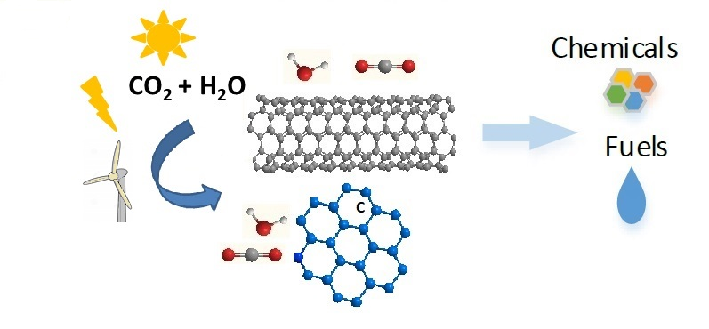
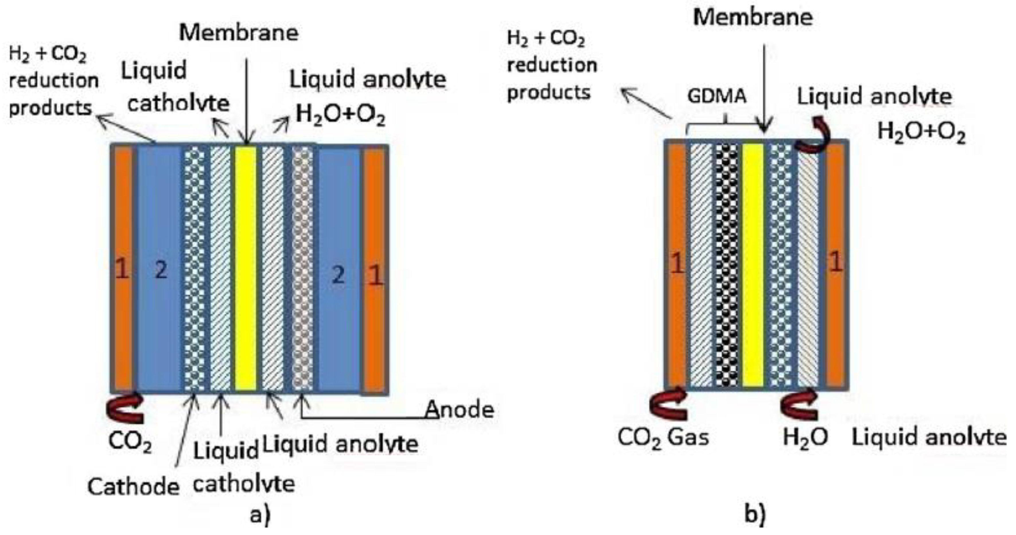
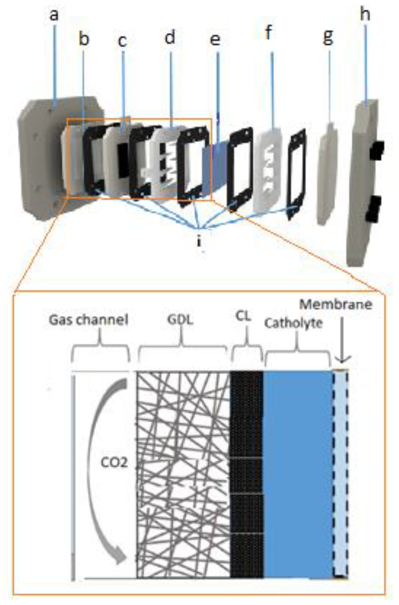
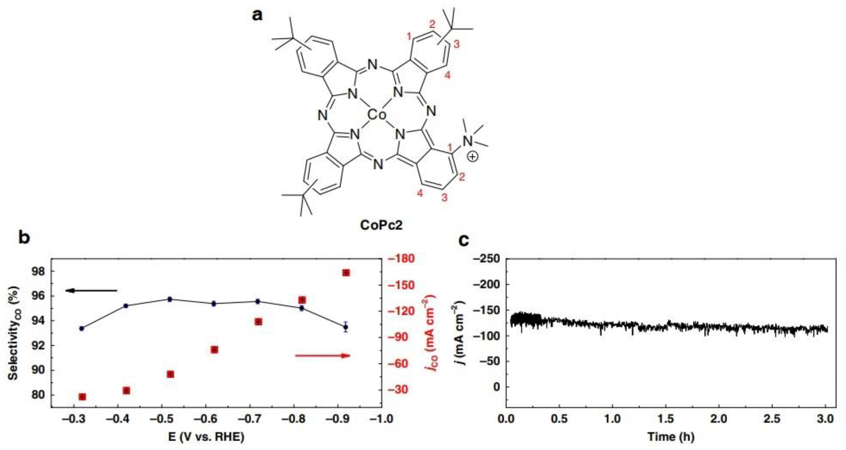
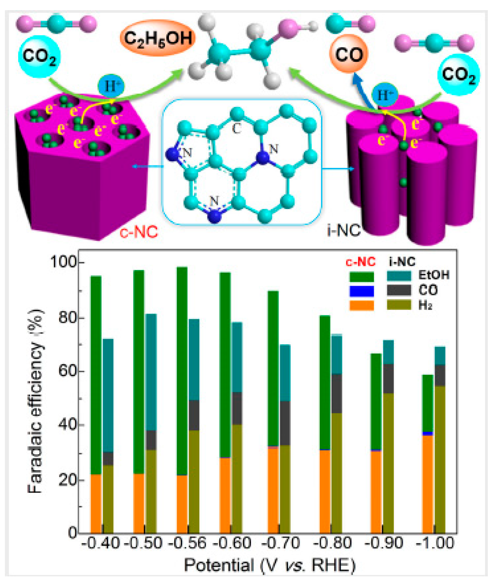
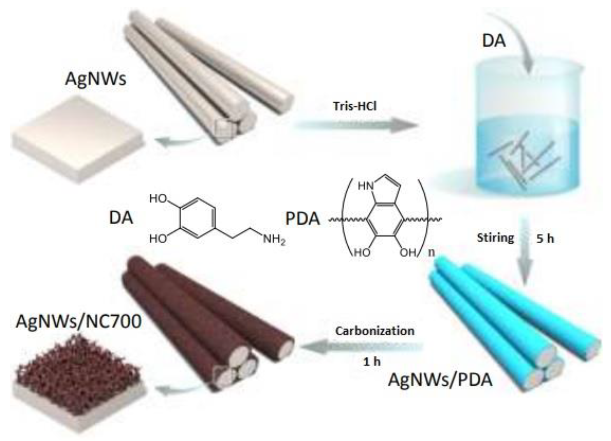
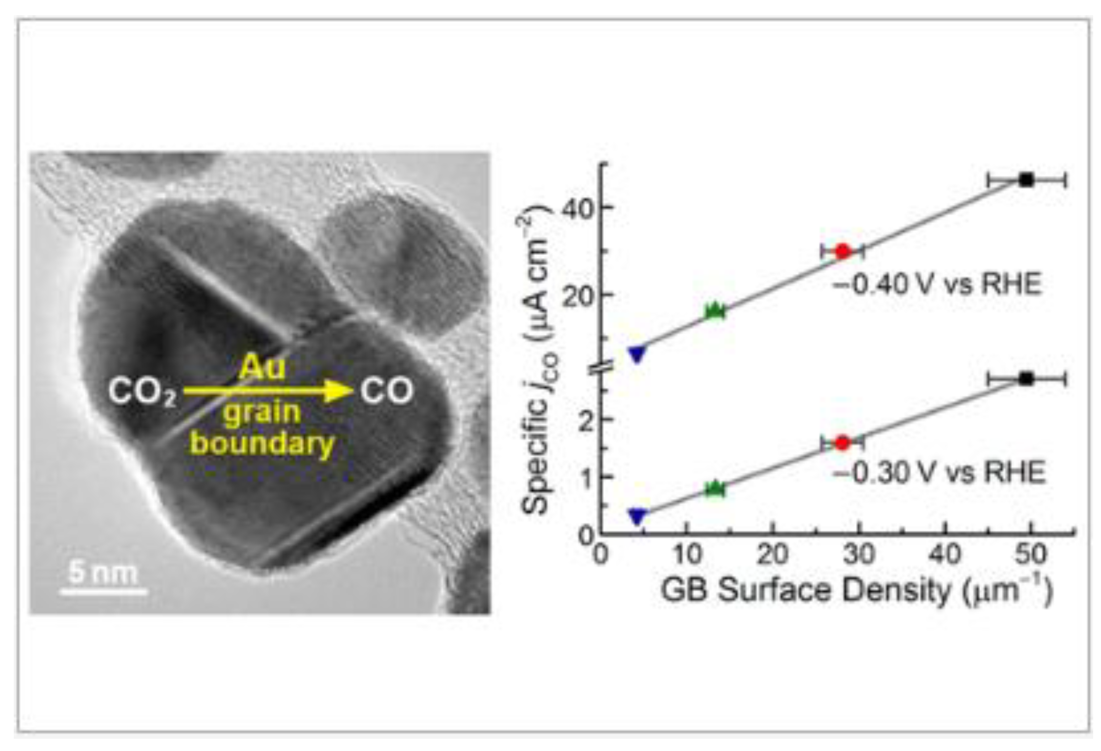
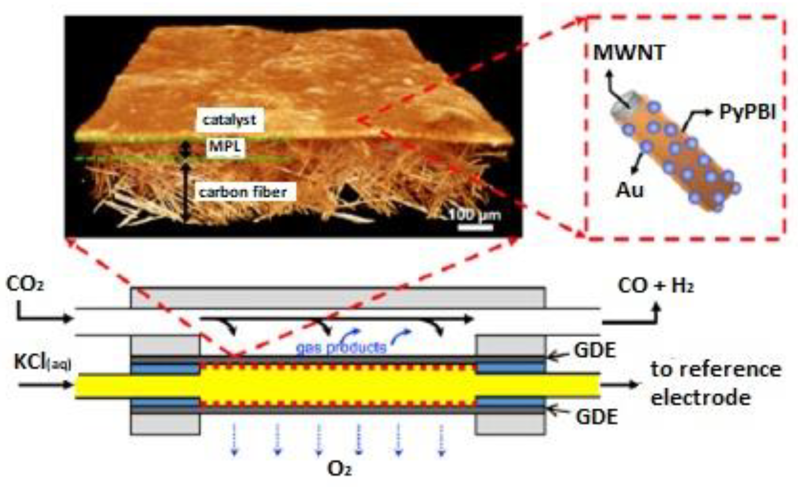
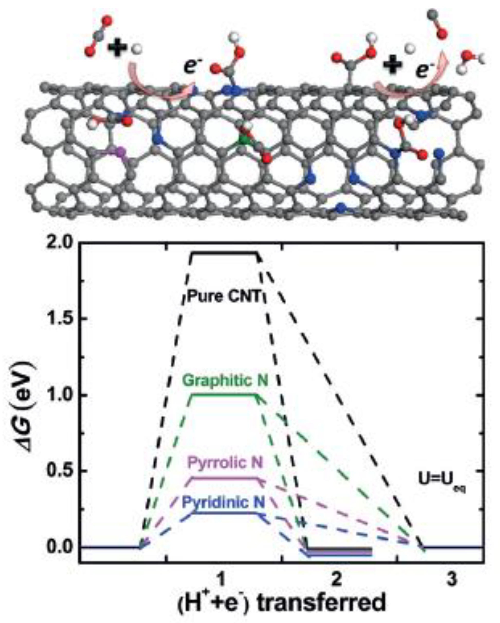
Table 1.
Performance of electrolytic systems using the carbon materials referred in this work.
| Types of Carbon | Catalyst | Current Density (mA/cm2) | Potential/ Voltage | CO2RR Products | Faradaic Efficiency | Reference |
|---|---|---|---|---|---|---|
| Supported Metal and Metal Derived Particles | ||||||
| Carbon Black | Pb on Vulcan 72 | 115 | −2.7 to −3.0V vs. SCE | Formic acid | 97% | Mahmood et al. [6] |
| Cu | 667 | −4.75 V vs. Ag/AgCL | Ethene | 53% | Cook et al. [11] | |
| Cu | 300 | −1.25 V vs. SHE | Ethylene and ethanol | - | Ikeda et al. [7] | |
| Ru-Pd alloys | 80 | −1.1V vs. SHE | Formic acid | 90% | Furuya et al. [10] | |
| Pt | 600 | −1.93 V vs. Ag/AgCL | Methane | 38.8% | Hara et al. [13] | |
| Au, 8 nm NP | 3A/g | −0.67 V vs. RHE | Carbon monoxide | 90% | Zhu et al. [19] | |
| Au 500 nm nanowires | 8 | −0.35 V vs. RHE | Carbon monoxide | 94% | Zhu et al. [20] | |
| Au25 Clusters | - | −1 V vs. RHE | Carbon monoxide | 100% | Kauffman et al. [21] | |
| Triangular Ag nanoplates | 1.25 | −0.86 V vs. RHE | Carbon monoxide | 97% | Liu et al. [22] | |
| Cysteamine anchored 5 nmAg nanoparticles | 1 | −0.35 V vs. RHE | Carbon monoxide | ~80% | Kim et al. [23] | |
| Core/Shell Cu/SnO2 Structure | 4.6 | −0.7 V vs. RHE | Carbon monoxide | 93% | Li et al. [24] | |
| Pd 5 nm nanoparticles | 2.2 to 4.15 | >−0.2 V vs. RHE | Formic acid | >95% | Min et al. [29] | |
| Sn nanoparticles | 200 | −1.4 V vs. Ag/AgCl/4 V cell voltage | Formic acid | 54.1% | Del Castillo et al. [30] | |
| Ni nitride | 23.3 | −0.90 V vs. RHE | Carbon monoxide | 92.5% | Hou et al. [31] | |
| Ag 20 nm nanoparticles | 200 | 3 V cell voltage | Carbon monoxide | 98% | Liu et al. [33] | |
| Molecular Catalysts | ||||||
| Co-Phthalocyanine | 80 | −4.39 V vs. Ag/AgCl | Carbon monoxide | 100% | Savinova et al. [35] | |
| Co-Phtahlocyanine | 137 22 | −2.2 V vs. SCE −1.5 V vs. SCE | Carbon monoxide | 14% 100% | Mahmood et al. [36] | |
| Co Phthalocyanine2 | 165 | −0.92 V vs. RHE | Carbon monoxide | 95% | Wang et al. [39] | |
| Mesoporous Carbon | Carbon nanospheres impregnated with Ni particles | - | −1.6 V vs. Ag/AgCl | C1-C4 hydrocarbons | 0.3% | Castelo-Quibén et al. [41] |
| Nitrogen doped mesoporous carbon | 0.25 | −0.56 V vs. RHE | Ethanol | 77% | Song et al. [43] | |
| mesoporous N-doped carbon | 6.8 | −0.58 V vs. RHE | Carbon monoxide | ~92% | Kuang et al. [44] | |
| Carbon Fibers | CoFPc immobilized on carbon cloth | 1–6 | 2–3 V cell voltage | Carbon monoxide | ~90% | Morlanés et al. [45] |
| fac-Mn(apbpy)(CO)3Br attached on carbon cloth | 0.9 | −1.35 V vs. Ag/AgCl | syngas | 60% for CO | Rotundo et al. [46] | |
| porphyrin and phthalocyanine | 70 | −1.5 V vs. SCE | Carbon monoxide | 70% | Magdesieva et al. [49] | |
| N-doped carbon nanofibers | 0.5 | −0.573 V vs. RHE | Carbon monoxide | 98% | Kumar et al. [50] | |
| N-doped carbon fibers with a core of Ag nanowires | - | −0.8 V vs. RHE | Carbon monoxide Hydrogen | 96% | Yang et al. [52] | |
| Au nanoparticles supported on graphene nanoribbon | ~4–6 | −0.47 V vs. RHE | Carbon monoxide | >60% | Rogers et al. [54] | |
| Graphene | Cu2O nanoparticles supported on graphene | - | −0.9 V vs. Ag/AgCl | Ethanol | 9.93% | Geioushy et al. [55] |
| N-doped graphene | 7.5 | −0.84 vs. Ag/AgCl | Formate | 70–63% | Wang et al. [57] | |
| N-doped 3D-graphene foam | 1.8 | −0.58 V vs. RHE | Carbon monoxide Formic acid | 70% 3.0% | Wu et al. [58] | |
| B-doped graphene | 0.5 | −1.4 V vs. SCE | Formate | 66% | Sreekanth et al. [56] | |
| N-doped graphene | - | −0.9 V vs. RHE | Formate | 65% | Li et al. [59] | |
| Cu nanoparticles dispersed on n-doped graphene | −0.9 V vs. RHE | Ethylene | 19% | Li et al. [59] | ||
| N-defective graphene | 1.3 | −0.6 V vs. RHE | Carbon monoxide | ~84% | Han et al. [60] | |
| Graphene Derivatives | Amine modified Au nanoparticles supported on rGO | 6 | −0.7 V vs. RHE | Carbon monoxide | >60% | Zhao et al. [64] |
| Cu nanowires wrapped in rGO | 8 | −1.25 V vs. RHE | Methane | 55% | Li et al. [65] | |
| Pt deposited on adenine-rGO | 0.5 | −0.3V vs. Ag/AgCl | Methanol | >85% | Hossein et al. [66] | |
| Cu2O/N-doped rGO | 12 | −1.4 V vs. RHE | Ethylene | 19.7% | Ning et al. [67] | |
| porphyrin/graphene framework | 1.68 | −0.54V vs. RHE | Carbon monoxide | 98.7% | Choi et al. [69] | |
| Vitamin B6 grafted on GO sheet | 0.25 | −0.4 V vs. RHE | Ethanol | 37% | Yuan et al. [70] | |
| iron porphyrin-based rGO hydrogel | 0.42 | −0.39 V vs. RHE | Carbon monoxide | 96% | Choi et al. [72] | |
| Au nanoparticles supported on MWCNT | 160 | −1.78 V vs. Ag/AgCl | Carbon monoxide | 60% | Jhong et al. [74] | |
| Au nanoparticles supported on MWCNT | 158 | −0.55 V vs. RHE | Carbon monoxide | 85% | Verma et al. [75] | |
| SnOx supported on MWCNT | 5–10 | −1.4 V vs. SCE | Formic acid | 60% | Zhao et al. [76] | |
| Carbon nanotubes | MWCNTs covered with a layer of Ag | 350 | −3 V cell voltage | Carbon monoxide | 95% | Ma et al. [77] |
| SnO2/MWCNT with 20%weight of SnO2 | 80 | −1.7 V vs. SCE | Formate | 27.2% | Bashir et al. [78] | |
| Immobilized Mn complex in Nafion/MWCNT | 2.65 | −15 V vs. SCE | Carbon monoxide | 24% | Walsh et al. [80] | |
| cobalt(II) chlorin complex | - | −1.1 V vs. NHE | Carbon monoxide | 89% | Aoi et al. [82] | |
| Co phthalocyanine funcionalised with CN groups anchored on CNT | 15 | −0.63 V vs. RHE −0.63 V vs. RHE | Carbon monoxide | >95% | Zhang et al. [84] | |
| CNT immobilized on cobalt polyphthalocyanine sheath | 18.7 | −0.5 V vs. RHE | Carbon monoxide | >80% | Han et al. [85] | |
| Co complex/CNT composite material | 9.3 | −0.48 V vs. RHE | Carbon monoxide | 100% | Wang et al. [86] | |
| CNT embedded in a carbon matrix | 6 | −0.8 V vs. RHE | Formate | 81% | Wang et al. [88] | |
| Nitrogen-doped carbon nanotubes | PEI-N-doped CNT | 7.2 | −1.8 V vs. SCE | Formate | 85% | Zhang et al. [87] |
| N-doped CNT | 1 | −0.8 V vs. RHE | Carbon monoxide | 80% | Wu et al. [89] | |
| N-doped CNT with pyridinic (1.1 at%) and graphitic (3.5 at%) | 2 | −1.05 V cell voltage (corrected for IR drop) | Carbon monoxide | 80% | Sharma et al. [91] | |
| N-doped carbon wrapped CNT | 0.5–0.1 | −0.5 V vs. RHE | Carbon monoxide | Cui et al. [93] | ||
| N-CNTs/SS | 2 | −1.1 V vs. Ag/AgCl | Carbon monoxide Hydrogen | 75% | Liu et al. [94] | |
© 2019 by the authors. Licensee MDPI, Basel, Switzerland. This article is an open access article distributed under the terms and conditions of the Creative Commons Attribution (CC BY) license (http://creativecommons.org/licenses/by/4.0/).
Share and Cite
MDPI and ACS Style
Messias, S.; Nunes da Ponte, M.; S. Reis-Machado, A. Carbon Materials as Cathode Constituents for Electrochemical CO2 Reduction—A Review. C 2019, 5, 83. https://0-doi-org.brum.beds.ac.uk/10.3390/c5040083
AMA Style
Messias S, Nunes da Ponte M, S. Reis-Machado A. Carbon Materials as Cathode Constituents for Electrochemical CO2 Reduction—A Review. C. 2019; 5(4):83. https://0-doi-org.brum.beds.ac.uk/10.3390/c5040083
Chicago/Turabian StyleMessias, Sofia, Manuel Nunes da Ponte, and Ana S. Reis-Machado. 2019. "Carbon Materials as Cathode Constituents for Electrochemical CO2 Reduction—A Review" C 5, no. 4: 83. https://0-doi-org.brum.beds.ac.uk/10.3390/c5040083
Note that from the first issue of 2016, this journal uses article numbers instead of page numbers. See further details here.