Electrochemical Evaluation of Directly Electrospun Carbide-Derived Carbon-Based Electrodes in Different Nonaqueous Electrolytes for Energy Storage Applications

Abstract
:1. Introduction
2. Experimental Section
2.1. Materials and Processes
2.2. Electrolytes
2.3. Electrochemical Characterization
3. Results and Discussion
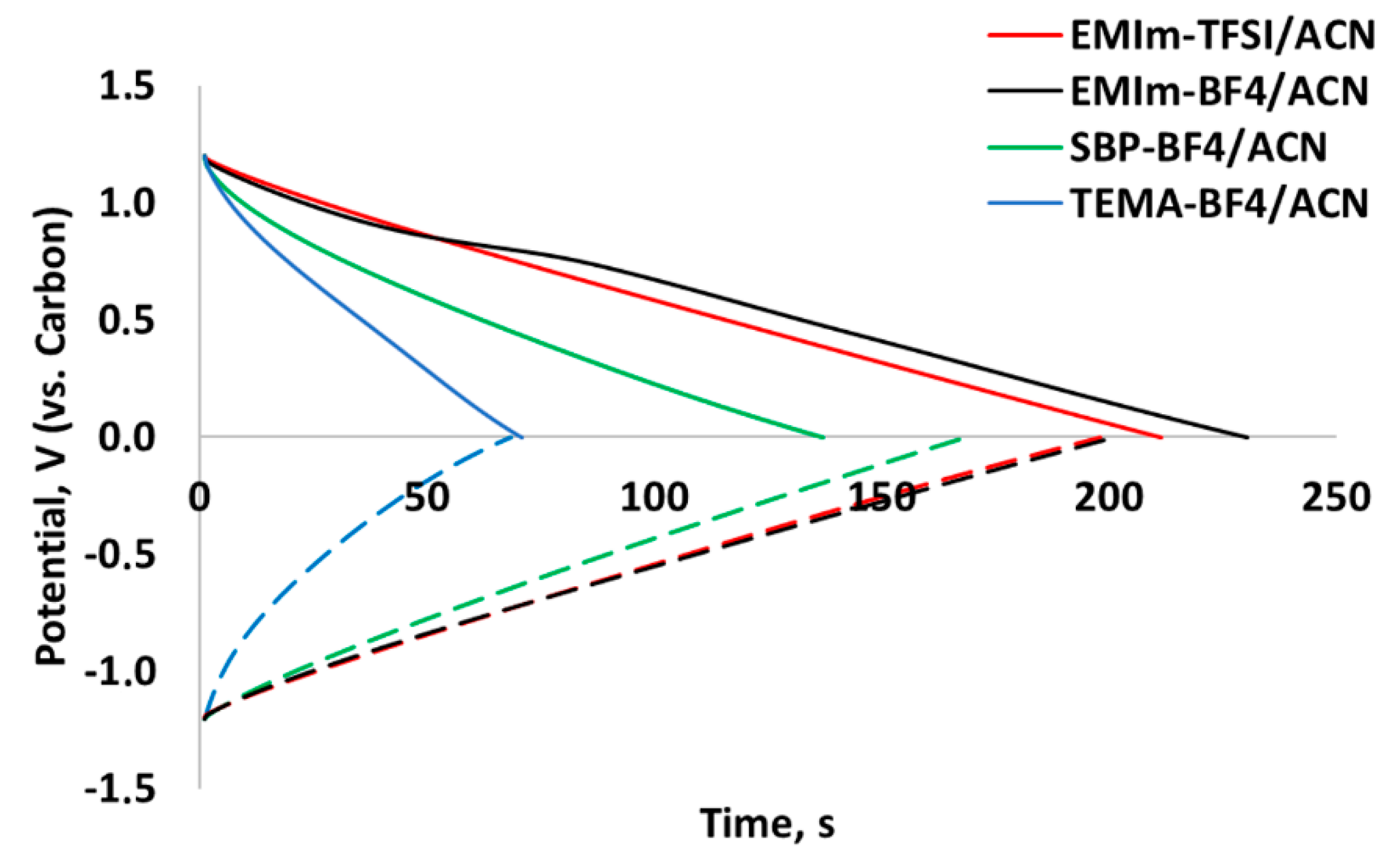
3.1. Galvanostatic Charge and Discharge
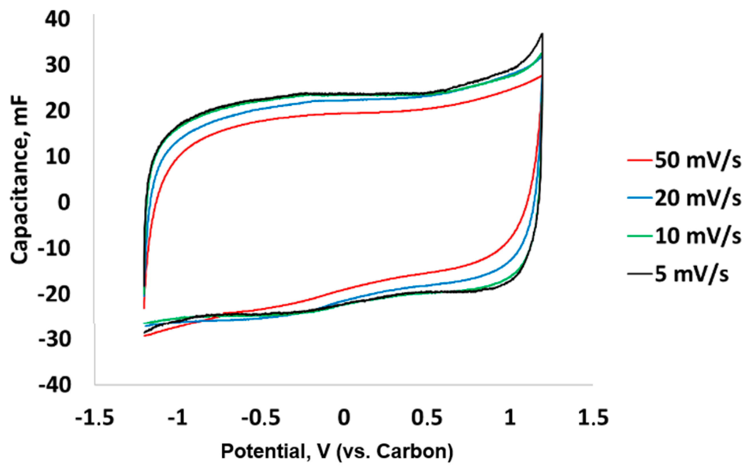
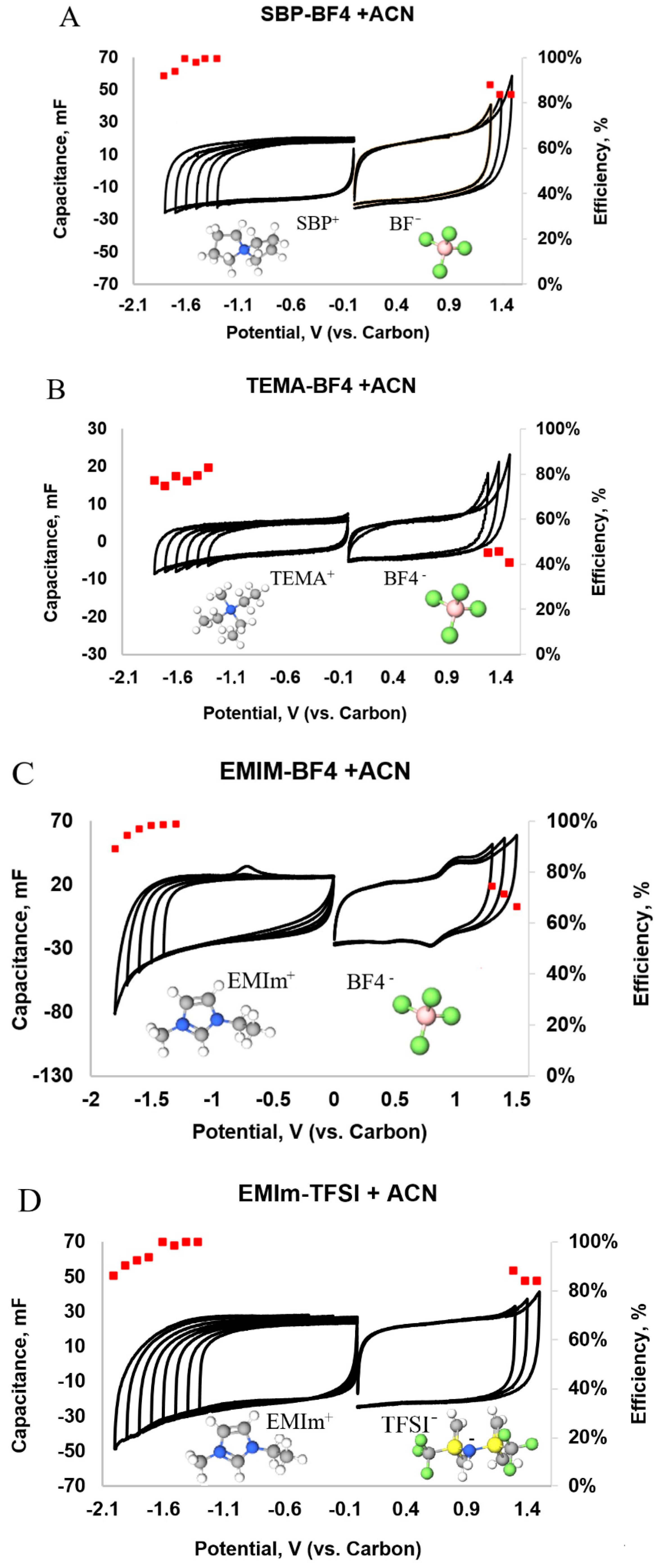
3.2. Cyclic Voltammetry
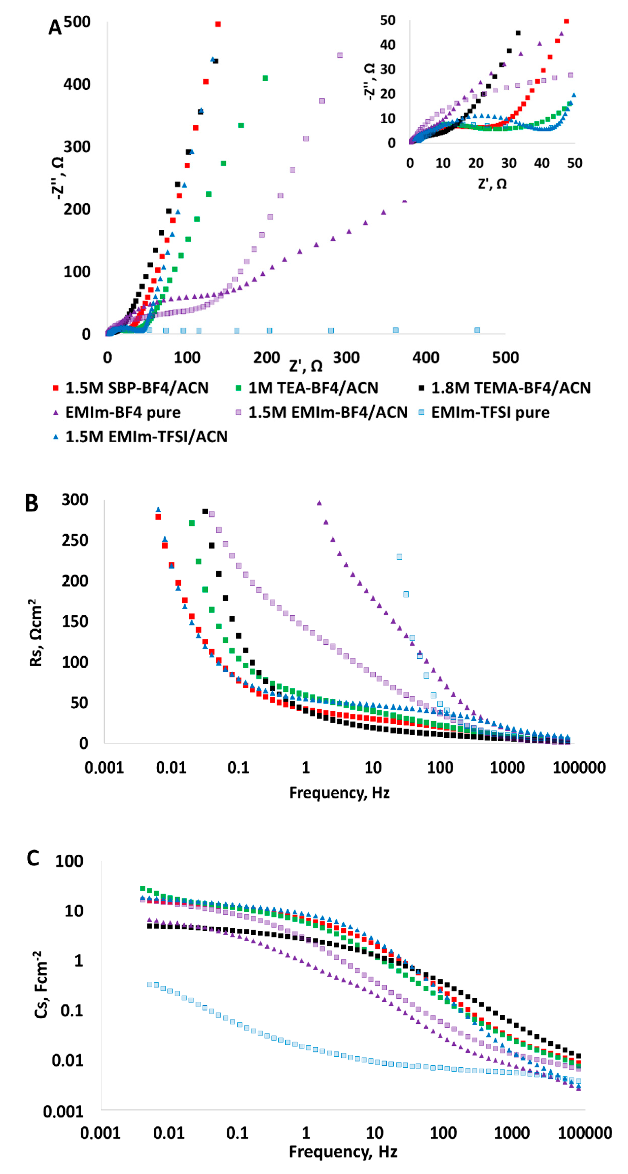
3.3. Electrochemical Impedance Spectroscopy
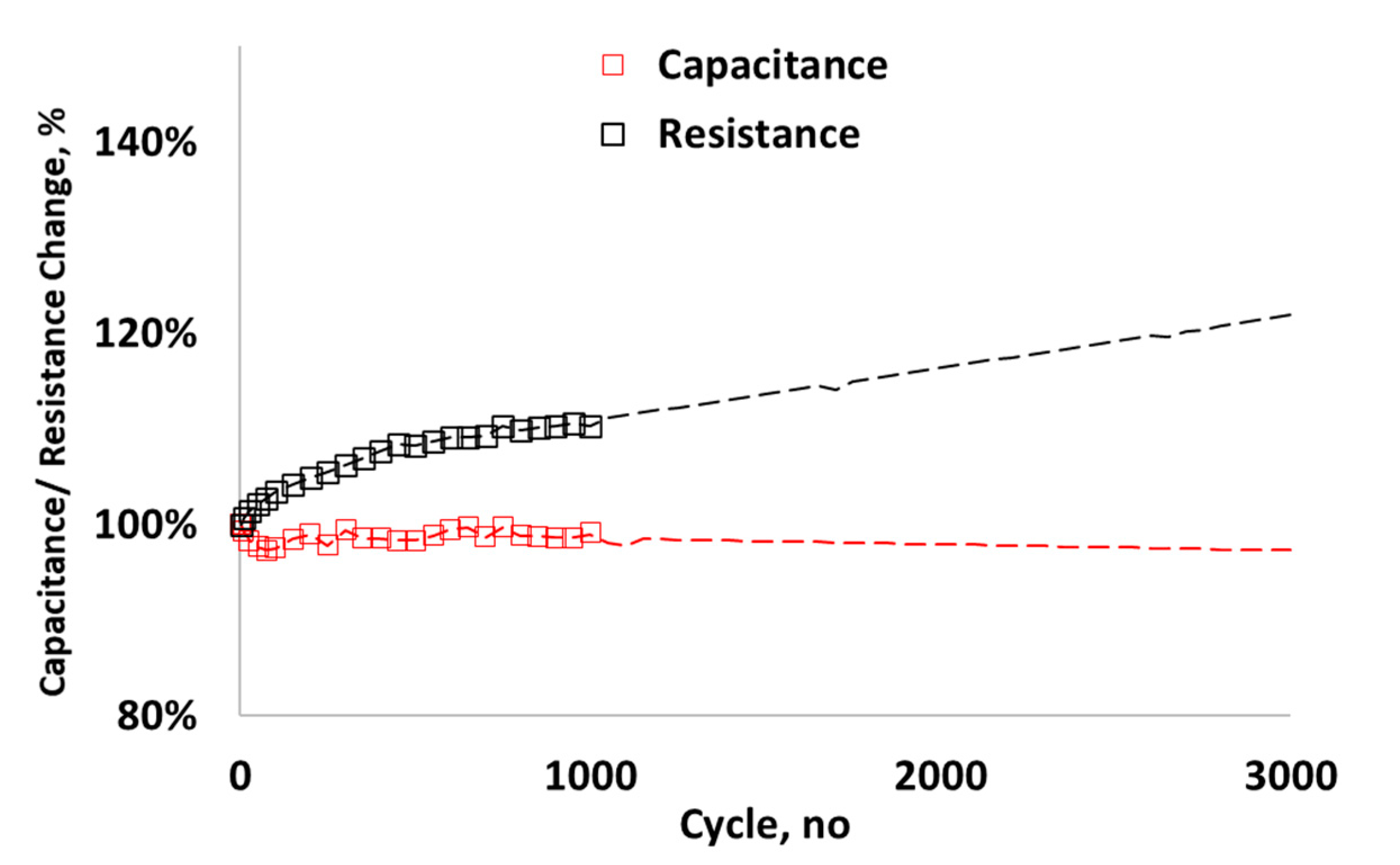
3.4. Cycle-Life
4. Conclusions
Author Contributions
Funding
Acknowledgments
Conflicts of Interest
References
- Libich, J.; Máca, J.; Vondrák, J.; Čech, O.; Sedlaříková, M. Supercapacitors: Properties and applications. J. Energy Storage 2018, 17, 224–227. [Google Scholar] [CrossRef]
- Pohlmann, S.; Lobato, B.; Centeno, T.A.; Balducci, A. The influence of pore size and surface area of activated carbons on the performance of ionic liquid based supercapacitors. Phys. Chem. Chem. Phys. 2013, 15, 17287. [Google Scholar] [CrossRef] [PubMed] [Green Version]
- Stan, A.-I.; Swierczynski, M.; Stroe, D.-I.; Teodorescu, R.; Andreasen, S.J. Lithium ion battery chemistries from renewable energy storage to automotive and back-up power applications—An overview. In Proceedings of the 2014 International Conference on Optimization of Electrical and Electronic Equipment (OPTIM), Brasov, Romania, 22 May 2014; pp. 713–720. [Google Scholar] [CrossRef]
- Burke, A.; Zhao, H. Applications of Supercapacitors in Electric and Hybrid Vehicles; Institute of Transportation Studies: Davis, CA, USA, 2015; p. 15. [Google Scholar]
- Radu, P.; Szelag, A.; Steczek, M. On-Board Energy Storage Devices with Supercapacitors for Metro Trains—Case Study Analysis of Application Effectiveness. Energies 2019, 12, 1291. [Google Scholar] [CrossRef] [Green Version]
- Brazis, V.; Latkovskis, L.; Grigans, L. Simulation of Trolleybus Traction Induction Drive with Supercapacitor Energy Storage System. Latv. J. Phys. Technol. Sci. 2010, 47, 33–47. [Google Scholar] [CrossRef]
- Kim, S.; Chou, P.H. Energy Harvesting with Supercapacitor-Based Energy Storage. In Smart Sensors and Systems; Lin, Y.-L., Kyung, C.-M., Yasuura, H., Liu, Y., Eds.; Springer International Publishing: Cham, Germany, 2015; pp. 215–241. ISBN 978-3-319-14710-9. [Google Scholar]
- Fahmi, M.I.; Rajkumar, R.K.; Arelhi, R.; Isa, D. Study on the effect of supercapacitors in solar PV system for rural application in Malaysia. In Proceedings of the 2015 50th International Universities Power Engineering Conference (UPEC), Stoke On Trent, UK, 1–4 September 2015; pp. 1–5. [Google Scholar] [CrossRef]
- Liudvinavičius, L. Supercapacitors: Theoretical and Practical Solutions; BoD–Books on Demand: Norderstedt, Germany, 2018; ISBN 978-1-78923-352-0. [Google Scholar]
- Käärik, M.; Arulepp, M.; Kook, M.; Kozlova, J.; Ritslaid, P.; Aruväli, J.; Mäeorg, U.; Sammelselg, V.; Leis, J. High-performance microporous carbon from deciduous wood-origin metal carbide. Microporous Mesoporous Mater. 2019, 278, 14–22. [Google Scholar] [CrossRef]
- Béguin, F.; Presser, V.; Balducci, A.; Frackowiak, E. Carbons and Electrolytes for Advanced Supercapacitors. Adv. Mater. 2014, 26, 2219–2251. [Google Scholar] [CrossRef]
- Zhong, C.; Deng, Y.; Hu, W.; Qiao, J.; Zhang, L.; Zhang, J. A review of electrolyte materials and compositions for electrochemical supercapacitors. Chem. Soc. Rev. 2015, 44, 7484–7539. [Google Scholar] [CrossRef]
- Balducci, A.; Dugas, R.; Taberna, P.L.; Simon, P.; Plée, D.; Mastragostino, M.; Passerini, S. High temperature carbon–carbon supercapacitor using ionic liquid as electrolyte. J. Power Sources 2007, 165, 922–927. [Google Scholar] [CrossRef] [Green Version]
- Martins, V.L.; Rennie, A.J.R.; Sanchez-Ramirez, N.; Torresi, R.M.; Hall, P.J. Improved Performance of Ionic Liquid Supercapacitors by using Tetracyanoborate Anions. ChemElectroChem 2018, 5, 598–604. [Google Scholar] [CrossRef]
- Keypour, H.; Noroozi, M.; Rashidi, A. An improved method for the purification of fullerene from fullerene soot with activated carbon, celite, and silica gel stationary phases. J. Nanostructure Chem. 2013, 3. [Google Scholar] [CrossRef] [Green Version]
- Arepalli, S.; Fireman, H.; Huffman, C.; Moloney, P.; Nikolaev, P.; Yowell, L.; Kim, K.; Kohl, P.A.; Higgins, C.D.; Turano, S.P.; et al. Carbon-nanotube-based electrochemical double-layer capacitor technologies for spaceflight applications. JOM 2005, 57, 26–31. [Google Scholar] [CrossRef]
- Cai, Y.; Qin, Z.; Chen, L. Effect of electrolytes on electrochemical properties of graphene sheet covered with polypyrrole thin layer. Prog. Nat. Sci. Mater. Int. 2011, 21, 460–466. [Google Scholar] [CrossRef] [Green Version]
- Arulepp, M.; Leis, J.; Lätt, M.; Miller, F.; Rumma, K.; Lust, E.; Burke, A.F. The advanced carbide-derived carbon based supercapacitor. J. Power Sources 2006, 162, 1460–1466. [Google Scholar] [CrossRef]
- Inamuddin; Boddula, R.; Ahamed, M.I.; Asiri, A.M. Supercapacitor Technology: Materials, Processes and Architectures; Materials Research Forum LLC: Millersville, PA, USA, 2019; ISBN 978-1-64490-049-9. [Google Scholar]
- Vatamanu, J.; Hu, Z.; Bedrov, D.; Perez, C.; Gogotsi, Y. Increasing Energy Storage in Electrochemical Capacitors with Ionic Liquid Electrolytes and Nanostructured Carbon Electrodes. J. Phys. Chem. Lett. 2013, 4, 2829–2837. [Google Scholar] [CrossRef]
- Käärik, M.; Arulepp, M.; Käärik, M.; Maran, U.; Leis, J. Characterization and prediction of double-layer capacitance of nanoporous carbon materials using the Quantitative nano-Structure-Property Relationship approach based on experimentally determined porosity descriptors. Carbon 2019. [Google Scholar] [CrossRef]
- Käärik, M.; Arulepp, M.; Kook, M.; Mäeorg, U.; Kozlova, J.; Sammelselg, V.; Perkson, A.; Leis, J. Characterisation of steam-treated nanoporous carbide-derived carbon of TiC origin: Structure and enhanced electrochemical performance. J. Porous Mater. 2018, 25, 1057–1070. [Google Scholar] [CrossRef]
- Leis, J.; Arulepp, M.; Kuura, A.; Lätt, M.; Lust, E. Electrical double-layer characteristics of novel carbide-derived carbon materials. Carbon 2006, 44, 2122–2129. [Google Scholar] [CrossRef]
- Torop, J.; Palmre, V.; Arulepp, M.; Sugino, T.; Asaka, K.; Aabloo, A. Flexible supercapacitor-like actuator with carbide-derived carbon electrodes. Carbon 2011, 49, 3113–3119. [Google Scholar] [CrossRef]
- Ewert, J.-K.; Weingarth, D.; Denner, C.; Friedrich, M.; Zeiger, M.; Schreiber, A.; Jäckel, N.; Presser, V.; Kempe, R. Enhanced capacitance of nitrogen-doped hierarchically porous carbide-derived carbon in matched ionic liquids. J. Mater. Chem. A 2015, 3, 18906–18912. [Google Scholar] [CrossRef] [Green Version]
- Dyatkin, B.; Gogotsi, O.; Malinovskiy, B.; Zozulya, Y.; Simon, P.; Gogotsi, Y. High capacitance of coarse-grained carbide derived carbon electrodes. J. Power Sources 2016, 306, 32–41. [Google Scholar] [CrossRef] [Green Version]
- Krüner, B.; Odenwald, C.; Tolosa, A.; Schreiber, A.; Aslan, M.; Kickelbick, G.; Presser, V. Carbide-derived carbon beads with tunable nanopores from continuously produced polysilsesquioxanes for supercapacitor electrodes. Sustain. Energy Fuels 2017, 1, 1588–1600. [Google Scholar] [CrossRef]
- Beguin, F.; Frackowiak, E. Supercapacitors: Materials, Systems, and Applications; John Wiley & Sons: Hoboken, NJ, USA, 2013; ISBN 978-3-527-64668-5. [Google Scholar]
- Lin, R.; Taberna, P.-L.; Chmiola, J.; Guay, D.; Gogotsi, Y.; Simon, P. Microelectrode Study of Pore Size, Ion Size, and Solvent Effects on the Charge/Discharge Behavior of Microporous Carbons for Electrical Double-Layer Capacitors. J. Electrochem. Soc. 2009, 156, A7. [Google Scholar] [CrossRef] [Green Version]
- Cheng, W.; Yu, Q.; Qiu, Z.; Yan, Y. Effects of different ionic liquids on the electrospinning of a polyacrylonitrile polymer solution. J. Appl. Polym. Sci. 2013, 130, 2359–2368. [Google Scholar] [CrossRef]
- Malmberg, S.; Arulepp, M.; Savest, N.; Tarasova, E.; Vassiljeva, V.; Krasnou, I.; Käärik, M.; Mikli, V.; Krumme, A. Directly electrospun electrodes for electrical double-layer capacitors from carbide-derived carbon. J. Electrost. 2020, 103, 103396. [Google Scholar] [CrossRef]
- Yang, T.; Yao, Y.; Lin, Y.; Wang, B.; Xiang, R.; Wu, Y.; Wu, D. Electrospinning of polyacrylonitrile fibers from ionic liquid solution. Appl. Phys. A 2010, 98, 517–523. [Google Scholar] [CrossRef]
- Levitt, A.S.; Alhabeb, M.; Hatter, C.B.; Sarycheva, A.; Dion, G.; Gogotsi, Y. Electrospun MXene/carbon nanofibers as supercapacitor electrodes. J. Mater. Chem. A 2018, 7, 269–277. [Google Scholar] [CrossRef]
- Miao, Y.-E.; Yan, J.; Huang, Y.; Fan, W.; Liu, T. Electrospun polymer nanofiber membrane electrodes and an electrolyte for highly flexible and foldable all-solid-state supercapacitors. RSC Adv. 2015, 5, 26189–26196. [Google Scholar] [CrossRef]
- Salles, V.; Bernard, S.; Brioude, A.; Cornu, D.; Miele, P. A new class of boron nitride fibers with tunable properties by combining an electrospinning process and the polymer-derived ceramics route. Nanoscale 2010, 2, 215–217. [Google Scholar] [CrossRef]
- Hao, F.; Lin, H. Recent molecular engineering of room temperature ionic liquid electrolytes for mesoscopic dye-sensitized solar cells. RSC Adv. 2013, 3, 23521. [Google Scholar] [CrossRef]
- Prabaharan, S.R.S.; Michael, M.S. Nanotechnology in Advanced Electrochemical Power Sources; CRC Press: Boca Raton, FL, USA, 2014; ISBN 978-981-4241-43-4. [Google Scholar]
- Saito, M.; Kawaharasaki, S.; Ito, K.; Yamada, S.; Hayamizu, K.; Seki, S. Strategies for fast ion transport in electrochemical capacitor electrolytes from diffusion coefficients, ionic conductivity, viscosity, density and interaction energies based on HSAB theory. RSC Adv. 2017, 7, 14528–14535. [Google Scholar] [CrossRef] [Green Version]
- Cho, J.; Shin, W.-K.; Kim, D.-W.; Kim, Y.R.; Lee, B.J.; Kim, S.-G. Electrochemical characterization of electric double layer capacitors assembled with pyrrolidinium-based ionic liquid electrolytes. J. Electrochem. Sci. Technol. 2016, 7, 199–205. [Google Scholar] [CrossRef]
- Bashid, H.A.A.; Lim, H.N.; Hafiz, S.M.; Andou, Y.; Altarawneh, M.; Jiang, Z.T.; Huang, N.M. 16-Modification of Carbon-Based Electroactive Materials for Supercapacitor Applications. In Carbon-Based Polymer Nanocomposites for Environmental and Energy Applications; Ismail, A.F., Goh, P.S., Eds.; Elsevier: Amsterdam, The Netherlands, 2018; pp. 393–413. ISBN 978-0-12-813574-7. [Google Scholar]
- Zhang, E.; Fulik, N.; Paasch, S.; Borchardt, L.; Kaskel, S.; Brunner, E. Ionic liquid—Electrode materials interactions studied by NMR spectroscopy, cyclic voltammetry, and impedance spectroscopy. Energy Storage Mater. 2019, 19, 432–438. [Google Scholar] [CrossRef]
- Gualous, H.; Louahlia-Gualous, H.; Gallay, R.; Miraoui, A. Supercapacitor thermal modeling and characterization in transient state for industrial applications. IEEE Trans. Ind. Appl. 2009, 45, 1035–1044. [Google Scholar] [CrossRef]
- Stoller, M.D.; Ruoff, R.S. Best practice methods for determining an electrode material’s performance for ultracapacitors. Energy Environ. Sci. 2010, 3, 1294. [Google Scholar] [CrossRef]
- Tõnurist, K.; Vaas, I.; Thomberg, T.; Jänes, A.; Kurig, H.; Romann, T.; Lust, E. Application of multistep electrospinning method for preparation of electrical double-layer capacitor half-cells. Electrochim. Acta 2014, 119, 72–77. [Google Scholar] [CrossRef]
- Ruschhaupt, P.; Pohlmann, S.; Varzi, A.; Passerini, S. Determining realistic electrochemical stability windows of electrolytes for electrical double layer capacitors. Batter. Supercaps 2020, 3, 698–707. [Google Scholar] [CrossRef]
- Xu, K. Toward Reliable Values of Electrochemical Stability Limits for Electrolytes. J. Electrochem. Soc. 1999, 146, 4172. [Google Scholar] [CrossRef]
- Weingarth, D.; Noh, H.; Foelske-Schmitz, A.; Wokaun, A.; Kötz, R. A reliable determination method of stability limits for electrochemical double layer capacitors. Electrochim. Acta 2013, 103, 119–124. [Google Scholar] [CrossRef]
- Kreczanik, P.; Venet, P.; Hijazi, A.; Clerc, G. Study of Supercapacitor Aging and Lifetime Estimation According to Voltage, Temperature, and RMS Current. IEEE Trans. Ind. Electron. 2014, 61, 4895–4902. [Google Scholar] [CrossRef]
- Gao, Q. Optimizing Carbon/Carbon Supercapacitors in Aqueous and Organic Electrolytes. Ph.D. Thesis, Université d’Orléans, Orléans, France, 2013. [Google Scholar]


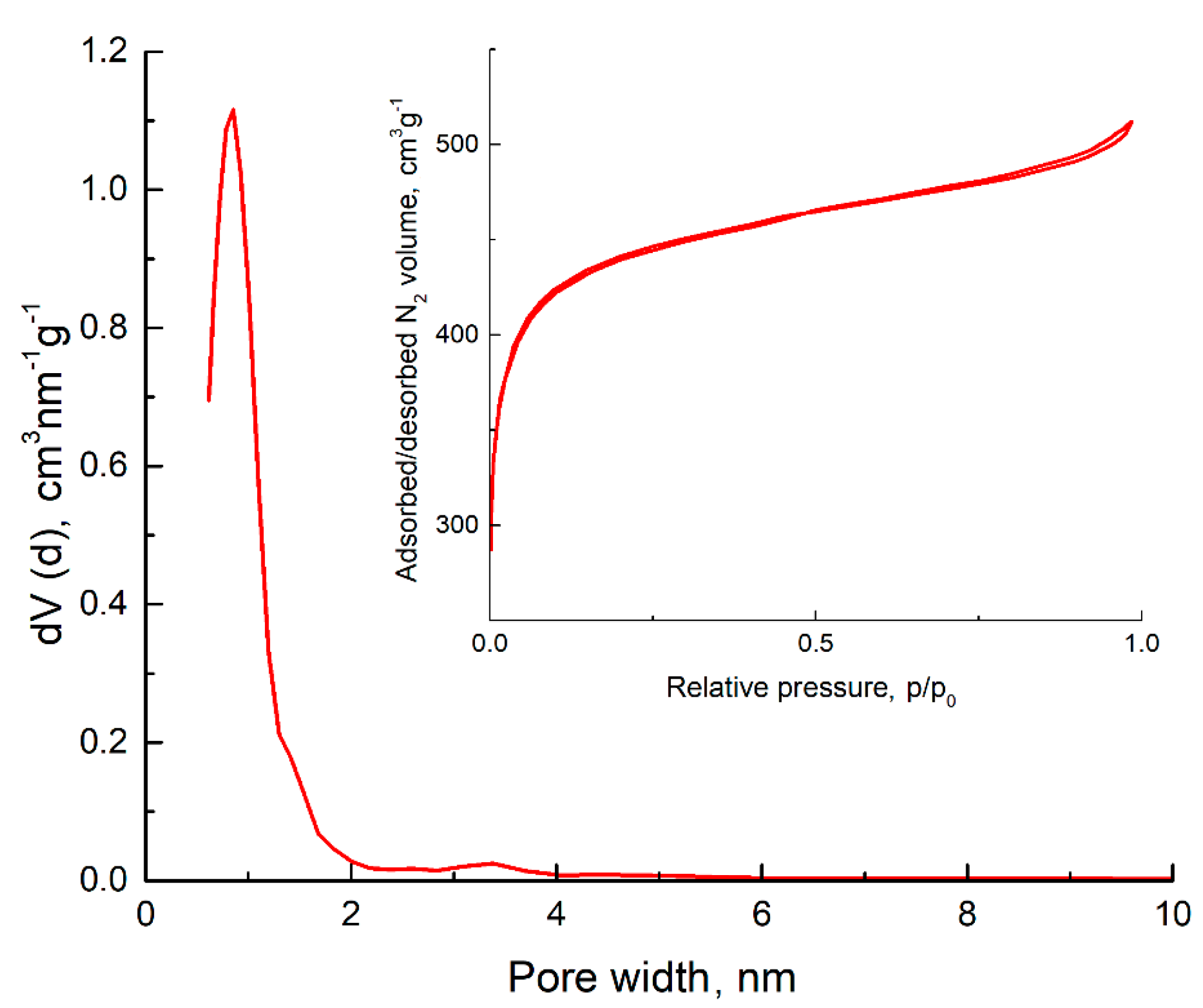
| Sample | SBET, m2 g−1 | Vµ, cm3 g−1 | Vtot, cm3 g−1 | APS nm |
|---|---|---|---|---|
| CDC | 1560 | 0.71 | 0.82 | 0.95 |
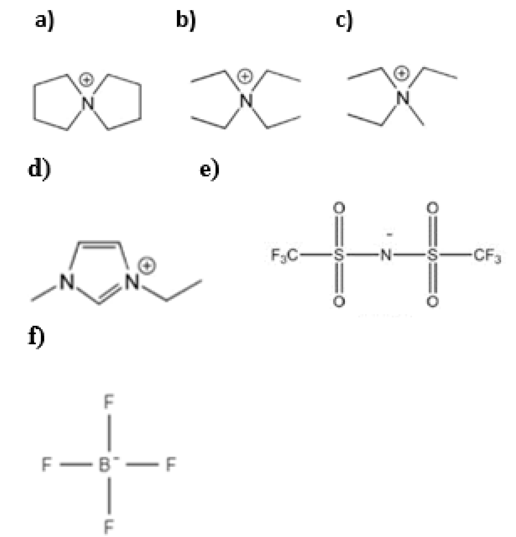
| Acronym | Chemical Formula | Ionic Radii, nm | Concentration in Acetonitrile, M (in This Study) | Reference |
|---|---|---|---|---|
| TEA+ | (C2H5)4N+ | 0.670 | 1 | [37] |
| TEMA+ | (C2H5)3CH3N+ | 0.327 | 1.8 | [38] |
| EMIm+ | C6H11N2+ | 0.326 | 1.5 | [39] |
| SBP+ | C8H16N+ | 0.420 | 1.5 | [21] |
| BF4− | BF4− | 0.480 | variable | [29] |
| TFSI− | (CF3SO2)2N− | 0.227 | 1.5 | [39] |
| Electrolyte | Electrode Coat Weight | Positively Charged Electrode | Negatively Charged Electrode | ||||
|---|---|---|---|---|---|---|---|
| g m−2 | mF cm−2 | F cm−3 | F g−1 | mF cm−2 | F cm−3 | F g−1 | |
| EMIm-TFSI/ACN | 2.29 | 20.6 | 10.3 | 89.8 | 20.6 | 10.3 | 89.8 |
| SBP-BF4/ACN | 1.83 | 14.4 | 14.4 | 78.5 | 19.7 | 9.9 | 95.3 |
| TEMA-BF4/ACN | 1.02 | 5.7 | 2.8 | 70.8 | 6.9 | 2.3 | 55.8 |
| EMIm-BF4/ACN | 2.29 | 24.2 | 12.1 | 105.6 | 19.7 | 9.9 | 76.2 |
© 2020 by the authors. Licensee MDPI, Basel, Switzerland. This article is an open access article distributed under the terms and conditions of the Creative Commons Attribution (CC BY) license (http://creativecommons.org/licenses/by/4.0/).
Share and Cite
Malmberg, S.; Arulepp, M.; Tarasova, E.; Vassiljeva, V.; Krasnou, I.; Krumme, A. Electrochemical Evaluation of Directly Electrospun Carbide-Derived Carbon-Based Electrodes in Different Nonaqueous Electrolytes for Energy Storage Applications. C 2020, 6, 59. https://0-doi-org.brum.beds.ac.uk/10.3390/c6040059
Malmberg S, Arulepp M, Tarasova E, Vassiljeva V, Krasnou I, Krumme A. Electrochemical Evaluation of Directly Electrospun Carbide-Derived Carbon-Based Electrodes in Different Nonaqueous Electrolytes for Energy Storage Applications. C. 2020; 6(4):59. https://0-doi-org.brum.beds.ac.uk/10.3390/c6040059
Chicago/Turabian StyleMalmberg, Siret, Mati Arulepp, Elvira Tarasova, Viktoria Vassiljeva, Illia Krasnou, and Andres Krumme. 2020. "Electrochemical Evaluation of Directly Electrospun Carbide-Derived Carbon-Based Electrodes in Different Nonaqueous Electrolytes for Energy Storage Applications" C 6, no. 4: 59. https://0-doi-org.brum.beds.ac.uk/10.3390/c6040059