
Enhanced Performance of Pt Nanoparticles on Ni-N Co-Doped Graphitized Carbon for Oxygen Reduction Reaction in Polymer Electrolyte Membrane Fuel Cells


1
School of Food Biotechnology and Chemical Engineering, Hankyong National University, Anseong-si 17579, Korea
2
Research Center of Chemical Technology, Hankyong National University, Anseong-si 17579, Korea
Catalysts 2021, 11(8), 909; https://0-doi-org.brum.beds.ac.uk/10.3390/catal11080909
Submission received: 20 June 2021
/
Revised: 19 July 2021
/
Accepted: 27 July 2021
/
Published: 28 July 2021
(This article belongs to the Special Issue Novel Catalyst Materials for Low-Temperature Fuel Cells and Electrolyzers)
Abstract
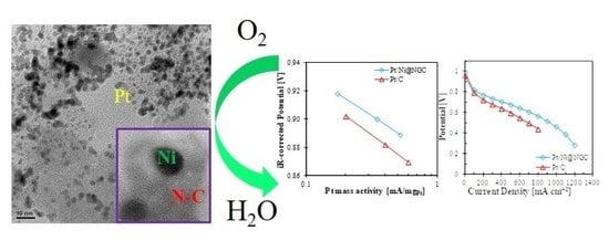
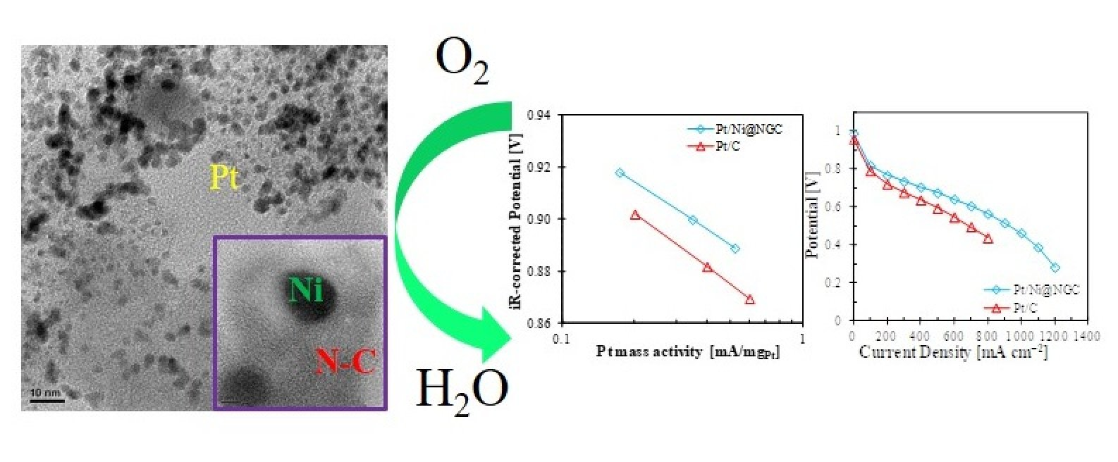
:Since the reaction rate and cost for cathodic catalyst in polymer electrolyte membrane fuel cells are obstacles for commercialization, the high-performance catalyst for oxygen reduction reaction is necessary. The Ni encapsulated with N-doped graphitic carbon (Ni@NGC) prepared with ethylenediamine and carbon black is employed as an efficient support for the oxygen reduction reaction. Characterizations show that the Ni@NGC has a large surface area and mesoporous structure that is suitable to the support for the Pt catalyst. The catalyst structure is identified and the size of Pt nanoparticles distributed in the narrow range of 2–3 nm. Four different nitrogen species are doped properly into graphitic carbon structure. The Pt/Ni@NGC shows higher performance than the commercial Pt/C catalyst in an acidic electrolyte. The mass activity of the Pt/Ni@NGC in fuel cell tests exhibits over 1.5 times higher than that of commercial Pt/C catalyst. The Pt/Ni@NGC catalyst at low Pt loading exhibits 47% higher maximum power density than the Pt/C catalyst under H2-air atmosphere. These results indicate that the Ni@NGC as a support is significantly beneficial to improving activity.
1. Introduction
In a few decades, polymer electrolyte membrane fuel cells (PEMFCs) have rapidly developed and been considered as a promising candidate for the replacement of fossil fuels due to eco-friendly and highly efficient energy systems. Pt is known as the most efficient and active catalyst for the oxygen reduction reaction (ORR) [1,2]. However, there are significant issues for commercialization. Since Pt is a costly and scarce resource, it is required to use a small quantity and increase the catalytic performance.
Recently, the N-doped carbon structure has attracted much interest in the field of electrochemical energy conversion and storage due to its greater electron mobility like n-type or metallic behavior than un-doped carbon nanostructures [3]. Furthermore, doping nitrogen efficiently implants chemically active sites for catalysis and also plays a role in deposition sites for metal nanoparticle deposition. It has been reported that nitrogen-doped carbon as a support can increase the activity of a Pt catalyst toward the ORR [4,5,6,7]. Since those advantages of nitrogen-doped carbon structure were discovered, researchers have tried to replace the carbon black with nitrogen-doped carbon material as a support of electro-catalyst in PEMFCs [8,9].
Wang et al. reported that Pt@NiNC with low Pt loading (8 wt%) prepared by the galvanic replacement reaction exhibited the synergistic effect of Pt particles near atomic Ni–N–C complexes [10]. The Pt nanoparticles on Pt@NiNC carried more positive charges than the Pt foil, which indicated that the Pt atoms existed in the metallic form. Also, we demonstrated that the metallic Pt percentage of Pt nanoparticles anchored on N-doped carbon was higher than that on the carbon black support since the pyridinic-N played a role of oxide-cleanser [11]. Those results supported a synergistic effect between Pt nanoparticles and N-doped carbon structure.
Pt electrocatalysts grafted, hierarchical mesoporous carbon nanofibers (Pt/MPCNFs) prepared using electrospinning showed even higher onset potential, half-wave potential, and limiting current density than the commercial Pt/C [12]. In the long-term stability test, it exhibited stable performance after 10,000 potential cycles. Researchers believed that high electrocatalytic activity was attributed to the uncommon ultrathin nanofibers with 3D mesoporous structure, high electrical conductivity, high specific surface area, homogeneously distributed Pt nanoparticles, and optimal nitrogen doping. Park et al. synthesized the FeNC support by a hard template method with two different sized SiO2 beads and phthalocyanine as N and carbon sources [13]. The Pt nanoparticles with four different loadings (5, 10, 20, 30 wt%) on the FeNC with a bimodal porous carbon nanostructure were deposited using an electron beam radiation method. The catalysts showed the following order of activity for the ORR: Pt30/FeNC > Pt20/FeNC > Pt10/FeNC > Pt5/FeNC > Pt20/C, which indicated that the Pt/FeNC catalysts outperformed Pt20/C. They believed that the FeNC adjusted the electronic structure of Pt and the synergistic effect of active sites on Pt and FeNC catalysts contributed to the enhanced kinetic activity of the Pt/FeNC over Pt20/C.
Besides, Pt alloy catalysts on N-doped carbon have been reported. Pt3Fe1/NCB, Pt3Ni1/NCB, and Pt3Pd1/NCB catalysts were prepared by an ethylene glycol method [14]. The researchers indicated that the onset potential of Pt3M1/NCB was shifted to a positive direction due to N doping. The effect of electron-rich N doping on cell performance might be varied with the work function and electronegativity of the transition metals (Fe, Ni, and Pd). It was found that quaternary-N played a significant role in the activity for the ORR and cell performance. Quaternary PtRuFeCo nanoparticles were deposited on N-doped graphene and evaluated for the ORR and methanol oxidation reaction [15]. Results indicated that doping influenced the small catalyst particle size with narrow distribution and good dispersion, the electron transfer from graphene matrix to oxygen, weakness of O–O bond, and strong metal-support interaction, causing reducing agglomeration of nanoparticles.
Density functional theory (DFT) calculations indicated that nitrogen doping might significantly increase the binding strength of Pt13 particles on the graphene surface [16]. It exhibited that the improved binding strength of the Pt13 cluster is ascribed to the activation of the carbon atoms near the nitrogen atoms, while the d states of the Pt13 cluster hybridize with the sp2 dangling bonds of the nitrogen atoms. The adsorption energy of O on Pt13 on NC was significantly weakened as compared to freestanding Pt13 nanoparticles. Thus, N-doped carbon can be a promising support to increase the catalytic activity for the ORR.
In this study, the facile and efficient nitrogen-containing carbon material is investigated [17,18,19,20,21,22]. The hybrid cathode catalysts are a combination of active Ni encapsulated with N-doped graphitic carbon (Ni@NGC) catalysts and platinum for the ORR. Along with its benefit to the catalyst activity, the Ni@NGC can boost the activity of the Pt through synergistic effects. We performed the Pt deposition on the novel carbon support and evaluated the performance and its origin. In order to elucidate the synergetic effect of nitrogen in support, the physical and electrochemical analyses were carried out on the supports and Pt catalysts.
2. Results and Discussion
2.1. Morphology and Physical Characterization of Ni@NGC
Figure 1a,b exhibits the nitrogen adsorption-desorption isotherms and Barrett–Joyner–Halenda (BJH) pore size distribution (PSD) curves of oxidized carbon black (ox-KB) and Ni@NGC. The specific surface area of Ni@NGC was 425 m2 g−1, while the ox-KB had 634 m2 g−1. The change of specific surface area was also found in the previous results [23]. After pyrolysis, the total pore volume was reduced from 0.846 to 0.688 cm3 g−1 and the peak pore diameter, which yields the peak differential pore volume in BJH PSD, as shown in Figure 1b, was slightly shifted from 3.9 (ox-KB) to 3.5 nm (Ni@NGC). The result could be revealed by the formation of the graphitized carbon layer derived from the Ni-EDA chelate and the shrinkage of the carbon frameworks due to the high-temperature pyrolysis [24,25]. The isotherms of the ox-KB and Ni@NGC corresponded to Type IV according to IUPAC classification. A hysteresis loop with sharp adsorption and desorption branches in a P/P0 range of 0.4–0.8 is observed in the isotherms. Besides, nitrogen uptake is observed at a relatively high P/P0 of 0.94–1.0, which indicates the presence of mesopores.
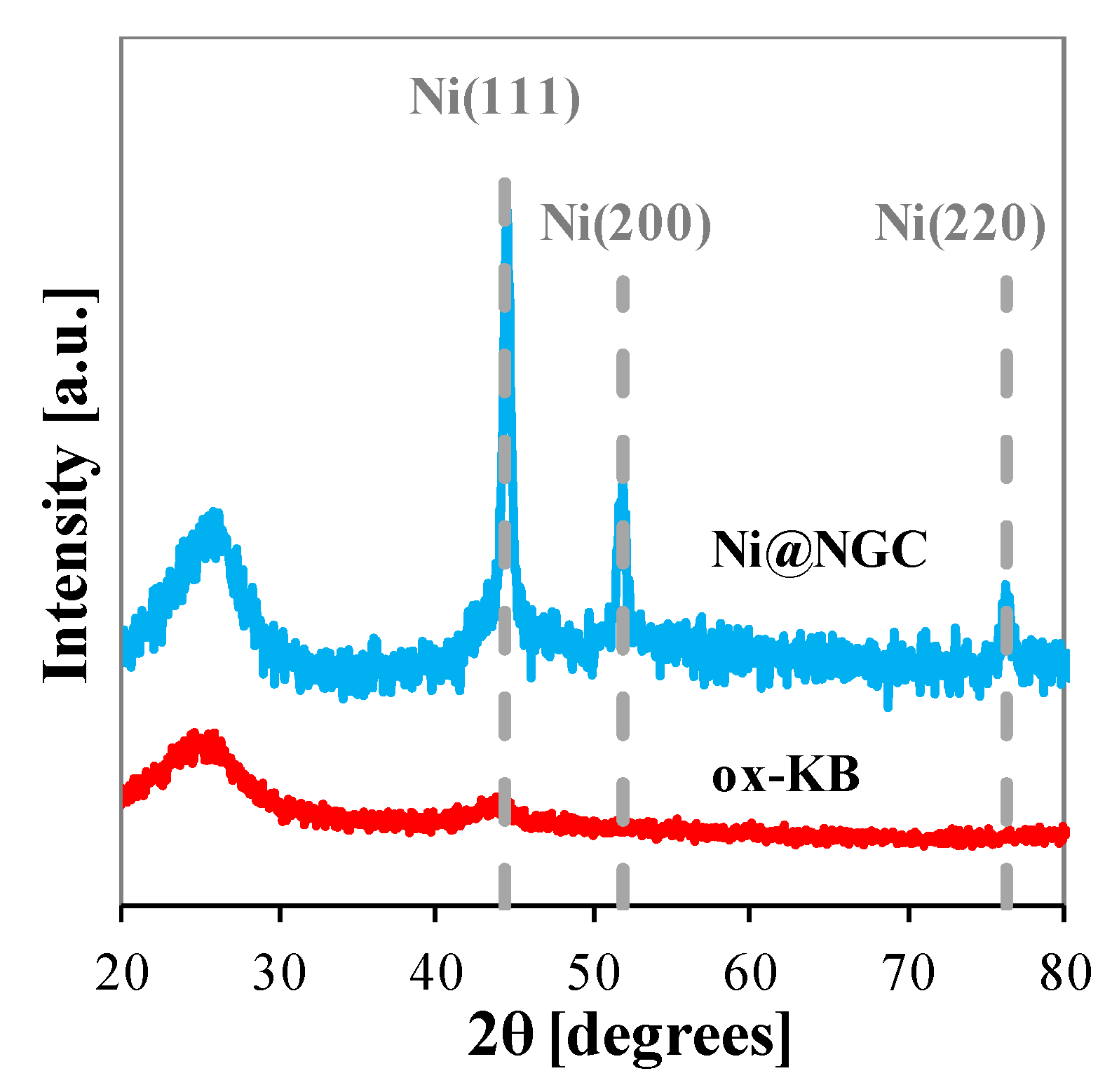
Figure 2 presents X-ray diffraction (XRD) patterns of the ox-KB and Ni@NGC. The broad characteristic diffraction peaks of (002) and (101) were found at ca. 25 and 42° for carbon species. The diffraction peak of Ni@NGC was sharper, shifted to the positive angle, and had increased intensity. For example, the diffraction peak of Ni@NGC at the C(002) plane showed 26° while the peak of ox-KB exhibited 25.2°, which indicates that Ni@NGC was highly graphitized in the carbon matrix [3,7]. It can be seen that Ni@NGC showed characteristic diffraction peaks at 44.5, 51.8, and 76.4°, which correspond to the (111), (200), and (220) planes of face-centered cubic (fcc) structure of Ni metal particle (JCPDS 04-0850), respectively. It showed that the Ni metal remained after acid-leaching at 80 °C. The particle size of Ni calculated by the Scherrer equation was 15.7, 13.5, and 14.2 nm based on (111), (200), and (220).
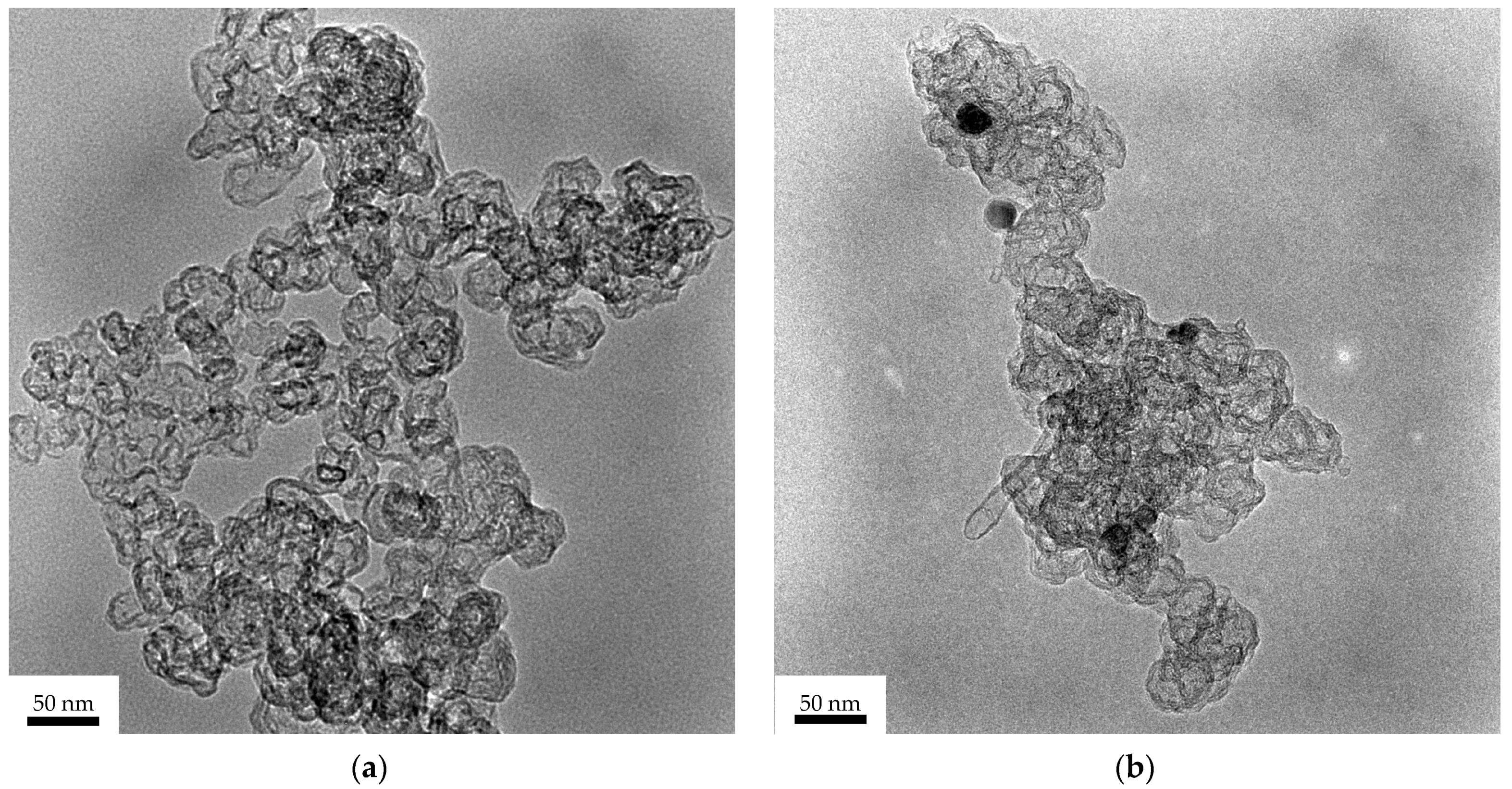
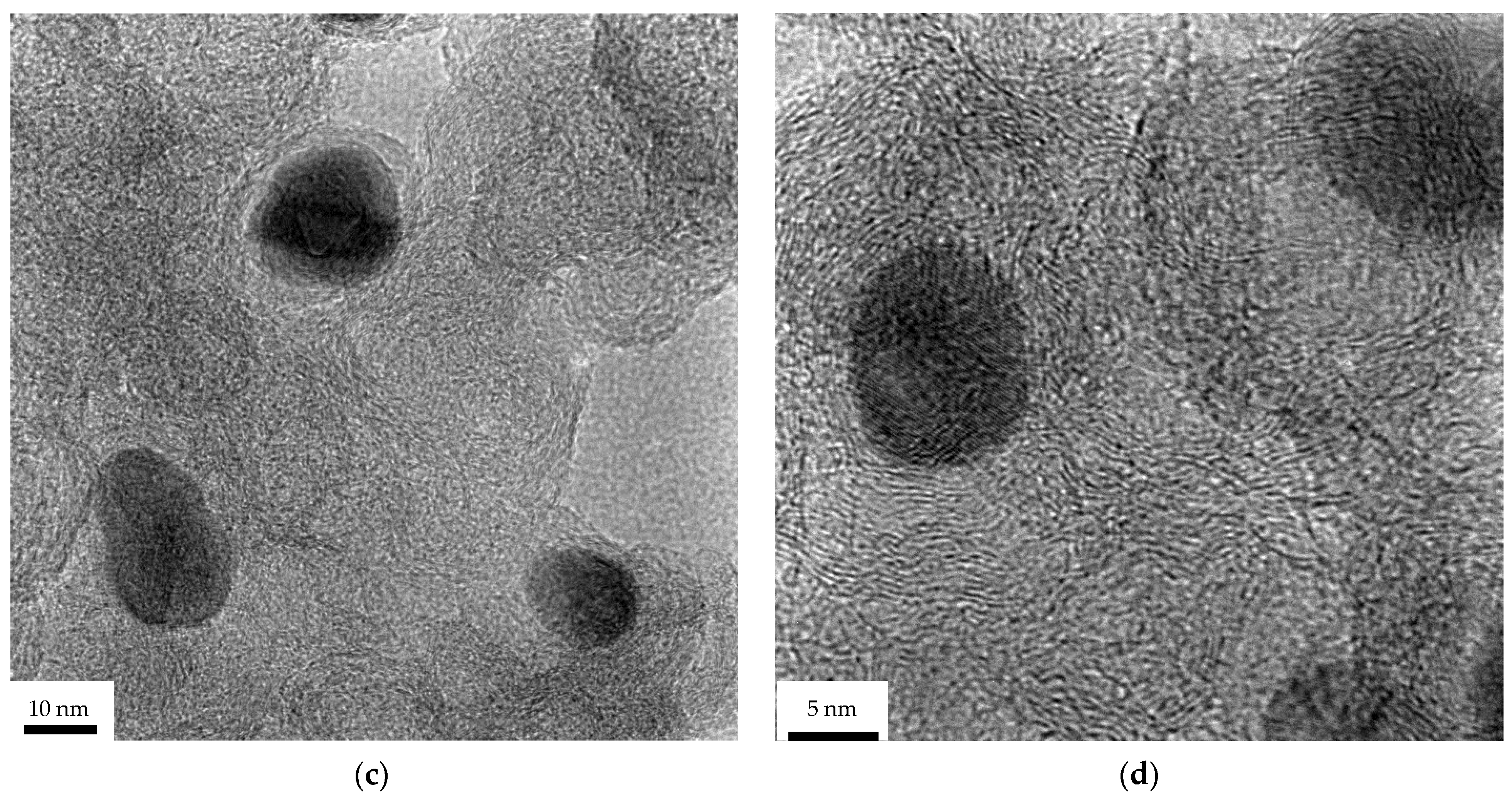
High resolution transmission electron microscope (HR-TEM) images for ox-KB and Ni@NGC are shown in Figure 3. Figure 3a showed ox-KB with an amorphous structure without any additional layer. As shown in Figure 3b, however, the ox-KB was covered with the graphitic carbon layer. The Ni particles encapsulated within the graphitic carbon layer in Figure 3b,c were observed in the carbon framework. Also, some carbon tubes could be seen since the Ni particles are efficient catalysts for the graphitization of carbon materials. This is the reason why the peaks corresponding to Ni after acid-leaching were observed in the XRD pattern of Ni@NGC in Figure 2.
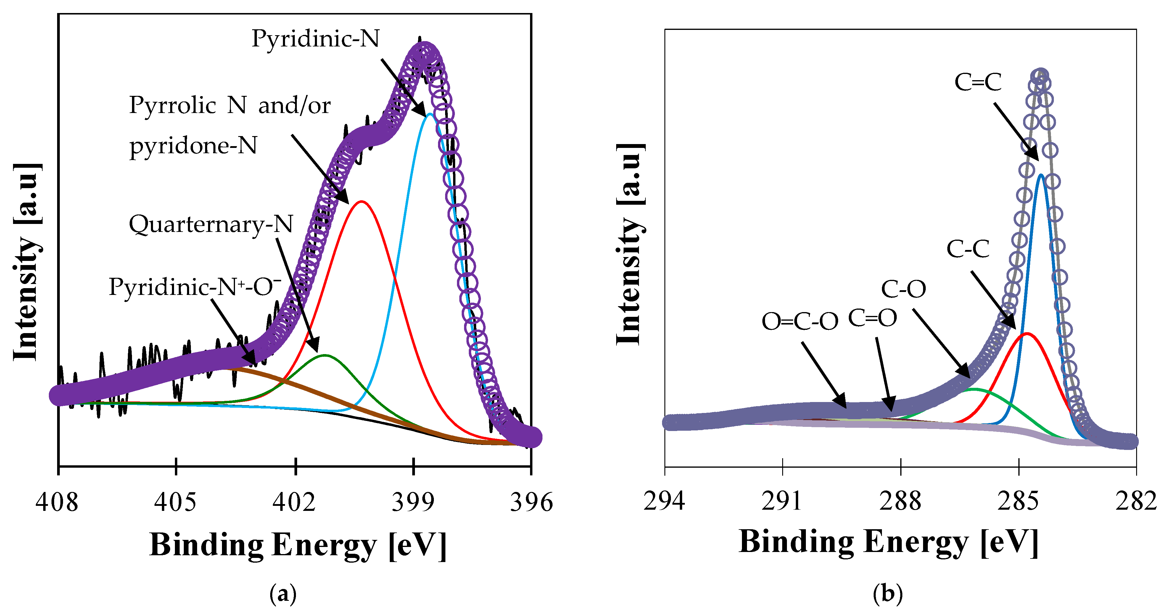
To further investigate the surface chemical analysis on Ni@NGC, X-ray photoelectron spectroscopy (XPS) analysis was employed. Figure 4 shows N 1s XPS spectra of Ni@NGC. N 1s XPS spectra were deconvoluted into four major components such as pyridinic, pyrrolic and/or pyridone, quarternary, and pyridinic-N+-O− (oxidized nitrogen) [11,26,27]. The peak at 396.6 eV accounts for the presence of pyridinic-N, whereas the peak at 400.4 eV corresponds to the pyrrolic-N and/or pyridine-N. Peaks at 401.1 and 403.5 eV are ascribed to the presence of quaternary-N and pyridinic-N+-O−, respectively. The concentrations of pyridinic-N and pyrrolic-N and/or pyridine-N were 42.8 and 39.5% of total nitrogen, respectively, which indicated that most nitrogen existed in two components. Quaternary-N accounted for 4.1% while pyridinic-N+-O− occupied 13.6%. According to the previous results [27], the composition of quaternary-N can vary with the activity of the catalyst for the graphitization. The low composition of quaternary-N could be obtained since Ni is not highly active for the graphitization and the temperature is not high enough to form the highly graphitized carbon. It is well-known that pyridinic-N located on the edge of the graphite planes improves the ORR by donating one p-electron to the aromatic π system since it is located on the edge of the graphite planes [3,28,29]. Moreover, the latest investigations showed that quaternary-N plays a role in stable ORR active sites [20,30]. In Figure 4b, C 1s XPS spectra were shown. The main peaks of C 1s at ca. 284.4 and 284.7 eV are ascribed to the sp2 C of C=C bonding and the sp3 C of C–C, while the peaks at ca. 286.1, 288.1, and 288.9 eV are attributed to the carbon atoms in the C–OH, C=O, and O–C=O functional groups, respectively.
2.2. Electrochemical Characterization of Ni@NGC
Figure 5 shows the cyclic voltammetry (CV) diagram of ox-KB and Ni@NGC. The measurements were performed in the nitrogen-saturated 0.1 M HClO4 at room temperature. The scan rate was 50 mV s−1. In comparison with the Ni@NGC, the ox-KB showed well-developed redox peaks at ca 0.64 and 0.50 V during the positive and negative scans, respectively. These characteristic peaks correspond to the reversible quinone-hydroquinone redox coupling [31,32,33,34], which means oxygen groups were properly introduced through the acid-oxidation. According to the literature, the carbon black treated by the nitric acid shows about 100 mV less activation overpotential for the ORR compared to the carbon black [17]. The reaction related to redox coupling can be explained as follows:
C=O + e− + H+ ↔ C-OH
In contrast to the ox-KB, the sharp peak at 0.50 and 0.65 V during the positive and negative scan, respectively, was not observed in the Ni@NGC. This is reasonable since the surface concentration of oxygen of Ni@NGC (1.7%) measured by XPS was even less than that of ox-KB (5.7%).
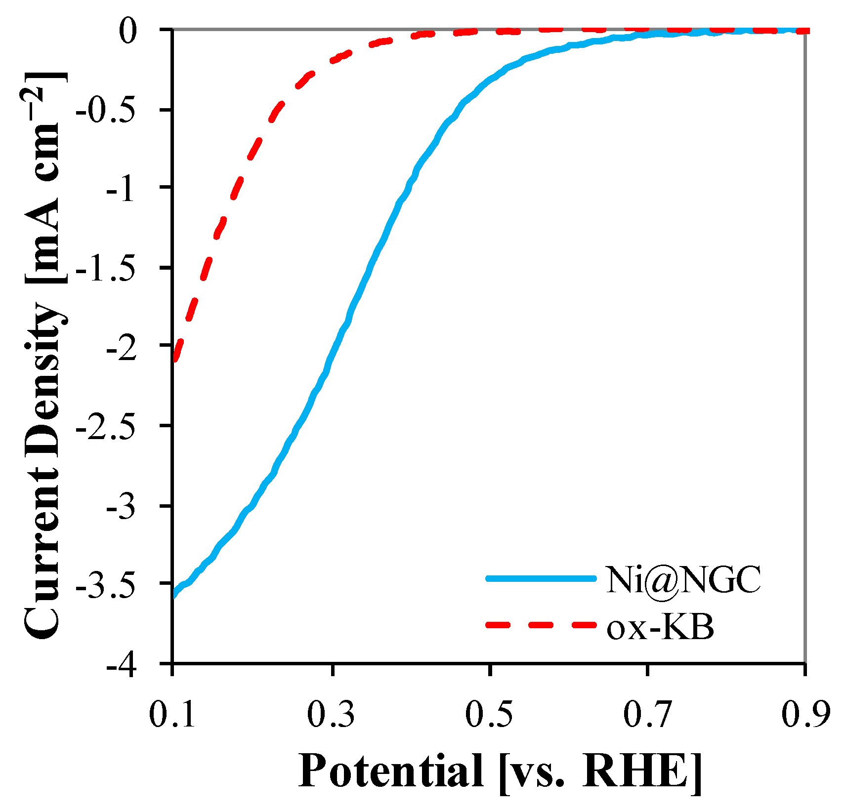
The Linear sweep voltammetry (LSV) diagrams of ox-KB and Ni@NGC are shown in Figure 6. LSV was performed in the oxygen-saturated 0.1 M HClO4 at room temperature at a scan rate of 5 mV s−1 and a rotation speed of 1600 rpm. It was observed that the onset potential on the Ni@NGC for the ORR, which shifts positively by about 0.3 V compared to the ox-KB, was ca. 0.74 V. Also, Ni@NGC showed better kinetic than ox-KB. For example, the current density at 0.5 V was 0.32 mA cm−2 for Ni@NGC while only 0.01 mA cm−2 was observed with ox-KB. The diffusion-limited plateau of the polarization curve for both carbon materials was not well-defined as was usually observed in the Pt catalysts. Jiang et al. showed that the plateau was inclined when the active sites on the catalyst were not evenly distributed and the reaction was not fast [35].
2.3. Physical Characterization of Pt/Ni@NGC
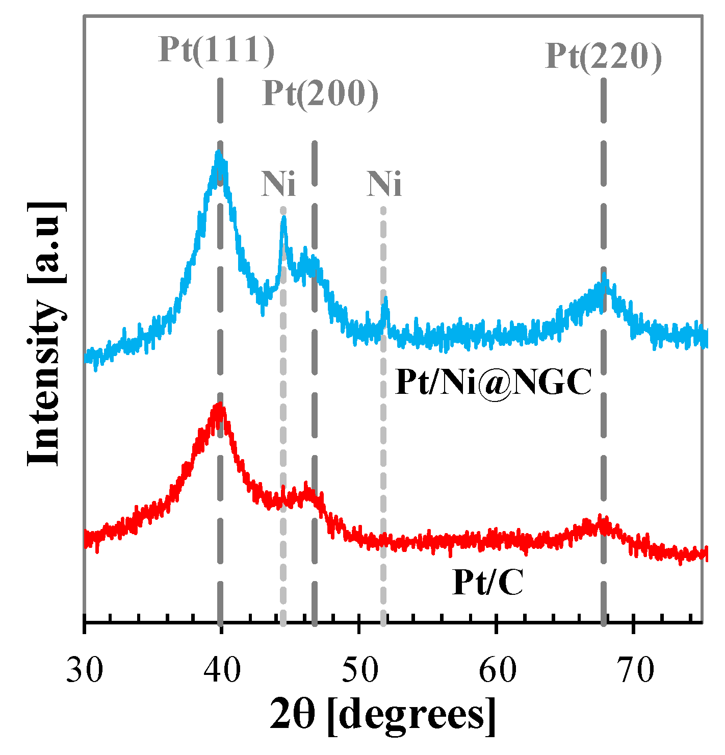
The XRD patterns of the Pt/Ni@NGC and Pt/C are shown in Figure 7. Both the supported Pt catalysts exhibited the characteristics of the Pt fcc structure. The characteristic diffraction peaks at 39.8, 46.7, 67.7, and 81.8° corresponded to the (111), (200), (220), and (311) planes of Pt nanoparticles, respectively, while those at 44.5, 51.8, and 76.4° were ascribed to (111), (200), and (220) planes of Ni nanoparticles, respectively, as shown in Figure 2. Based on Figure 2 and Figure 7, it was observed that the Pt/Ni@NGC did not form the alloy formation with existing Ni species. The Pt particle sizes, which were calculated using a Scherrer equation based on Pt (220) plane, were 2.4 nm and 2 nm for the Pt/Ni@NGC and Pt/C, respectively.
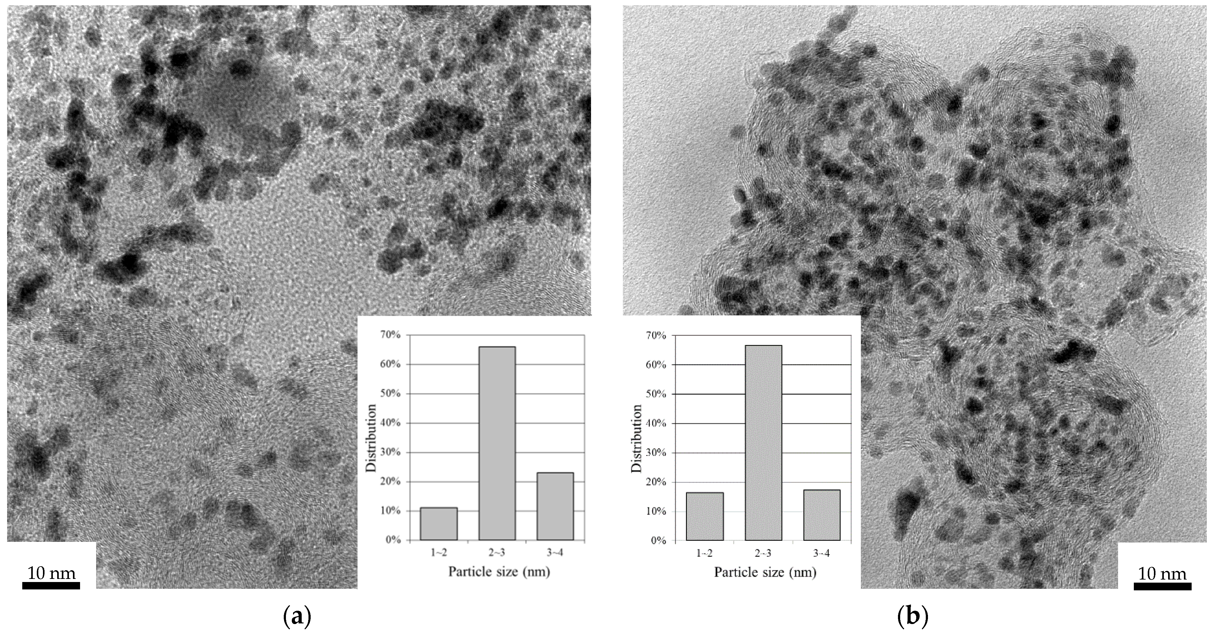
Figure 8 represents typical HR-TEM images of Pt/Ni@NGC and Pt/C catalysts. The HR-TEM image shown in Figure 8a reveals that the Pt nanoparticles prepared with the sodium formate as a reducing agent were successfully deposited on the Ni@NGC. The Pt nanoparticles were distributed evenly on the Ni@NGC with 2–3 nm of the mean particle size. The mean particle size observed in HR-TEM image of Pt/Ni@NGC was in good agreement with the result of XRD shown in Figure 7. Figure 8b is an HR-TEM image of Pt/C. The mean particle size of Pt/C was in the range of 2–3 nm.
2.4. Electrochemical Characterization and Performance
CV diagrams of Pt/Ni@NGC and Pt/C are presented in Figure 9. The experiments were achieved in the nitrogen-saturated 0.1 M HClO4 at room temperature using a three-electrode electrochemical cell. It was seen that the two redox reactions occurred on the Pt catalyst. One was hydrogen oxidation and reduction under ca. 0.4 V, while the other was oxygen oxidation and reduction on the Pt catalyst. Both catalysts showed the typical characteristic of polycrystalline Pt as shown in Figure 9. The ECSA in the CV diagrams was calculated from the hydrogen desorption region using the following equation:
wherein QH is hydrogen desorption charge in mC cm−2, and LPt is Pt loading in mgPt cm−2. The ECSA of Pt/C was 78.9 m2 g−1, while that of Pt/Ni@NGC showed 72.9 m2 g−1.
ECSA = 0.01QH/(210 µC cm−2Pt × LPt)
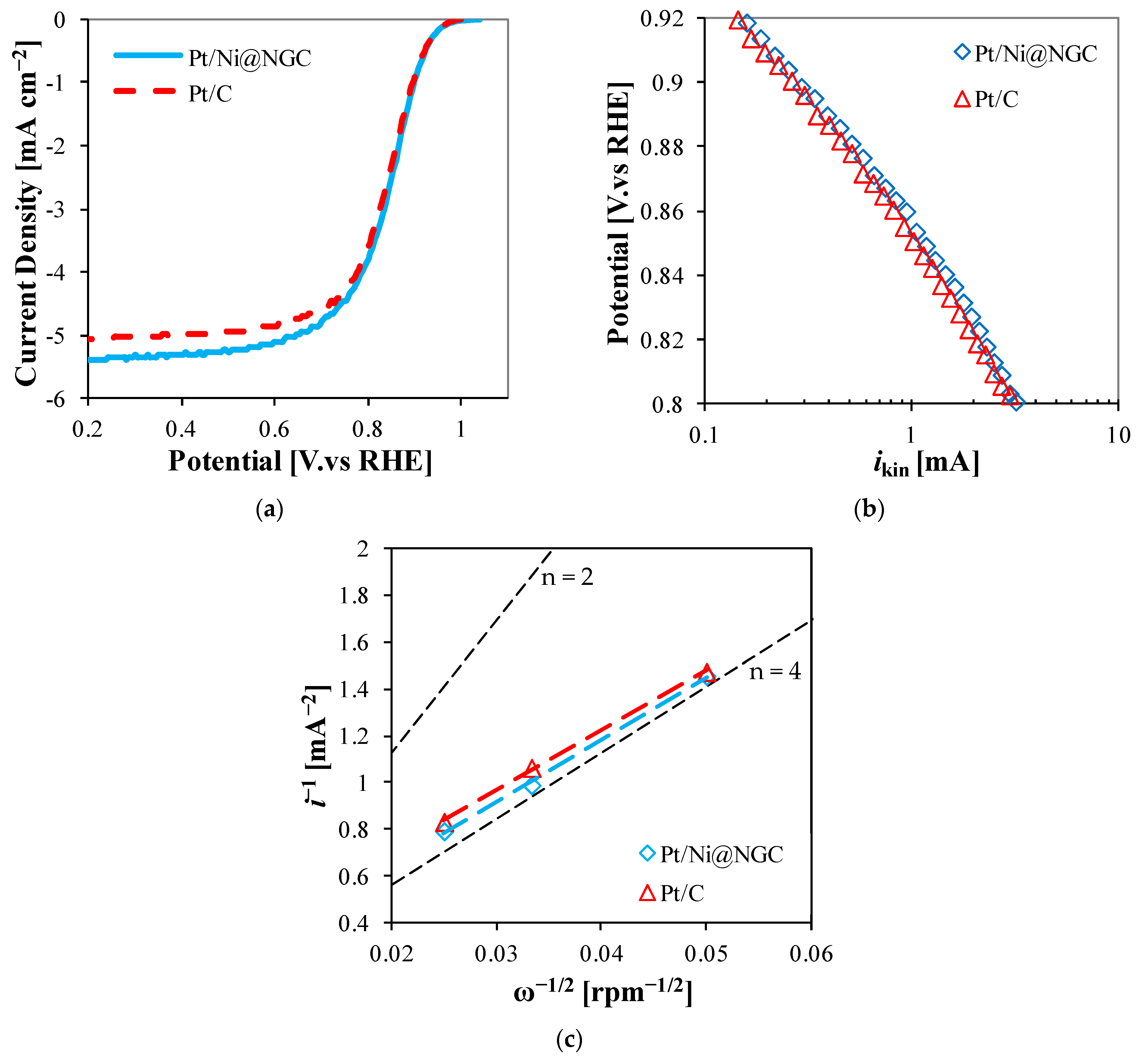
LSV diagrams of Pt/Ni@NGC and Pt/C are shown in Figure 10a. LSV was performed in the oxygen-saturated 0.1 M HClO4 at room temperature. The catalyst loading was 20 μgPt cm−2 for both catalysts. The diffusion-limited current of Pt/Ni@NGC was higher than that of Pt/C, while both Pt/Ni@NGC and Pt/C exhibited the identical on-set potential for ORR with ca. 1.0 V. The diffusion-limited current of Pt/Ni@NGC was observed as 5.34 mA cm−2 at 0.4 V whereas that of Pt/C showed 5.02 mA cm−2. Figure 10b shows ORR activities of Pt/Ni@NGC and Pt/C in the range from 0.80 to 0.92 V. To compare those activities, the activity plot was prepared using the following equation [36]:
where i is the measured current in LSV experiment, ik is the mass transport free kinetic current, and id is the diffusion-limited current. As shown in Figure 10b, Pt/Ni@NGC shows higher kinetic current than Pt/C. For example, at 0.85 V, the kinetic current of Pt/C was 1 mA, while that of Pt/Ni@NGC showed 1.2 mA. The Koutecky–Levich plots show a linear dependence as shown in Figure 10c. The linearity and the parallelism of these plots, in general, indicate first-order kinetics with respect to molecular oxygen [37]. Moreover, Pt/Ni@NGC shows to be more favorable to the four-electron pathway reaction over Pt/C.
1/i = 1/ik + 1/id
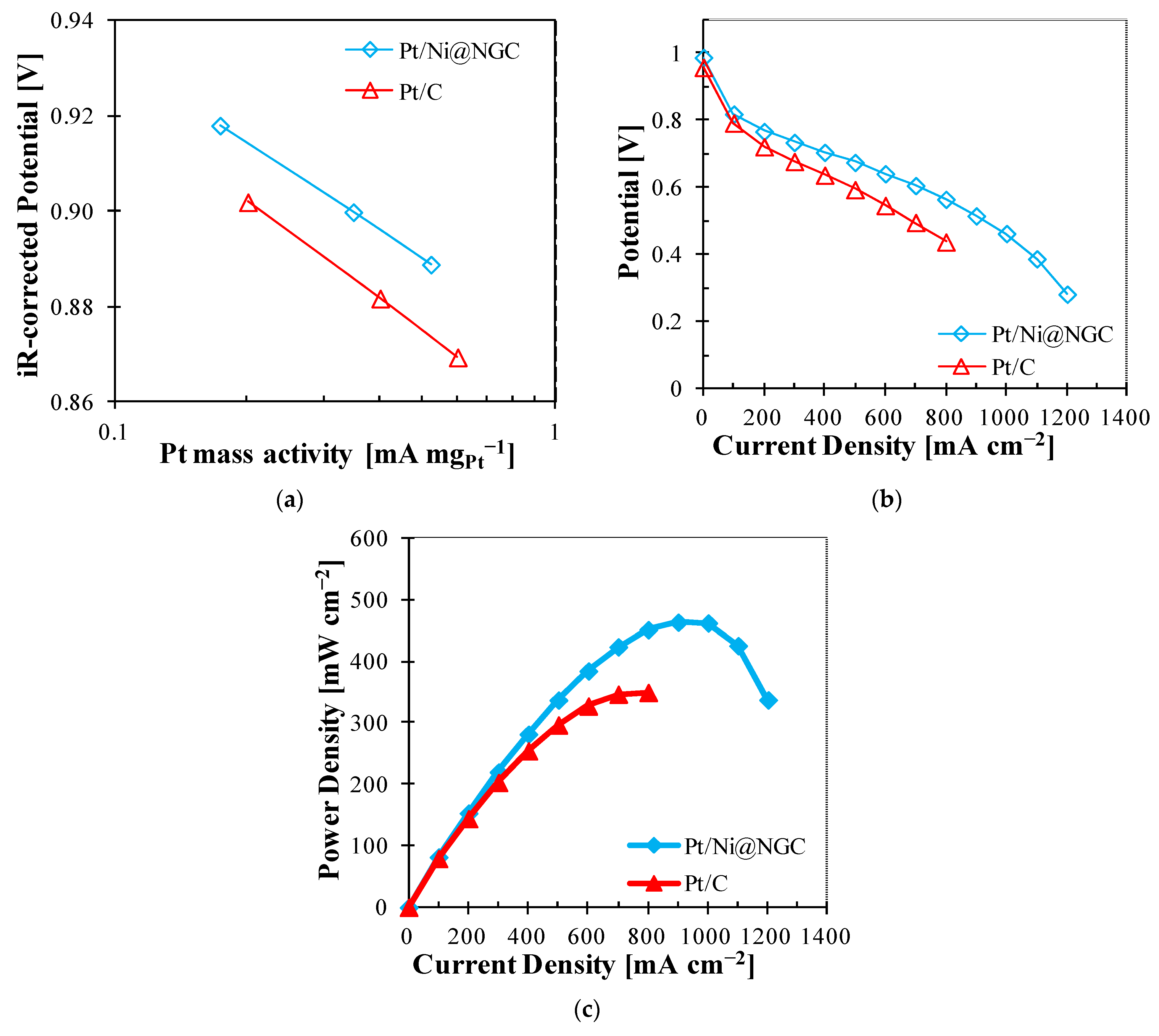
Figure 11a–c shows the cell polarization and power density curves obtained with Pt/Ni@NGC and Pt/C at 80 °C. Figure 11a shows the mass activity of catalysts supplying H2 and O2 to the anode and cathode at 100% relative humidity (RH). The mass activity of Pt/C at 0.9 ViR-corrected was 0.21 A mgPt−1, while Pt/Ni@NGC showed 0.35 A mgPt−1, which means the mass activity of Pt/Ni@NGC is enhanced by 66.7% compared to that of Pt/C. The improvement in the mass activity proves that the use of active Ni@NGC gives rise to the synergetic effect with Pt for the ORR at the cathode. Figure 11b,c shows the polarization curves and their corresponding power density curves under H2 and air atmosphere at a 40% RH. The membrane electrode assembly (MEA) with Pt/Ni@NGC as a cathode catalyst showed a maximum power density of 464 mW cm−2, while the MEA with Pt/C used in the cathode catalyst showed a maximum power density of 350 mW cm−2. At 800 mA cm−2, the potential of Pt/Ni@NGC exhibited 0.565 V and that of Pt/C showed 0.437 V. Furthermore, the open-circuit potential (OCP) of Pt/Ni@NGC was revealed at 0.988 V, which was even higher than that of Pt/C. The improved performance with Pt/Ni@NGC as a cathode catalyst can be attributed to the nitrogen-doped graphitic carbon layer containing pyridinic-N and quaternary-N components. As shown in Figure 6, Ni@NGC, which acts as a support, has activity toward the ORR. Its activity can be added to the activity of Pt for the ORR in the cathode. It has been reported that nitrogen doping results in disorder in graphene stacking. Such disorder structures and defects can play an important role in providing anchoring sites for the deposition of Pt nanoparticles [38,39,40,41]. Also, the performance can be enhanced due to the improved binding of carbon and catalyst and electrical conductivity by nitrogen doping [42,43]. Groves et al. showed that the more nitrogen atoms and the closer they are to the carbon atom bonding directly to the Pt particle, the stronger the binding energy using density functional theory (DFT) [44].
3. Materials and Methods
3.1. Preparation of Ni@NGC and Pt/Ni@NGC
The Ni@NGC was synthesized with a similar method as described elsewhere [20,26]. Briefly, first, commercially available carbon black (Ketjen Black EC-300J, Akzo Nobel, Amsterdam, The Netherlands) was oxidized with concentrated nitric acid. Two milliliters of ethylenediamine (EDA, Aldrich, St. Louis, MO, USA) and 0.5 g of Ni(NO3)2∙6H2O (Aldrich) as a nitrogen source and catalyst for the graphitization, respectively, were blended with ox-KB homogeneously in isopropyl alcohol (IPA, BDH). After reflux at 85 °C for 3 h, the solvent was removed by the rotary evaporator (Rotavapor® R-210, Buchi, New Castle, DE, USA). After fully dried, the powder was moved to the tubular furnace (OTF-1200X-SNT-110, MTI Corp., Richmond, VA, USA) to produce the N-doped graphitic carbon structure at 800 °C for 1 h under nitrogen atmosphere. Unstable metal species in the sample were removed with 0.5 M H2SO4 at 80 °C for 4 h. After filtering and washing with de-ionized (DI) water, the dried sample was utilized as a support of Pt catalyst.
Pt deposition was carried out using the electroless deposition method. The support was mixed with 0.02 M chloroplatinic acid hexahydrate (Alfa Aesar, Haverhill, MA, USA) in DI water. After mixing homogeneously, the solution was refluxed at 70 °C. 2 M sodium formate (Alfa Aesar, Haverhill, MA, USA) was added into the mixture slowly, followed by refluxing for 12 h. The resulting catalyst was washed with DI water and then fully dried at 80 °C. Consequently, 30% Pt/Ni@NGC was obtained.
3.2. Physical Characterization
The nitrogen adsorption/desorption isotherms were measured at −196 °C using a BET analyzer (Quantachrome NOVA 2000). Specific surface area for the sample was obtained by a multipoint Brunauer-Emmett–Teller (BET) analysis. XRD analysis was carried out using a Rigaku D/Max 2500 V/PC with a Cu Kα radiation (A tube voltage of 30 kV and a current of 15 mA).
XPS was performed with a Kratos AXIS 165 high-performance electron spectrometer to measure the elemental surface composition. HR-TEM was obtained by Hitachi 9500 HRTEM (300 kV accelerating voltage).
3.3. Electrochemical Characterization
Electrochemical characterization of the Ni@NGC and Pt/Ni@NGC was carried out in a rotating disk electrode (RDE) using a bi-potentiostat (Model AFCBP1, Pine Research Instrumentation, Durham, NC, USA). A glassy carbon disk electrode (0.247 cm2) functioned as a working electrode, while the platinum mesh and Ag/AgCl electrodes acted as counter and reference electrodes, respectively. RDE tests were operated in 0.1 M HClO4 electrolyte at ambient temperature. All potentials were reported against the reversible hydrogen electrode (RHE). Typically, for carbon species, 8 mg of carbon was ultrasonically dispersed in 1 mL of IPA. Fifteen microliters of the ink was dropped on the glassy carbon electrode. For the Pt catalyst experiment, the catalyst ink was made of Pt catalyst, absolute ethanol, and DI water ultrasonically. The catalyst ink was dropped onto the glassy carbon (catalyst loading: 20 μgPt cm−2). To provide good adhesion, 5 μL of 0.25 wt% ionomer (Alfa Aesar, Haverhill, MA, USA) was added onto the catalyst layer. CV was performed at a scan rate of 20 mV s−1 in a range of 0.005 V and 1.0 V purging with nitrogen. LSV was carried out at a scan rate of 5 mV s−1 in a range of 0.2 V and 1.05 V purging with oxygen. The LSV curves shown in this work were adequately corrected with the background capacitance current that was obtained in the nitrogen atmosphere at a scan rate of 5 mV s−1. For comparison purposes, the ox-KB and commercial Pt/C catalyst (TEC10EA50E, TKK, Tokyo, Japan) were evaluated at the same conditions.
3.4. MEA Fabrication and Single Cell Operation
For catalyst inks, a catalyst, IPA, ionomer, and DI water were ultrasonically mixed. The ionomer contents for the anode and cathode were 30% and 20%, respectively. To load 0.1 mgPt cm−2 for both the anode and cathode, the thus prepared catalyst inks were manually sprayed on the gas diffusion layer (Sigracet GDL 10BC, SGL, Wiesbaden, Germany). To confirm the catalyst loading, we employed X-ray fluorescence (XRF, Model XDAL, Fisher, Waltham, MA, USA). The commercial Pt/C catalyst was utilized as a catalyst for the anode. Both electrodes were pressed onto both sides of a polymer electrolyte membrane (Nafion-212, Dupont, Wilmington, NC, USA) at 140 °C under 20 kgf cm−2 for 3 min. The thus fabricated MEA was cooled to ambient temperature and assembled in 25 cm2 single cells. The single cell test was conducted using a fully automated test station (model 850e, Scribner Associates Inc., Southern Pines, NC, USA). The mass activity was obtained supplying 100% RH humidified H2 and O2 at the flow rates of 70 and 166 sccm, respectively. H2 and air humidified at 59 °C flowed to the anode and cathode inlets, respectively, to obtain polarization curves at the single cell temperature of 80 °C. Flow rates of H2 and air were controlled by the stoichiometric ratios of 1.5 and 1.8, respectively, under backpressure of 150 kPaabs. Below 0.2 A cm−2, equivalent flows at 0.2 A cm−2 were supplied to both sides. For comparison purposes, MEA with the commercial Pt/C catalyst as a cathode was also fabricated and measured at the same conditions.
4. Conclusions
In this study, Ni@NGC was prepared with a facile approach and employed as a support of cathode catalyst in PEMFCs. Ni@NGC showed mesoporous characteristics and a large surface area with the graphitized carbon structure containing the nitrogen. Chelated-EDA was converted to the N-doped graphitic carbon layer, which involved pyrrolic and/or pyridone, pyridinic, quarternary, and pyridinic-N+-O−. pyridinic and/or quaterary-N. After these groups were doped in the carbon structure, the activity for the ORR was significantly enhanced. Also, we deposited Pt on the active Ni@NGC as a support, instead of conventional carbon black. According to HR-TEM and XRD, Pt particles were evenly deposited on the surface of Ni@NGC. RDE showed that Pt/Ni@NGC was more active and reduced the oxygen via a more effective four-electron pathway than the commercial Pt/C. Based on these beneficial properties of Pt/Ni@NGC, in the fuel cell test, the mass activity of Pt/Ni@NGC showed to be over 1.5 times higher than that of commercial Pt/C. As well, the maximum power density of Pt/Ni@NGC was 464 mW cm−2, while that of Pt/C showed 350 mW cm−2.
Funding
This work was supported by U.S. Department of Energy (No. DE-EE0000460) and the National Research Foundation of Korea (NRF) grant funded by the Korea government (MSIT) (No. 2020R1C1C1004206).
Acknowledgments
The authors gratefully acknowledge the financial support received from U.S. Department of Energy and the National Research Foundation of Korea.
Conflicts of Interest
The author declares no conflict of interest.
References
- Liu, B.; Bard, A.J. Scanning Electrochemical Microscopy. 45. Study of the Kinetics of Oxygen Reduction on Platinum with Potential Programming of the Tip. J. Phys. Chem. B 2002, 106, 12801–12806. [Google Scholar] [CrossRef]
- Song, C.; Zhang, J. Electrocatalytic oxygen reduction reaction. In PEM Fuel Cell Electrocatalyst: Fundamentals and Applications; Zhang, J., Ed.; Springer: London, UK, 2008; pp. 89–134. [Google Scholar]
- Shao, Y.; Sui, J.; Yin, G.; Gao, Y. Nitrogen-doped carbon nanostructures and their composites as catalytic materials for proton exchange membrane fuel cell. Appl. Catal. B Environ. 2008, 79, 89–99. [Google Scholar] [CrossRef]
- Chen, Y.; Wang, J.; Liu, H.; Li, R.; Sun, X.; Ye, S.; Knights, S. Enhanced stability of Pt electrocatalysts by nitrogen doping in CNTs for PEM fuel cells. Electrochem. Commun. 2009, 11, 2071–2076. [Google Scholar] [CrossRef]
- Lepró, X.; Terrés, E.; Vega-Cantú, Y.; Rodríguez-Macías, F.J.; Muramatsu, H.; Kim, Y.A.; Hayahsi, T.; Endo, M.; Torres, R.M.; Terrones, M. Efficient anchorage of Pt clusters on N-doped carbon nanotubes and their catalytic activity. Chem. Phys. Lett. 2008, 463, 124–129. [Google Scholar] [CrossRef]
- Wang, B. Recent development of non-platinum catalysts for oxygen reduction reaction. J. Power Sources 2005, 152, 1–15. [Google Scholar] [CrossRef]
- Nallathambi, V.; Lee, J.-W.; Kumaraguru, S.P.; Wu, G.; Popov, B.N. Development of high performance carbon composite catalyst for oxygen reduction reaction in PEM Proton Exchange Membrane fuel cells. J. Power Sources 2008, 183, 34–42. [Google Scholar] [CrossRef]
- Deshmukh, A.A.; Ul Islam, R.; Witcomb, M.J.; van Otterlo, W.A.L.; Coville, N.J. Catalytic Activity of Metal Nanoparticles Supported on Nitrogen-Doped Carbon Spheres. ChemCatChem 2010, 2, 51–54. [Google Scholar] [CrossRef]
- Higgins, D.C.; Meza, D.; Chen, Z. Nitrogen-Doped Carbon Nanotubes as Platinum Catalyst Supports for Oxygen Reduction Reaction in Proton Exchange Membrane Fuel Cells. J. Phys. Chem. C 2010, 114, 21982–21988. [Google Scholar] [CrossRef]
- Wang, X.; Yang, S.; Yu, Y.; Dou, M.; Zhang, Z.; Wang, F. Low-loading Pt nanoparticles embedded on Ni, N-doped carbon as superior electrocatalysts for oxygen reduction. Catal. Sci. Technol. 2020, 10, 65–69. [Google Scholar] [CrossRef]
- Jung, W.S.; Popov, B.N. Hybrid cathode catalyst with synergistic effect between carbon composite catalyst and Pt for ultra-low Pt loading in PEMFCs. Catal. Today 2017, 295, 65–74. [Google Scholar] [CrossRef]
- Karuppanan, K.K.; Raghu, A.V.; Panthalingal, M.K.; Ramanathan, S.; Kumaresan, T.; Pullithadathil, B. Triple phase boundary augmentation in hierarchical, Pt grafted N-doped mesoporous carbon nanofibers for high performance and durable PEM fuel cells. J. Mater. Chem. A 2018, 6, 12768–12781. [Google Scholar] [CrossRef]
- Park, J.-Y.; Kwak, D.-H.; Ma, K.-B.; Han, S.-B.; Chai, G.S.; Kim, S.-K.; Peck, D.-H.; Kim, C.-S.; Kucernak, A.; Park, K.-W. Enhanced oxygen reduction reaction of Pt deposited Fe/N-doped bimodal porous carbon nanostructure catalysts. J. Catal. 2018, 359, 46–54. [Google Scholar] [CrossRef]
- Yang, H.; Ko, Y.; Lee, W.; Züttel, A.; Kim, W. Nitrogen-doped carbon black supported Pt–M (M = Pd, Fe, Ni) alloy catalysts for oxygen reduction reaction in proton exchange membrane fuel cell. Mater. Today Energy 2019, 13, 374–381. [Google Scholar] [CrossRef]
- Rethinasabapathy, M.; Kang, S.-M.; Haldorai, Y.; Jonna, N.; Jankiraman, M.; Lee, G.-W.; Jang, S.-C.; Natesan, B.; Roh, C.; Huh, Y.S. Quaternary PtRuFeCo nanoparticles supported N-doped graphene as an efficient bifunctional electrocatalyst for low-temperature fuel cells. J. Ind. Eng. Chem. 2019, 69, 285–294. [Google Scholar] [CrossRef]
- Tian, Y.; Liu, Y.-J.; Zhao, J.-X.; Ding, Y.-H. High stability and superior catalytic reactivity of nitrogen-doped graphene supporting Pt nanoparticles as a catalyst for the oxygen reduction reaction: A density functional theory study. RSC Adv. 2015, 5, 34070–34077. [Google Scholar] [CrossRef]
- Subramanian, N.P.; Kumaraguru, S.P.; Colon-Mercado, H.; Kim, H.; Popov, B.N.; Black, T.; Chen, D.A. Studies on Co-based catalysts supported on modified carbon substrates for PEMFC cathodes. J. Power Sources 2006, 157, 56–63. [Google Scholar] [CrossRef]
- Liu, G.; Li, X.; Ganesan, P.; Popov, B.N. Development of non-precious metal oxygen-reduction catalysts for PEM fuel cells based on N-doped ordered porous carbon. Appl. Catal. B Environ. 2009, 93, 156–165. [Google Scholar] [CrossRef]
- Li, X.; Liu, G.; Popov, B.N. Activity and stability of non-precious metal catalysts for oxygen reduction in acid and alkaline electrolytes. J. Power Sources 2010, 195, 6373–6378. [Google Scholar] [CrossRef]
- Liu, G.; Li, X.; Ganesan, P.; Popov, B.N. Studies of oxygen reduction reaction active sites and stability of nitrogen-modified carbon composite catalysts for PEM fuel cells. Electrochim. Acta 2010, 55, 2853–2858. [Google Scholar] [CrossRef]
- Li, X.; Park, S.; Popov, B.N. Highly stable Pt and PtPd hybrid catalysts supported on a nitrogen-modified carbon composite for fuel cell application. J. Power Sources 2010, 195, 445–452. [Google Scholar] [CrossRef]
- Popov, B.N.; Li, X.; Liu, G.; Lee, J.-W. Power source research at USC: Development of advanced electrocatalysts for polymer electrolyte membrane fuel cells. Int. J. Hydrog. Energy 2011, 36, 1794–1802. [Google Scholar] [CrossRef]
- Subramanian, N.P.; Li, X.; Nallathambi, V.; Kumaraguru, S.P.; Colon-Mercado, H.; Wu, G.; Lee, J.-W.; Popov, B.N. Nitrogen-modified carbon-based catalysts for oxygen reduction reaction in polymer electrolyte membrane fuel cells. J. Power Sources 2009, 188, 38–44. [Google Scholar] [CrossRef]
- Zhai, Y.; Dou, Y.; Zhao, D.; Fulvio, P.F.; Mayes, R.T.; Dai, S. Carbon Materials for Chemical Capacitive Energy Storage. Adv. Mater. 2011, 23, 4828–4850. [Google Scholar] [CrossRef]
- Su, F.; Zeng, J.; Bao, X.; Yu, Y.; Lee, J.Y.; Zhao, X.S. Preparation and Characterization of Highly Ordered Graphitic Mesoporous Carbon as a Pt Catalyst Support for Direct Methanol Fuel Cells. Chem. Mater. 2005, 17, 3960–3967. [Google Scholar] [CrossRef]
- Jung, W.S. High-performance bimetallic alloy catalyst using Ni and N co-doped composite carbon for the oxygen electro-reduction. J. Colloid Interface Sci. 2018, 514, 30–39. [Google Scholar] [CrossRef]
- Jung, W.S.; Popov, B.N. Improved durability of Pt catalyst supported on N-doped mesoporous graphitized carbon for oxygen reduction reaction in polymer electrolyte membrane fuel cells. Carbon 2017, 122, 746–755. [Google Scholar] [CrossRef]
- Wong, W.Y.; Daud, W.R.W.; Mohamad, A.B.; Kadhum, A.A.H.; Majlan, E.H.; Loh, K.S. Nitrogen-containing carbon nanotubes as cathodic catalysts for proton exchange membrane fuel cells. Diam. Relat. Mater. 2012, 22, 12–22. [Google Scholar] [CrossRef]
- Matter, P.H.; Zhang, L.; Ozkan, U.S. The role of nanostructure in nitrogen-containing carbon catalysts for the oxygen reduction reaction. J. Catal. 2006, 239, 83–96. [Google Scholar] [CrossRef]
- Niwa, H.; Horiba, K.; Harada, Y.; Oshima, M.; Ikeda, T.; Terakura, K.; Ozaki, J.-I.; Miyata, S. X-ray absorption analysis of nitrogen contribution to oxygen reduction reaction in carbon alloy cathode catalysts for polymer electrolyte fuel cells. J. Power Sources 2009, 187, 93–97. [Google Scholar] [CrossRef]
- Kangasniemi, K.H.; Condit, D.A.; Jarvi, T.D. Characterization of Vulcan Electrochemically Oxidized under Simulated PEM Fuel Cell Conditions. J. Electrochem. Soc. 2004, 151, E125–E132. [Google Scholar] [CrossRef]
- Ye, J.-S.; Liu, X.; Cui, H.F.; Zhang, W.-D.; Sheu, F.-S.; Lim, T.M. Electrochemical oxidation of multi-walled carbon nanotubes and its application to electrochemical double layer capacitors. Electrochem. Commun. 2005, 7, 249–255. [Google Scholar] [CrossRef]
- Wang, J.; Yin, G.; Shao, Y.; Zhang, S.; Wang, Z.; Gao, Y. Effect of carbon black support corrosion on the durability of Pt/C catalyst. J. Power Sources 2007, 171, 331–339. [Google Scholar] [CrossRef]
- Chen, J.H.; Li, W.Z.; Wang, D.Z.; Yang, S.X.; Wen, J.G.; Ren, Z.F. Electrochemical characterization of carbon nanotubes as electrode in electrochemical double-layer capacitors. Carbon 2002, 40, 1193–1197. [Google Scholar] [CrossRef]
- Jiang, R.; Anson, F.C. The origin of inclined plateau currents in steady-state voltammograms for electrode processes involving electrocatalysis. J. Electroanal. Chem. Interf. Electrochem. 1991, 305, 171–184. [Google Scholar] [CrossRef]
- Gojković, S.L.; Zečević, S.K.; Savinell, R.F. O2 Reduction on an Ink-Type Rotating Disk Electrode Using Pt Supported on High-Area Carbons. J. Electrochem. Soc. 1998, 145, 3713–3720. [Google Scholar] [CrossRef]
- Zhang, J.; Mo, Y.; Vukmirovic, M.B.; Klie, R.; Sasaki, K.; Adzic, R.R. Platinum Monolayer Electrocatalysts for O2 Reduction: Pt Monolayer on Pd(111) and on Carbon-Supported Pd Nanoparticles. J. Phys. Chem. B 2004, 108, 10955–10964. [Google Scholar] [CrossRef]
- Wang, C.H.; Du, H.Y.; Tsai, Y.T.; Chen, C.P.; Huang, C.J.; Chen, L.C.; Chen, K.H.; Shih, H.C. High performance of low electrocatalysts loading on CNT directly grown on carbon cloth for DMFC. J. Power Sources 2007, 171, 55–62. [Google Scholar] [CrossRef]
- Sjöström, H.; Stafström, S.; Boman, M.; Sundgren, J.E. Superhard and Elastic Carbon Nitride Thin Films Having Fullerenelike Microstructure. Phys. Rev. Lett. 1995, 75, 1336–1339. [Google Scholar] [CrossRef]
- Jia, R.L.; Wang, C.Y.; Wang, S.M. Preparation of carbon supported platinum catalysts: Role of π sites on carbon support surface. J. Mater. Sci. 2006, 41, 6881–6888. [Google Scholar] [CrossRef]
- Jafri, R.I.; Rajalakshmi, N.; Ramaprabhu, S. Nitrogen doped graphene nanoplatelets as catalyst support for oxygen reduction reaction in proton exchange membrane fuel cell. J. Mater. Chem. 2010, 20, 7114–7117. [Google Scholar] [CrossRef]
- Ma, Y.; Zhang, C.; Ji, G.; Lee, J.Y. Nitrogen-doped carbon-encapsulation of Fe3O4 for increased reversibility in Li+ storage by the conversion reaction. J. Mater. Chem. 2012, 22, 7845–7850. [Google Scholar] [CrossRef]
- Fujisawa, K.; Tojo, T.; Muramatsu, H.; Elías, A.L.; Vega-Díaz, S.M.; Tristán-López, F.; Kim, J.H.; Hayashi, T.; Kim, Y.A.; Endo, M.; et al. Enhanced electrical conductivities of N-doped carbon nanotubes by controlled heat treatment. Nanoscale 2011, 3, 4359–4364. [Google Scholar] [CrossRef] [PubMed] [Green Version]
- Groves, M.N.; Chan, A.S.W.; Malardier-Jugroot, C.; Jugroot, M. Improving platinum catalyst binding energy to graphene through nitrogen doping. Chem. Phys. Lett. 2009, 481, 214–219. [Google Scholar] [CrossRef]
Figure 1.
(a) N2 adsorption–desorption isotherms; (b) BJH pore-size distribution plots of Ni@NGC and ox-KB. The inset in (b) shows the pore size distribution in the range 0–10 nm.
Figure 1.
(a) N2 adsorption–desorption isotherms; (b) BJH pore-size distribution plots of Ni@NGC and ox-KB. The inset in (b) shows the pore size distribution in the range 0–10 nm.

Figure 2.
XRD patterns of the Ni@NGC and ox-KB.

Figure 3.
HR-TEM images of (a) ox-KB and (b–d) Ni@NGC.


Figure 4.
(a) N 1s and (b) C 1s XPS spectra of the Ni@NGC.

Figure 5.
CV diagrams of ox-KB and Ni@NGC in nitrogen-saturated 0.1 M HClO4 at a scan rate of 50 mV s−1 at room temperature.
Figure 5.
CV diagrams of ox-KB and Ni@NGC in nitrogen-saturated 0.1 M HClO4 at a scan rate of 50 mV s−1 at room temperature.

Figure 6.
LSV curves of ox-KB and Ni@NGC in oxygen-saturated 0.1 M HClO4 with a scan rate of 5 mV s−1 and a rotation speed of 1600 rpm at room temperature.
Figure 6.
LSV curves of ox-KB and Ni@NGC in oxygen-saturated 0.1 M HClO4 with a scan rate of 5 mV s−1 and a rotation speed of 1600 rpm at room temperature.

Figure 7.
XRD patterns of the Pt/Ni@NGC and Pt/C.

Figure 8.
HR-TEM images of (a) Pt/Ni@NGC and (b) Pt/C.

Figure 9.
CV diagrams of Pt/Ni@NGC and Pt/C in nitrogen-saturated 0.1 M HClO4 with a scan rate of 50 mV s−1 at room temperature.
Figure 9.
CV diagrams of Pt/Ni@NGC and Pt/C in nitrogen-saturated 0.1 M HClO4 with a scan rate of 50 mV s−1 at room temperature.

Figure 10.
(a) LSV curves of Pt/Ni@NGC and Pt/C in oxygen-saturated 0.1 M HClO4 with a scan rate of 5 mV s−1 and a rotation speed of 1600 rpm at room temperature. (b) Activities of Pt/Ni@NGC and Pt/C obtained from (a). (c) Koutechy-Levich plot of Pt/Ni@NGC and Pt/C.
Figure 10.
(a) LSV curves of Pt/Ni@NGC and Pt/C in oxygen-saturated 0.1 M HClO4 with a scan rate of 5 mV s−1 and a rotation speed of 1600 rpm at room temperature. (b) Activities of Pt/Ni@NGC and Pt/C obtained from (a). (c) Koutechy-Levich plot of Pt/Ni@NGC and Pt/C.

Figure 11.
(a) Potential curves of Pt/Ni@NGC and Pt/C as a function of mass activity. H2 and O2 were fed to the anode and cathode at 70 sccm and 166 sccm, respectively, at 80 °C with 100% RH applying backpressure of 150 kPaabs. (b) Polarization curves and (c) power density curves of Pt/Ni@NGC and Pt/C. H2 and air were fed to the anode and cathode at a stoichiometric ratio of 1.5 and 1.8, respectively, applying backpressure of 150 kPaabs at 80 °C with 40% RH. Below 0.2 A cm−2, equivalent flows at 0.2 A cm−2 were supplied to both sides.

Publisher’s Note: MDPI stays neutral with regard to jurisdictional claims in published maps and institutional affiliations. |
© 2021 by the author. Licensee MDPI, Basel, Switzerland. This article is an open access article distributed under the terms and conditions of the Creative Commons Attribution (CC BY) license (https://creativecommons.org/licenses/by/4.0/).
Share and Cite
MDPI and ACS Style
Jung, W.S. Enhanced Performance of Pt Nanoparticles on Ni-N Co-Doped Graphitized Carbon for Oxygen Reduction Reaction in Polymer Electrolyte Membrane Fuel Cells. Catalysts 2021, 11, 909. https://0-doi-org.brum.beds.ac.uk/10.3390/catal11080909
AMA Style
Jung WS. Enhanced Performance of Pt Nanoparticles on Ni-N Co-Doped Graphitized Carbon for Oxygen Reduction Reaction in Polymer Electrolyte Membrane Fuel Cells. Catalysts. 2021; 11(8):909. https://0-doi-org.brum.beds.ac.uk/10.3390/catal11080909
Chicago/Turabian StyleJung, Won Suk. 2021. "Enhanced Performance of Pt Nanoparticles on Ni-N Co-Doped Graphitized Carbon for Oxygen Reduction Reaction in Polymer Electrolyte Membrane Fuel Cells" Catalysts 11, no. 8: 909. https://0-doi-org.brum.beds.ac.uk/10.3390/catal11080909
Note that from the first issue of 2016, this journal uses article numbers instead of page numbers. See further details here.