Article

Indigo-Mediated Semi-Microbial Biofuel Cell Using an Indigo-Dye Fermenting Suspension

1
Division of Applied Life Sciences, Graduate School of Agriculture, Kyoto University, Kitashirakawa Oiwake-cho, Sakyo-ku, Kyoto 606-8502, Japan
2
Graduate School of Advanced Technology and Science, Tokushima University, 2-1 Minamijosanjima-cho, Tokushima 770-8513, Japan
3
Center for Advanced Science and Innovation, Kyoto University, Gokasho, Uji, Kyoto 611-0011, Japan
4
Industrial Microbiology, Graduate School of Agriculture, Kyoto University, Kitashirakawa Oiwake-cho, Sakyo-ku, Kyoto 606-8502, Japan
5
Graduate School of Technology, Industrial and Social Sciences, Tokushima University, 2-1 Minamijosanjima-cho, Tokushima 770-8513, Japan
*
Authors to whom correspondence should be addressed.
These authors contributed equally as first authors.
Submission received: 16 July 2021 / Revised: 5 September 2021 / Accepted: 6 September 2021 / Published: 8 September 2021

Abstract

:
Aizome (Japanese indigo dyeing) is a unique dyeing method using microbial activity under anaerobic alkaline conditions. In indigo-dye fermenting suspensions; microorganisms reduce indigo into leuco-indigo with acetaldehyde as a reductant. In this study; we constructed a semi-microbial biofuel cell using an indigo-dye fermenting suspension. Carbon fiber and Pt mesh were used as the anode and cathode materials, respectively. The open-circuit voltage (OCV) was 0.6 V, and the maximum output power was 32 µW cm−2 (320 mW m−2). In addition, the continuous stability was evaluated under given conditions starting with the highest power density; the power density rapidly decreased in 0.5 h due to the degradation of the anode. Conversely, at the OCV, the anode potential exhibited high stability for two days. However, the OCV decreased by approximately 80 mV after 2 d compared with the initial value, which was attributed to the performance degradation of the gas-diffusion-cathode system caused by the evaporation of the dispersion solution. This is the first study to construct a semi-microbial biofuel cell using an indigo-dye fermenting suspension.

Graphical Abstract

1. Introduction

Microbial fuel cells (MBFCs) generate electricity using organic compounds, such as glucose [1,2,3,4], lactate [3,5,6,7,8], acetate [3], and ethanol [9], via microbial activity [10]. Mediated electron-transfer (MET)-type MBFCs are major MBFCs. To improve the electron-transfer process, artificial redox mediators are usually added to an anolyte of an MBFC, e.g., 9,10-anthraquinone-2,6-disulfonic acid disodium, safranine O, resazurin, methylene blue, and humic acid [11]. For example, the addition of 2-hydroxy-1,4-naphthoquinone can construct MBFC using Escherichia coli [2].
Shewanella oneidensis [5,6,7,8] and Pseudomonas aeruginosa [12] can produce a redox mediator, which enables the construction of MET-type MBFCs without adding artificial redox mediators. Shewanella strains and P. aeruginosa secrete a flavin mononucleotide (FMN) [13,14] and phenazine derivatives [15], respectively. In contrast, Rhodoferax ferrireducens [4] and Geobacter sulfurreducens [16,17] can construct mediatorless MBFCs, which are called direct electron-transfer (DET)-type MBFCs. R. ferrireducens and G. sulfurreducens are Fe(III)-reducing microorganisms, and they grow on Fe(III) as electron acceptors. G. sulfurreducens reduce Fe(III) oxide via nanowire [16], which may transfer electrons directly to the electrode.
In general, an MBFC is constructed with the aforementioned microbial anode and a dioxygen (O2)-reducing cathode, and it works under a neutral pH condition. Multicopper oxidases (MCOs) are frequently used as cathode catalysts to catalyze the four-electron reduction of O2 in enzymatic biofuel cells [18]. Laccase [19,20], bilirubin oxidase [21,22,23,24], and Cu efflux oxidase [25,26] are considered promising O2-reducing biocatalysts. Although MCOs can realize high performance under slightly acidic conditions, they exhibit low stability under neutral and alkaline conditions. Other electrode materials, such as carbon and Pt electrodes, exhibit a large overvoltage for O2 reduction under a neutral pH condition.
Aizome (Japanese indigo dyeing) is a unique dyeing method involving microorganisms under anaerobic alkaline conditions [27,28]. The Japanese indigo plant, Polygonum tinctorium or Persicaria tinctoria, accumulates indican (indoxyl-β-D-glucoside), from which indigo is generated during the drying and oxidative fermentation of the leaves of the plant. The resulting fermented leaves are called Sukumo. Sukumo is used for Aizome as microbe and indigo sources. Insoluble indigo is reduced to water-soluble leuco-indigo by microorganisms under anaerobic alkaline conditions. Clothing fibers are dipped in indigo-dye fermenting suspensions to adsorb leuco-indigo. After that, the leuco-indigo is reoxidized to indigo by exposure to the air. The clothing fibers are dyed to a deep blue color by repeating the adsorption and oxidation cycle (Figure S1).
In this paper, we propose a semi-microbial biofuel cell using an indigo-dye fermenting suspension. Acetaldehyde is a strong reductant, and its reducing power increases with the pH.
CH 3 COO + 2 e + 3 H + CH 3 CHO +   H 2 O
In the indigo-dye fermenting suspensions, microorganisms reduce indigo to leuco-indigo with acetaldehyde as a reductant. The formal potential of the indigo/leuco-indigo redox couple is quite negative, although it is slightly more positive than that of the acetate/acetaldehyde redox couple under strongly alkaline conditions (approximately pH 11). Since leuco-indigo is reversibly oxidized at several electrodes, the indigo/leuco-indigo couple can function as a spontaneous redox mediator for the electrochemical oxidation of acetaldehyde using microorganisms in the indigo-dye fermenting suspensions.
However, acetaldehyde is highly toxic to microorganisms and enzymes. Therefore, it is difficult to utilize high concentrations of acetaldehyde in biotransformation systems, including bioelectrochemical systems. Fortunately, acetaldehyde is continuously and gradually generated from ethanol by NAD+-dependent alcohol dehydrogenase in the microorganisms in the indigo-dye fermenting suspensions; further, ethanol behaves as a de facto reductant during the indigo-dye fermentation and is oxidized to acetate via acetaldehyde. Two out of the four electrons in the ethanol oxidation are utilized as bioenergy sources for the microorganisms, whereas the remaining two electrons are used for the reduction of indigo. Since the formal potential of the acetaldehyde/ethanol coupled is significantly more positive than that of acetate/acetaldehyde, ethanol is not oxidized by indigo, and the acetaldehyde intermediate acquires strong reducing activity compared with that of ethanol.
Furthermore, such alkaline conditions are convenient for suppressing the growth of contaminated microorganisms. The indigo-dye fermenting suspension can maintain its indigo-reducing activity for long periods even if the microbiota change [29,30]. Consequently, it is unnecessary to maintain sterile conditions. Although MET-type MBFCs usually require the addition of artificial mediators, the indigo-dye fermenting system does not require any artificial mediator because indigo from Sukumo acts as an electron mediator. All these situations are very suitable for constructing the bioanode for MBFCs.
Finally, we constructed a semi-microbial biofuel cell using the indigo-dye fermenting suspension. Carbon fiber and Pt mesh were used as the anode and cathode materials, respectively. Concerning the cathode, we selected the Pt electrode as a catalyst and constructed a gas-diffusion-type system to avoid O2-depletion near the electrode surface. The performance under the passive mode is presented, and future perspectives of the indigo-dye fermenting MBFCs are discussed.

2. Results and Discussion

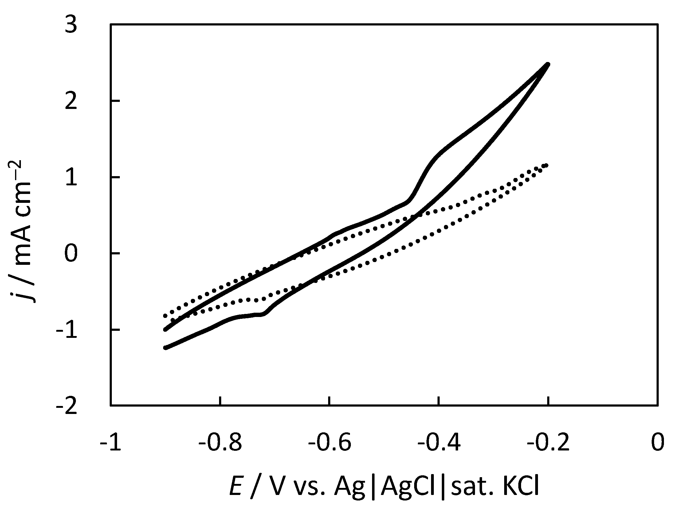
2.1. Electrochemical Performance of the Carbon Felt Electrode (CFE) Anode in the Indigo-Dye Fermenting Suspension

In this study, the indigo-dye fermenting suspension was poured into a cylinder-type container (Figure 1) and placed under quiescent conditions. Insoluble indigo is microbially reduced to water-soluble leuco-indigo, which is auto-oxidized by O2 near the liquid/air interface of the container. The reoxidized indigo frequently forms floating materials called Ai no Hana (indigo flower), together with some other insoluble materials. The catalytic reduction of indigo may predominantly proceed at the bottom of the container, which contains a sediment-rich suspension containing indigo-dye fermenting microorganisms.
Figure 2 shows the cyclic voltammograms of an indigo-dye fermenting suspension at the CFE placed at the bottom of the cylinder-type container under quiescent conditions without deaeration with an inert gas (e.g., nitrogen or argon). The solid and dotted lines represent the cyclic voltammograms at room temperature (ca. 25 °C) and 0 °C, respectively. At 0 °C, there was practically no microbial catalytic activity; thus, the cyclic voltammetry (CV) curve at 0 °C is considered as a background wave encompassing the non-catalytic redox wave. The anodic broad wave around −0.5 V was assigned to the oxidation of leuco-indigo, and the small peak around −0.7 V was assigned to the reduction of indigo (that may be adsorbed on the CFE). The result was in good agreement with the redox potential of the indigo/leuco-indigo couple that was reported to be −0.65 V (at pH = 10.7) [27]. The positive shift of the onset potential of the leuco-indigo oxidation may be ascribed to the slow kinetics of leuco-indigo at the CFE. Since the O2 reduction wave was not observed, we can conclude that the bottom of the container remained anaerobic, even when the container was maintained under atmospheric conditions.
At room temperature, the catalytic oxidation wave was observed from −0.45 V. The wave was ascribed to the microbially catalyzed acetaldehyde oxidation with the indigo/leuco-indigo couple as a redox mediator. Comparing the results at room temperature and 0 °C, we can determine that the steady-state catalytic oxidation current density reached approximately 1.5 mA cm−2 at −0.2 V. The measured pH of the indigo-dye fermenting suspension was 10.7.
Conversely, the reduction current observed at −0.71 V was ascribed to the acetaldehyde reduction, due to the microbially catalyzed reduction of acetaldehyde with the indigo/leuco-indigo couple as a redox mediator. At pH 10.7, the redox potentials of the aldehyde/ethanol couple and the indigo/leuco-indigo couple were −0.61 and −0.65 V, respectively. Although the acetaldehyde reduction with leuco-indigo was trending downhill from the thermodynamic viewpoint, the small potential difference (ca. ~40 mV) resulted in a slow catalytic reaction.

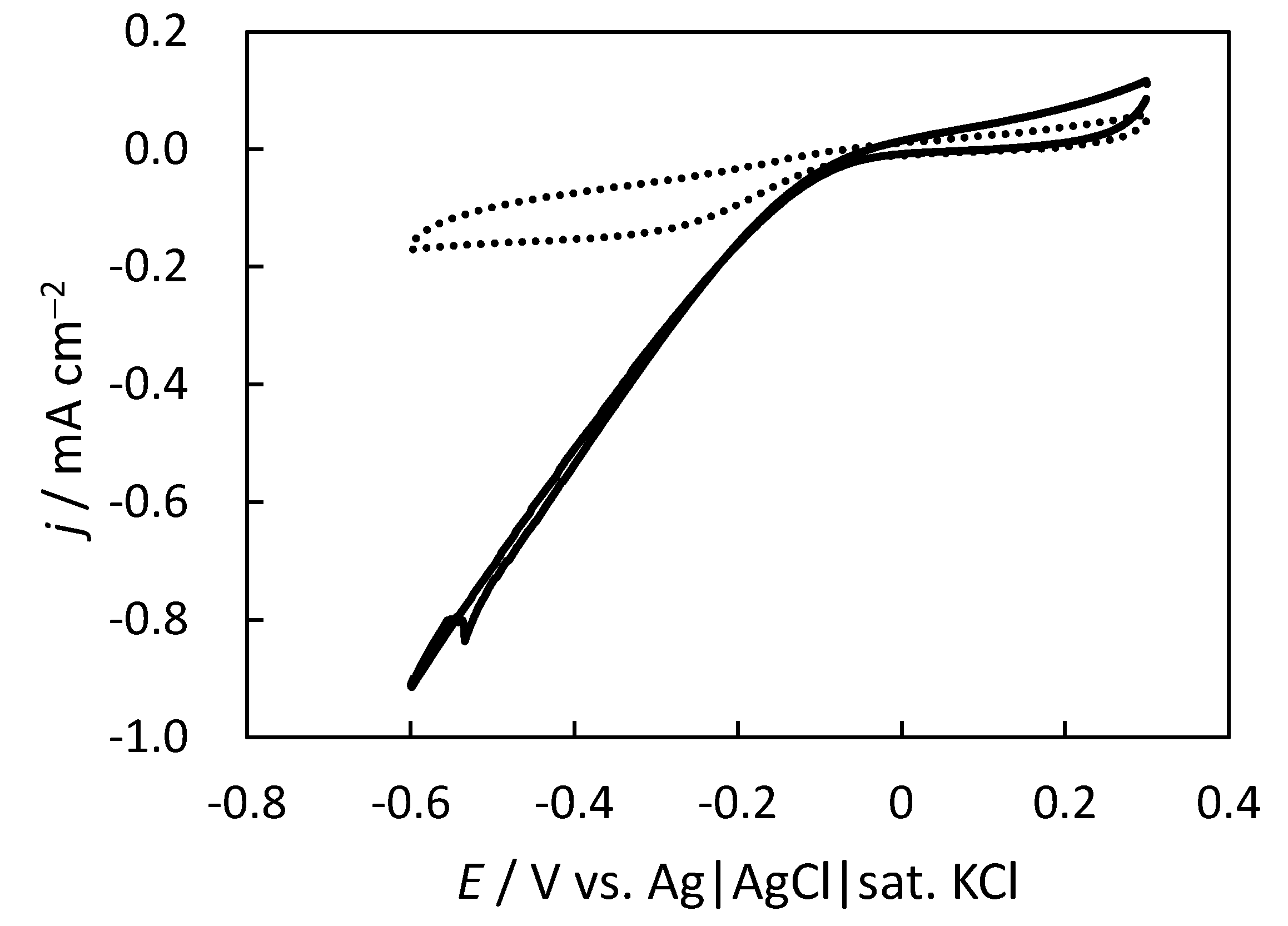
2.2. Gas-Diffusion-Type O2 Reduction with the Pt-Mesh Cathode

In this study, we selected Pt as the O2-reducing catalyst since the indigo-dye fermenting suspension is highly alkaline. Under such highly alkaline conditions, O2-reducing biocathodes utilizing MCO as a catalyst do not work well owing to the loss in the enzyme activity. As preliminary experiments, the performances of the Pt and carbon electrodes for O2 reduction were evaluated using a rotating ring-disk electrode (RRDE). Figure S2 shows the O2 reduction voltammograms of Pt and glassy carbon (GC) rotating electrodes at pH 10, 11, and 12, at 4000 rpm. The results are normalized by the limiting current at −0.8 V. Since the onset potential of the Pt electrode is more than 0.3 V higher than that of the GC electrode under highly alkaline conditions, we utilized Pt to construct a cathode with a low overpotential. Figure 3 shows the CV curves of the Pt mesh under quiescent and atmospheric conditions. The Pt mesh was placed at the gas–liquid interface (solid line) or immersed in the solution (dotted line) by adjusting the height of the tube, as shown in Figure 1. The lower part of the tube was covered with a dialysis membrane to avoid the influence of contaminants in the indigo-dye fermenting suspension, and the Pt mesh was placed on the dialysis membrane. The top views of the Pt-mesh cathodes are shown in Figure S3. The CV curves shown in Figure 3 are for the O2 reduction current. When the Pt mesh was immersed in the solution, the O2 reduction current curve exhibited a peak shape. This indicates the diffusion-controlled supply of O2, owing to the low solubility of the dissolved O2. Contrarily, when the Pt mesh was placed at the gas–liquid interface to construct a gas-diffusion-type electrode system, a considerably large and steady-state current density for the oxygen reduction reaction was realized without O2 depletion.

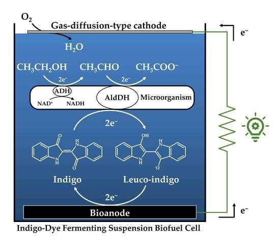
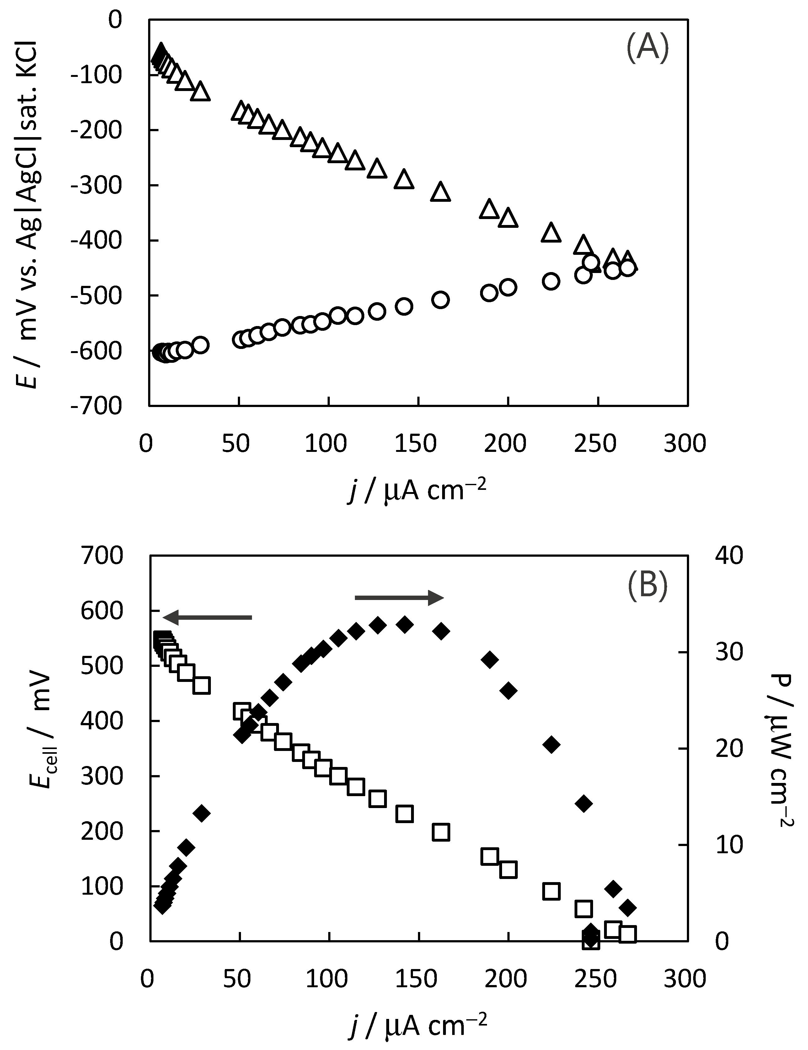
2.3. Construction of Indigo-Dye Fermenting Suspension Biofuel Cell

A semi-microbial biofuel cell was constructed by combining the CFE bioanode and the gas-diffusion-type Pt-mesh cathode in the indigo-dye fermenting suspension. The biofuel cell was operated under quiescent and atmospheric conditions at room temperature. The cell voltage, anode potential, and cathode potential were measured at the (quasi) steady state and at given resistances. The resistances were decreased stepwise. The potentials were recorded approximately 15 s after the change in the resistance.
In Figure 4, Panel A shows the anode (open circles) and cathode potentials (open triangles) as functions of the current density and Panel B shows the cell voltage (open squares) and the power density (filled diamonds) as functions of the current density. The open-circuit voltage (OCV) was 0.58 V, and the maximum power density was 32 µW cm−2 (320 mW m−2) when the cell voltage was 0.25 V. Considering the current–voltage characteristics of panel A, it can be concluded that the cathode performance is concentrated in the rate-limiting process. In addition, the measured cell voltage was almost equal to the sum of the measured potentials of the anode and the cathode. The video of the light-emitting diode (LED) powered using the indigo-dye fermenting suspension biofuel cell is shown in Video S1.

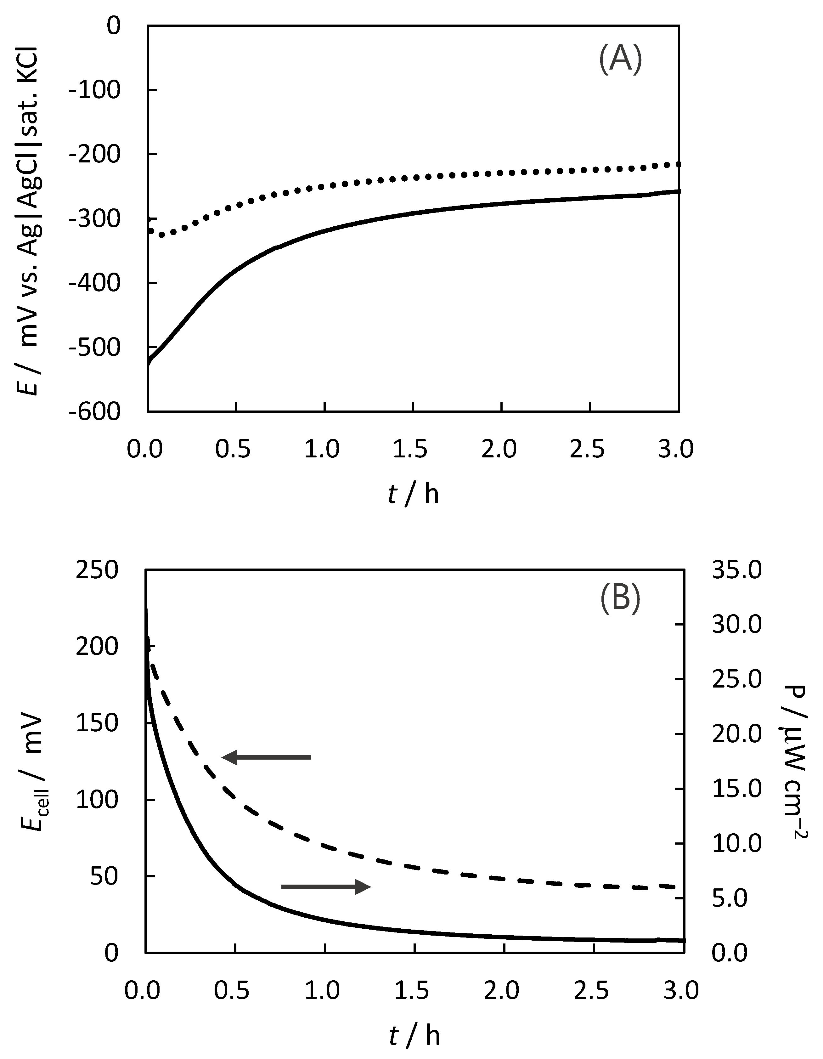
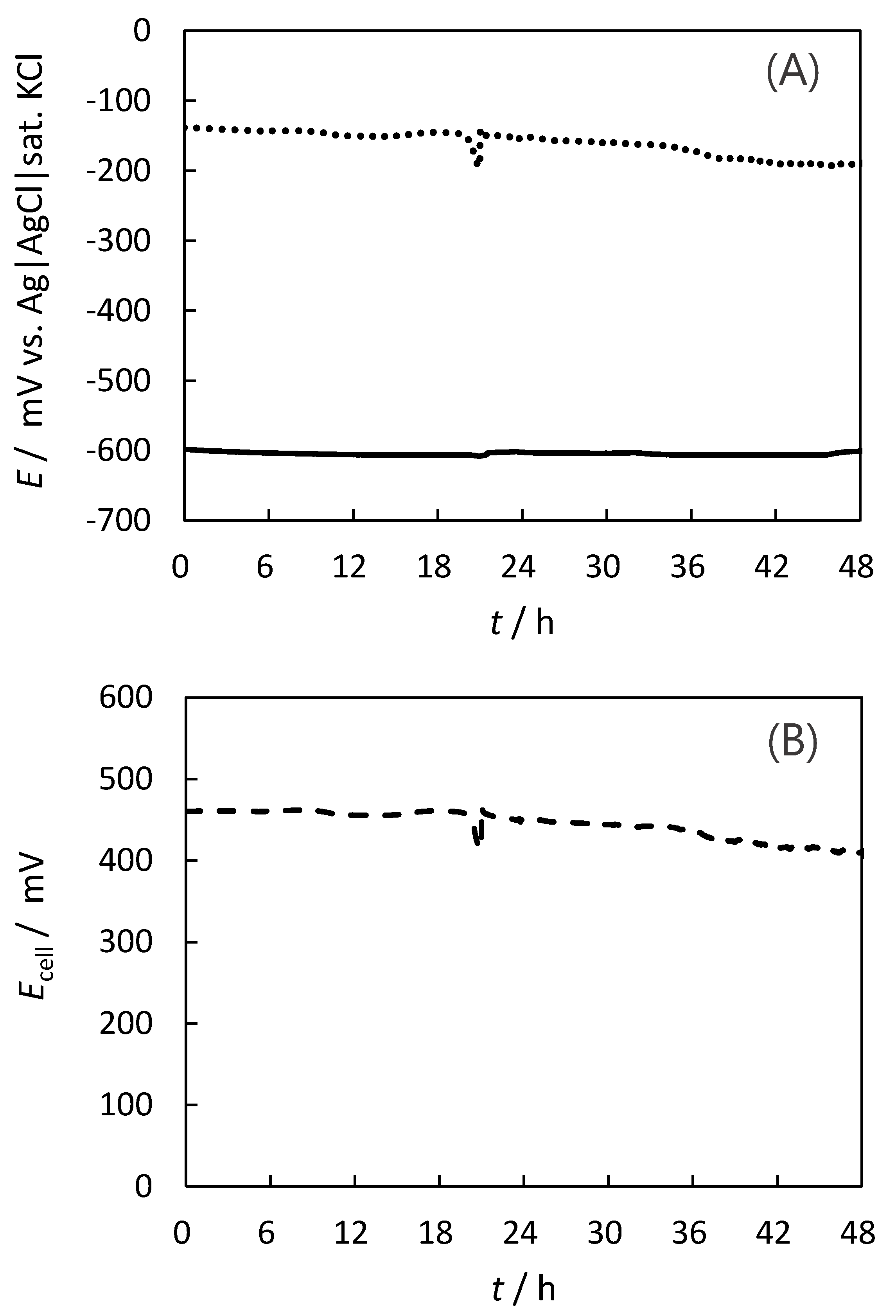
2.4. Stability for the Indigo-Dye Fermenting Suspension Biofuel Cell

The stability of the biofuel cell was evaluated in a continuous operation. Panels A and B (Figure 5) show the time dependence of the anode potential (panel A, solid line), cathode potential (panel A, dotted line), cell voltage (panel B, broken line), and power density (panel B, solid line) during the continuous operation at a resistance of 2000 Ω. We selected this resistance since the biofuel cell exhibited the highest power density in the initial state. The power density decreased rapidly in 0.5 h and became very small (less than 2 µW cm−2) after 3.0 h. From the results of Figure 5, Panel A, we can conclude that the cause of the decline is the degradation in the performance of the anode. Concerning the cathode side, the potential shifted toward the positive side. This is because the current density decreased with the performance degradation of the anode.
Conversely, a stability test with OCV measurements was also conducted. Panels A and B (Figure 6) show the time dependence of the anode potential (panel A, solid line), cathode potential (panel A, dotted line), and cell voltage (panel B, broken line) during the continuous operation at a resistance of 10 kΩ. The cell voltage decreased gradually, and after 48 h, it decreased by approximately 80 mV compared to the initial potential. For the long-term measurement (48 h), the state change of the gas–liquid interface, due to the evaporation, degraded the cathode performance. The spike-shaped noise at 22 h is due to the fine adjustment of the cylinder position to compensate for the decrease in the water level caused by the evaporation.
The anode showed stability for 48 h and has possibility to show stability for longer time. The microbiota in the indigo fermentation change slightly in the long term; however, their indigo-reducing activity is maintained for 6–8 months [29,30]. This implies that the MBFC using the indigo-dye fermenting suspension maintains its activity for longer periods. Moreover, there is a possibility that the activity is maintained for extended periods because the MFBC does not consume indigo, unlike the indigo-dyeing process. The stable activity which is derived from diversity of indigo-reducing microorganisms [29,30] is an advantage of the MBFC using the indigo-dye fermenting suspension. The clear mechanism of the electron transfer is also an advantage of this MBFC compared to the other MBFCs with mixed communities.

2.5. Challenges in Achieving High-Performance Biofuel Cells

To increase the power output of the indigo-dye fermenting suspension biofuel cells, it is necessary to improve the performance of both the anode and the cathode. For the anode, increasing the temperature is one of the methods to improve its performance. Figure S4 shows the CV curves measured at high temperatures of up to 58 °C. As the temperature increased, the catalytic current density also increased. In addition, activating the anode electrode by modifying the CFE with other carbon materials or by chemical modification to improve the electrode response to leuco-indigo may also help to increase the power output. The use of a buckypaper made of carbon nanotubes may also be effective as a solution to enhance power output. The material have already been reported [31,32]. Contrarily, for the cathode, it is necessary to construct a gas-diffusion-type system that is stable in the long term. One of the possible methods for improving stability linked to evaporation is constructing a membrane electrode assembly (MEA), which integrates a water-repellent protective layer, Pt-mesh cathode, and cellophane membrane in that order. The candidates of the protective layer are PTFE or Nafion membranes [33,34]. Since the membrane allows gas to pass through but completely prevents liquid leakage, it is possible to design the MEA to be placed on the side of the indigo-dye fermenting tank or to be used as a floating-type electrode on the surface of suspension [34]. In this cell design, the effect of evaporation can be neglected, so it is thought that the stability of a gas-diffusion-type cathode will be improved. Furthermore, the replacement of expensive Pt with less expensive catalysts is another necessary route for improving the technology.

3. Materials and Methods

3.1. Preparation of the Indigo-Dye Fermenting Suspension

A fresh indigo-dye fermenting suspension was prepared following the same method employed in our previous studies [27,28]. Twenty grams of Sukumo was mixed with 20 mL of hot water. Thereafter, 75 mL of the second lye (described below) was added, and the volume was made up to 200 mL using hot water. Subsequently, the solution was adjusted to pH 11 using slacked lime. Japanese Sake (1 mL) was added, and the resulting solution was incubated at 28 °C for 2 d. After incubation, wheat bran (0.2 g) mixed with hot water (5 mL) was added to the solution. Thereafter, the suspension was adjusted to pH 11 using slacked lime. The resulting suspension was incubated at 28 °C for 2 d. Fifty milliliters of the first lye (described below) and hot water (50 mL) were added to the suspension. The suspension was adjusted to pH 11 using slacked lime during incubation. After incubation at 28 °C for several days, the suspension, which exhibited indigo-dyeing activity, was used to prepare the semi-microbial fuel cell.

3.2. Preparation of Lye

The ash of oak and sawtooth oak (1 kg) was soaked in 5 L of hot water, mixed, and stored overnight. The resulting supernatant was obtained as the first lye. After the removal of the supernatant, the remaining ash was soaked in 10 L of hot water, mixed, and stored again overnight. The resulting supernatant was obtained as the second lye.

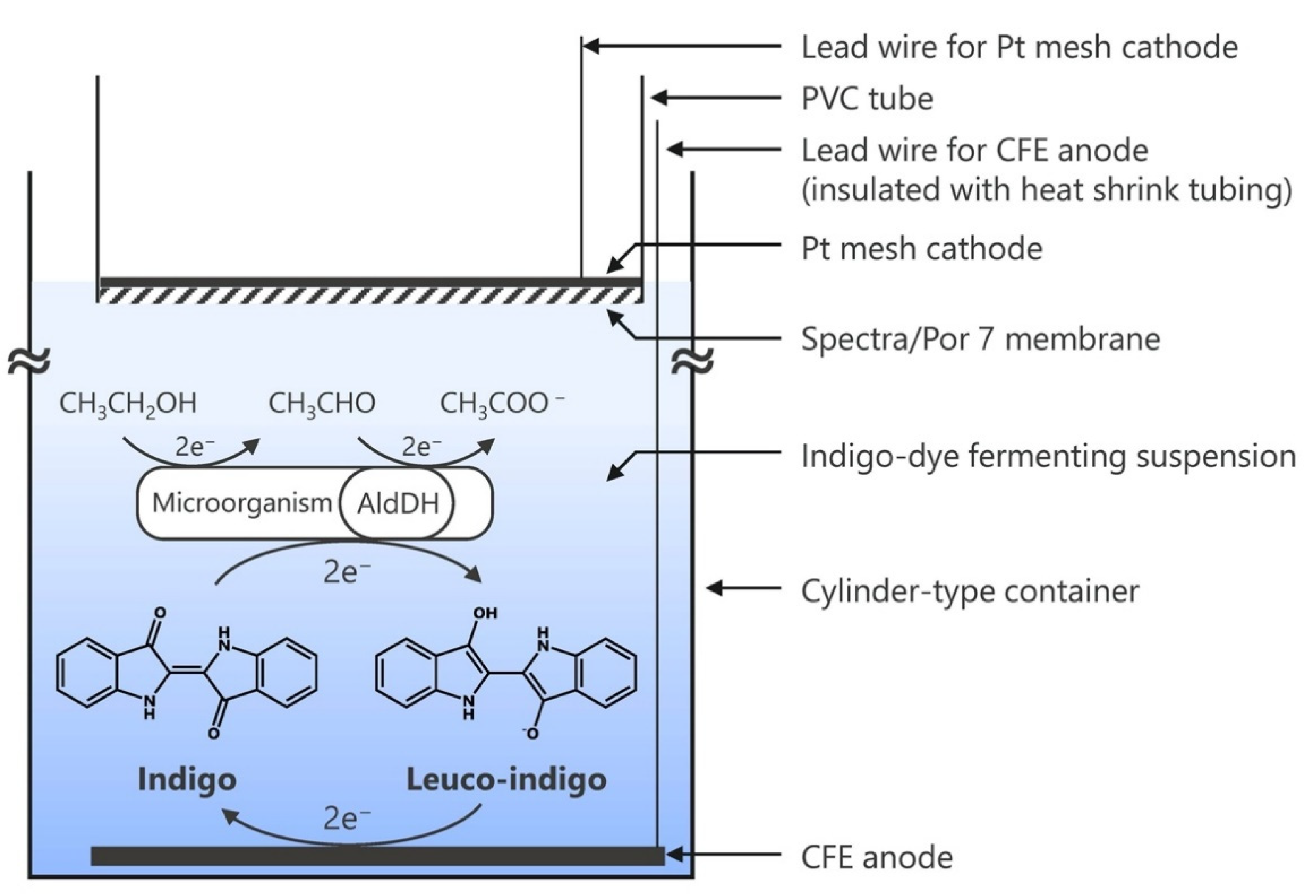
3.3. Preparation of the Semi-Microbial Fuel Cell

The indigo-dye fermenting suspension (100 mL) was poured gently into a cylinder-type container in which CFE (ca. 0.8 cm2, B0050, Toray, Japan, containing 17% of binder, basis weight = 50 g m−2) was already placed at the bottom. The CFE was sandwiched between Ti-mesh (Nilaco corp., Tokyo, Japan) and wrapped with 0.50 mm diameter Ti-wire (Nilaco corp., Tokyo, Japan). The Ti-wire was protected by heat shrink tubing and pulled out to the top of the cell as a lead wire. Thereafter, the container was stored overnight without deaeration. A polyvinyl chloride (PVC) tube (inner diameter: 13 mm) attached to a Spectra/Por 7 membrane (Repligen, Waltham, MA, USA) at the bottom was placed on the surface of the indigo-dye fermenting suspension. A Pt mesh (ca. 0.8 cm2, PT-358080, 80 mesh, Nilaco corp., Tokyo, Japan) was placed at the top of the membrane (Figure 1).

3.4. Evaluation of the Pt Electrode under an Alkaline Condition

Electrochemical measurements were performed using an ALS1205C voltammetric analyzer with a RRDE (BAS, Japan) at a rotating speed of 1000 rpm and a scan rate of 10 mV s−1, without bubbling, at room temperature in a 20 mM NaHCO3–Na2CO3 buffer (pH 10), 20 mM Na2HPO4–NaOH buffer (pH 11), or 20 mM Na2HPO4–NaOH buffer (pH 12). The RRDE had a GC disk electrode (diameter: 4 mm) and a Pt ring-disk electrode (7 mm o.d. and 5 mm i.d.). A Pt wire and a handmade Ag|AgCl|sat. KCl electrode were used as the counter and reference electrodes, respectively.

3.5. Evaluation of the CFE Anode and Pt-Mesh Cathode

Electrochemical measurements were performed using an ALS1205C voltammetric analyzer at room temperature (ca. 25 °C). To evaluate the anode, the CFE at the bottom of the container holding the indigo-dye fermenting suspension was used as the working electrode. To evaluate the cathode performance, the Pt-mesh cathode in the indigo-dye fermenting suspension was used as the working electrode and placed at the gas–liquid interface or an immersed position. The reference electrode was a handmade Ag|AgCl|sat. KCl electrode. The counter electrode was a 15 cm Pt wire (Nilaco corp., Tokyo, Japan), which was inserted vertically against the container. CV was conducted at a scan rate of 20 mV s−1 under quiescent and atmospheric conditions.

3.6. Indigo-Dye Fermenting Suspension Biofuel Cell

The anode and cathode of the MBFC were connected through a resistor (Yokogawa Hokushin Electric, Tokyo, Japan). The cell potentials were measured with electrometers HE-106A (Hokuto Denko, Tokyo, Japan) at given values of the resistance in the range from 100 kΩ to 5 Ω.

4. Conclusions

In this study, an indigo-dye fermenting suspension biofuel cell was constructed using a CFE electrode as a bioanode for acetaldehyde oxidation and a Pt-mesh electrode as a gas-diffusion-type cathode for O2 reduction. An anaerobic atmosphere was created by placing the bioanode electrode at the bottom of the cylindrical container holding the indigo-dye fermenting suspension. The biofuel cell was evaluated under quiescent and atmospheric conditions at room temperature. The OCV was 0.6 V, and the maximum output power was 32 µW cm−2 (320 mW m−2). In addition, the continuous stability was evaluated under given conditions starting with the highest power density; the power density decreased rapidly in 0.5 h with the degradation of the anode. Conversely, at the OCV, the anode potential exhibited high stability for two days. However, the OCV decreased by approximately 80 mV after 2 d compared to the initial value, owing to the performance degradation of the gas-diffusion-cathode system caused by the evaporation of the dispersion solution.

Supplementary Materials

The following are available online at https://0-www-mdpi-com.brum.beds.ac.uk/article/10.3390/catal11091080/s1, Figure S1: Fermentation processes for Aizome (Japanese indigo dyeing), Figure S2: Normalized linear sweep voltammograms of the Pt and GC rotating disk electrodes, Figure S3: Top view of the Pt-mesh cathode, Figure S4: Cyclic voltammogram of the CFE in the indigo-dye fermenting suspension, Video S1: LEDs powered by the indigo-dye fermenting suspension biofuel cell.

Author Contributions

Conceptualization, K.K., M.T., and E.S.; methodology, K.S. and K.K.; investigation, M.K., K.S., K.N., M.M., A.A., K.K., M.T., and E.S.; resources, K.S.; data curation, M.K. and K.S.; writing—original draft preparation, K.S. and M.T.; writing—review and editing, K.S., K.K., and M.T.; visualization, M.K. and K.S.; supervision, K.S., K.K., and M.T.; project administration, M.T. and E.S.; funding acquisition, M.T. All authors have read and agreed to the published version of the manuscript.

Funding

This research was funded by JSPS KAKENHI Grant Numbers 20K15432 (to M.T.).

Data Availability Statement

The data presented in this study are available on request from the corresponding author.

Acknowledgments

We thank N. Ariuchi (Shikoku University) and O. Nii (Nii Seiaisho) for teaching us the indigo-dye fermentation procedure. We also thank J. Ogawa (Kyoto University) for his cooperation.

Conflicts of Interest

The authors declare no conflict of interest.

References

  1. Rabaey, K.; Lissens, G.; Siciliano, S.D.; Verstraete, W. A microbial fuel cell capable of converting glucose to electricity at high rate and efficiency. Biotechnol. Lett. 2003, 25, 1531–1535. [Google Scholar] [CrossRef] [PubMed]
  2. Zhang, Y.; Mo, G.; Li, X.; Zhang, W.; Zhang, J.; Ye, J.; Huang, X.; Yu, C. A graphene modified anode to improve the performance of microbial fuel cells. J. Power Sources 2011, 196, 5402–5407. [Google Scholar] [CrossRef]
  3. Jung, S.; Regan, J.M. Comparison of anode bacterial communities and performance in microbial fuel cells with different electron donors. Appl. Microbiol. Biotechnol. 2007, 77, 393–402. [Google Scholar] [CrossRef]
  4. Chaudhuri, S.K.; Lovley, D.R. Electricity generation by direct oxidation of glucose in mediatorless microbial fuel cells. Nat. Biotechnol. 2003, 21, 1229–1232. [Google Scholar] [CrossRef]
  5. Ringeisen, B.R.; Henderson, E.; Wu, P.K.; Pietron, J.; Ray, R.; Little, B.; Biffinger, J.C.; Jones-Meehan, J.M. High power density from a miniature microbial fuel cell using Shewanella oneidensis DSP10. Environ. Sci. Technol. 2006, 40, 2629–2634. [Google Scholar] [CrossRef] [Green Version]
  6. Bretschger, O.; Obraztsova, A.; Sturm, C.A.; Chang, I.S.; Gorby, Y.A.; Reed, S.B.; Culley, D.E.; Reardon, C.L.; Barua, S.; Romine, M.F.; et al. Current production and metal oxide reduction by Shewanella oneidensis MR-1 wild type and mutants. Appl. Environ. Microbiol. 2007, 73, 7003–7012. [Google Scholar] [CrossRef] [Green Version]
  7. Watson, V.J.; Logan, B.E. Power production in MFCs inoculated with Shewanella oneidensis MR-1 or mixed cultures. Biotechnol. Bioeng. 2010, 105, 489–498. [Google Scholar] [CrossRef] [PubMed]
  8. Rosenbaum, M.; Cotta, M.A.; Angenent, L.T. Aerated Shewanella oneidensis in continuously fed bioelectrochemical systems for power and hydrogen production. Biotechnol. Bioeng. 2010, 105, 880–888. [Google Scholar] [CrossRef] [PubMed]
  9. Kim, J.R.; Jung, S.H.; Regan, J.M.; Logan, B.E. Electricity generation and microbial community analysis of alcohol powered microbial fuel cells. Bioresour. Technol. 2007, 98, 2568–2577. [Google Scholar] [CrossRef]
  10. Slate, A.J.; Whitehead, K.A.; Brownson, D.A.C.; Banks, C.E. Microbial fuel cells: An overview of current technology. Renew. Sustain. Energy Rev. 2019, 101, 60–81. [Google Scholar] [CrossRef]
  11. Sund, C.J.; McMasters, S.; Crittenden, S.R.; Harrell, L.E.; Sumner, J.J. Effect of electron mediators on current generation and fermentation in a microbial fuel cell. Appl. Microbiol. Biotechnol. 2007, 76, 561–568. [Google Scholar] [CrossRef]
  12. Rabaey, K.; Boon, N.; Höfte, M.; Verstraete, W. Microbial phenazine production enhances electron transfer in biofuel cells. Environ. Sci. Technol. 2005, 39, 3401–3408. [Google Scholar] [CrossRef] [PubMed]
  13. Takeuchi, R.; Sugimoto, Y.; Kitazumi, Y.; Shirai, O.; Ogawa, J.; Kano, K. Electrochemical study on the extracellular electron transfer pathway from Shewanella strain Hac319 to electrodes. Anal. Sci. 2018, 34, 1177–1182. [Google Scholar] [CrossRef] [Green Version]
  14. von Canstein, H.; Ogawa, J.; Shimizu, S.; Lloyd, J.R. Secretion of flavins by Shewanella species and their role in extracellular electron transfer. Appl. Environ. Microbiol. 2008, 74, 615–623. [Google Scholar] [CrossRef] [PubMed] [Green Version]
  15. Chin-A-Woeng, T.F.C.; Bloemberg, G.V.; Lugtenberg, B.J.J. Phenazines and their role in biocontrol by Pseudomonas bacteria. New Phytol. 2003, 157, 503–523. [Google Scholar] [CrossRef] [Green Version]
  16. Reguera, G.; McCarthy, K.D.; Mehta, T.; Nicoll, J.S.; Tuominen, M.T.; Lovley, D.R. Extracellular electron transfer via microbial nanowires. Nature 2005, 435, 1098–1101. [Google Scholar] [CrossRef] [PubMed]
  17. Call, D.F.; Logan, B.E. Lactate oxidation coupled to iron or electrode reduction by Geobacter sulfurreducens PCA. Appl. Environ. Microbiol. 2011, 77, 8791–8794. [Google Scholar] [CrossRef] [Green Version]
  18. Solomon, E.I.; Sundaram, U.M.; Machonkin, T.E. Multicopper oxidases and oxygenases. Chem. Rev. 1996, 96, 2563–2605. [Google Scholar] [CrossRef] [PubMed]
  19. Tarasevich, M.R.; Yaropolov, A.I.; Bogdanovskaya, V.A.; Varfolomeev, S.D. Electrocatalysis of a cathodic oxygen reduction by laccase. J. Electroanal. Chem. 1979, 104, 393–403. [Google Scholar] [CrossRef]
  20. Shleev, S.; Jarosz-Wilkolazka, A.; Khalunina, A.; Morozova, O.; Yaropolov, A.; Ruzgas, T.; Gorton, L. Direct electron transfer reactions of laccases from different origins on carbon electrodes. Bioelectrochemistry 2005, 67, 115–124. [Google Scholar] [CrossRef]
  21. Wanibuchi, M.; Kitazumi, Y.; Shirai, O.; Kano, K. Enhancement of the direct electron transfer-type bioelectrocatalysis of bilirubin oxidase at the interface between carbon particles. Electrochemistry 2021, 89, 43–48. [Google Scholar] [CrossRef]
  22. Murao, S.; Tanaka, N. Purification and some properties of bilirubin oxidase of Myrothecium verrucaria MT-1. Agric. Biol. Chem. 1982, 46, 2499–2503. [Google Scholar] [CrossRef]
  23. Tsujimura, S.; Nakagawa, T.; Kano, K.; Ikeda, T. Kinetic study of direct bioelectrocatalysis of dioxygen reduction with bilirubin oxidase at carbon electrodes. Electrochemistry 2004, 72, 437–439. [Google Scholar] [CrossRef] [Green Version]
  24. Mano, N.; Edembe, L. Bilirubin oxidases in bioelectrochemistry: Features and recent findings. Biosens. Bioelectron. 2013, 50, 478–485. [Google Scholar] [CrossRef]
  25. Kataoka, K.; Komori, H.; Ueki, Y.; Konno, Y.; Kamitaka, Y.; Kurose, S.; Tsujimura, S.; Higuchi, Y.; Kano, K.; Seo, D.; et al. Structure and function of the engineered multicopper oxidase CueO from Escherichia coli—Deletion of the methionine-rich helical region covering the substrate-binding site. J. Mol. Biol. 2007, 373, 141–152. [Google Scholar] [CrossRef] [Green Version]
  26. Miura, Y.; Tsujimura, S.; Kurose, S.; Kamitaka, Y.; Kataoka, K.; Sakurai, T.; Kano, K. Direct electrochemistry of CueO and its mutants at residues to and near type I Cu for oxygen-reducing biocathode. Fuel Cells 2009, 9, 70–78. [Google Scholar] [CrossRef]
  27. Nakagawa, K.; Takeuchi, M.; Kikuchi, M.; Kiyofuji, S.; Kugo, M.; Sakamoto, T.; Kano, K.; Ogawa, J.; Sakuradani, E. Mechanistic insights into indigo reduction in indigo fermentation: A voltammetric study. Electrochemistry 2021, 89, 25–30. [Google Scholar] [CrossRef]
  28. Nakagawa, K.; Takeuchi, M.; Kikuchi, M.; Tada, M.; Sakamoto, T.; Kano, K.; Ogawa, J.; Sakuradani, E. Voltammetric in-situ monitoring of leuco-indigo in indigo-fermenting suspensions. J. Biosci. Bioeng. 2021, 131, 565–571. [Google Scholar] [CrossRef] [PubMed]
  29. Tu, Z.; Lopes, H.F.S.; Igarashi, K.; Yumoto, I. Characterization of the microbiota in long- and short-term natural indigo fermentation. J. Ind. Microbiol. Biotechnol. 2019, 46, 1657–1667. [Google Scholar] [CrossRef]
  30. Aino, K.; Hirota, K.; Okamoto, T.; Tu, Z.; Matsuyama, H.; Yumoto, I. Microbial communities associated with indigo fermentation that thrive in anaerobic alkaline environments. Front. Microbiol. 2018, 9, 2196. [Google Scholar] [CrossRef]
  31. Gross, A.; Holzinger, M.; Cosnier, S. 1. Buckypapers for Bioelectrochemical Applications: Bioelectrochemistry: Design and Applications of Biomaterials; Cosnier, S., Ed.; De Gruyter: Berlin, Germany; Boston, MA, USA, 2019; pp. 1–22. [Google Scholar] [CrossRef]
  32. Gross, A.; Chen, X.; Giroud, F.; Abreu, C.; Goff, A.; Holzinger, M.; Cosnier, S. A High Power Buckypaper Biofuel Cell: Exploiting 1,10-Phenanthroline-5,6-dione with FAD-Dependent Dehydrogenase for Catalytically-Powerful Glucose Oxidation. ACS Catal. 2017, 7, 4408. [Google Scholar] [CrossRef]
  33. So, K.; Ozawa, H.; Onizuka, M.; Komukai, T.; Kitazumi, Y.; Shirai, O.; Kano, K. Highly permeable gas diffusion electrodes with hollow carbon nanotubes for bilirubin oxidase-catalyzed. Electrochim. Acta. 2017, 246, 794. [Google Scholar] [CrossRef]
  34. Shleev, S.; Shumakovich, G.; Morozova, O.; Yaropolov, A. Stable “floating”air diffusion biocathode based on direct electron transfer reactions between carbon particles and high redox potential laccase. Fuel Cells 2010, 10, 726. [Google Scholar] [CrossRef] [Green Version]
Figure 1. Proposed redox reactions and schematic of an indigo-dye fermenting suspension biofuel cell. The CFE anode was placed at the bottom of the cylinder-type container. The Pt-mesh cathode was placed at the top of the membrane. The projected surface area of the CFE anode and the Pt-mesh cathode was 0.8 cm2.
Catalysts 11 01080 g001
Figure 2. Cyclic voltammograms at the CFE in the indigo-dye fermenting suspension. The scan rate was 20 mV s−1. Measurements were conducted at room temperature (ca. 25 °C) (solid line) and 0 °C (dotted line) under quiescent and atmospheric conditions.
Catalysts 11 01080 g002
Figure 3. Cyclic voltammograms of the Pt-mesh electrode. The scan rate was 20 mV s−1. Measurements were conducted at room temperature (ca. 25 °C) under quiescent and atmospheric conditions. The Pt mesh was placed at the gas–liquid interface (solid line) and immersed in the solution (dotted line).
Catalysts 11 01080 g003
Figure 4. (A) Polarization curves of the indigo-dye fermenting suspension biofuel cell. The measured potentials of the anode (open circles) and the cathode (open triangles) are plotted as a function of the current density. (B) The cell voltage (open squares) and the power density (filled diamonds) of the indigo-dye fermenting suspension biofuel cell are plotted as a function of the current density.
Catalysts 11 01080 g004
Figure 5. Continuous monitoring of the stability of the indigo-dye fermenting suspension biofuel cell under the operating conditions. (A) The measured potentials of the anode (solid line) and the cathode (dotted line) are plotted as a function of time. (B) The cell voltage (dashed line) and the power density (solid line) are plotted as a function of time. The measurements were performed in the indigo-dye fermenting suspension at room temperature under quiescent and atmospheric conditions. The load resistance was 2000 Ω.
Catalysts 11 01080 g005
Figure 6. Continuous monitoring of the stability of the indigo-dye fermenting suspension biofuel cell with OCV measurements. (A) The measured potentials of the anode (solid line) and the cathode (dotted line) are plotted as a function of time. (B) The cell voltage (dashed line) is plotted as a function of time. The measurements were performed in the indigo-dye fermenting suspension at room temperature under quiescent and atmospheric conditions. The load resistance was 10 kΩ.
Catalysts 11 01080 g006
Publisher’s Note: MDPI stays neutral with regard to jurisdictional claims in published maps and institutional affiliations.

