
Catalytic Tar Conversion in Two Different Hot Syngas Cleaning Systems


1
Institute for Technical Chemistry, Karlsruhe Institute of Technology, Hermann-von-Helmholtz-Platz 1, 76344 Eggenstein-Leopoldshafen, Germany
2
Institute for Micro Process Engineering, Karlsruhe Institute of Technology, Hermann-von-Helmholtz-Platz 1, 76344 Eggenstein-Leopoldshafen, Germany
*
Author to whom correspondence should be addressed.
Catalysts 2021, 11(10), 1231; https://0-doi-org.brum.beds.ac.uk/10.3390/catal11101231
Submission received: 15 September 2021
/
Revised: 7 October 2021
/
Accepted: 9 October 2021
/
Published: 13 October 2021
(This article belongs to the Special Issue Catalysts in Production of Clean Gasification Gas)
Abstract
:Tar in the product gas of biomass gasifiers reduces the efficiency of gasification processes and causes fouling of system components and pipework. Therefore, an efficient tar conversion in the product gas is a key step of effective and reliable syngas production. One of the most promising approaches is the catalytic decomposition of the tar species combined with hot syngas cleaning. The catalyst must be able to convert tar components in the synthesis gas at temperatures of around 700 °C downstream of the gasifier without preheating. A Ni-based doped catalyst with high activity in tar conversion was developed and characterized in detail. An appropriate composition of transition metals was applied to minimize catalyst coking. Precious metals (Pt, Pd, Rh, or a combination of two of them) were added to the catalyst in small quantities. Depending on the hot gas cleaning system used, both transition metals and precious metals were co-impregnated on pellets or on a ceramic filter material. In the case of a pelletized-type catalyst, the hot gas cleaning system revealed a conversion above 80% for 70 and 110 h. The catalyst composed of Ni, Fe, and Cr oxides, promoted with Pt and impregnated on a ceramic fiber filter composed of Al2O3(44%)/SiO2(56%), was the most active catalyst for a compact cleaning system. This catalyst was catalytically active with a naphthalene conversion of around 93% over 95 h without catalyst deactivation.
1. Introduction
In the gasification of biomass, a gas mixture that essentially consists of the components CO, CO2, H2, H2O and higher hydrocarbons, as well as aromatic compounds (condensable tar), is produced. In addition, the gas contains small amounts of impurities, such as NH3, H2S, and HCl, but also HCN and COS. The tar content depends on the feedstock, the process parameters, and the reactor type. Irrespective of the reactor type, tar is produced as an undesirable byproduct of thermochemical conversion and lasts in a range between 0.1 g/m3 for a co-current fixed-bed reactor and 150 g/m3 for a counter-current fixed-bed reactor [1]. The presence of tar in the product gas can be responsible for fouling or reducing the overall efficiency of processes and may also cause blockage and corrosion of equipment, such as gas engines, gas turbines, and fuel cell-based power generators. The tar concentration for use of the gas in an internal combustion engine for the combined production of electricity and thermal energy is limited [2] to a maximum of 0.01 g/m³. Therefore, the successful implementation of gasification technology depends largely on effective and efficient gas cleaning and tar removal from the product gas. One of the most promising methods to overcome this problem is the catalytic decomposition of tar species, where the energy content of the tar can be converted into fuel gas. In addition, catalytic conversion has the potential to reduce the thermal and economic effects of high-temperature operations. Here, the thermodynamic efficiency losses can be minimized, since no additional energy input is required [3]. Over the last few decades, several metals and compounds, both naturally occurring and industrially produced, have been tested as tar cracking and reforming catalysts. Silica, zeolite, olivine, and dolomite are among the most used natural minerals [4,5,6,7]. Standing out for their catalytic activities, these minerals, together with alumina, are also the most widely used supports for catalytic active metals and metal oxides [8,9,10]. Ni-based catalysts for tar elimination have also been thoroughly investigated [8,9,10,11,12,13,14]. It has been reported that these catalysts reveal many problems due to coke deposition, but they can achieve almost complete decomposition of both tar and ammonia content. Among the most promising Ni-supported metal oxide catalysts for catalytic performance in steam reforming and resistance to coke deposition was 15 wt% Ni/CeO2 (75%) ZrO2 (25%) [14]. Despite the many promising advantages of Ni-based catalysts, complete tar conversion is achieved only above 800 °C. Tar reforming at a lower temperature range (550–650 °C) was tested successfully with catalysts containing (0.7–2.35 wt%) Ru, Rh, Pd, or Pt on a support consisting of 60% wt% CeO2 on SiO2 [15]. Proprietary Pt-based catalysts already provide the complete conversion of tar model substances above 350 °C [16], enabling catalyst operation in the synthesis gas downstream of a gasifier without preheating.
In the last two decades, not only catalytic materials have been investigated in tar conversion but also more compact systems with catalytic filters. By using such a material, particle filtration and tar conversion can be combined in one process step. The implementation of a catalyst in the filter material can be carried out by (a) coating the filter material with the catalyst; (b) introducing the catalyst into the structure of the filter, for example, by mixing the catalyst with ceramic grain and binder; or (c) using an additional porous material inner tube to incorporate a catalyst particle layer in between [3]. Nacken et al. [17] followed method (c) and developed a catalytic filter element with a catalyst particle layer with a particle size fraction between 0.1 and 0.3 mm. Using Mg6Ni (S) (6% by weight Ni, MgO-supported catalyst) as a catalyst, they achieved complete conversion of naphthalene at a filtration rate of 90 m h−1 (2.5 cm s−1) in the presence of 100 ppmv H2S for 100 h at 800 °C. Zhang et al. [18] developed a nickel-activated catalytic filter (1% by weight Ni + 0.1, 0.5 or 1.0% by weight CaO; CaO should protect the catalyst against sulfur poisoning) using a urea precipitation process. By implementing the catalyst in α-Al2O3-based filter disks as a model of a candle filter, the authors follow method (b). The catalytic filters produced in this way were used for the decomposition of benzene (tar model compound). The experiments were monitored for 60 min, and a benzene conversion of 93% (50 ppm H2S) and 78% (100 ppmv H2S) was achieved in the steady state with a filtration gas velocity of 2.5 cm·s−1. In addition, studies have been carried out to suggest the optimal Ni/CaO ratio for the sulfur resistance of the nickel-activated catalytic filter.
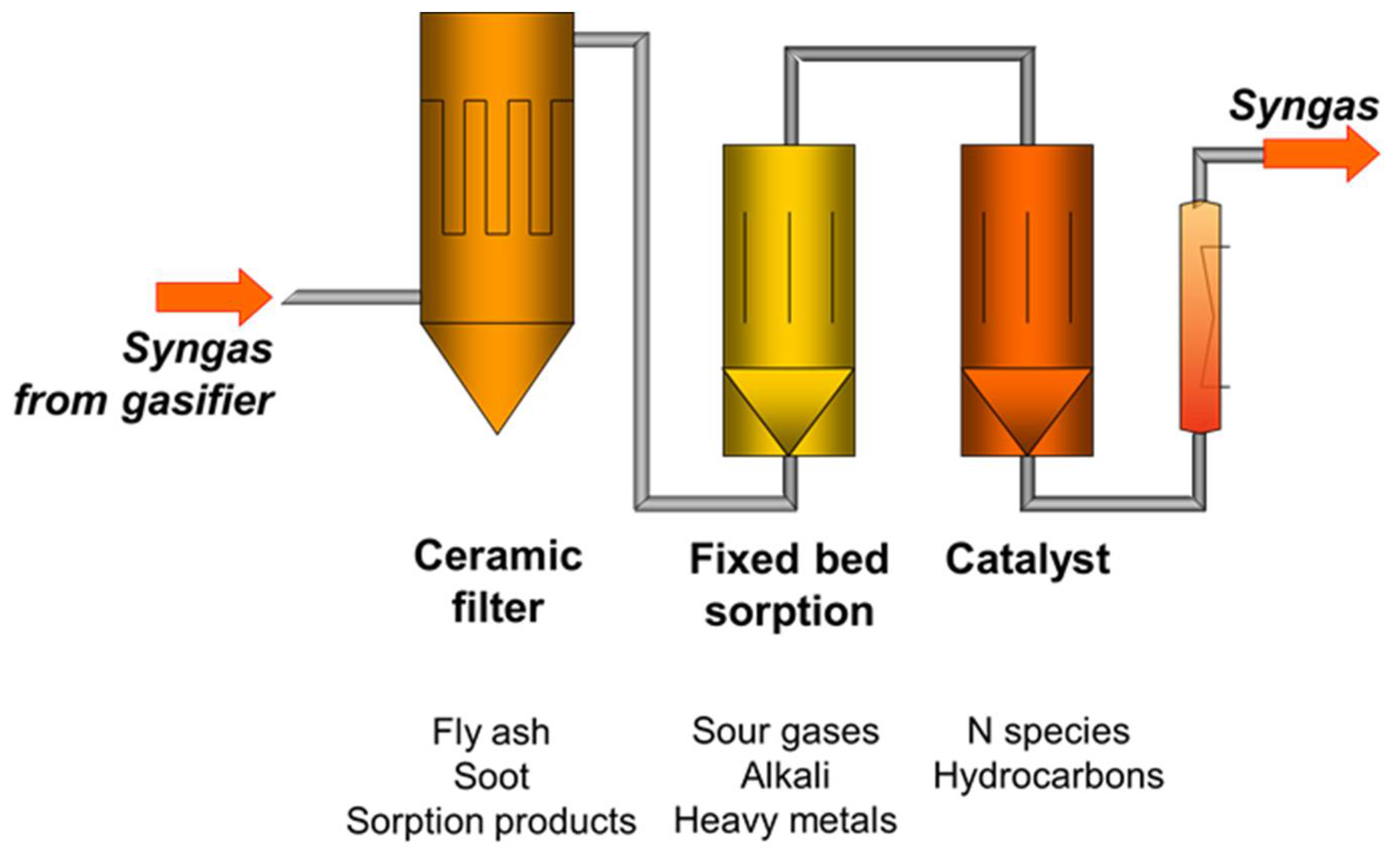
To increase the performance of the catalytic stage, not only H2S has to be removed upstream. In Figure 1, a multi-stage hot gas cleaning system with a ceramic filter, fixed-bed sorption, and catalyst is illustrated.
In the ceramic filter stage, fly ash and soot are filtered to prevent fixed-bed reactors from fouling. In the fixed-bed sorption stage, sour gases, such as H2S and HCl, can react with appropriate sorption material. The sorption material is spent during its lifetime and has to be refreshed from time to time. In the catalytic stage, hydrocarbons and possible N-species are converted.
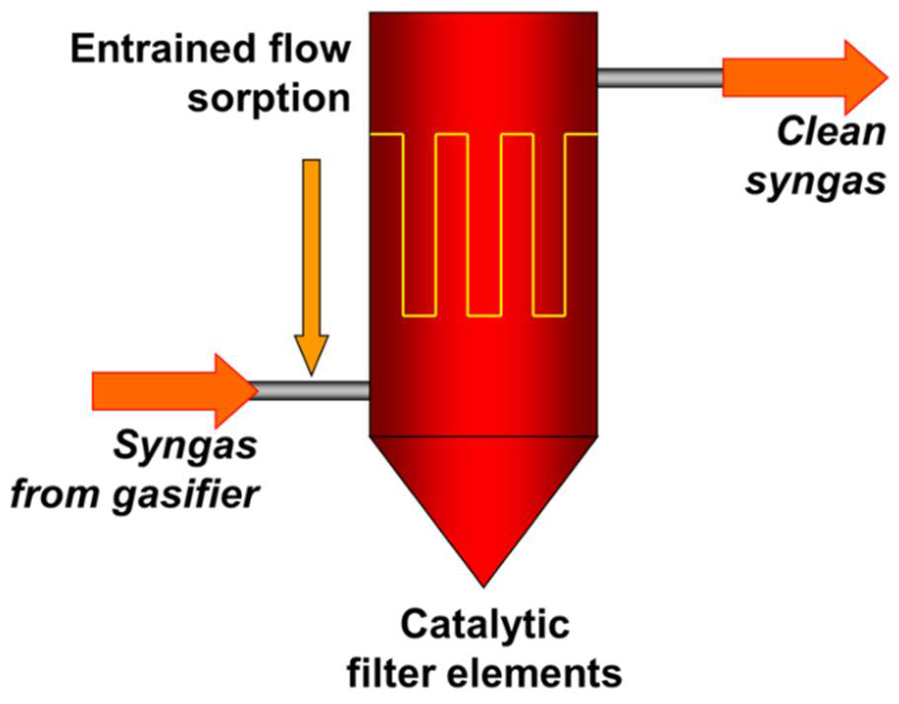
To overcome the problem of the limited lifetime of the fixed-bed sorption stage, especially at high concentrations of contaminants, a continuously working entrained-flow sorption system upstream of the filter stage can be applied. Additionally, the switch from standard ceramic filter elements to catalytic filter elements leads to a highly integrated hot gas cleaning system with significantly reduced investment costs (see Figure 2).
Regardless of the system used (fixed-bed catalytic stage or catalytic filter elements), the following reactions occur over supported nickel-based catalysts in steam and carbon dioxide atmosphere:
Water–gas shift: CO + H2O ↔ CO2 + H2
Carbon deposition: 2 CO ↔ C + CO2
The current investigation focuses on the development of both pellet catalysts for hot gas cleaning systems with a fixed-bed option and catalytic candle filters for compact catalytic hot gas cleaning systems with entrained-flow sorption. In both cases, the catalyst must be active long term at temperatures around 700 °C. A new carrier material made of aluminum oxide and montmorillonite was developed for pellet catalysts. In addition, the coating process was optimized with regard to the optimal impregnation process for the pellet material and the ceramic candle. A strategy of long-term stability with in situ regeneration for both catalytic materials was implemented. The catalytic element compositions of Ni, Fe, and Cr or Mn were selected as a basis for the tar catalysts. The metals for the composition of our catalysts were not chosen randomly. Nickel is known to be the most effective and suitable catalyst for steam reforming [13,14]. The combination of Ni and Fe is also effective for NH3 conversion [19]. Cr and Mn are known to reduce coke deposits on the catalyst surface, which arise during tar conversion [20,21]. To ensure that the catalysts are also effective at lower temperatures, small amounts of Pt, Pd, Rh, or Ru and in some samples, a combination of two of these noble metals were used.
2. Results and Discussion
2.1. Pellet Catalysts for Tar Conversion
2.1.1. Porous Texture Analysis
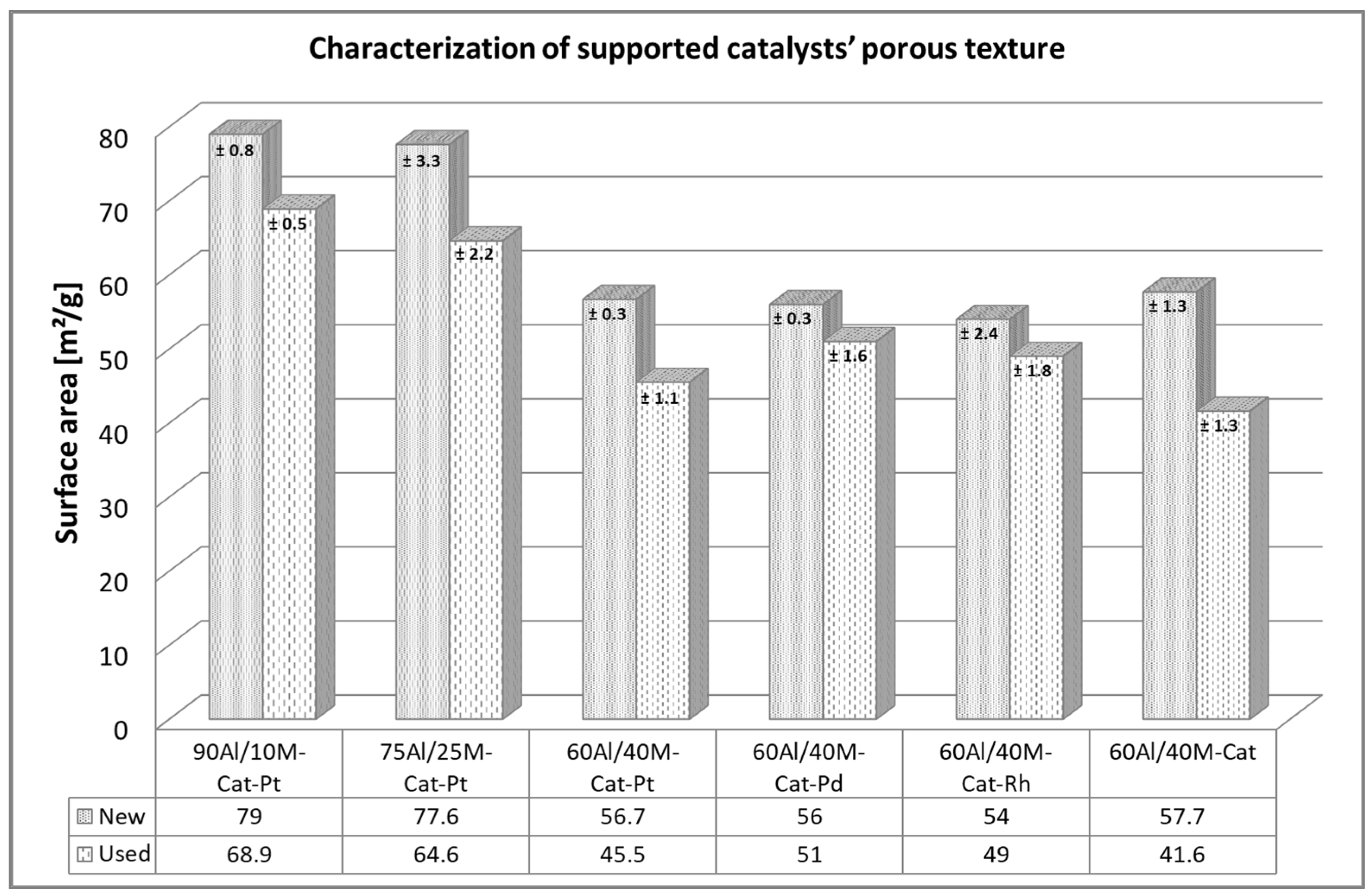
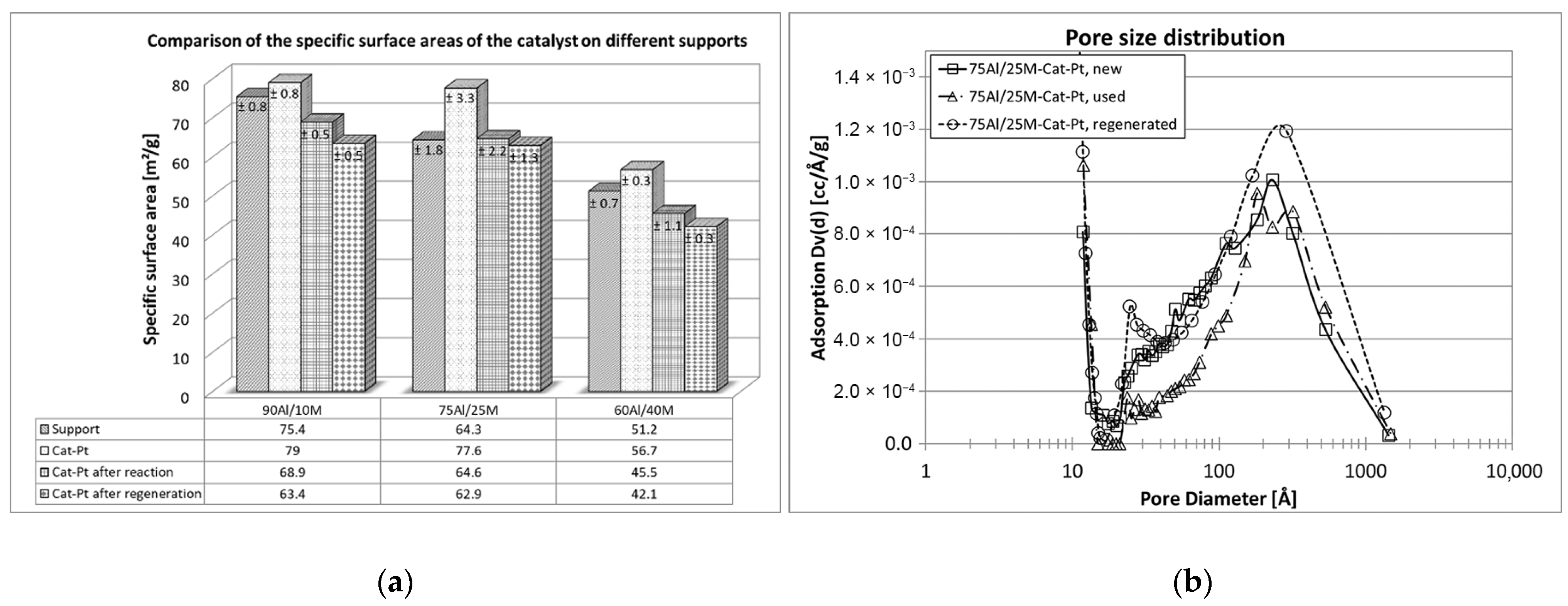
The BET-specific surface area shows the extent of the adsorption capacity of the supported catalysts. The higher the capacity, the better the reforming reaction of the tar. Therefore, it is important that this capacity remains unchanged during the reaction. A comparison of the specific surface areas before and after the test was useful to obtain an idea of this aspect. As can be seen in Figure 3 in particular, the preparation procedure of the support material has a great influence on the specific surface of the new catalysts. The smallest specific surface area belongs to the catalyst on a 60/40 alumina and montmorillonite mixture, and about 30% larger surface area was measured for catalysts on the mixtures 75/25 and 90/10. Doping with noble metal had no measurable influence on the specific surface area. Nonetheless, all tested catalysts lost their initial specific surface areas after the first long-term naphthalene reforming. A decrease of about 15–20% in specific surface area was noted for all used catalysts. Certainly, the coke deposit, which closed the narrowest pores of the support pellets and the access to the catalysts, was responsible for the decrease in the specific surface areas [22,23].
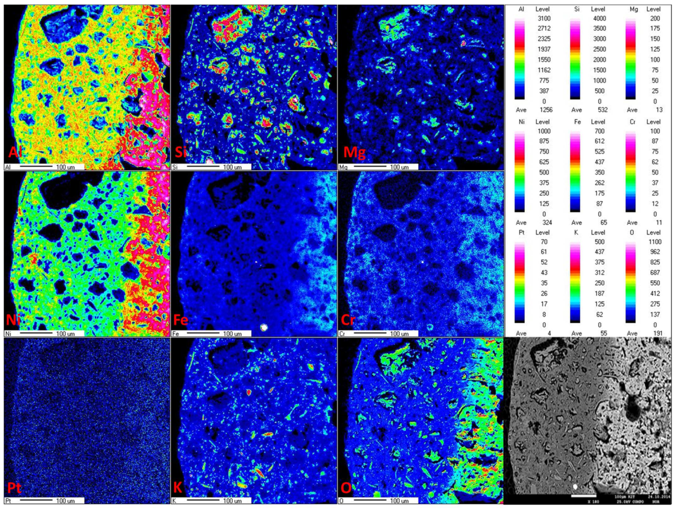
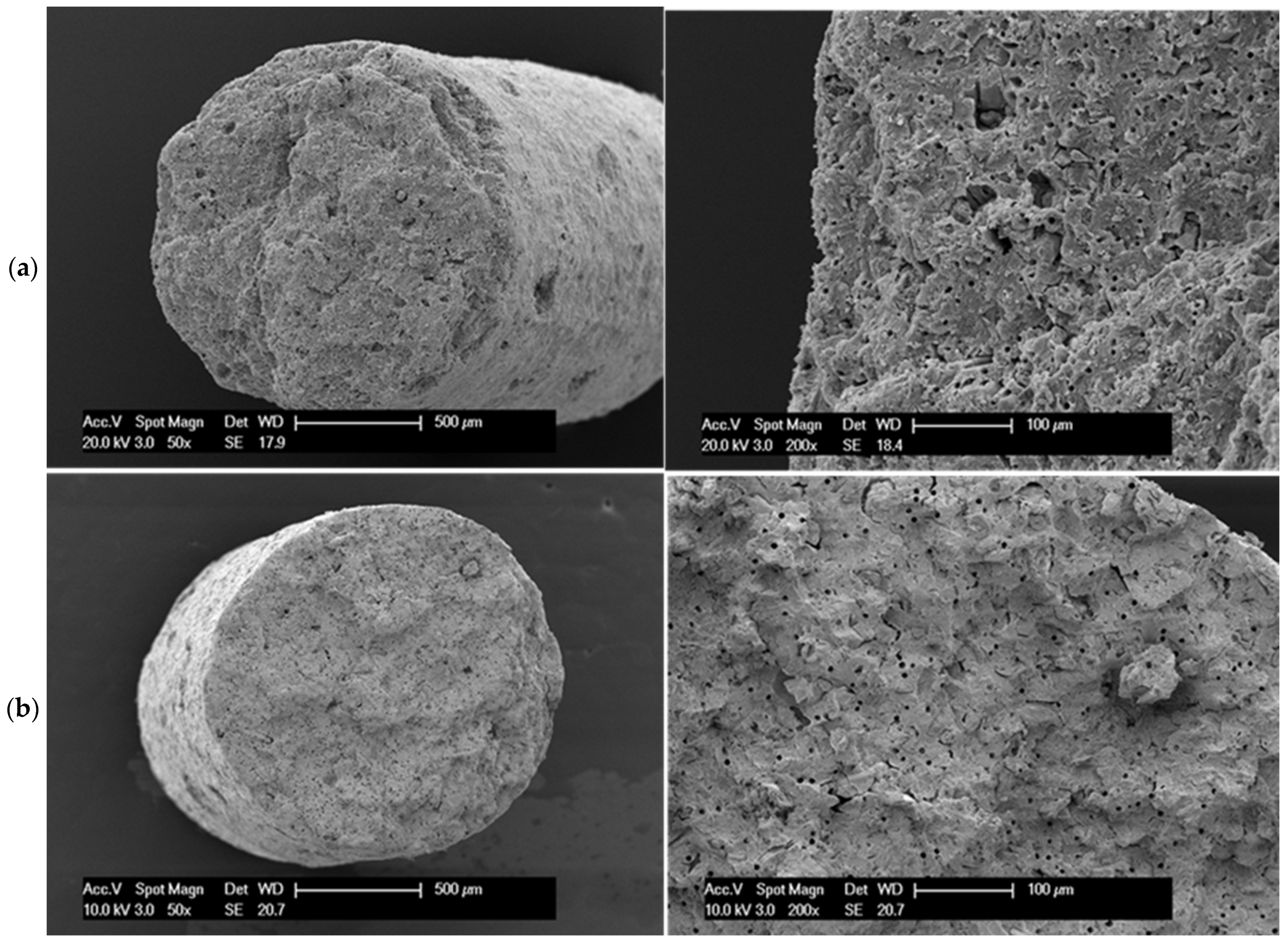
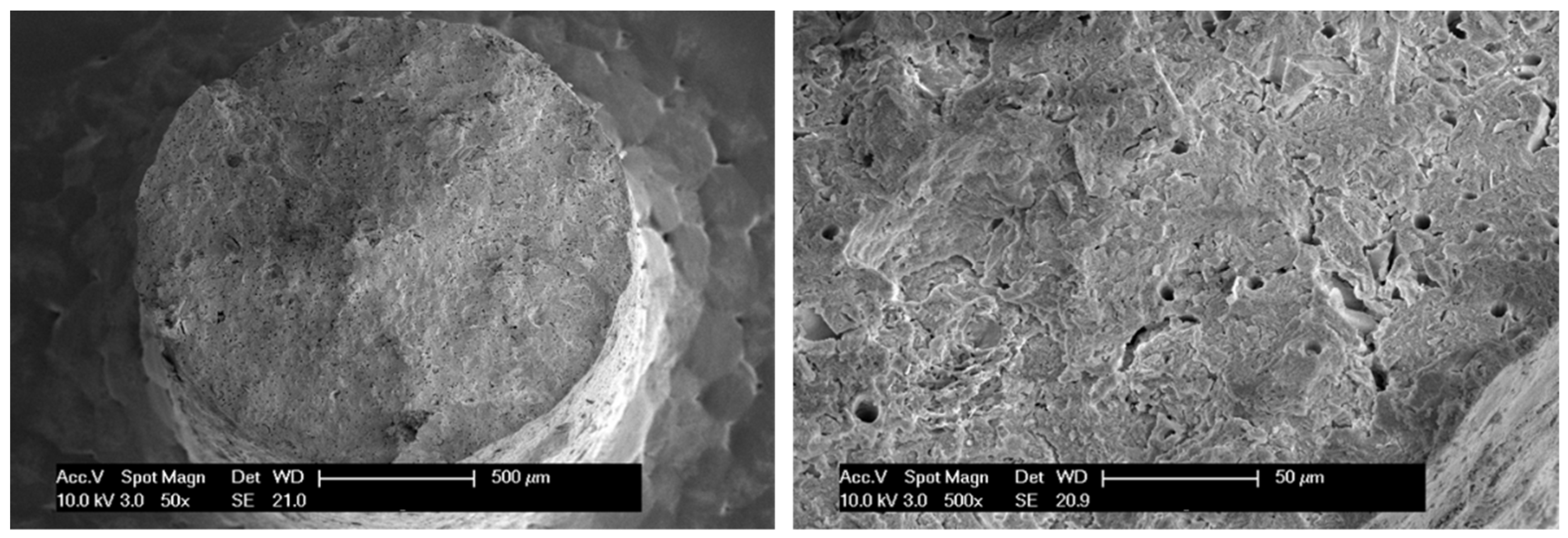
In this case, information from the EPMA analysis and the SEM images is also very important. The distribution of the active metal oxide in the pellet support and the porous texture of the support material may offer some insight into the reaction of gaseous compounds in contact with the solid-state catalyst. Each catalytic reaction in heterogeneous catalysis starts with the adsorption of gases on the catalyst [24]. Therefore, in this case, the catalyst in the support should be loaded into the mesopore, where large tar compounds can migrate and make direct contact with the catalyst. In the case of alumina and montmorillonite extrudate pellets, active metal oxides (Ni, Fe, and Cr) were distributed throughout the complete diameter of the support pellets but were found mainly in the middle of them (see Figure 4). In the SEM images (Figure 5), it can be observed that these support pellets also possess a texture with high porosity in the internal structure of the material. However, on the walls of the pellets, the pores were very small and closed. It was not appropriate for the tar compounds to migrate from the outside to the inside. It would be more likely for them to migrate through the cross-section of the pellets, where more catalyst was deposited. Figure 5 shows the porous textures of the new and the used catalysts. We found that differences in the porosity of the support pellets after naphthalene steam reforming remain nearly unchanged, but the morphology of the material differed from that of the unused catalyst. It is likely that during the reaction, the very fine pores were closed.
The thermal and chemical stability of the montmorillonite itself as an important component of the support and the support with montmorillonite (mixtures at ratios of 60Al/40M, 75Al/25M, and 90Al/10M) was examined. The influence of synthesis gas and organic matter, such as naphthalene, on the support material was investigated. The chemical and thermal stability of the support material is an important basis for each catalyst. From the investigations carried out here, optimal and stable support for the catalyst mixture was found. The mixture of 75% aluminum oxide and 25% montmorillonite remains almost unchanged in its structure during the reaction carried out and is a good catalyst base. An investigation of naphthalene conversion for Cat-Pt on three supports, namely 60Al/40M, 75Al/25M, and 90Al/10M, confirmed that the catalyst on this support works longer and can be regenerated with O2 almost without losses of the specific surface compared to the catalyst on the other support mixtures. The pore size distribution in this case also remains almost unchanged (see Figure 6).
2.1.2. Catalytic Activity
One of the important parameters for evaluating catalyst performance is the light-off temperature, which allows estimation of the temperature range in which the catalyst initiates a catalytic reaction and achieves at least 50% of the reaction conversion. This temperature (T50) is considered to be a characteristic parameter for the particular catalyst and certain reactions that can be initiated with that catalyst. For these experiments, the value of the conversion of hydrocarbons (naphthalene and byproducts that at 250 °C came from naphthalene decomposition) was determined according to the following equation:
where XCH(%) is the hydrocarbon conversion, %; CCH(in) is an upstream hydrocarbon concentration, ppm; and CCH(out) is a downstream hydrocarbon concentration, ppm.
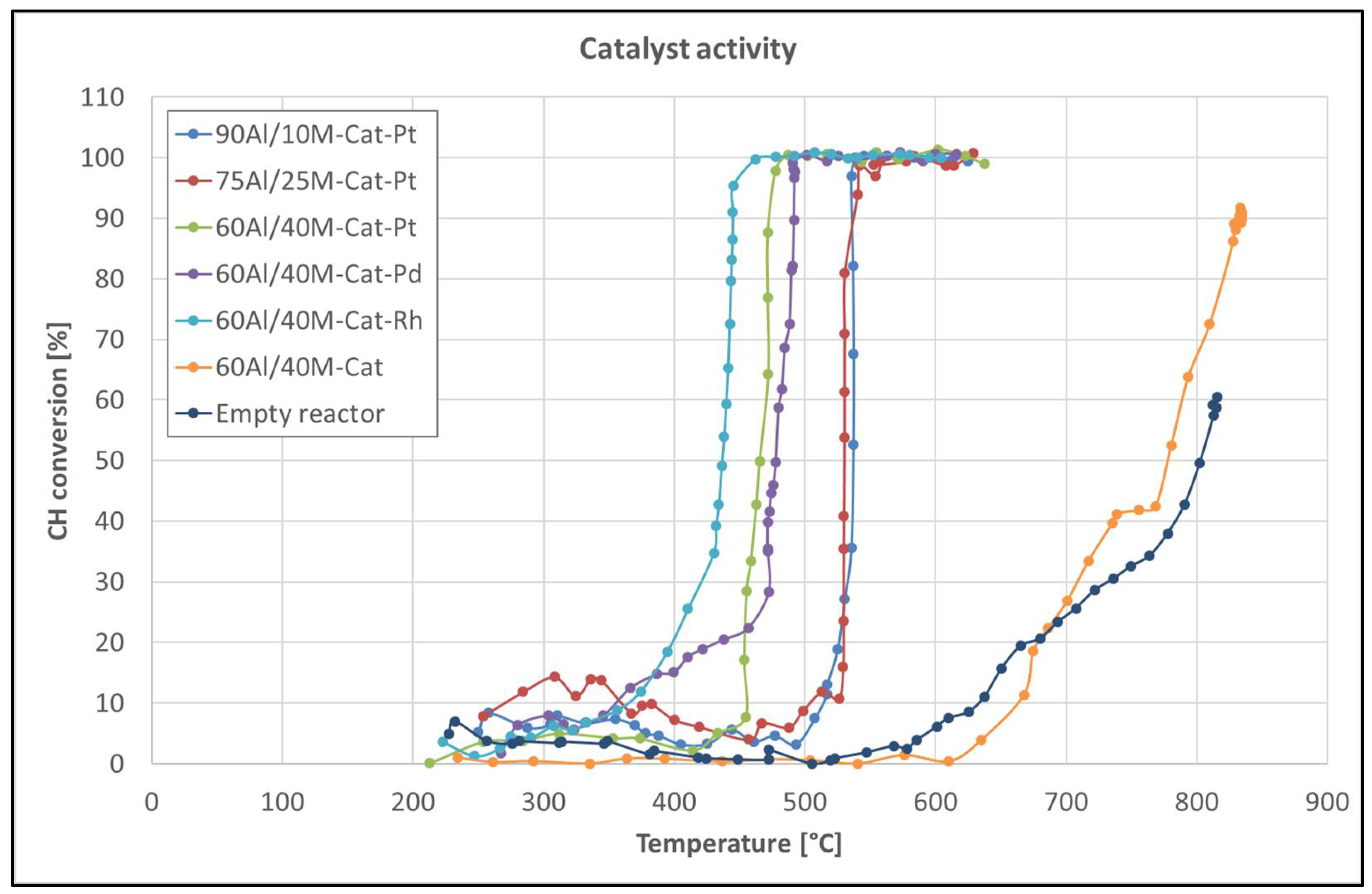
First, we tested what influences different support materials had on the light-off temperature. Support materials are usually inert and do not participate directly in the reaction process, but they are responsible for the interaction between metal supports, which can influence the catalytic reaction [25,26,27]. Figure 7 shows the light-off temperature of the same catalyst on different support materials. Except for the catalyst on the support composition 60Al/40M, all catalysts show a light-off temperature around 530 °C. Only the catalyst on support 60Al/40M seems to be more reactive and reaches its activity at 460 °C. This increase in the catalytic activity can only be related to the montmorillonite content in the support pellets, which also participates in the catalytic reactions. The catalytic activity of montmorillonite is well known [28,29,30], but in this case, a significant catalytic effect could only be observed with the support material containing more than 30% of this mineral.
Second, catalysts promoted with various precious metals and catalysts without a promoter on the 60Al/40M composition of the support pellets were tested to evaluate the effect of the noble metal on the catalytic activity in hydrocarbon conversion (see Figure 7). The influence of the noble metals on the light-off temperature (T50) was obvious. We found that the light-off temperature for the promoted catalysts was 300 °C lower than the light-off temperature of the non-promoted catalyst. In addition, the noble metals in the catalyst distinguish the light-off temperature, but in this case, only a deviation of about 20–40 °C was observed. The noble metal-promoted catalysts may be arranged in the following order according to the increase in the light-off temperature: Rh < Pt < Pd.
All of the catalysts tested were also characterized by a very sharp slope of catalytic activity and reached a 100% hydrocarbon conversion almost at the same temperature as a 50% conversion. The exact values of the light-off temperatures for all the catalysts tested for hydrocarbon steam reforming are listed in Table 1.
For catalysts, not only are the light-off temperatures important but also the long-term effect of the catalytic activity at the desired temperature. Two groups of catalysts were tested for long-term stability in the conversion of naphthalene at a moderate temperature of 580 °C. The influences of the support material and the noble metal on the long-term catalytic activities of the catalysts were investigated. The value of naphthalene (Nap) conversion was determined according to the following equation:
where XNap(%) is the naphthalene conversion, %; CNap(in) is an upstream naphthalene concentration, ppm; and CNap(out) is a downstream naphthalene concentration, ppm.
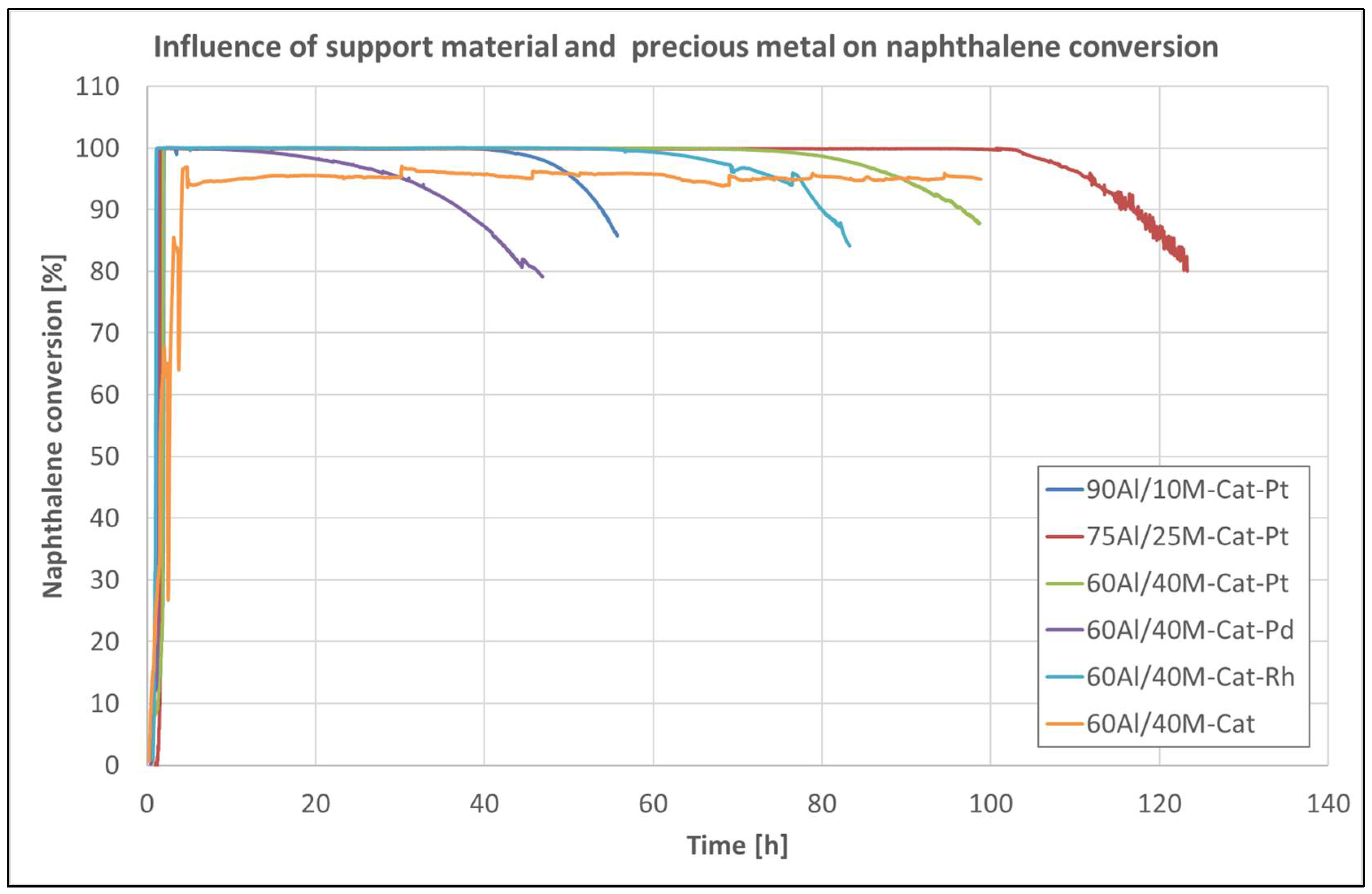
Figure 8 shows the naphthalene conversion over catalysts on various support materials and catalysts with different precious metals as a function of time. It can be seen that the catalyst was deactivated, but at completely different times, depending on the support material on which it was impregnated or on the noble metal used. In this case, the support material itself, or its morphology, influences the deactivation of the catalyst but not the sintering action that can take place inside the catalyst [27]. Coke formation during the reaction is likely responsible for closing the micropores in the support material, which can lead to contact problems between the catalyst and naphthalene. The best porous structure for the catalyst has the support composition 75Al/25M. The catalyst on this material only begins to deactivate after 103 h.
Figure 8 also shows that even the catalysts with different noble metals were deactivated after different times. Only the non-promoted catalyst remained active during the entire measurement time. The Pd-promoted catalyst started to deactivate after 30 h. The Rh-promoted catalyst was more than twice as active, but after about 70 h, it also began to deactivate. The Pt-promoted catalyst remained active for up to 83 h at maximum naphthalene conversion until it began to deactivate. Due to the long-term catalytic activity, the noble metal-promoted catalysts can be assigned in the following order: Pt > Rh > Pd. All tested catalysts, except for the catalyst without noble-metal promoters, were characterized by a sharp and unusual rapid loss of catalytic activity at an operating temperature of 580 °C.
2.1.3. In Situ Regeneration
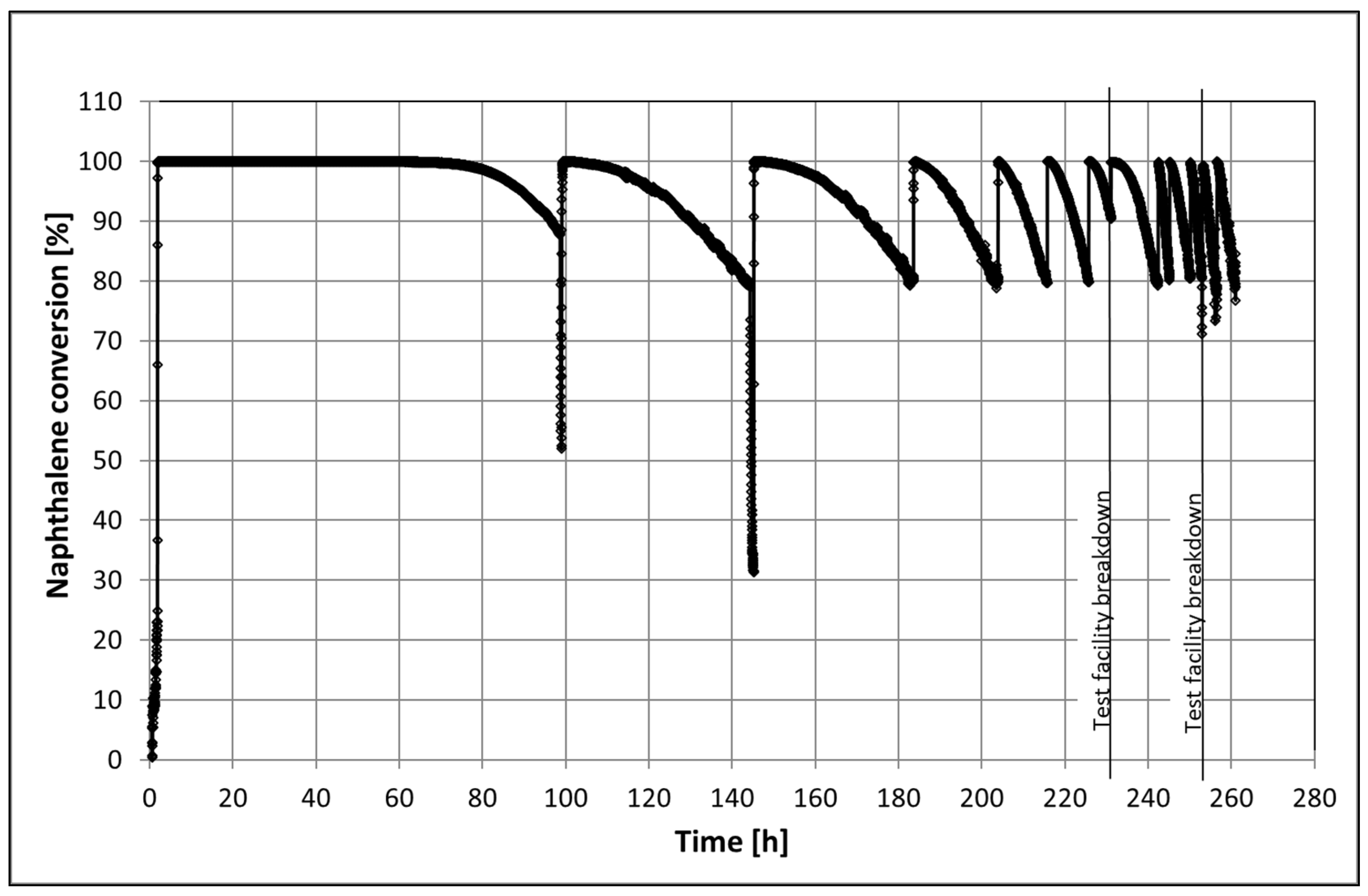
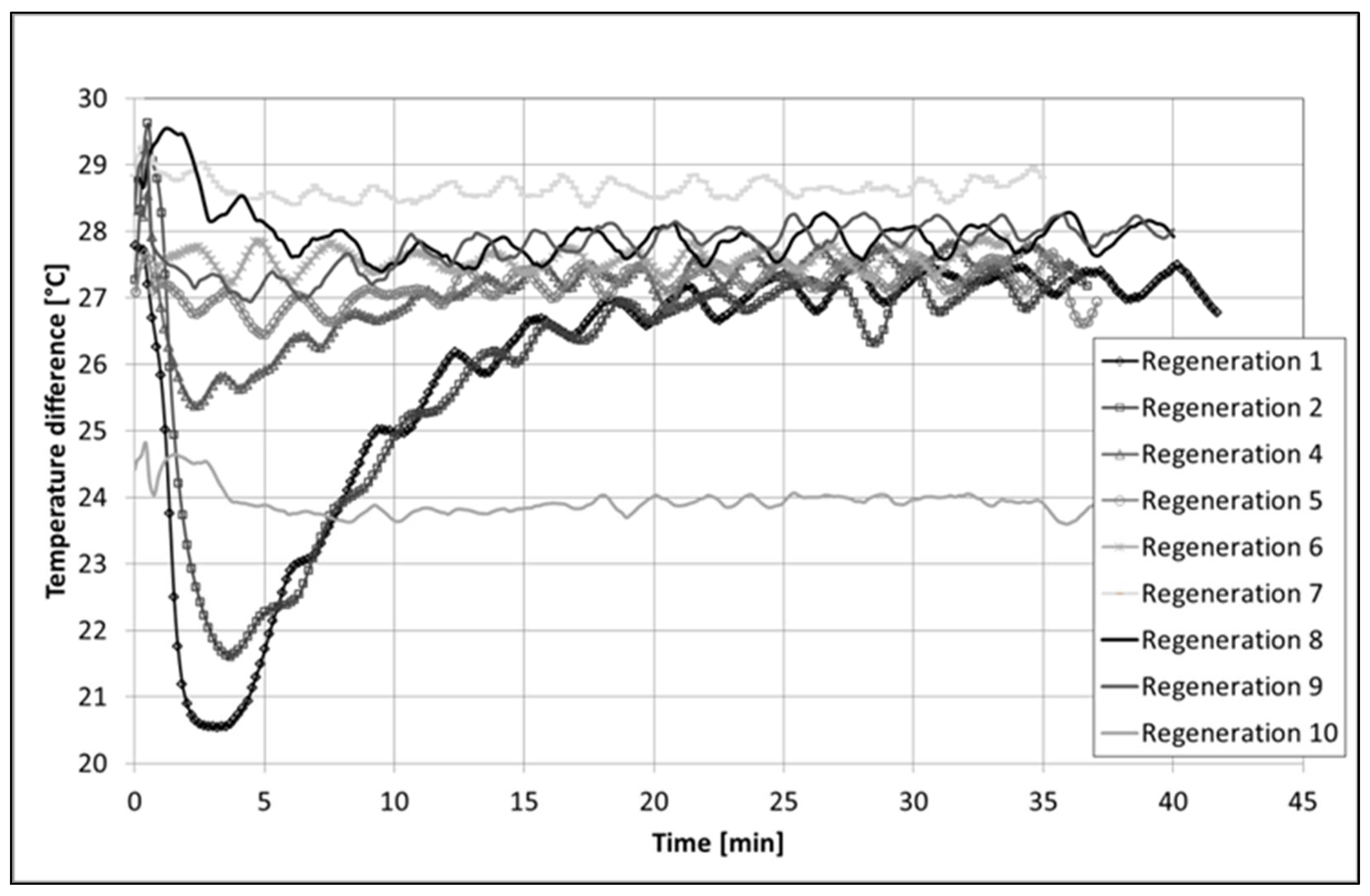
The catalyst 60Al/40M-Cat-Pt was also tested for its long-term catalytic activity at a temperature of 580 °C with in situ regeneration in 10 vol% O2 in approximately 7 vol% H2O steam at 600 °C for 0.5 h. Traces of aromatics, such as xylene, ethylbenzene, and phenol, but no CO2 and CO, were detected in the product gas during regeneration. The catalyst was fully active again and was able to completely convert naphthalene. No complete deactivation of the catalyst was observed, but it was only active for a very short time after the last regeneration (1 h). During that time, the catalyst operated for 260 h, requiring ten regeneration cycles (Figure 9). During regeneration with oxygen, a temperature increase at the catalyst inlet was registered for the first three regeneration cycles (Figure A1). Such an increase in temperature could only be explained by the burning of coke (C(s) + O2(g) ↔ CO2(g); = −394.5 kJ/mol).
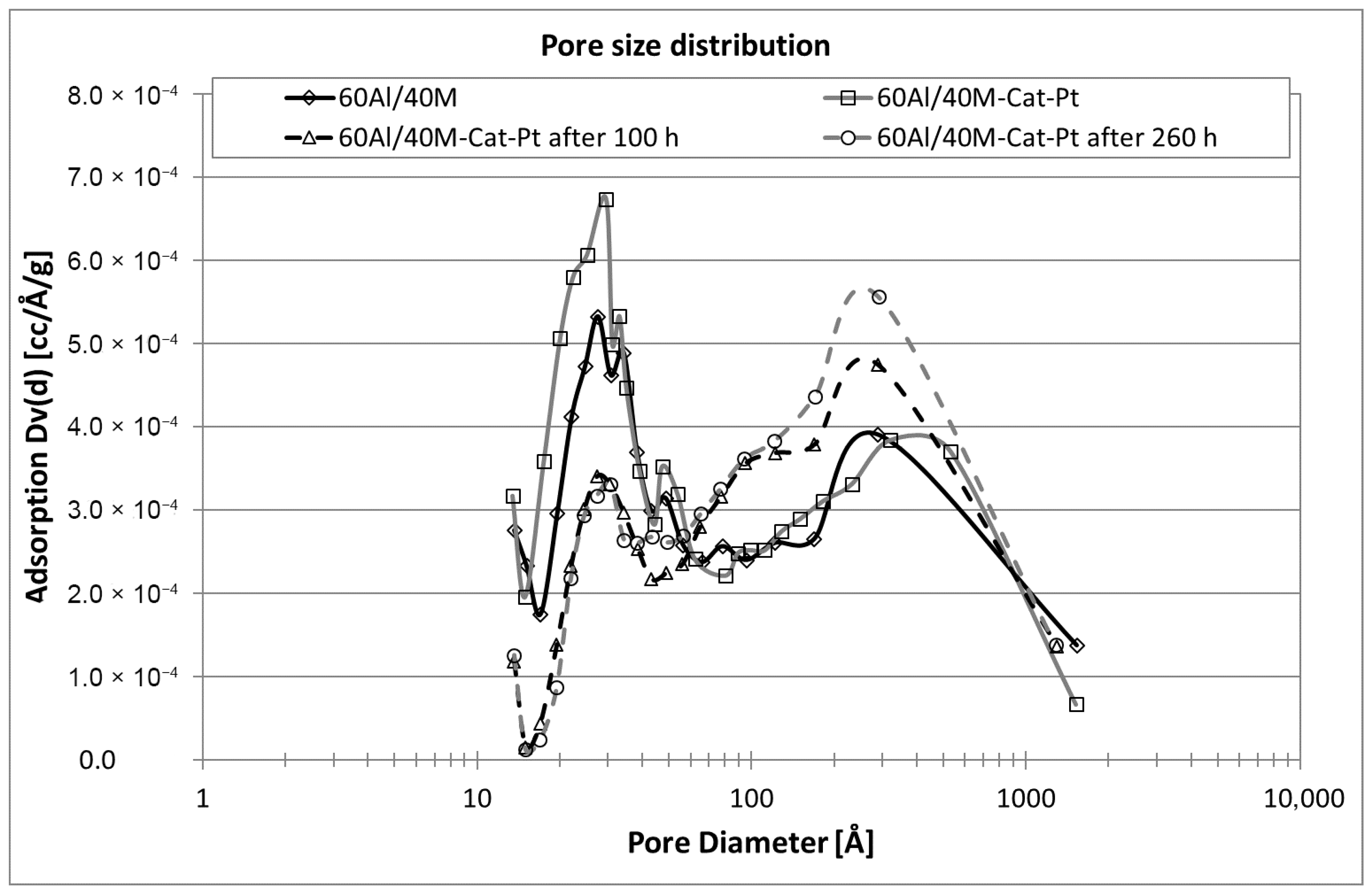
Visually, the catalyst did not change after such a long working time. The pellets’ shape and color remained the same. Nevertheless, the BET analysis (see Supplementary Materials) and SEM image confirmed that changes in the internal structure of the substrate or catalyst occurred. After only 100 h (the first long working time of the catalyst), the specific surface area decreased by 20% (see Table 2). This could be due to the deposition of coke because the catalyst was black-brown before regeneration. However, after the total working time and ten regenerations, the specific surface area was reduced to about 26%, and the catalyst was brown again. In the measurements of the pore size distribution, it was also observed that before the first regeneration, the adsorption in the micropores was significantly lower, while it was larger in the mesopores. When measuring a new catalyst, we observed exactly the opposite (see Figure 10). After the next regeneration cycles, the adsorption in the micropores remained unchanged but increased further in the mesopores. These changes affected the catalyst particles. In that case, metal nanoparticles can spread on the support surface in the micropores, which can lead to an overlap of neighboring particles and eventual particle coalescence [31], or they may be affected by relatively strong metal–support interaction [25]. These changes in the support structure can also be seen in the SEM images. The new catalyst pellets (Figure 5a) have a fine packing structure with many cavities. In contrast, after regeneration, the used catalyst pellet looks like a sticky mass in which many fine pores remain closed (see Figure 11).
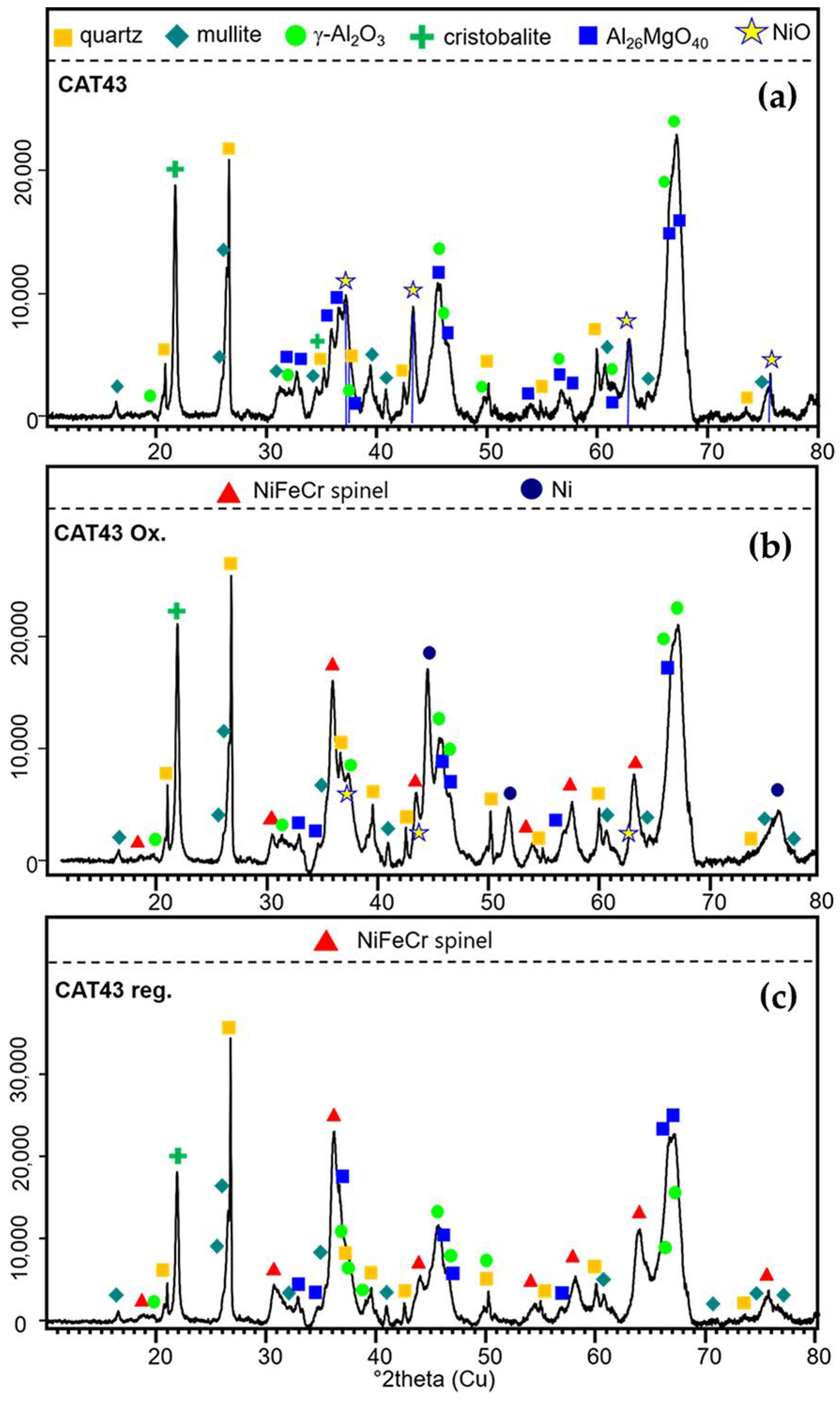
Besides the changes in the support texture that affect the catalyst, changes in the crystal structure of the catalyst were also observed. The XRD pattern of 60Al/40M-Cat-Pt consists mainly of two types of phases (Figure 12a). The first one represents the support matrix and includes quartz, cristobalite, tetragonal alumina: γ-Al2O3, mullite: AlSi1.32O9.66, and Mg-Al oxide: Al26MgO40. The second one, the catalyst, is identified as a NiO (bunsenite), recognizable by its reflections at 2Θ 37.4, 43.2, 62.8, and 75.5°. Phases containing Cr and Pt were not identified in the new catalyst sample. After processing, only slight changes in the phase composition of the support matrix were observed, whereas the formation of new phases containing catalyst elements was observed. After naphthalene reforming (Figure 12b), the presence of elemental Ni could clearly be seen by the reflections at 44.4° 2Θ (111), 51.7° 2Θ (200), and 76.1° 2Θ (220). It cannot be excluded that small quantities of Pt are present because Ni-Pt alloys preserving the Fd¯3m structure (at very low Pt contents) are known [32]. The conversion of NiO catalysts into metallic Ni during propane steam reforming [33] and methane steam reforming [34] is well known. Additionally, in this sample, oxidic Ni, Fe, and Cr are present in phases identified as solid solutions of a spinel-type cubic structure (Fd¯3m) with variable composition. The pure Fe member magnetite possesses a unit cell parameter (u.c.p.) of 8.366 Å. The u.c.p. of Cr2NiO4 (known as nichromite) is 8.299 Å and that of the Cr-free Fe2NiO4 (trevorite) is 8.337 Å. The 50% substitution of Fe by Cr leads to a decrease in u.c.p. to 8.2893 Å in CrFeNiO4 according to Gabal and Angari [35]. Because of the large FWHM (full width at half maximum), it is relatively difficult to determine the real u.c.p., but it seems that a solid solution (i.e., presence of Fe, Ni, and Cr) is most probable. Therefore, we refer to the reflections of these phases as FeCrNi spinel in Figure 12b,c. However, the regeneration of the catalyst with O2 does not lead to the reformation of the active NiO (Figure 12c). In this sample, Ni and Cr together with Fe seem to form a spinel structure once again, probably with an increased Fe content (slight shift of the reflections to lower 2Θ values indicating larger unit cells). This is probably triggered by the mobilization of Fe due to the burning of the coke in an oxygen atmosphere. The fate of platinum during naphthalene reforming and oxygen regeneration could not be entirely determined (beyond possible alloy formation with Ni in the former sample). This is due to the quite low Pt content in the catalyst.
After this unsuccessful regeneration at the operating temperature of 580 °C, the catalyst was repeatedly tested at a high temperature of 795 °C. In this case, the same catalyst, which was no longer catalytically active at 580 °C (naphthalene conversion only 30–40%) showed a further complete naphthalene conversion at a temperature of 795 °C. Based on the new findings, the catalyst was investigated at the same temperature (795 °C) without precious metal. Overall, the experiments were carried out for 280 h without regeneration. After this time, the catalyst still showed a naphthalene conversion of over 90% with little evidence of deactivation. It is likely that only one catalyst component, platinum, was irreversibly deactivated. The transition metal oxides remained active, but higher temperatures are required for naphthalene reforming. It is known that the deactivation of Pt catalysts is strongly influenced by temperature and, to a lesser extent, by the atmosphere [36]. These effects can be attributed to changes in the surface structure caused by adsorbed species, such as H, O, and OH in H2-, O2-, and H2O-containing atmospheres.
2.2. Catalytic Ceramic Filter Material for Tar Conversion
2.2.1. Catalytic Filter Material Morphology
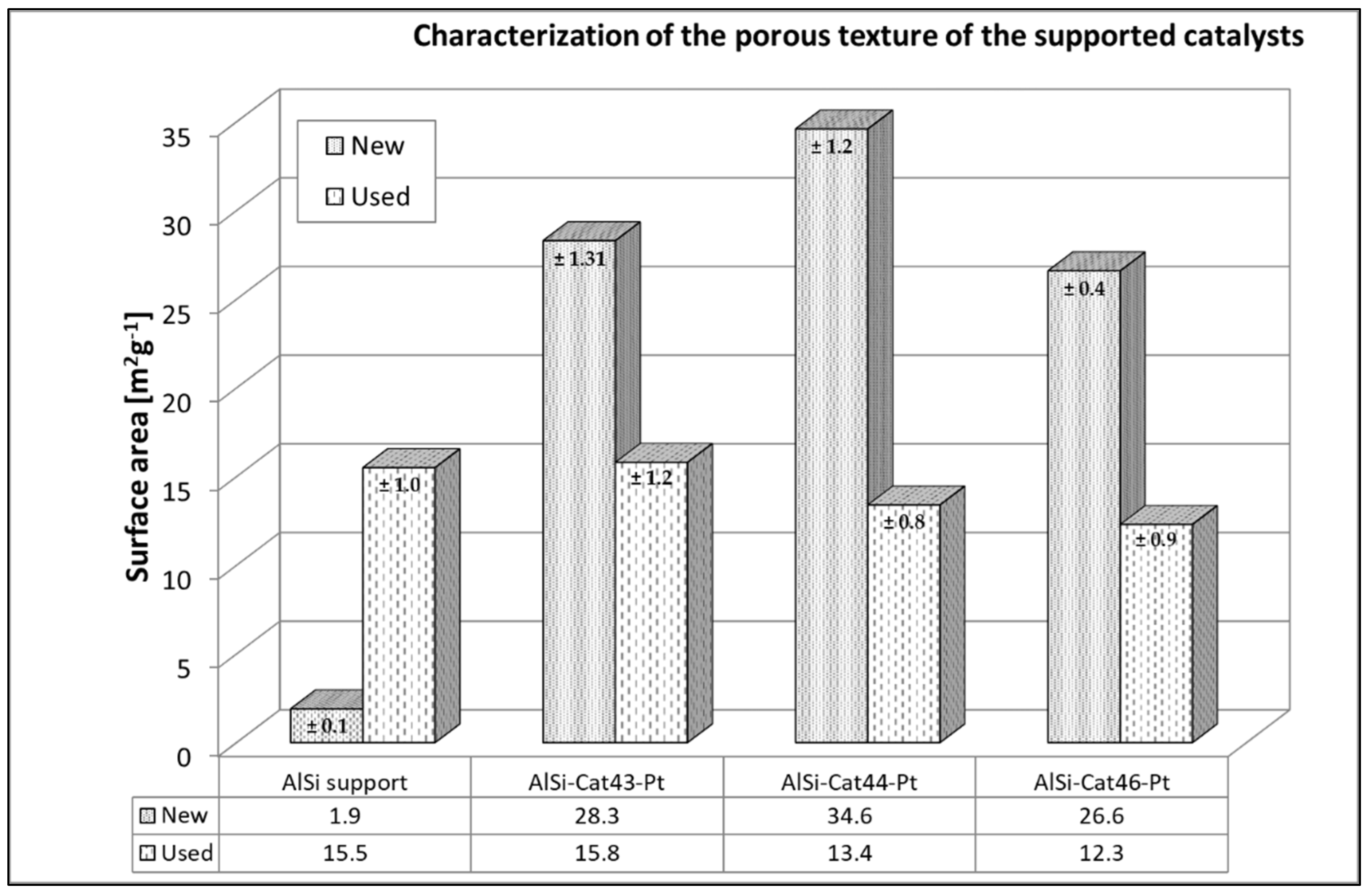
As with the pellet catalyst, the results of the BET surface area also with the ceramic catalytic filter material reflect the adsorption capacities of the respective materials and demonstrate the high affinity of catalysts for tar conversion reactions.
As shown in Figure 13, AlSi-supported catalysts before (New) and after (Used) naphthalene reforming had much lower sorption abilities than those of pellet catalysts. The surface area of AlSi-supported catalysts was approximately 14–18 times larger than that of the pure AlSi support material (1.9 m2/g); however, the AlSi filter material has a higher porosity (80~90%) due to the large distances between the ceramic threads. After the naphthalene reforming, the surface area of the AlSi carrier material increased slightly. The reaction products are probably adsorbed during the reaction [37].
However, after the naphthalene reforming, the specific surface area decreased for all catalysts on AlSi supports. We suspect that coke and byproducts of tar conversion were adsorbed during the process [36,38]. This effect leads to a reduction in the catalyst surface. With regard to the catalytic activity of the catalytic filter elements, the BET surface areas of all the samples were measured and compared. In all cases, a surface reduction of approximately 40% was found after naphthalene reforming, which was twice as high as that of pellet catalysts. These catalytic filter elements also became significantly darker after the reaction, which can indicate coke deposits. Under these conditions, however, reaction products (organic compounds) can also deposit on the catalyst. In the filter material itself, there is much more space between the thread layers of fiber material than in the mesopores of pellet carriers. It is therefore expected that more coke and naphthalene reforming products will be deposited from one side. However, there is also more space for catalyst particles, which can prevent the overlapping of neighboring particles and, ultimately, sintering of the catalyst [31].
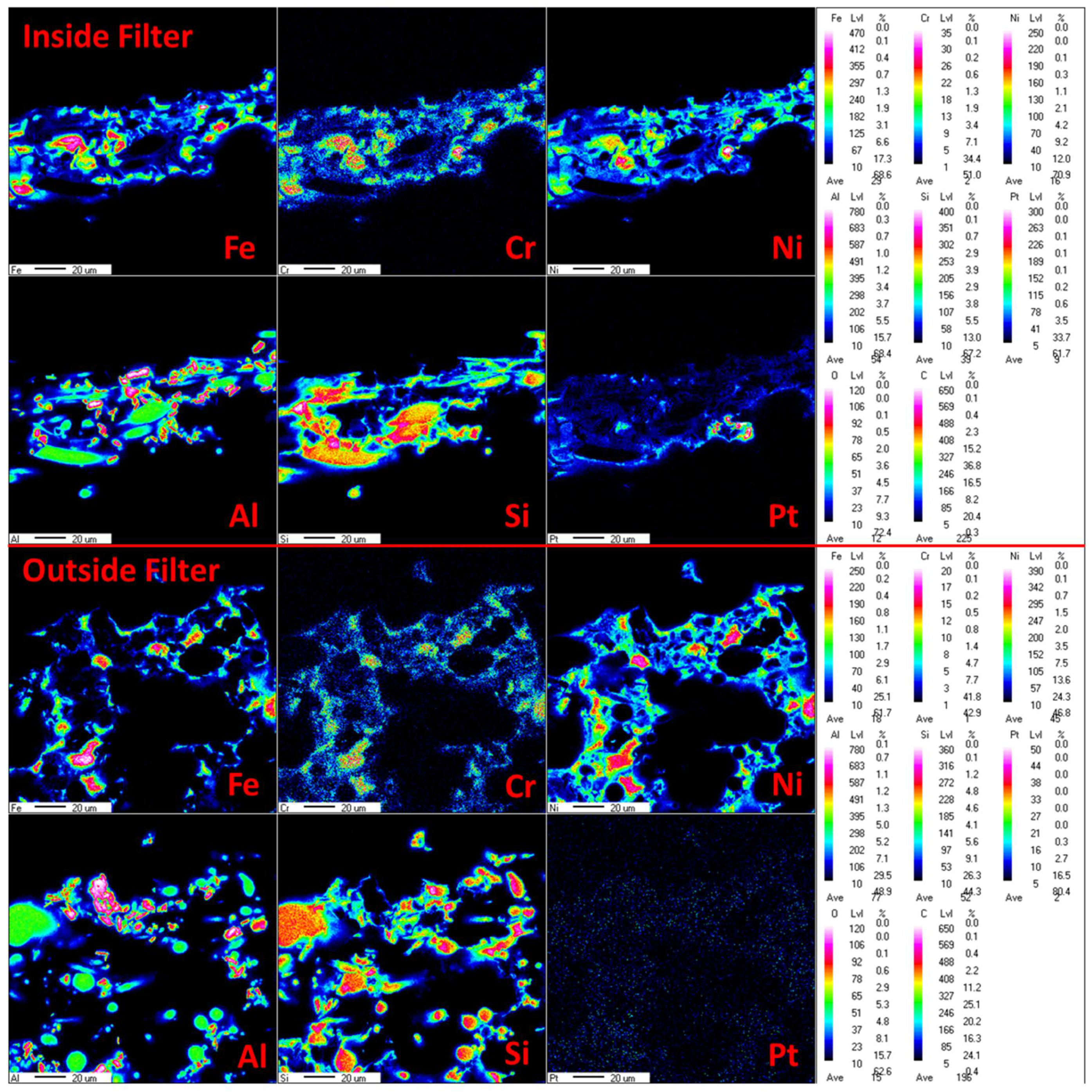
To evaluate the best impregnation method for the catalysts, in addition to the adsorption capacity of the catalyst, the distribution of the catalytic components within the support materials must be analyzed. The distribution of catalyst components on AlSi supports was estimated by means of an EPMA analysis. Each of the catalytic components was uniformly distributed inside the AlSi support material between the threads of the ceramic material. The EPMA analysis was also used to estimate the best conditions for the wet impregnation of the catalyst to achieve the desired effect of more catalyst material on the inside of the filter material. The impregnation of the differently concentrated metal solution with the same amount of metal was investigated. It was found that the impregnation of 10 mL of metal solution leads to the deposition of the catalyst on the filtration side but not on the inside of the filter, where the catalyst was added. It is likely that in this case, the catalytic components along with the solution migrate through all support layers up to the filtration outside. In contrast, the impregnation of 10 mL of metal solution and 30 mL of diluted HNO3 (pH 2) leads to an even distribution of the transition metal oxides in the entire filter material (see Figure 14). This effect can only take place through slow and repeated infiltration of the solution into the filter cross-section. Distributing the catalyst only on the outside of the filter can lead to a very rapid deactivation of the catalyst during operation. In this case, the filter cake of dust and sorbent particles block access to the catalyst [39]. Precious metal, however, which is added during the second impregnation step, is only distributed evenly in the inner part of the filter material. In this way, it is protected from the particles and is freely available for tar compounds. This means that the wet impregnation of the catalyst should be carried out in two steps: in the first step, application of a dilute metal solution with repetition of the impregnation process, and in the second step, application of precious metals to the filter material.
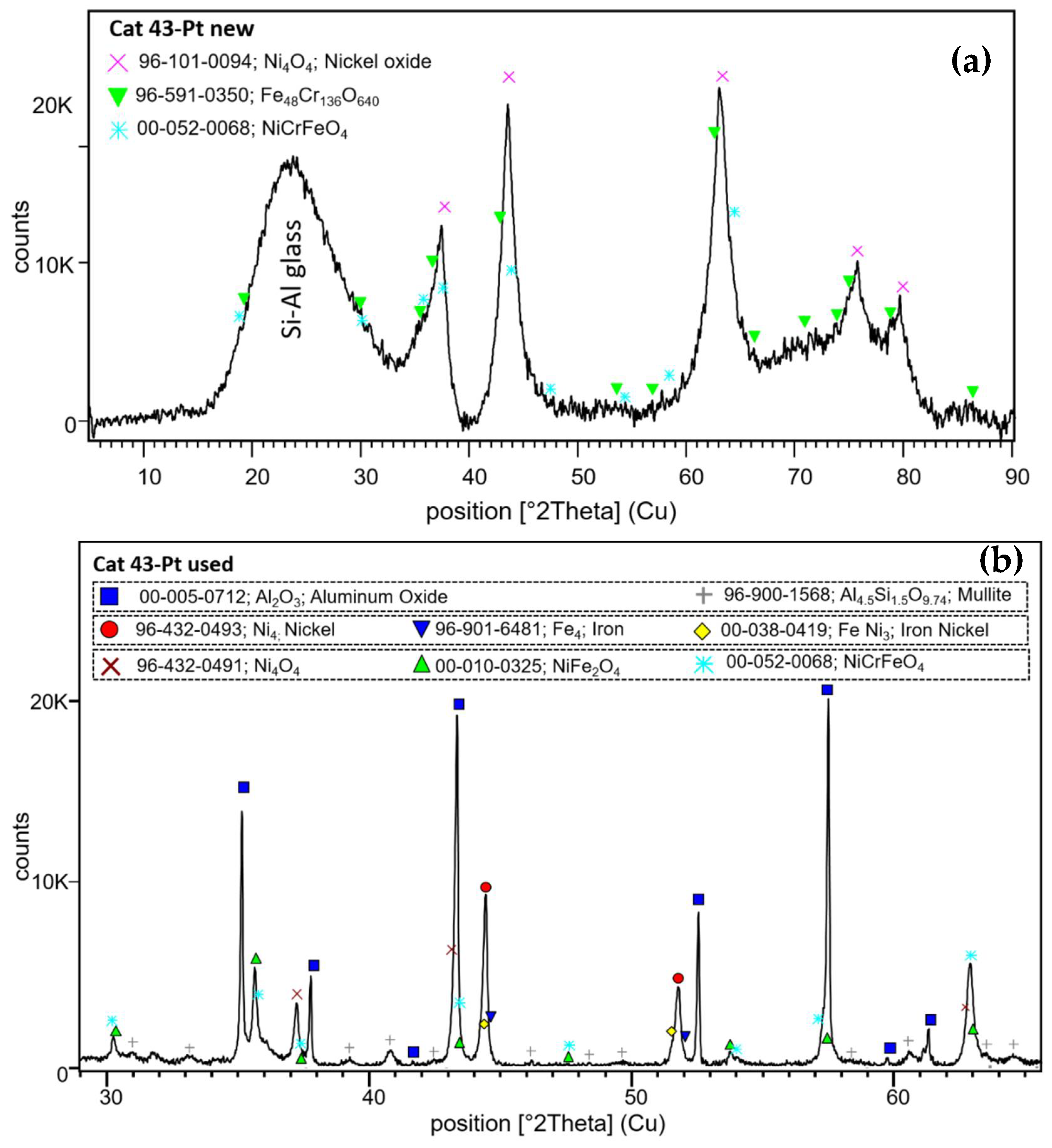
As with the pellet catalyst, the phase of which the active catalyst is made was also examined using X-ray diffraction. Hence, the crystal structures of the new and used Ni, Fe, and Cr catalysts were determined. As we can see in Figure 15, as well as with a catalyst on a pellet support, nickel oxides dominate in the new catalyst. Its reflections are superposed on a broad “hump” centered at 23.6° 2Θ, which is due to amorphous Si-Al glass substrate. The reflections of NiO (bunsenite) are also broad, which indicates a very small crystallite size. In addition to this, an iron-chromium oxide and a Ni-Cr-Fe oxide mixture were identified in contrast to new catalysts on pellet supports. After naphthalene reforming, three main groups of compounds are determined in the XRD pattern: 1) strong reflections of α-Al2O3 accompanied by low intensity mullite peaks, both from the filter material; 2) metallic Ni (2Θ 44.4 and 51.9°) and iron and mixed metals (such as iron-nickel and nickel-chromium-iron); and 3) nickel oxide and various mixed metal oxides forms as NiFe2O4 and NiCrFeO4. Reforming naphthalene will definitely result in oxygen loss in the Ni-, Fe-, and Cr-mixed catalyst and, therefore, active metal sintering, which was also observed with the catalyst on pellets, but metal oxide formation can still occur here despite the long exposure time. In fact, the catalyst can deactivate irreversibly. When reacting with oxygen, the catalyst can only be regenerated if the sintering of the mixed metals has not yet taken place. We previously observed that catalyst regeneration with oxygen does not lead to the formation of NiO again due to the advanced sintering of the catalyst. In addition, due to the low Pt content in the catalyst composition, it was not possible to determine the form in which platinum is present in new and used catalysts.
2.2.2. Catalytic Activity of the Catalytic Filter Material
The catalytic activities of six catalysts on AlSi fiber composite ceramic filter material were examined. The light-off temperatures and long-term activities of these catalysts were determined in, at most, five steps in the case of AlSi-Cat43-PtO and AlSi-Cat43-PtRu catalysts; six steps in the case of AlSi-Cat43-PtORu; and eight steps in the case of AlSi-Cat43-Pt, AlSi-Cat44-Pt, and AlSi-Cat46-Pt catalysts. For these attempts, the hydrocarbon conversion (naphthalene and byproducts) and the naphthalene conversion were determined by taking into account Equations (1) and (2) as in the case of pellet catalysts.
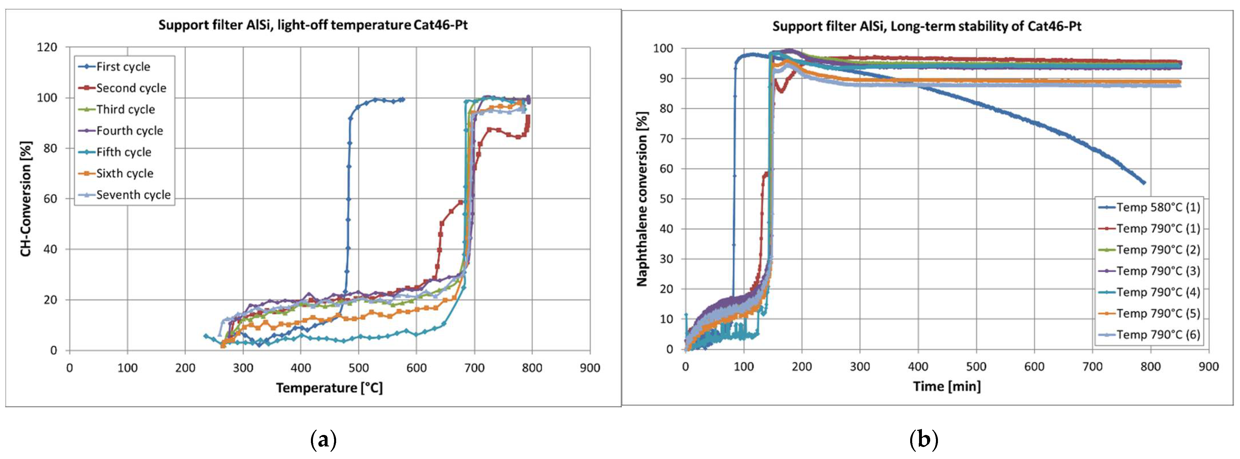
First, the influence of higher amounts of Cr and Mn on the catalytic activity of the filter material was investigated. As expected, these catalytic filter materials (Cat44-Pt and Cat46-Pt) with a new catalyst composition were more active. The effect of shifted light-off temperatures was nevertheless observed (see Figure 16). Regardless of the catalyst composition, the catalysts became catalytically active in the first heating cycle at temperatures from 450 °C to 480 °C. A dominant influence on the catalytic activity of Cr or Mn at the first light-off temperature could not really be seen. However, the changes in the light-off temperatures in the following heating cycle were different for the two types of catalysts. In the case of the catalysts with Cr (AlSi-Cat43-Pt and AlSi-Cat44-Pt), the light-off temperature shifted for each next heating cycle until it stabilized at around 700 °C. In the case of the catalyst containing Mn (AlSi-Cat46-Pt), the light-off temperature increased to a higher temperature by the second heating cycle. During the next tests, it remained almost unchanged at approximately 690 °C. Both types of catalysts were deactivated at the lower temperature of 580 °C, as shown in Figure 16 as an example. The Cr-containing catalysts were less active with a naphthalene conversion (2) of 80%; however, they were still active after 12 h. In contrast, the Mn-containing catalysts were primarily more active with a naphthalene conversion (2) of about 85–95% but lost their activity quickly.
When increasing the reactor temperature to 790 °C, the light-off temperature of all the AlSi-supported catalysts moved (from 449–481 °C) to 653–692 °C, reaching their complete activity again, and the naphthalene conversion rates for AlSi-Cat43-Pt, AlSi-Cat44-Pt, and AlSi-Cat46-Pt repeatedly increased. The same effect was observed with catalysts on a pellet support. The tested 60Al/40M-Cat-Pt catalyst was also deactivated over time at a temperature of 580 °C, but at a higher temperature (795 °C), it was still completely active with a naphthalene conversion of about 95%.
In addition, the Cr-containing catalysts were more active in the long-term activity measurements. The Mn-containing catalyst had the highest naphthalene conversion at the beginning of the experiments but began to deactivate after 80 operating hours.
The reason why the catalysts deactivated after reforming at a lower reaction temperature may be related to Pt deactivation [36,38,40] and residual Ni activity. The deactivation of the platinum was perhaps due to blockage of active Pt sites by the condensation of coke or organic compounds. Takanabe et al. [41] observed the effect of deactivation of a Pt/ZrO2 catalyst in the steam reforming of acetic acid due to the blockage of active sites by the coke/oligomer. Pt can reduce the reforming reaction temperature of catalysts to 460 °C. After the reforming reaction in this experiment, Pt lost its catalytic activity. The reaction temperature increased to approximately 650–690 °C. However, the tar conversion still takes place at lower reaction temperatures as is typical for Ni-based catalysts [42,43].
In the next step, the influence of platinum or platinum–ruthenium on the activity of catalysts impregnated with different solutions was investigated. Again, the light-off temperature and the long-term activity of the catalysts (AlSi-Cat43-PtO, AlSi-Cat43-PtRu, and AlSi-Cat43-PtORu) were measured, and the conversion rates for hydrocarbons and naphthalene were calculated from Equations (1) and (2). The light-off temperature of the tested catalysts in the lower reforming temperature was between 420 °C for AlSi-Cat43-PtORu and 454 °C for AlSi-Cat43-PtRu. However, after 5–6 heating cycles, the light-off temperature of all the catalysts increased to higher temperatures, and in the third heating cycle, all of the catalysts lost their high catalytic activity for CH conversion at lower temperatures. In the case of Pt or Pt-Ru impregnated from aqueous solution, the light-off temperature changed systematically to a higher temperature with each heating cycle. A decrease in the CH conversion at lower temperatures and an increase at higher temperatures were observed continuously. In contrast, the catalysts impregnated with Pt and Pt-Ru from a basic EDTA solution changed their light-off temperature and maximum CH conversion several times between higher and lower temperatures until they stabilized their light-off temperature. In this case, the catalysts AlSi-Cat43-PtO and AlSi-Cat-PtORu appear to be stable at low temperatures but not stable enough.
The light-off temperature changes during heating cycles for all tested catalysts are described in Table 3.
In the course of each heating cycle, the long-term catalytic activities of the catalysts were tested and the naphthalene conversions were measured. Only one catalyst (AlSi-Cat43-PtRu) reached a naphthalene conversion of about 95%, which only slightly decreased (by 15%) in 10 h at temperatures below 600 °C. All other catalysts during the first heating cycle reached a naphthalene conversion of 90%. At a reaction temperature of 790 °C, all catalysts deactivated at lower reaction temperatures and increased naphthalene conversion again during the time of 12 h. The specific maximum naphthalene conversion of the respective catalysts was different.
Concerning the naphthalene conversion and the stability at lower temperatures, the best results were achieved with Pt and Pt-Ru catalysts, which were impregnated from the basic EDTA solution. The second best results were achieved by Pt and Pt-Ru catalysts impregnated from an aqueous solution, with about 10% lower naphthalene conversion.
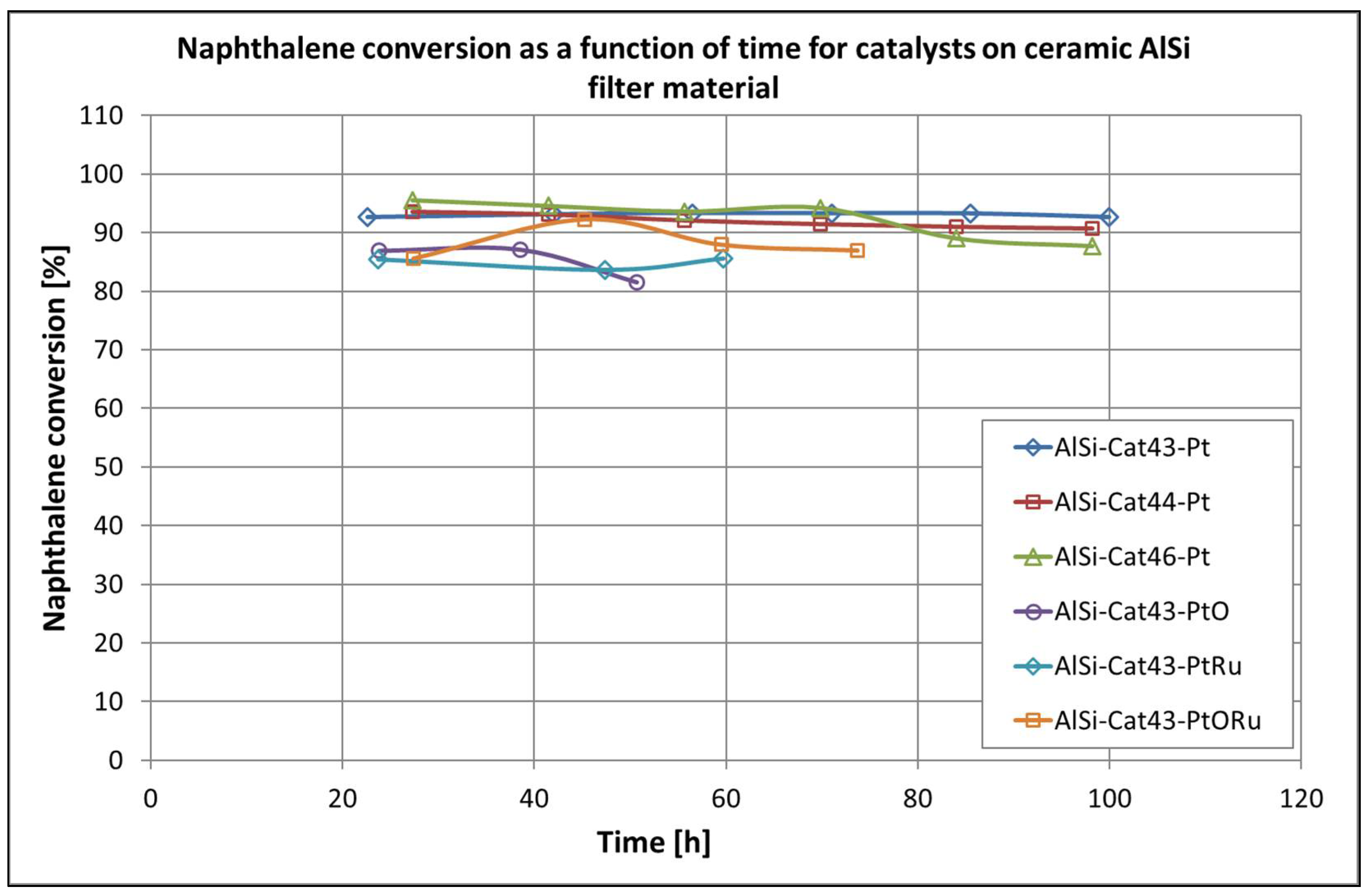
All tested catalysts deactivate after a short period of operation at temperatures below 500 °C. The maximum activity was achieved with all of the investigated catalysts at temperatures around 700 °C. However, comparing the long-term stability data at 790 °C, we can see that the platinum- and catalyst-based compositions with a low Cr content are the most effective (see Figure 17). The addition of ruthenium as the second noble metal increases the naphthalene conversion significantly over the entire temperature range but does not stabilize the activity of the catalysts at lower temperatures. However, this effect is to be expected due to the strong interaction between these two precious metals [44]. Nevertheless, the preparation method of the catalyst affected its reactivity. It was found that the catalysts made from basic EDTA solution were more stable and more active.
2.3. Mechanism of Naphthalene Conversion and Role of the Support Material
This chapter explains a naphthalene decomposition mechanism using our two catalyst systems. However, before analyzing the individual steps, the composition of the decomposition products is evaluated.
In the light-off temperature measurement and long-term measurement of the catalytic activity of all the investigated pelletized-type catalysts, the concentrations of naphthalene and all byproducts were determined (see Figure 18). The course of the concentration curves was the same for all catalysts. In the beginning and before reaching the catalyst activity temperature, only naphthalene and toluene could be measured. Upon reaching the highest activity temperatures, hydrocarbons were converted into CO and probably H2. Unfortunately, H2 could not be measured. As soon as the catalyst begins to deactivate, the concentrations of toluene, naphthalene, and o-xylene in the gas phase rise. Over time, the concentrations of other hydrocarbons, such as benzene, styrene, phenol, and ethylbenzene, also increase. As a result, the CO concentration drops significantly, and the concentrations of CO2 and H2O rise slightly.
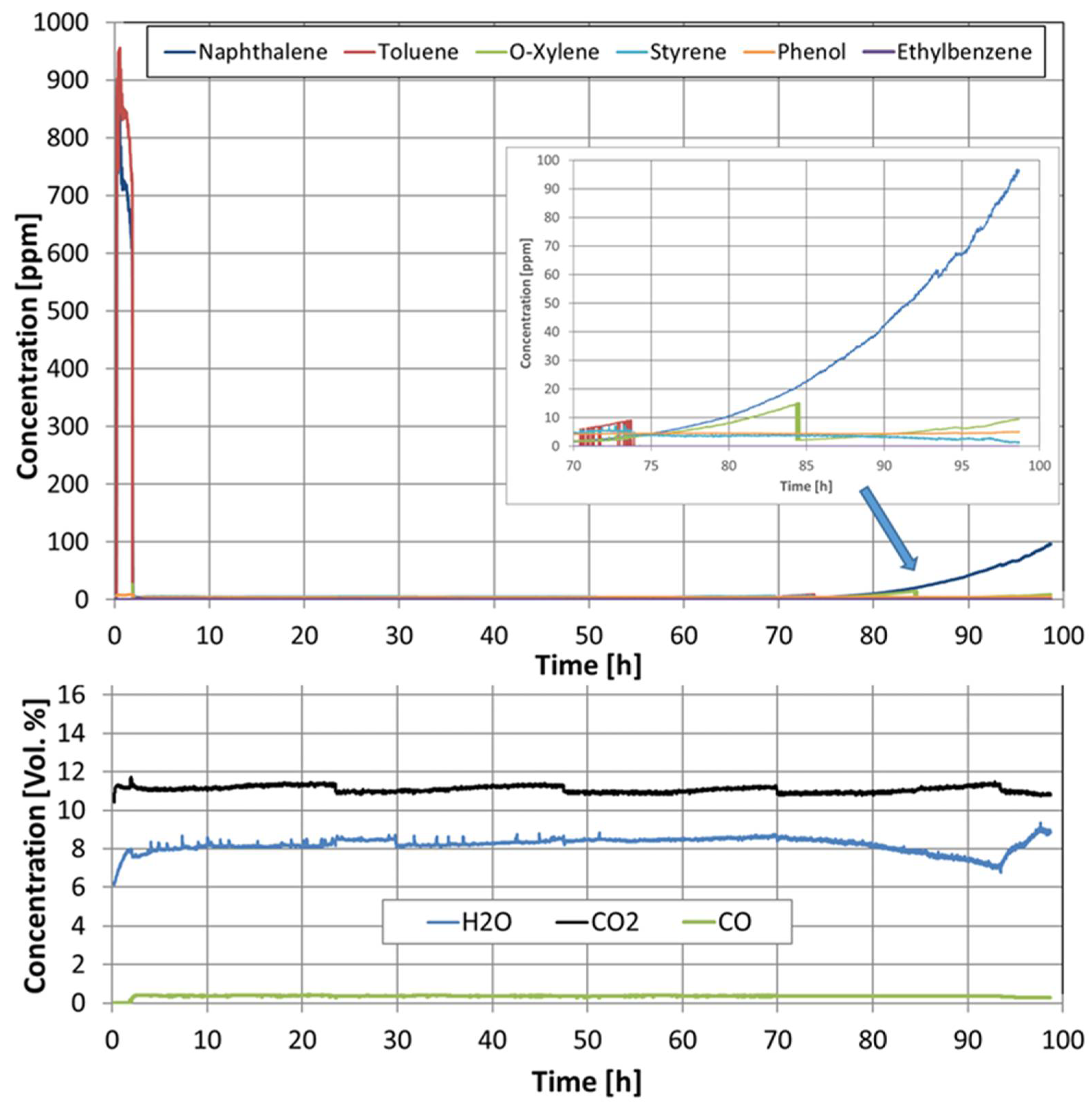
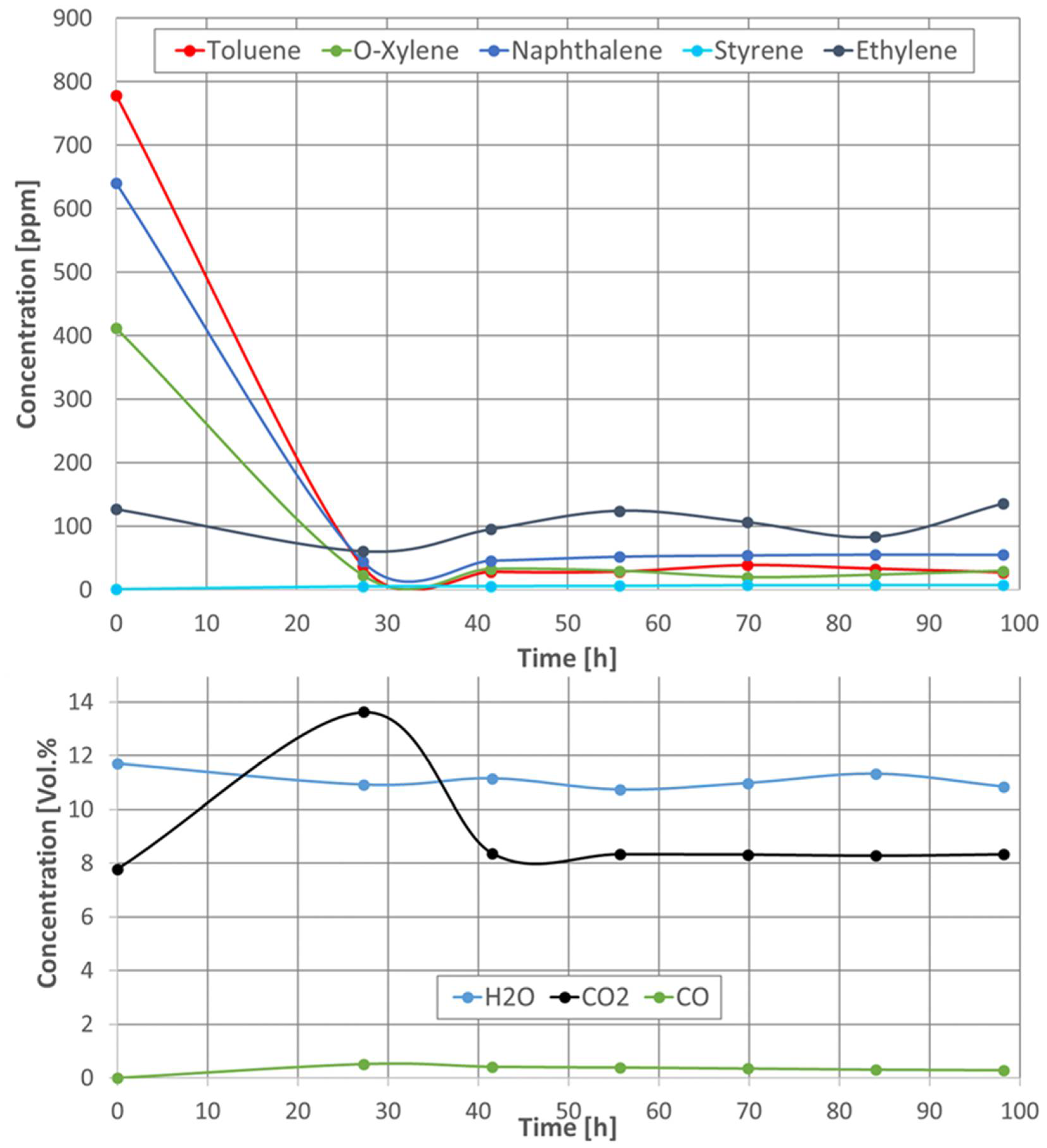
As with the pellet catalysts, the concentrations of all components were measured during the naphthalene reforming of all the tested catalytic filter materials (see Figure 19). Here, too, the same trend of the concentration curves was observed for all catalytic filter materials. At a temperature of 230 °C, i.e., before the catalytic conversion, toluene, naphthalene, o-xylene, and ethylene could be measured. When the catalytic filter materials reached a temperature of 790 °C, not all hydrocarbons were completely converted, as in the case of the pellet catalysts. Toluene and o-xylene remained constant at a concentration between 160 and 10 ppm, depending on the catalyst used. The ethylene concentration also remained almost constant at a level above 120 ppm with the catalytic filter AlSi-Cat46-Pt and dropped to below 100 ppm with the catalytic filter AlSi-Cat43-PtO, AlSi-Cat43-PtRu, and AlSi-Cat43-PtORu during the naphthalene reforming. A significant deactivation of the catalysts AlSi-Cat43-Pt and AlSi-Cat44-Pt during almost 100 h of the measurement time was not observed. However, the CO concentration decreases slightly over time.
We assume that in the first step of the mechanism of naphthalene conversion, which takes place at low temperatures, naphthalene is adsorbed on metal cations via π-electrons either from one or both aromatic rings. This type of adsorption of aromatic hydrocarbons has already been proposed by Trinh et al. [45] in their study on the decomposition mechanism of toluene on Ni (111) and boron-doped Ni (111) surfaces. Our catalyst systems are a mixture of NiO and two or three metal oxide spinels (such as Cr2NiO4, Fe2NiO4, and CrFeNiO4) with oxygen vacancies and offer basic adsorption sites for both π-electron donors and oxygen from H2O and CO2. In the next steps, the hydrogenation, the ring opening by cleavage of the C-C bond, and the formation of ethylene take place. At this point, we can already see what role the support material plays in our two catalyst systems: the pelletized-type catalyst and the catalytic filter material. With pelletized catalysts, where much more acidic sites (Al2O3, montmorillonite) are present in the support material, there are more possibilities for the adsorption of H2O and CO2 or even naphthalene. Adnan et al. [46] observed in their investigation of toluene conversion with Fe2O3/SiO2-doped Al2O3 that the strong acidic sites promote conversion reactivity, which is controlled by the equilibrium between the strong acidic sites and the surface of the catalyst. In the case of steam or dry reforming, this equilibrium between all reactants on the catalysts is very important. Reactions, such as hydrogenation, ethylene formation, and even the conversion of ethylene to CO, can occur faster. Yet, the activation energies in this step of the reaction are not large enough to observe the complete decomposition of naphthalene. Therefore, at the reaction temperature of approximately 230 °C with the pelletized-type catalysts, except naphthalene, only toluene is detected. However, in catalytic filter materials where amorphous aluminum silicate does not yet offer any additional acidic or basic active sites at this temperature, catalysts are less active in all reactions. This is possibly due to a shortage of adsorbed H2O and CO2. Accordingly, naphthalene and toluene are identified at this temperature, in addition to the byproducts o-xylene and ethylene. We suspect that the same reactions take place at higher temperatures, such as adsorption of naphthalene via π-electrons, hydrogenation, cleavage of C-C bonds, formation of ethylene, and ethylene reforming. At a higher temperature, the activation energy for these reactions is large enough for them to occur faster and simultaneously—particularly the hydrogenation and cleavage of the C-C bond. However, due to the support interaction, the pelletized catalysts work much more strongly at higher temperatures and completely convert naphthalene and its byproducts. In the case of catalysts in the catalytic filter material, it is observed that naphthalene and the byproducts, such as ethylene, toluene, and o-xylene, are not completely converted, yet their concentrations remain constant over time. There are not enough active sites in the support material for the adsorption of H2O and CO2. Even though the number of active sites increases with temperature and time due to the crystallization of amorphous aluminum silicate and the formation of α-Al2O3 and mullite (Al4.5Si1.5O9.74), the amount of H2O and CO2 remains insufficient for a complete conversion of all reagents. Therefore, the catalytic filter materials AlSi-Cat43-PtO and AlSi-Cat43-PtORu are also more active in the conversion of byproducts, as they very likely have more oxygen molecules to offer.
At this point, the role of platinum and other precious metals in our catalytic system needs to be discussed in detail. In particular, platinum and other precious metals are known to be the best catalysts for the hydrogenation of unsaturated hydrocarbons at low temperatures. When designing our catalyst system, it was important to us that the naphthalene conversion reaction take place via hydrogenation without undesired side reactions and, above all, at a low temperature as with Ni catalysts. By adding a small amount of precious metal, the catalyst is activated at low temperatures, and naphthalene is partially converted at a temperature of 230 °C. Although the naphthalene decomposition reaction takes place via a hydrogenation reaction, deactivation could not be avoided.
3. Materials and Methods
3.1. Catalyst Preparation
3.1.1. Pellet Catalysts
Each of the different support pellets were prepared by mixing Al2O3 nanopowder 13 nm (Sigma-Aldrich, 99.8%, Steinheim, Germany) and Montmorillonite K-10 (Sigma-Aldrich) with water at three different ratios: 60%/40% (60Al/40M), 75%/25% (75Al/25M), or 90%/10% (90Al/10M). Magnesium oxide (Merck KgaA, Darmstadt, Germany), Charcoal activated (Merck KgaA), and Cellulose microcrystalline (Alfa Aesar, Kandel, Germany) were also mixed in small amounts. Montmorillonite and MgO (0.25 g) were added to ensure support stabilization, whereas charcoal (10 g) and cellulose (5 g) were added to enhance the porosity of the pellets. Small pellets with a diameter of 2 mm were extruded by means of a stamped steel plate on the laboratory mixing and kneading machine (Linden, Marienheide, Germany), dried in air for one day, and then calcined at 950 °C for 12 h. The Ni-based catalysts were prepared by a wetness impregnation of metal nitrates, followed by calcination at 450 °C for 12 h. Initially, the salts of a transition metal, such as Ni(NO3)2·6H2O (55 g, VWR Chemicals 99.9%, Leuven, Belgium), Fe(NO3)3·9H2O (55 g, Merck KGaA 99%), and Cr(NO3)3·9H2O (4 g, Honeywell-Fluka 99%, Seetze, Germany), dissolved in dilute nitric acid (pH 2) were impregnated on the pellets’ extrudate under appropriate stoichiometry. Then, a small amount of salts of precious metal Pt(NH3)4ClH2O (0.3 g, Alfa Aesar 99.9%), Pd(O2CCH3)2 (0.39 g, Sigma-Aldrich 98%), or RhCl3·H2O (0.38 g, Sigma-Aldrich 99.98%) diluted in deionized water was co-impregnated on the prepared before catalysts and then calcined again at 450 °C for 12 h. Two thermal treatments after each impregnation are needed to release nitrates and convert metal salts into metal oxides or metal particles. To be able to distinguish the catalyst samples, they were coded with a combination of the name of the carrier material and the precious metal version as follows: 60Al/40M-Cat-Pt, 75Al/25M-Cat-Pt, 90Al/10M-Cat-Pt, 60Al/40M-Cat-Pd, 60Al/40M-Cat-Rh, and 60Al/40M-Cat.
3.1.2. Catalytic Filter Material
The fiber composite ceramic filter material disc (5 cm diameter, 2 cm thickness) Al2O3(44%)/SiO2(56%) with a porosity of 80~90% and manufactured by Rath (Meißen, Germany) was chosen as support material. In the following, the material is denoted as AlSi. In the first impregnation, metal oxides were created on the filter samples. On one hand, 10 mL of catalytic solution containing 4.95 g Ni (NO3)2∙6H2O (VWR Chemicals, 99%, Leuven, Belgium), 3.6 g Fe (NO3)3∙9H2O (VWR Chemicals, 99.9%), and 0.38 g Cr (NO3)3∙9H2O (Honeywell-Fluka, 99%) and, on the other hand, 3.8 g Cr (NO3)3∙9H2O (Honeywell-Fluka, 99%) or 2.7 g Mn(NO3)2∙4H2O (Alfa Aesar, 99.98%) dissolved in dilute HNO3 (pH 2) were dropped on the surface of filter materials. Whole catalysts were prepared with identical amounts of Ni (7,2 wt%) and Fe (3,6 wt%) oxides. The amount of Mn and Cr was as follows: 0.35 wt% Cr for Cat43, 3.5 wt% Cr for Cat44, and 4.4 wt% Mn for Cat46. After the wet impregnation, each catalytic filter was oven dried at about 90 ℃ overnight and calcined at 450 ℃ for 12 h. In the next step, noble metal was impregnated on the filter. Pt or Pt-Ru in water solution or basic EDTA solution (0.1 g EDTA in 0.1 mol/l NaOH), which contained 25 mg Pt (NH3)4∙Cl2∙H2O (Alfa Aesar, 99.9%) and/or 40 mg [Ru(NH3)6]∙Cl2 (Alfa Aesar, 99.9%), was applied to each sample. The percentage of Pt/Ru in the solution was up to 0.2 wt%. Then, drying and calcining were carried out under the same conditions as above. To be able to differentiate between the catalyst samples, they were coded with a combination of the name of the carrier material, the number of the catalyst solution, and the precious metal version as follows: AlSi-Cat43-Pt, AlSi-Cat44-Pt, AlSi-Cat46-Pt, AlSi-Cat43-PtO, AlSi-Cat43-PtRu, and AlSi-Cat43-PtORu.
3.2. Catalyst Characterization
The physicochemical properties of the prepared pellets and ceramic filter material catalysts were characterized before and after reaction by BET (Brunauer–Emmett–Teller) physio-sorption, pore size distribution, SEM (scanning electron microscopy), and X-ray diffraction. Selected specimens of the catalysts were also investigated with an electron probe micro analyzer (EMPA) (JXA-8530F hyperprobe, JEOL, Tokyo, Japan). The specific surface area was determined by BET analysis (ChemiSorb 2750, Micromeritics, Unterschleißheim, Germany) using a single-point determination in a gas mixture of 30% N2–70% He. Three nitrogen adsorption–desorption cycles were performed for each catalyst sample, and the final surface area was calculated as an average value. The pore size distributions (BJH method) of the catalyst were determined with a Quantachrome Autosorb-1 instrument by adsorption measurements with nitrogen at −196°C. SEM studies were performed in a Philips XL 30 ESEM analyzer (Eindhoven, The Netherlands), specifically for the observation of sintering effects in the pellet support material during the reaction. The catalyst samples were also investigated by X-ray diffraction using MPD Xpert-pro (PANalytical, Almelo, Netherlands) equipped with a multistrip PIXell detector (255 channels, 3.347°2Θ) and Cu radiation. Cu-Kβ was filtered with a Ni filter. The measurements were taken with Soller slits 0.04 rad (2.3°) and adjustable slits giving a constant irradiated sample length of 10 mm. For phase identification, the software packages Highscore-Plus (PANalytical) and Diffrac-Plus (Bruker-AXS, Karlsruhe, Germany) were used. To investigate the catalysts’ distribution on the support pellets or the ceramic filter material for the same samples, EMPA analyses were performed in a JOEL JXA-8530 F analyzer.
3.3. Catalyst Activity
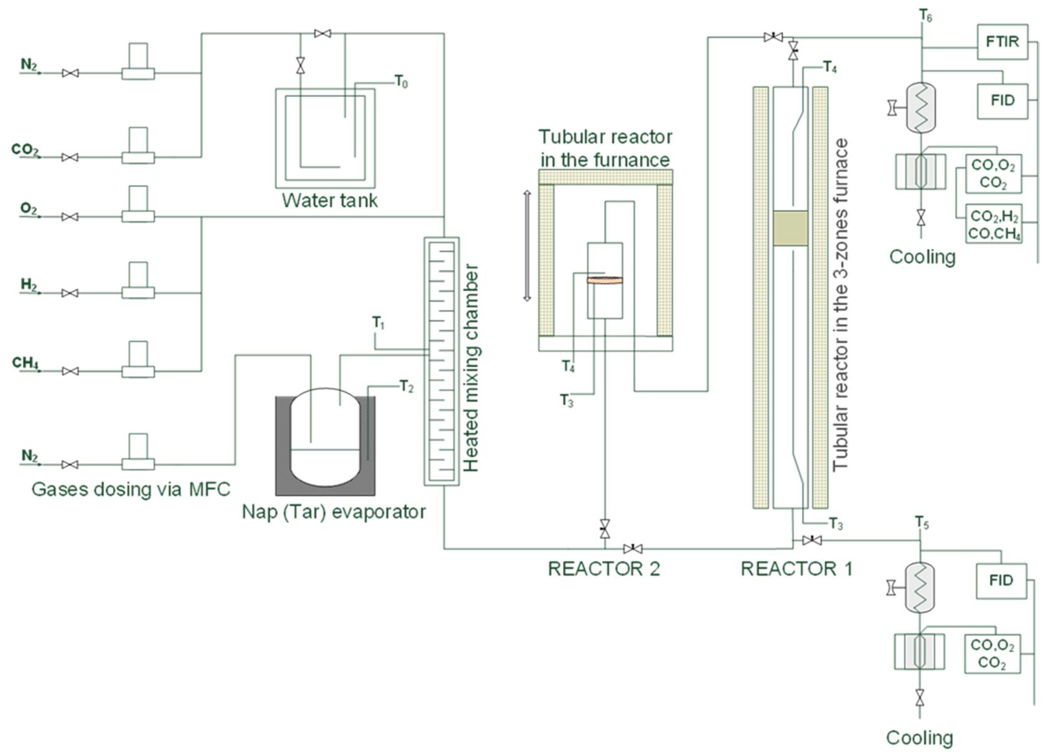
The catalytic tests were performed in two reactors (see Figure 20). In REACTOR 1, the catalyst pellets (60–65 g) were fixed in a tubular stainless steel fixed-bed reactor (120 cm long, 5 cm in diameter) between two circular fine steel grates and heated to the required temperature in the three-zone oven. The total gas flow rate for these tests was 0.50 Nm³/h at a space velocity (GHSV) of 5000 h−1. In REACTOR 2, the catalytic filter disc with a filter area of 12.6 cm2 was placed inside of the tubular reactor (20 cm height, 5 cm in diameter) with the appropriate sealing materials (Isoplan 1000), fixed in the flange, fastened to the tube reactor, and mounted inside the hood furnace. The total gas flow rate for these tests was 0.33 Nm³/h at a space velocity of 8400 h−1. The composition of the inlet gas was as follows: 10 vol% CO2, 10 vol% H2O, and 0.15 vol% naphthalene as model tar compounds and 79.85 vol% N2 as a carrier gas for steam and naphthalene. In both experiments, digital mass flow controllers (MFCs) (Bronkhorst) provided the gases, and their composition was reviewed and adjusted by the system design software LabVIEW. The addition of steam to the gas stream was carried out by saturating the gas in an electrically heated water tank maintained at 58 °C. Naphthalene was added by passing a stream of nitrogen through a heated tube containing a solid compound immersed in an oil bath at a constant temperature of 90 °C. All incoming gases, the N2 flow containing naphthalene, and the gas stream from the water tank (N2, vapor, and CO2) joined up in a mixing chamber and were pre-heated to 190 °C. In both reactors, the temperature was measured by two thermocouples on the top and bottom of the catalyst bed or catalytic filter material. In addition, the pressure difference between the upstream and downstream of the catalyst bed or catalytic filter material was continuously measured in both reactors. To avoid condensation of the naphthalene and its decomposition products, all of the pipework was heated in a controlled manner (standard heaters: WiNKLER AG (Heidelberg, Germany), IsoPad THERMOCOAX (Heidelberg, Germany), HORST (Hillesheim, Germany)) or covered with thermal insulation materials. Both raw and reformed gases were analyzed by an online modular detection system. The complete concentration of hydrocarbons was determined with a flame ionization detector (FID, Ultramat 5, Siemens (Karlsruhe, Germany)). CO, CO2, and O2 were measured after cooling in the cooler EC (M&C) with an infrared analyzer (IR Ultramat 23, Siemens). The concentrations of detectable organic and inorganic compounds after the reforming reaction were measured using a Fourier transform infrared spectrometer analyzer (FTIR, Gasmet Technologies (Vantaa, Finland)) using the software Calcmet (Gasmet Technologies).
3.4. Catalytic Test Performance
Both the catalysts on the pellet supports and the catalysts on the ceramic filter material were tested in two types of experiments: catalyst light-off temperature and long-term catalytic activity. To investigate the light-off temperature of the catalyst, the tests were carried out during the ramping phase from 250 °C to 630 °C or 835 °C (set temperature) with a pellet catalyst or at 300 °C to 650 °C or 850 °C (set temperature) with a catalytic filter, both at 3 °C/min. To investigate the long-term catalytic stability of the catalytic materials, the tests were carried out at a constant temperature of 650 °C or 860 °C (set temperature) until the pellet catalyst was deactivated or for 9–12 h in five or eight heating cycles to prove the catalytic filter.
The long-term catalytic activity tests with in situ regeneration were carried out for pellet catalysts at a constant temperature of 650 °C (set temperature) until the catalysts deactivated or reduced the naphthalene conversion by about 20%. After this time, the in situ regeneration of the catalyst took place. The 60Al/40M-Cat43-Pt was regenerated under the following conditions: 10% O2, 6.9% H2O at 600 °C during 0.5 h. After regeneration, the catalytic activity of the catalyst was retested until the naphthalene conversion decreased by about 20%. Then, the catalyst was regenerated again.
4. Conclusions
In downstream hot gas cleaning, catalytic gas conversion takes place at the end of the overall system and has to be adapted to the system. Therefore, in this work, Ni-based and precious metal-promoting catalysts were designed and produced on two types of support materials due to their application in two different hot syngas cleaning systems.
A special pellet catalyst was developed for hot gas cleaning with a separate fixed-bed stage. The extrudates of Al2O3 and montmorillonite mixtures with different stoichiometries were investigated. The mixture of 75% aluminum oxide and 25% montmorillonite with a lower surface area of up to 65 m²/g was found to be optimal as a support for catalysts. After the first long-term naphthalene oxidation, all tested catalysts lost their initial specific surface areas, which decreased by about 15–20%. The EMPA and XRD analyses showed that the distribution, localization, and crystal structure of the catalyst in the porous material of the pellet influence the activity of the catalyst. The two parameters light-off temperature and the long-term catalytic stability were examined for all of the produced catalysts. Rh- and Pt-promoted catalysts on the 60Al/40M pellets demonstrated the best performance with respect to the light-off temperature and achieved complete naphthalene conversion at 445 and 470 °C, respectively. However, the Pt-promoted catalyst on the 75Al/25M pellet extrudate achieved the best long-term catalytic stability, which was active for up to 103 h and completely converted the naphthalene at 580 °C. The catalysts tested were suitable for complete naphthalene conversion but were deactivated at temperatures below 600 °C after an operating time of approximately 100 h. With ten in situ regeneration cycles with oxygen, an extended catalyst operating time of up to 260 h was possible, but the catalyst was only active for a short time (1 h). It was also demonstrated that the slight coking of the catalyst under the given reaction conditions does not lead to the deactivation of the catalyst but rather to irreversible poisoning as a consequence of the sintering of the noble metal.
A special catalytic ceramic fiber filter was developed for compact catalytic hot gas cleaning systems with entrained-flow sorption. The wet impregnation process of the dilute catalyst metal solutions was proven to be the best method for implementing catalysts in AlSi fiber composite ceramic candles. At low temperatures, i.e., below 600 °C, all supported AlSi catalysts were only active for about 20 h and were able to decompose naphthalene to 50%. The catalytic activity increased significantly at temperatures around 700 °C. For example, the AlSi-Cat43-Pt catalytic filter was able to convert 93% of the naphthalene in at least 100 h and the AlSi-Cat44-Pt catalytic filter was able to convert 91% in 98 h. In both cases, no deactivation was observed. By adding ruthenium as the second noble metal, it was possible to increase the catalytic activity of the naphthalene conversion catalyst at temperatures of around 700 °C. Experiments in which the reactivity of the catalyst was influenced by the catalyst preparation method were also carried out. It was shown that the catalysts in which noble metals were prepared in the second impregnation step with an EDTA base solution were more stable in the relevant temperature range.
The mechanism of the decomposition of naphthalene via the adsorption of naphthalene π-electrons from one or two aromatic rings to metal cations and parallel rapid reactions, such as hydrogenation, cleavage of C-C bonds, formation of ethylene and ethylene reforming, was proposed based on the concentrations of byproducts. The implementation of small amounts of the noble metal in the Ni-based catalyst is necessary to achieve operating temperatures for the tar reforming reaction well below 800 °C.
Supplementary Materials
The following are available online at https://0-www-mdpi-com.brum.beds.ac.uk/article/10.3390/catal11101231/s1, Figure S1: Results of BET measurements of the 60Al-40M-Cat-Pt, Figure S2: Results of BET measurements of the 60Al-40M-Cat-Pt after 100 h, Figure S3: Results of BET Measurements of the 60Al-40M-Cat-Pt after 260 h, Figure S4: Results of BET measurements of the 75Al-25M-Cat-Pt, Figure S5: Results of BET measurements of the 90Al-10M-Cat-Pt, Figure S6: Results of BET measurements of the 60Al-40M-Support, Figure S7: Results of BET measurement of the 75Al-25M-Support, Figure S8: Results of BET measurement of the 90Al-10M-Support, Figure S9: Results of BET measurement of the regenerated 75Al-25M-Cat-Pt, Figure S10: Results of BET measurement of the used 75Al-25M-Cat-Pt.
Author Contributions
G.S. designed and performed part of the experiments, analyzed the data, and wrote the paper; R.M. designed part of the experiments; U.G. contributed with the EPMA microscopy data; K.G. performed the X-RD measurements and analyzed the data; H.L. contributed to the discussion and reviewed and supervised the work. All authors have read and agreed to the published version of the manuscript.
Funding
This research was supported by the Technology Transfer Project N023 of the Karlsruhe Institute of Technology and the EU project “HiEff BioPower” of the European Union Horizon 2020 Program under Grant Agreement no. 727330.
Acknowledgments
The authors would like to especially thank Herbert Fischer for sample preparation and the SEM measurements, Oliver Görke for the determination of the pore size distribution with the BJH method, and Florian Messerschmidt for sample preparation for the EPMA investigation.
Conflicts of Interest
The authors declare no conflict of interest.
Appendix A
During in situ regeneration of the pellet catalyst 60Al/40M-Cat-Pt, the temperature above and below the fixed bed of the catalyst was measured. The observed increase in temperature can only be indicated by the reaction with oxygen during coke combustion, which, in our experiment, only takes place in the first three regeneration cycles.
Figure A1.
Change in the temperature difference between inlet and outlet of the catalyst bed during regeneration with 10% O2 in 7% steam as a function of time.
Figure A1.
Change in the temperature difference between inlet and outlet of the catalyst bed during regeneration with 10% O2 in 7% steam as a function of time.

References
- Hasler, P.; Nussbaumer, T. Gas cleaning for IC engine applications from fixed bed biomass gasifications. Biomass Bioenergy 1999, 16, 385–395. [Google Scholar] [CrossRef]
- Zhang, W.; Liu, H.; Ul Hai, I.; Neubauer, Y.; Schröder Ph Oldenburg, H.; Seilkopf, A.; Kölling, A. Gas cleaning strategies for biomass gasification product gas. Int. J. Low-Carbon Technol. 2012, 7, 69–74. [Google Scholar] [CrossRef]
- Zwart, R.W.R. Gas Cleaning Downstream Biomass Gasification; Status Report; (ECN-E-08-078); Energy Research Center of the Netherlands (ECN): Petten, The Netherlands, 2009; pp. 1–65. [Google Scholar]
- Myren, C.; Hörnell Ch Björnbom, E.; Sjöström, K. Catalytic tar decomposition of biomass pyrolysis gas with a combination of dolomite and silica. Biomass Bioenergy 2002, 23, 217–227. [Google Scholar] [CrossRef]
- Devi, L.; Ptasinski, K.; Janssen, F.; van Paasen, S.; Bergman, P.; Kiel, J. Catalytic decomposition of biomass tars: Use of dolomite and untreated olivine. Renew. Energy 2005, 30, 565–587. [Google Scholar] [CrossRef]
- Devi, L.; Craje, M.; Thüne, P.; Ptasinski, K.J.; Janssen, F.J.J.G. Olivine as tar removal catalyst for biomass gasifiers: Catalyst characterization. Appl. Catal. A Gen. 2005, 294, 68–79. [Google Scholar] [CrossRef]
- Rapagn, S.; Jand, N.; Kiennemann, A.; Foscolo, P.U. Steam-gasification of biomass in a fluidised-bed of olivine particles. Biomass Bioenergy 2000, 19, 187–197. [Google Scholar] [CrossRef]
- Swierczynski, D.; Libs, S.; Courson, C.; Kiennemann, A. Steam reforming of tar from a biomass gasification process over Ni/olivine catalyst using toluene as a model compound. Appl. Catal. B Environ. 2007, 74, 211–222. [Google Scholar] [CrossRef]
- Wang, T.J.; Chang, J.; Wu, C.Z.; Fu, Y.; Chen, Y. The steam reforming of naphthalene over a nickel–dolomite cracking catalyst. Biomass Bioenergy 2005, 28, 508–514. [Google Scholar] [CrossRef]
- Yang, X.; Xu, S.; Xu, H.; Liu, X.; Liu, C. Nickel supported on modified olivine catalysts for steam reforming of biomass gasification tar. Catal. Commun. 2010, 11, 383–386. [Google Scholar] [CrossRef]
- Sutton, D.; Kelleher, B.; Ross, J.R.H. Review of literature on catalysts for biomass gasification. Fuel Process. Technol. 2001, 73, 155–173. [Google Scholar] [CrossRef]
- Li, D.; Wang, L.; Koike, M.; Nakagawa, Y.; Tomishige, K. Steam reforming of tar from pyrolysis of biomass over Ni/Mg/Al catalysts prepared from hydrotalcite-like precursors. Appl. Catal. B Environ. 2011, 102, 528–538. [Google Scholar] [CrossRef]
- Miyazawa, T.; Kimura, T.; Nishikawa, J.; Kado, S.; Kunimori, K.; Tomishige, K. Catalytic performance of supported Ni catalysts in partial oxidation and steam reforming of tar derived from the pyrolysis of wood biomass. Catal. Today 2006, 115, 254–262. [Google Scholar] [CrossRef]
- Park, H.J.; Park, S.H.; Sohn, J.M.; Park, J.; Jeon, J.-K.; Kim, S.-S.; Park, Y.-K. Steam reforming of biomass gasification tar using benzene as a model compound over various Ni supported metal oxide catalysts. Bioresour. Technol. 2010, 101, S101–S103. [Google Scholar] [CrossRef]
- Tomishige, K.; Miyazawa, T.; Asadullah, M.; Ito, S.; Kunimori, K. Catalyst performance in reforming of tar derived from biomass over noble metal catalyst. Green Chem. 2003, 5, 399–403. [Google Scholar] [CrossRef]
- Diehl, F.; Barbier Jr, J.; Duprez, D.; Guibard, I.; Mabilion, G. Catalytic oxidation of heavy hydrocarbons over Pt/Al2O3. Influence of the structure of the molecule on its reactivity. Appl. Catal. B Environ. 2010, 95, 217–227. [Google Scholar] [CrossRef]
- Nacken, M.; Ma, L.; Engelen, K.; Heidenreich, S.; Baron, G.V. Development of a Tar Reforming Catalyst for Integration in a Ceramic Filter Element and Use in Hot Gas Cleaning. Ind. Eng. Chem. Res. 2007, 46, 1945–1951. [Google Scholar] [CrossRef]
- Engelen, K.; Zhang, Y.; Baron, G.V. Development of a Catalytic Candle Filter for One-Step Tar and Particle Removal in Biomass Gasification Gas. Int. J. Chem. React. Eng. 2003, 1, 1–11. [Google Scholar] [CrossRef]
- Woolcock, P.J.; Brown, R.C. A review of cleaning technologies for biomass-derived syngas. Biomass Bioenergy 2013, 52, 54–84. [Google Scholar] [CrossRef]
- Brillis, A.A.; Manos, G. Catalyst deactivation during catalytic cracking of n-octane, isobutene and 1-octane over USHY Zeolite at mild conditions and short time on stream. Stud. Surf. Catal. 2001, 139, 255–269. [Google Scholar]
- Aguero, F.N.; Barbero, B.P.; Pereira, M.F.; Figueiredo, J.L.; Cadus, L.E. Mixed platinum-manganese oxide catalysts for combustion of volatile organic compounds. Ind. Eng. Chem. Res. 2009, 48, 2795–2800. [Google Scholar] [CrossRef]
- Mann, R. Catalyst deactivation by coke deposition: Approaches based on interactions of coke laydown with pore structure. Catal. Today 1997, 37, 331–349. [Google Scholar] [CrossRef]
- Cheah, K.Y.; Chiaranussati, N.; Hollewand, M.P.; Gladden, L.F. Coke profiles in deactivated alumina pellets studied by NMR imaging. Appl. Catal. A Gen. 1994, 115, 147–155. [Google Scholar] [CrossRef]
- Dumesic, J.A.; Huber, G.W.; Boudart, M. Part 1. Introduction, Ch. 1.1 Principles of Heterogeneous Catalysis. In Handbook of Heterogeneous Catalysis; Wiley-VCH Verlag GmbH & Co. KGaA: Weinheim, Germany, 2008; pp. 1–15. [Google Scholar]
- Hayek, K.; Kramer, R.; Paal, Z. Metal-support boundary sites in catalysis. Appl. Catal. A Gen. 1997, 162, 1–15. [Google Scholar] [CrossRef]
- Jenness, G.R.; Schmidt, J.R. Unraveling the role of metal-support interactions in heterogeneous catalysis: Oxygenate selectivity in Fischer-Tropsch synthesis. ACS Catal. 2013, 3, 2881–2890. [Google Scholar] [CrossRef]
- Bartholomew, C.H. Mechanism of catalyst deactivation. Appl. Catal. A Gen. 2001, 212, 17–60. [Google Scholar] [CrossRef]
- Rhodes, C.N.; Brown, D.R. Catalytic activity of acid-treated montmorillonite in polar and non-polar reaction media. Catal. Lett. 1994, 24, 285–291. [Google Scholar] [CrossRef]
- Wallis, P.J.; Gates, W.P.; Patti, A.F.; Scott, J.; Teoh, L.E. Assessing and improving the catalytic activity of K-10 montmorillonite. Green Chem. 2007, 9, 980–986. [Google Scholar] [CrossRef]
- Huskić, M.; Žagar, E. Catalytic activity of mineral montmorillonite on the reaction of phenol with formaldehyde. Appl. Clay Sci. 2017, 136, 158–163. [Google Scholar] [CrossRef]
- Hansen, T.W.; Delariva, A.T.; Challa, S.R.; Datye, A.K. Sintering of catalytic nanoparticles: Particle migration or Ostwald ripening? Acc. Chem. Res. 2013, 46, 1720–1730. [Google Scholar] [CrossRef]
- Buschow, K.H.J.; van Engen, P.G.; Jongebreur, R. Magneto-optical properties of metallic ferromagnetic materials. J. Magn. Magn. Mater. 1983, 38, 1–22. [Google Scholar] [CrossRef]
- Lee, S.; Keskar, G.; Liu Ch Schwartz, W.R.; McEnally, C.S.; Kim, J.-Y.; Pfefferle, L.D.; Haller, G.L. Deactivation characteristics of Ni/CeO2-Al2O3 catalyst for cyclic regeneration in a portable steam reformer. Appl. Catal. B Environ. 2012, 111–112, 157–164. [Google Scholar] [CrossRef]
- Hashemnejad, S.M.; Parvari, M. Deactivation and regeneration of Nickel-based catalysts for steam-Methane reforming. Chin. J. Catal. 2011, 32, 273–279. [Google Scholar] [CrossRef]
- Gabal, M.A.; Al Angari, Y.M. Effect of chromium ion substitution on the electromagnetic properties of nickel ferrite. Mater. Chem. Phys. 2009, 118, 153–160. [Google Scholar]
- Forzatti, P.; Lietti, L. Catalyst deactivation. Catal. Today 1999, 52, 165–181. [Google Scholar] [CrossRef]
- Keil, F.J. Complexities in modeling of heterogeneous catalytic reactions. Comput. Math. Appl. 2013, 65, 1674–1697. [Google Scholar] [CrossRef]
- Yeh, T.; Linic, S.; Savage, P.E. Deactivation of Pt Catalysts during Hydrothermal Decarboxylation of Butyric Acid. Sustain. Chem. Eng. 2014, 2, 2399–2406. [Google Scholar] [CrossRef]
- Stöcklmayer, C.; Höflinger, W. Simulation of the filtration behavior of dust filters. Simul. Pract. Theory 1998, 6, 281–296. [Google Scholar] [CrossRef]
- Ide, M.S.; Falcone, D.D.; Davis, R.J. On the deactivation of supported platinum catalysts for selective oxidation of alcohols. J. Catal. 2014, 311, 295–305. [Google Scholar] [CrossRef]
- Takanabe, K.; Aika, K.; Seshan, K.; Lefferts, L. Catalyst deactivation during steam reforming of acetic acid over Pt/ZrO2. Chem. Eng. J. 2006, 120, 133–137. [Google Scholar] [CrossRef]
- Caballero, M.A.; Corella, J.; Aznar, M.-P.; Gil, J. Biomass Gasification with Air in Fluidized Bed. Hot Gas Cleanup with Selected Commercial and Full-Size Nickel-Based Catalysts. Ind. Eng. Chem. Res. 2000, 39, 1143–1154. [Google Scholar] [CrossRef]
- Sato, K.; Shinoda, T.; Fujimoto, K. New Nickel-Based Catalyst for Tar Reforming, with Superior Resistance to Coking and Sulfur Poisoning in Biomass Gasification Processes. J. Chem. Eng. Jpn. 2007, 40, 860–868. [Google Scholar] [CrossRef]
- Bhagiyalakshmi, M.; Anuradha, R.; Park, S.D.; Park, T.S.; Cha, W.S.; Jang, H.T. Effect of Bimetallic Pt-Rh and Trimetallic Pt-Pd-Rh Catalysts for Low Temperature Catalytic Combustion of Methane. Bull. Korean Chem. Soc. 2010, 31, 120–124. [Google Scholar] [CrossRef] [Green Version]
- Trinh, Q.T.; Nguyen, A.V.; Huynh, D.C.; Pham, T.H.; Mushrif, S.H. Mechanistic insights into the catalytic elimination of tar an the promotional effect of boron on it: First-principles study using toluene as a model compound. Catal. Sci. Technol. 2016, 6, 5871–5883. [Google Scholar] [CrossRef]
- Adnan, M.A.; Muraza, O.; Razzak, S.A.; Hossain, M.M.; de Lasa, H.I. Iron oxide over silica-doped alumina catalyst for catalytic steam reforming of toluene as a surrogate tar biomass species. Energy Fuel 2017, 31, 7471–7481. [Google Scholar] [CrossRef]
Figure 1.
Concept of hot gas cleaning with ceramic filter, fixed-bed sorption, and catalyst.

Figure 2.
Integrated concept of hot gas cleaning with entrained-flow sorption and ceramic filter with catalytic filter elements.
Figure 2.
Integrated concept of hot gas cleaning with entrained-flow sorption and ceramic filter with catalytic filter elements.

Figure 3.
BET surface analysis of tested catalysts.

Figure 4.
Distribution of transition metals on the 60Al/40M support and SEM picture of the mapping position.
Figure 4.
Distribution of transition metals on the 60Al/40M support and SEM picture of the mapping position.

Figure 5.
SEM images of 60Al/40M-Cat-Pt on support pellet before (a) and after (b) naphthalene oxidation.
Figure 5.
SEM images of 60Al/40M-Cat-Pt on support pellet before (a) and after (b) naphthalene oxidation.

Figure 6.
(a) Comparison of BET surface analysis of new, used, and regenerated catalyst Cat-Pt on support materials 60Al/40M, 75Al/25M, and 90Al/10M. (b) Comparison of the pore size distribution on Cat-Pt 75Al/25M before and after oxidation with naphthalene and after regeneration of the catalyst.
Figure 6.
(a) Comparison of BET surface analysis of new, used, and regenerated catalyst Cat-Pt on support materials 60Al/40M, 75Al/25M, and 90Al/10M. (b) Comparison of the pore size distribution on Cat-Pt 75Al/25M before and after oxidation with naphthalene and after regeneration of the catalyst.

Figure 7.
Catalytic activity for naphthalene reforming as a function of reaction temperature over catalysts on different support pellets and catalysts promoted with different noble metals.
Figure 7.
Catalytic activity for naphthalene reforming as a function of reaction temperature over catalysts on different support pellets and catalysts promoted with different noble metals.

Figure 8.
Conversion of naphthalene over Cat-Pt on different support pellets and catalysts on 60Al/40M support promoted with different precious metals during long-term tests at an operating temperature of 580 °C, and Cat without noble metal at an operating temperature of 795 °C.
Figure 8.
Conversion of naphthalene over Cat-Pt on different support pellets and catalysts on 60Al/40M support promoted with different precious metals during long-term tests at an operating temperature of 580 °C, and Cat without noble metal at an operating temperature of 795 °C.

Figure 9.
Catalytic degradation of naphthalene on 60Al/40M-Cat-Pt before and after regeneration with 10 vol% O2 in 7 vol% steam as a function of time. Composition of the inlet gas for naphthalene conversion: 6.9 vol% H2O and 10.8 vol% CO2, 0.15 vol% and rest N2.
Figure 9.
Catalytic degradation of naphthalene on 60Al/40M-Cat-Pt before and after regeneration with 10 vol% O2 in 7 vol% steam as a function of time. Composition of the inlet gas for naphthalene conversion: 6.9 vol% H2O and 10.8 vol% CO2, 0.15 vol% and rest N2.

Figure 10.
Comparison of the pore size distribution on 60Al/40M-Cat-Pt after different transit times.
Figure 10.
Comparison of the pore size distribution on 60Al/40M-Cat-Pt after different transit times.

Figure 11.
SEM image of 60Al/40M-Cat-Pt surface at break line on pellet catalyst after six regeneration cycles with 10 vol% O2 in 7 vol% steam.
Figure 11.
SEM image of 60Al/40M-Cat-Pt surface at break line on pellet catalyst after six regeneration cycles with 10 vol% O2 in 7 vol% steam.

Figure 12.
XRD patterns of the sample 60Al/40M-Cat-Pt new (a), 60Al/40M-Cat-Pt used (b), and 60Al/40M-Cat-Pt regenerated (c). Ni is present as NiO (asterisks) in (a) and possibly in very low contents in (b). Elemental Ni is present only in sample (b) together with NiFeCrO4 spinel. Sample (c) shows the presence of NiFeCrO4 spinel as host of the catalysts. The matrix consists of quartz, cristobalite, mullite, γ-Al2O3, and Al26MgO40, which show only small changes upon treatment.

Figure 13.
BET surface area of the catalysts on AlSi filter material before and after reaction.

Figure 14.
EPMA images of the AlSi-Cat43-Pt catalytic filter elements impregnated with a dilute solution: above inside filter, below outside filter.
Figure 14.
EPMA images of the AlSi-Cat43-Pt catalytic filter elements impregnated with a dilute solution: above inside filter, below outside filter.

Figure 15.
X-ray diffraction of new (a) and used (b) AlSi-Cat43-Pt-supported catalysts.

Figure 16.
Exemplary hydrocarbon conversion over catalysts AlSi-Cat46-Pt light-off temperature (a), naphthalene conversion at the same catalysts, long-term catalytic activity (b).
Figure 16.
Exemplary hydrocarbon conversion over catalysts AlSi-Cat46-Pt light-off temperature (a), naphthalene conversion at the same catalysts, long-term catalytic activity (b).

Figure 17.
Long-term activity of the catalytic filter disk for the conversion of naphthalene at temperature 790 °C.
Figure 17.
Long-term activity of the catalytic filter disk for the conversion of naphthalene at temperature 790 °C.

Figure 18.
Concentration of naphthalene and its decomposition products during naphthalene reforming with catalyst 60Al/40M-Cat-Pt at a temperature of 580 °C.
Figure 18.
Concentration of naphthalene and its decomposition products during naphthalene reforming with catalyst 60Al/40M-Cat-Pt at a temperature of 580 °C.

Figure 19.
Concentration of naphthalene and its decomposition products during naphthalene reforming with catalytic filter AlSi-Cat44-Pt at a temperature of 790 °C.
Figure 19.
Concentration of naphthalene and its decomposition products during naphthalene reforming with catalytic filter AlSi-Cat44-Pt at a temperature of 790 °C.

Figure 20.
Flowsheet of laboratory test equipment.


Table 1.
Light-off temperatures (T50) of the tested catalysts.
| Catalyst | Temperature (°C) |
|---|---|
| 90Al/10M-Cat-Pt | 537 |
| 75Al/25M-Cat-Pt | 530 |
| 60Al/40M-Cat-Pt | 464 |
| 60Al/40M-Cat-Pd | 480 |
| 60Al/40M-Cat-Rh | 440 |
| 60Al/40M-Cat | 780 |
Table 2.
Comparison of specific surface areas of the catalyst 60Al/40M-Cat-Pt.
| Specific Surface Areas (m²/g) | |||
|---|---|---|---|
| 60Al/40M-Cat-Pt | New catalyst | Catalyst after 100 h | Catalyst after 260 h |
| 56.7 ± 0.3 | 45.5 ± 1.1 | 42.1 ± 0.3 | |
Table 3.
Shifting of the light-off temperature (T50) of the catalysts after heating cycles.
| Catalyst | Temperature (°C) |
|---|---|
| AlSi-Cat43-Pt | 449 → 653 |
| AlSi-Cat44-Pt | 462 → 670 |
| AlSi-Cat46-Pt | 481 → 692 |
| AlSi-Cat43-PtO | 450 → 670 |
| AlSi-Cat43-PtRu | 454 → 678 |
| AlSi-Cat43-PtORu | 420 → 702 |
Publisher’s Note: MDPI stays neutral with regard to jurisdictional claims in published maps and institutional affiliations. |
© 2021 by the authors. Licensee MDPI, Basel, Switzerland. This article is an open access article distributed under the terms and conditions of the Creative Commons Attribution (CC BY) license (https://creativecommons.org/licenses/by/4.0/).
Share and Cite
MDPI and ACS Style
Straczewski, G.; Mai, R.; Gerhards, U.; Garbev, K.; Leibold, H. Catalytic Tar Conversion in Two Different Hot Syngas Cleaning Systems. Catalysts 2021, 11, 1231. https://0-doi-org.brum.beds.ac.uk/10.3390/catal11101231
AMA Style
Straczewski G, Mai R, Gerhards U, Garbev K, Leibold H. Catalytic Tar Conversion in Two Different Hot Syngas Cleaning Systems. Catalysts. 2021; 11(10):1231. https://0-doi-org.brum.beds.ac.uk/10.3390/catal11101231
Chicago/Turabian StyleStraczewski, Grazyna, Robert Mai, Uta Gerhards, Krassimir Garbev, and Hans Leibold. 2021. "Catalytic Tar Conversion in Two Different Hot Syngas Cleaning Systems" Catalysts 11, no. 10: 1231. https://0-doi-org.brum.beds.ac.uk/10.3390/catal11101231
Note that from the first issue of 2016, this journal uses article numbers instead of page numbers. See further details here.