
Graded Preparation and Industrial Applications of Large-Ball Polyolefin Catalyst Carriers

1
Department of Chemical Engineering, Tsinghua University, Beijing 100084, China
2
College of Materials Science and Engineering, Sichuan University, Chengdu 610064, China
3
Beijing Xingye Wangda Science and Technology Co., Ltd., Beijing 101399, China
*
Author to whom correspondence should be addressed.
Catalysts 2022, 12(2), 117; https://0-doi-org.brum.beds.ac.uk/10.3390/catal12020117
Submission received: 1 December 2021
/
Revised: 12 January 2022
/
Accepted: 17 January 2022
/
Published: 19 January 2022
(This article belongs to the Topic Catalysis for Sustainable Chemistry and Energy)
Abstract
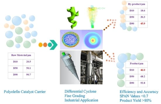
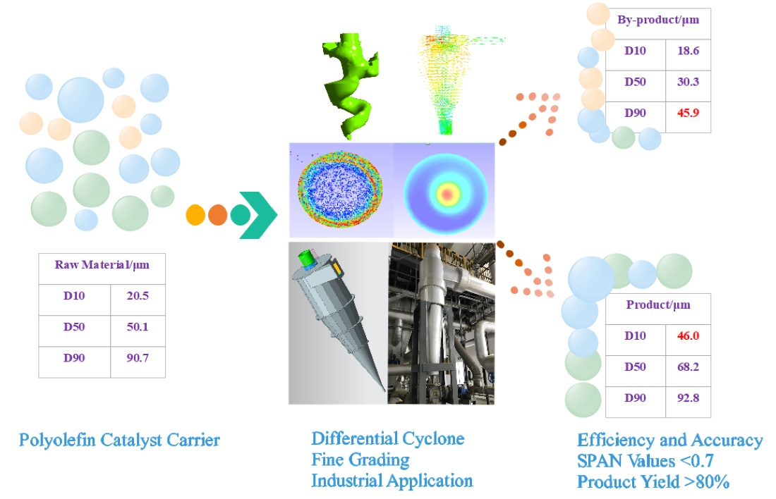
:In the process of preparing polyolefin catalyst carrier, the particle size is often unqualified because of the adhesion of smaller particles to each other and the crushing effect of mechanical vibration. To improve the output of target products, reduce loss, and improve yield, a high-precision and high-efficiency carrier particle classification process was developed according to the embedded principle. The hydraulic hydrocyclone equipment designed in this work could eliminate short-circuit flow and achieve good integration of the internal flow field, thereby enhancing the separation accuracy and high separation efficiency. The process was successfully applied to the industry with smooth operation. The large-ball polyolefin catalyst carrier prepared by grading showed a small distribution coefficient, high yield, and excellent polymerization performance, and the average particle size of the graded large ball catalyst support was 65–75 μm with the SPAN < 0.7, which could meet the needs of DQC700 series catalyst products.
1. Introduction
At present, polyolefin technology has become one of the most important research and development directions for synthetic resin technology. Depending on the media used for the polymerization reactions and the structure of the polymer reactors, the main polypropylene production processes were divided into three categories: Slurry process, ontogenetic process, and gas-phase method process. The slurry process, also known as the silting process or solvent process, was the most primitive process technology for polypropylene production and has dominated the worldwide list of polypropylene production processes for nearly 30 years. The high-efficiency, high-dimensional selective catalyst was employed in the slurry process to simplify the production process, so that the consumption of raw materials and energy was greatly reduced. The ontogenetic processes were mainly used in the Borstar [1,2,3] process of the Nordic chemical industry, the Hypol process [4,5] of Mitsui Chemical in Japan, the Spheripol process of Basell [6,7,8], etc. The gas-phase method process was employed in the Japanese Mitsui Petrochemical Company, the United States DOW Chemical Company [9,10,11], Ineos, and Lummus [12,13].
By the existing screening process methods of grading the carrier, it is not possible to achieve the precise classification of carrier particle size. Due to the agglomeration phenomenon and low yield in the screening process, most screening studies have reported that the SPAN value of products prepared by screening classification could only reach approximately 1.0, meaning that the higher particle size distribution coefficient would affect the catalyst performance. Therefore, it was necessary to use other grading processes to improve the concentration of the target carrier particles. At present, in the field of catalyst carrier preparation and classification, screening classification technology has been gradually replaced by hydrohydrocyclone classification technology. There is no agglomeration phenomenon in the process of hydrohydrocyclone classification technology, which has the advantages of high efficiency, high yield, low cost, high accuracy, and the ability to achieve precise differential classification, and the SPAN value of the prepared catalyst carrier products can reach levels below 1.0, which is better than levels reached by previous studies [14,15].
In this paper, the carrier with D50 of 50.1 μm and SPAN value < 1.2 was directly prepared with great success. The hydraulic hydrocyclone equipment designed in this work could eliminate short-circuit flow and achieve good integration of the internal flow field, thereby enhancing the separation accuracy and separation efficiency. Finally, D10 of the products was 46.0 μm, and D90 of the by-products was 45.9 μm after grading; therefore, from the particle size distribution it was found that the separation accuracy had reached a very high level, which has not been reported thus far.
In the process of hydraulic hydrocyclone separation, the solid particles were suspended with the slurry along the tangent direction into the hydrocyclone, the slurry body was forced to make a swing motion upon encountering the wall of the instrument, while the solid particles following the original linear motion of the inertia continued to move forward. The inertia force of coarse particles was large and could overcome the water resistance to approach the hydrocyclone wall, while the inertia force of fine particles was small and they rotated with the slurry before approaching the wall. Under the impetus of the subsequent feeding, the slurry continued to move downwards and swing, and the solid particles produced inertial centrifugal forces accordingly. The coarse particles then continued to thicken to the periphery, while the fine particles remained in the central area. This resulted in a layered arrangement of coarse particles from the wall to the center [14,15].
Of course, the inertial centrifugal force forced both solid particles and slurry liquid, —from the inside out, layer by layer—to move to the wall. The liquid pressure was balanced with the feed pressure. This is why the hydrocyclone had to have a certain feed pressure [16]. This centrifugal movement tendency of the slurry also made it impossible for it to discharge directly from the overflow tube after entering the hydrocyclone; it could only make a downward swing movement. However, though it is possible for it to discharge directly from the overflow tube, if the feed pressure is very small, the slurry cannot form sufficient swing speed, meaning that the coarse particles cannot be graded according to granularity [17].
As the slurry flowed from the column part of the hydrocyclone to the cone part, the flow section became smaller and smaller. Under the pressure of the outer slurry contraction, the inner slurry had to change direction and flow upward. Two sets of rotating streams were formed in the hydrocyclone; of course, their tangential flow remained consistent, only in axial changes. At the transition point of the flow, the speed was zero. The zero-speed points were connected. In space, an open cup-shaped surface can be formed, namely, an axial zero-speed envelope. The fine particles in the envelope face are brought into the overflow, and the coarse particles outside the envelope surface enter the underflow port, so that the spatial position of the envelope surface determines the size of the separation granularity [18,19].
The carrier was graded according to certain particle size because the requirements of the structure and size of the hydrohydrocyclone were high. Meanwhile, the parameters related to the operation process needed to be relatively stable, to ensure that the cutting particle size was matched with the design and that the carrier particle size was less than and larger than the cutting particle size of the part through the overflow port and the underflow port, which was divided into two parts, to achieve the purpose of grading [20,21]. The particle size of the carrier graded by the hydrocyclone fine classification process was finally D50 of 68.2 μm with the SPAN value < 0.7 and a yield of approximately 45%. The catalyst process unit was successfully used in industrial applications with smooth operation, realizing the combination of experimental research and industrial application.
2. Experimental
2.1. Carrier Particle Classification Process
The magnesium chloride and ethanol reacted at a certain temperature in the melting kettle to produce a magnesium chloride alcohol compound, which was dissolved in the form of molten droplets in the dispersion medium (white oil and silicone oil mixture) (Figure 1). With the mixture melting into the high-speed rotation of the super-power rotating bed and the alcohol liquid droplets put under the action of the overweight force engendered by rotating the bed screen shear, the molten droplets were forced to disperse into a more homogeneous size of small droplets. The hexane melting droplets were quickly cured into a spherical carrier, and the carrier particles were obtained by washing and drying.
2.2. Measurement
During the separation process, the carrier hexane suspension sample analysis was taken, the carrier suspension was blow-dried, and then the dry particle size distribution was analyzed using the Mastersizer 3000 ultra-high-speed intelligent particle size analyzer of Malvern Corporation of the United Kingdom.
3. Results and Discussion
3.1. Spherical Carrier Fine Grade Amplification
3.1.1. Process Flow
According to the production process and equipment of the plant, the test was divided into three stages.
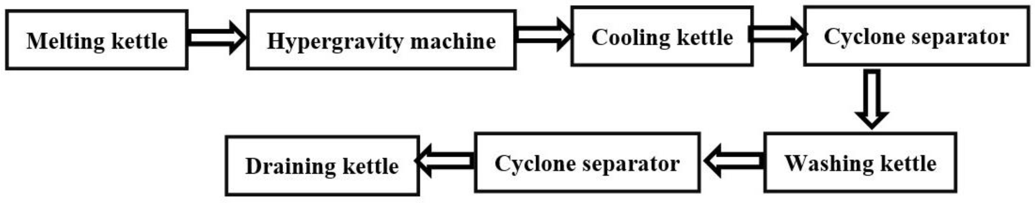
50-μm Hydrocyclone Separation after Washing the Kettle
At this stage, the basic equipment and preparation process of the existing carrier unit remained unchanged, the 95-μm hydrocyclone separator was embedded between the cooling kettle and the washing kettle, the 50-μm hydrocyclone separator was embedded between the washing kettle and the draining kettle, and a 95-μm hydrocyclone separator was used to remove large particles from the carrier after the carrier hexane suspension had been washed and put into the 50-μm hydrocyclone separator to achieve the fine grading. The small particle size carrier was produced at the overflow port and the large particle size target carrier was produced at the underflow port, both of which entered a draining kettle separately (Figure 2).
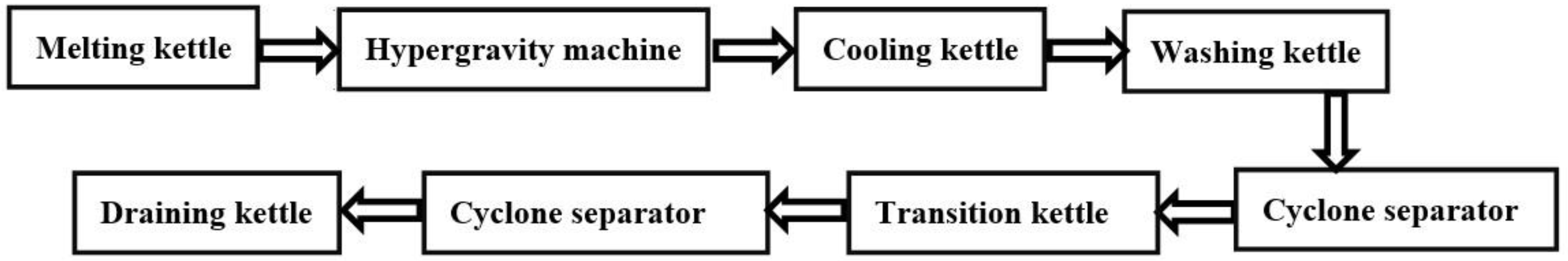
Increase the Hydrocyclone Separation Transition Kettle
The whole preparation process was unchanged except for the addition of a transition kettle between the washing kettle and the draining kettle (Figure 3). A 95-μm hydrocyclone separator was utilized after the washing kettle in order to remove the large particle carrier. The hexane suspension of the carrier prepared in the transition kettle was charged into a 50-μm hydrocyclone separator to achieve the fine grading. At the overflow port, the carriers with small particle size were charged into the transition kettle. At the underflow port, the carriers with large particle size were charged into the draining kettle.
Increased Solid Content Preparation Large Particle Size Carrier for the 50-μm Hydrocyclone Separation
Basically, Process 3 was the same as Process 2. In Process 3, the production of feed increased solid content into the carrier particle size of the separator, so that the 50-μm hydrocyclone separator can separate out the goal carrier (Figure 4).
Production Feeding Conditions
In the carrier production unit, a single kettle of magnesium chloride (78 kg), white oil, and silicone oil feed (900 L, reduced to 700 L in Phase 4) was used with a hypergravity machine speed of 2400 r/min. The carrier was removed by the 95-μm hydrocyclone separator and then charged into the 50-μm hydrocyclone separator (Table 1). A small particle size carrier was set at the overflow port and the underflow port was used for large particle size carriers.
3.1.2. Analysis and Discussion of Test Results
Directly Separating by the 50-μm Hydrocyclone after Washing
After washing the carrier, about hexane of 2000 L was added with a carrier concentration of approximately 17.6 wt% (after removing large particles, the amount of the carrier was approximately 325 kg). The residual hexane was washed in the kettle. The separation accuracy was controlled by adjusting the pressure difference between the inlet and overflow port (the proportion of particles larger than the separation target particle size at the bottom outlet). The test results were shown in Table 2 below.
From Table 2, the hydrocyclone separation presents the following features. Firstly, the particle size grading of particles can be initially achieved, resulting in a difference of D50 of more than 10 μm in size and the narrower distribution of the two-part carrier.
Secondly, with the increase of pressure difference, the separation accuracy also tends to increase. Due to the limitation of the unit, it was not possible to further increase the inlet pressure and increase the pressure difference.
At the same time, there were the following issues with the separation effect. Firstly, under the same conditions, the separation stability was insufficient, and some of the separation results were different. Secondly, due to the insufficient separation accuracy, the bottom port large particle size carrier reached 59 μm, which was below the design target (65 μm). The ZG-1-06 batch (0.28 MPa pressure) difference conditions were: the underflow port <50 μm particles at approximately 60% (volume ratio), the overflow port >50 μm particles at approximately 11% (volume ratio), and approximately 20% (volume ratio) of 50 μm particles > before separation. It can be seen that a large number of small particles were clamped in the underflow port, resulting in a low finishing particle size.
Since the volume of the washing kettle reached the upper limit of use, it was not possible to further increase the hexane content and reduce the carrier concentration. This was one of the causes of the poor stability and reduced separation efficiency.
The advantages of this test process were the small device and the direct embedment of the hydrocyclone separator on the existing unit pipe. However, the following problems with this process occurred during the test. Firstly, for each separation, the kettle carrier was required to drain the static drop pressure filter when the next separation was made at the end. The entire process took a long time and was unstable due to multiple interruptions. Secondly, the differences in import/exit pressure and the ratio of overflow/bottom outlet shunt were achieved by adjusting the opening of the valve.
The Rotary Flow Separation Intermediate Kettle
To solve the problem of excessive suspension concentration and partial operation, the device was partially modified, and two pumping dryers were added between the washing kettle and the draining kettle on the existing device. A large kettle R208 was used to configure carrier suspension, and a small kettle R209 was used to undertake overflow port materials. The 95-μm hydrocyclone separator was moved to the washing kettle, and the large particles were separated and charged into the intermediate kettle R208. The 50-μm hydrocyclone separator was set after R208, the overflow port entered R209, and the underflow port entered the draining kettle.
There were two notable benefits to be observed after the optimization of the process. Firstly, a lower concentration of carrier suspension could be configured before the 50-μm hydrocyclone separator. Secondly, the volume of the receiving kettle at the overflow port was improved, leading to a smaller separation number and enhanced separation efficiency.
As shown in Table 3, with the reduction of carrier (solid phase) concentration, the separation accuracy of the separator was gradually improved, and the particle size of the underflow mouth was greatly improved. When both reached more than 57 μm (of a maximum of 65.2 μm), the underflow mouth particle size was close to the target value. The adjustment expectations were met. The carrier particle size difference was larger between the underflow port and overflow port, and the clamping was more than the Process 1 reduction. For the ZG-2-03 batch, under 0.3 MPa pressure difference, the underflow port medium <50 μm particles accounted for approximately 40%.
To examine the stability of this condition, a series of repetitive experiments were carried out. The pressure difference selected the 0.25 MPa when the unit was running, and the concentration was selected to be 13 wt%.
As shown in Table 4, after the separation conditions were determined, the separation accuracy batch stability was good. The carrier particle size of the underflow port was stable at 61–63 μm, and there was still a certain gap from the target of 65 μm.
The analysis suggested that the target particle size was still not achieved, possibly due to the small particle size part of the carrier before separation. The particle size of >50 μm was approximately 20% (volume ratio), and the separation stay time was short due to the existence of too many particles with a small particle size. These particles could not all be separated from the overflow port, resulting in a large number of clamps into the underflow port and a low particle size of the underflow mouth.
There were two main advantages to Process 2. Firstly, a large volume intermediate kettle was able to configure a low concentration of carrier hexane slurry. Secondly, a large volume of overflow port was able to undertake an intermediate kettle, so that the separation process was intermittently reduced, which was conducive to the stability of the separation operation and the reduction of the operation time.
Increasing Solid Content to Prepare Large Particle Size Carrier by 50-μm Hydrocyclone Separator
Based on Process 2, the process was adjusted to improve the overall particle size of the separator entry carrier, to increase the large particle size carrier content, and to achieve the increase in underflow mouth particle size.
As shown in Table 5, the carrier particle size was increased and the underflow particle size was increased up to the target, almost reaching more than 65 μm. For the ZG-3-05 lot, the underflow port medium <50 μm particles accounted for approximately 15% (volume) and the overflow flow port medium >50 μm particles accounted for approximately 10% (volume). The separation efficiency of Process 2 was significantly improved. The linkage test of the two-stage hydrocyclone separator was carried out on the device, and the separation effect was better, but the control process was also more complex.
50-μm Hydrocyclone Separation Process vs. Screening Process
According to the comparison of Table 6, Table 7 and Table 8, there were four main advantages of the hydrocyclone separation process over the screening process. Firstly, the separation time of a single batch carrier was 20 h shorter than that of the screening process. Secondly, the separation accuracy was higher, the carrier distribution coefficient obtained by the hydrocyclone separation process was smaller, and the SPAN value was basically below 0.7. Thirdly, the carrier strength of hydrocyclone separation was better than that of screening separation. Fourthly, although the output efficiency of large particle size carriers in the hydrocyclone separation process was slightly low, it could fully meet the normal production needs of the catalyst.
Spin-Off Carrier Preparation Catalyst
As seen from Table 9, the performance of the catalyst prepared using the carrier separated by the 50-μm hydrocyclone separator was not significantly different from that of the imported carriers (BASELL company, Basel, Switzerland).
Hydrocyclone Separation Process Feasibility of Industrial Applications
Combined with the above test results, the designed hydrocyclone separation process showed high separation efficiency and separation accuracy. Under the conditions of the existing device, the inlet pressure was not required to be further improved, and the separation process remained stable for a long time, avoiding the reduction of underflow outlet flow caused by separation interruption and other reasons. Meanwhile, due to the structural conditions and technology characteristics of the hydrocyclone separation equipment, the internal flow field was well integrated, the bad phenomena such as short-circuit flow were well eliminated, and the problems of rough overflow port, fine underflow port, and low yield of underflow port were solved. Therefore, for the current catalyst carrier production unit, the process of fine classification of large ball carriers by hydrocyclone separator was successfully applied in the industry.
The hydrocyclone separator facilitated the fine classification of spherical catalyst support by adjusting the material concentration, controlling the pressure difference, and increasing the particle size of the inlet support. The D10 of the support product obtained was greater than 40 μm, D50 basically reached 65 μm, and the SPAN value was below 0.7.
The carrier obtained by hydrocyclone fine classification was directly used in subsequent catalyst production, with a short separation process and a high efficiency. To further expand the industrial application of the hydrocyclone separation process in carrier particle classification and improve the separation stability and yield of the large ball carrier at the underflow port, it was also necessary to comprehensively upgrade the equipment, metering, and transmission pressure, and optimize the hydrocyclone separator.
3.2. Large Particle Size Carrier System (Technical Optimization of Large Particle Size System Preparation)
3.2.1. Experiment Scenario
Introduction of the Key Equipment for the Formation of Large Spherical Catalyst Carrier—Hypergravity Machine
The reaction between magnesium chloride and ethanol in the alcohol synthesis kettle formed magnesium chloride alcoholate, which was dissolved in the dispersion medium (a mixture of white oil and silicone oil) in the form of molten droplets in a two-phase solution. The size of the molten droplets varied greatly under the action of pre-dispersion by stirring. The molten mixture entered the high-speed and high-gravity rotating bed through the feed pipe (Figure 5). The alcoholate droplets were thrown out through the rotating bed wire mesh under the action of centrifugal force and were forced to shear during contact with the wire mesh. They were fully dispersed into droplets of relatively uniform size. The droplets that melted in the low-temperature hexane that entered the cooling kettle were quickly solidified into a spherical carrier, and the carrier particles were finally obtained by washing and drying.
Pilot Technical Scheme
According to the results of the preliminary results and the experience of small-test and long-term industrial production, the influence of the following factors on particle size was investigated, and a large particle size carrier was prepared according to the results.
The effects of the changes in the rotating packed bed speed and the screen on the particle size were investigated. The effects of the speed change of the alcohol kettle on the pre-dispersion effect and particle size were studied. The proportion of white oil and silicone oil volume and the proportion of magnesium chloride in the mixture (solid content) were investigated on the size of carrier particle size. According to the above results, the large particle size carrier was prepared, and the DQC700 catalyst was prepared with it.
3.2.2. Test Results Discussion and Analysis
The carrier was examined when the speed of the hypergravity machine was changed from 2400 to 500 r/min.
The results in Table 10 show that decreasing speed leads to increased carrier particle size. When the increasing extent was small, the change was not obvious, and the carrier particle size distribution was wider at low speed. For the length of the hypergravity machine screen at 8–33 m, the effect of the number of screen layers on carrier particle size was studied when the number of layers varied from 7–27 layers.
The results in Table 11 show that there was no significant change in carrier particle size and particle size distribution, but that the number of winding layers decreased with the length of the screen.
It was found that the diameter of the droplets decreased with the increasing thickness of the screen. The thicker screen resulted in a stronger shearing capacity. Initially, the thickness increased when the size of the droplets rapidly decreased. But when the thickness of the screen increased to a certain extent, the particle size no longer continued to decrease.
The range of net thickness change selected in the experiment had little effect on carrier particle size, possibly because the thickness was not reduced to the critical value for the particle size change. However, the support strength was insufficient when the test was reduced to the current thickness, and only one batch of test nets was deformed seriously.
When the speed of the molten kettle was changed from 160 r/min to 50 r/min, the change of carrier particle size was studied.
As shown in Table 12, the stirring speed of the melting kettle was reduced to 70 r/min, the carrier particle size and particle size distribution did not vary significantly. When it was further reduced to 50 r/min, the carrier particle size was increased significantly. At the same time, when D50 and D90 were increased significantly, the distribution became very wide. The sudden variation in particle size perhaps occurred because the alcoholate droplets could not be uniformly dispersed in the medium when the stirring was reduced to a certain speed, resulting in the uneven size of the molten droplets and widened distribution.
In addition to the pre-dispersion of the alcohol compound droplets, the stirring of the melting kettle also played a role in dispersing and mixing the previous reaction between magnesium chloride and ethanol. The too-low stirring speed could not ensure the dispersion effect of magnesium chloride, resulting in the incomplete reaction with ethanol. At the stirring speed of 50 r/min, some magnesium chloride still failed to react and melt at the end of the constant temperature.
The impact of the granularity distribution of the carrier was studied when the volume ratio of the feed silicone oil to white oil varied from 8/1 to 2/7.
Table 13 showed that the proportion of white oil increased. When the proportion of white oil was less than 1:1, the carrier particle size increased, but the increase was limited and the separation width increased slightly. When the white oil ratio was greater than 1:1, the particle size increased rapidly and the distribution was significantly wider. In daily production, the effective regulation of particle size could be achieved by adjusting the ratio of white silicone oil within a certain range.
The carrier particle size was investigated with the magnesium chloride feed of 35–140 kg.
As shown in Table 14, as the amount of feed was increased, the carrier particle size gradually increased and the particle size increased by a large margin, but the particle size distribution did not widen.
The analysis should be due to an increase in the amount of magnesium chloride cast (the solid content of the feed), i.e., an increase in the concentration of dispersed phases (alcohol compound droplets) in the dispersed medium (white oil and silicone oil). When the number of magnesium chloride alcohol compounds per unit volume was increased, the chance of droplet collision binding increased and it became easier to produce large droplets. Correspondingly, after the dispersion of the overweight force, before the incomplete solidity, in the super-heavy force machine kettle bottom and outlet pipe, as well as in the cooling hexane, droplet adhesion probability was also larger. Therefore, after the solid content was increased, the carrier particle form was deteriorated, resulting in more particle adhesion and alien particles. The above analysis was also verified by the comparison of carrier morphology of 65 kg (left) and 140 kg (right) magnesium chloride in Figure 6.
The large particle size carriers required for DQC700 catalysts were produced by increasing the volume ratio (1:2) of white oil silica oil to magnesium chloride on the carrier unit.
As shown in Table 15, by adjusting the production conditions, the carrier with D50 > 70 μm and SPAN < 1.05 can be prepared directly. The technical objectives of the project were to obtain the carrier with the particle size of D50 70–80 μm and the SPAN ≤ 1.2. However, when preparing the catalyst, the SPAN value was still high and the separation and grading of the carrier were required.
Table 16 showed that the prepared catalyst support was efficiently and accurately classified by the hydrocyclone fine separation process. The large ball catalyst support with the particle size D50 was above 70 μm and the SPAN < 0.7 was obtained, and the yield was improved to approximately 45%. The DQC700 catalyst was prepared using the large-ball carrier system with the hydrocyclone fine separation process.
Table 17 showed that the D50 of the prepared DQC700 catalyst particles was above 70 μm, and all indexes were normal. At the same time, in the polymerization performance index of the large ball catalyst synthesized by the large particles prepared by fine grading, the particle size distribution of the polymer met the requirement that the polymer content with the size of less than 40 μm was no more than 1%. The particle size reached the level of foreign target catalyst, and the distribution was narrower.
4. Conclusions
This study has shown that, with the advantages of high efficiency, high yield, low cost, and high accuracy, hydrocyclone classification technology can achieve precise differential classification of polyolefin catalyst carriers, the SPAN value of the prepared catalyst carrier products being the best compared with previous studies. At the same time, the effect of parameters on the carrier particle size was thoroughly investigated, and the process of preparing the carrier with a large particle size was optimized. The carrier with D50 of 50.1 μm and SPAN value < 1.2 was directly prepared with great success. The hydraulic hydrocyclone equipment designed in this work could eliminate short-circuit flow and achieve good integration of the internal flow field, thereby enhancing the separation accuracy and separation efficiency. Finally, D10 of the products was 46.0 μm, and D90 of the by-products was 45.9 μm after grading. The particle size of the carrier graded by the hydrocyclone fine classification process was finally D50 of 68.2 μm, with a SPAN value < 0.7 and a yield of approximately 45%. The catalyst process unit was successfully used in industrial applications with smooth operation, and the catalyst obtained reached the level of imported products (BASELL company).
Author Contributions
Conceptualization, X.L. and Y.D.; methodology, X.L.; software, X.L. and Y.D.; validation, X.L., S.D. and L.X.; formal analysis, X.L.; investigation, X.L.; resources, X.L.; data curation, X.L.; writing original draft preparation, X.L.; writing review and editing, X.L., S.D. and L.X.; visualization, X.L.; supervision, X.L., S.D. and L.X.; project administration, X.L., S.D. and L.X.; funding acquisition, L.X. All authors have read and agreed to the published version of the manuscript.
Funding
This work was supported by the National Natural Science Foundation of China [grant numbers 21978153] and the National Key Research and Development Program [grant number 2019YFC1905803].
Data Availability Statement
The data presented in this study are available on request from the corresponding author.
Conflicts of Interest
The authors declare no conflict of interest.
References
- Larsson, P.-O.; Åkesson, J.; Carlsson, N.; Andersson, N. Model-based optimization of economical grade changes for the Borealis Borstar® polyethylene plant. Comput. Chem. Eng. 2012, 46, 153–166. [Google Scholar] [CrossRef]
- Soares, J.B.P. Mathematical modelling of the microstructure of polyolefins made by coordination polymerization: A review. Chem. Eng. Sci. 2001, 56, 4131–4153. [Google Scholar] [CrossRef]
- Covezzi, M.; Mei, G. The multizone circulating reactor technology. Chem. Eng. Sci. 2001, 56, 4059–4067. [Google Scholar] [CrossRef]
- Luo, Z.-H.; Su, P.-L.; Shi, D.-P.; Zheng, Z.-W. Steady-state and dynamic modeling of commercial bulk polypropylene process of Hypol technology. Chem. Eng. J. 2009, 149, 370–382. [Google Scholar] [CrossRef]
- Pluta, T.; Sadlej, A.J. HyPol basis sets for high-level-correlated calculations of electric dipole hyperpolarizabilities. Chem. Phys. Lett. 1998, 297, 391–401. [Google Scholar] [CrossRef]
- Urdampilleta, I.; González, A.; Iruin, J.J.; de la Cal, J.C.; Asua, J.M. Origins of product heterogeneity in the spheripol high impact polypropylene process. Ind. Eng. Chem. Res. 2006, 45, 4178–4187. [Google Scholar] [CrossRef]
- Zheng, Z.-W.; Shi, D.-P.; Su, P.-L.; Luo, Z.-H.; Li, X.-J. Steady-state and dynamic modeling of the basell multireactor olefin polymerization process. Ind. Eng. Chem. Res. 2011, 50, 322–331. [Google Scholar] [CrossRef]
- Luo, Z.-H.; Su, P.-L.; Wu, W. Industrial loop reactor for catalytic propylene polymerization: Dynamic modeling of emergency accidents. Ind. Eng. Chem. Res. 2010, 49, 11232–11243. [Google Scholar] [CrossRef]
- UNIPOL PP Process Technology Used in Coal-to-Olefins Plant in China. China Chem. Rep. 2010, 21, 11.
- Lau, C.K.; Heng, Y.S.; Hussain, M.A.; Nor, M.I.M. Fault diagnosis of the polypropylene production process (UNIPOL PP) using ANFIS. ISA Trans. 2010, 49, 559–566. [Google Scholar] [CrossRef] [PubMed]
- Zacca, J.J.; Debling, J.A.; Ray, W.H. Reactor residence time distribution effects on the multistage polymerization of olefins—I. Basic principles and illustrative examples, polypropylene. Chem. Eng. Sci. 1996, 51, 4859–4886. [Google Scholar] [CrossRef]
- Alperowicz, N. Novolen technology likely for mangalore PP Complex. Chem. Week 2009, 171, 27. [Google Scholar]
- Amec, I.Y. Foster Wheeler, Novolen Win Big Awards in China. Chem. Week 2006, 168, 20. [Google Scholar]
- Cullivan, J.C.; Williams, R.A.; Cross, R. Understanding the hydrocyclone separator through computational fluid dynamics. Chem. Eng. Res. Des. 2003, 81, 455–466. [Google Scholar] [CrossRef]
- Wu, S.-E.; Hwang, K.-J.; Cheng, T.-W.; Hung, T.-C.; Tung, K.-L. Effectiveness of a hydrocyclone in separating particles suspended in power law fluids. Powder Technol. 2017, 320, 546–554. [Google Scholar] [CrossRef]
- Dubey, R.; Singh, G.; Majumder, A. Roping: Is it an optimum dewatering performance condition in a hydrocyclone? Powder Technol. 2017, 321, 218–231. [Google Scholar] [CrossRef]
- Patra, G.; Velpuri, B.; Chakraborty, S.; Meikap, B.C. Performance evaluation of a hydrocyclone with a spiral rib for separation of particles. Adv. Powder Technol. 2017, 28, 3222–3232. [Google Scholar] [CrossRef]
- Liu, Y.; Cheng, Q.; Zhang, B.; Tian, F. Three-phase hydrocyclone separator—A review. Chem. Eng. Res. Des. 2015, 100, 554–560. [Google Scholar] [CrossRef]
- Colli, A.N.; Fornés, J.P.; Pérez, O.G.; Bisang, J.M. Evaluation of a modified hydrocyclone as electrochemical reactor for processing of two-phase (gas-liquid) systems. Electrochim. Acta 2019, 309, 219–227. [Google Scholar] [CrossRef]
- Xu, X.; Yang, Q.; Wang, C.-Y.; Ge, X.-L.; Wang, H.-L. Dissolved gas separation using the pressure drop and centrifugal characteristics of an inner cone hydrocyclone. Sep. Purif. Technol. 2016, 161, 121–128. [Google Scholar] [CrossRef]
- Wang, C.-C.; Wu, R.-M. Experimental and simulation of a novel hydrocyclone-tubular membrane as overflow pipe. Sep. Purif. Technol. 2018, 198, 60–67. [Google Scholar] [CrossRef]
Figure 1.
Overweight process spherical polypropylene catalyst system preparation process diagram.

Figure 2.
The 50-μm hydrocyclone separation test in Process 1.

Figure 3.
The 50-μm hydrocyclone separation test in Process 2.

Figure 4.
The 50-μm hydrocyclone separation test in Process 3.

Figure 5.
Structure of the hypergravity machine and the interior of the rotating packed bed.

Figure 6.
65 kg (left) and 140 kg (right) magnesium chloride feed carrier form comparison.


Table 1.
Geometric Structure Parameters of the 50-μm Hydrocyclone.
| Parameter | Value (mm) |
|---|---|
| Body diameter | 478 |
| Inlet diameter | 188 |
| Vortex-finder diameter | 230 |
| Spigot diameter | 202 |
| Vortex-finder length | 257 |
| Cylindrical-part length | 478 |
| Included angle | 20° |
Table 2.
Stream separation test data for Process 1.
| Lot Number | Pressure Differential MPa 1 | Overflow Port Carrier D50 μm | Underflow Port Carrier D50 μm |
|---|---|---|---|
| ZG-1-01 | 0.16 | 41.7 | 50.9 |
| 0.16 | 41.5 | 53.7 | |
| ZG-1-02 | 0.18 | 40.0 | 46.7 |
| 0.18 | 32.1 | 52.5 | |
| ZG-1-03 | 0.20 | 43.3 | 49.8 |
| 0.20 | 45.1 | 47.2 | |
| ZG-1-04 | 0.23 | 42.8 | 50.3 |
| 0.23 | 31.3 | 46.6 | |
| ZG-1-05 | 0.24 | 39.8 | 52.2 |
| ZG-1-06 | 0.28 | 37.7 | 53.1 |
| ZG-1-07 | 0.30 | 40.7 | 56.6 |
| 0.30 | 36.9 | 59.7 | |
| 0.30 | 40.0 | 50.0 |
1 The pressure difference was the difference between the import and overflow port, which was achieved by adjusting the opening of the import and export valve.
Table 3.
Hydrocyclone separation concentration adjustment test data for Process 2.
| Test Batch | Carrier Concentration (wt%) | Pressure Difference 1 (MPa) | Overflow Port Carrier D50 μm | Underflow Port Carrier D50 μm |
|---|---|---|---|---|
| ZG-2-01 | 16.4 | 0.30 | 38.2 | 57.4 |
| 0.27 | 37.5 | 50.1 | ||
| 0.25 | 38.6 | 43.2 | ||
| ZG-2-02 | 14.9 | 0.30 | 39.4 | 60.9 |
| 0.27 | 38.7 | 56.9 | ||
| 0.25 | 32.2 | 55.6 | ||
| ZG-2-03 | 14.1 | 0.30 | 42.8 | 65.2 |
| 0.27 | 33.6 | 59.9 | ||
| 0.25 | 33.7 | 59.8 | ||
| ZG-2-04 | 13.0 | 0.30 | 39.5 | 61.9 |
| 0.27 | 43.4 | 61.8 | ||
| 0.25 | 40.9 | 63.5 |
1 The pressure difference was the difference between the import and overflow port, which was based on the opening of the import and export valve.
Table 4.
Repeated stability test data of hydrocyclone separation in process flow 2.
| Test Batch | Sample | Overflow Port Carrier D50 μm | Underflow Port Carrier D50 μm |
|---|---|---|---|
| ZG-2-05 | Sample 1 | 40.8 | 63.0 |
| Sample 2 | 41.0 | 63.2 | |
| ZG-2-06 | Sample 1 | 42.2 | 62.9 |
| Sample 2 | 40.6 | 61.4 | |
| ZG-2-07 | Sample 1 | 40.6 | 62.1 |
| Sample 2 | 41.9 | 61.7 |
Table 5.
Large particle size carrier 50 μm spin flow separation test data.
| Lot Number 1 | Pre-Separation Carrier D50 μm | Overflow Port Carrier D50 μm | Underflow Port Carrier D50 μm |
|---|---|---|---|
| ZG-3-01 | 36.8 | 33.7 | 51.5 |
| ZG-3-02 | 45.5 | 38.4 | 63.0 |
| ZG-3-03 | 46.7 | 36.8 | 65.1 |
| ZG-3-04 | 46.9 | 37.6 | 66.5 |
| ZG-3-05 | 47.1 | 35.5 | 65.0 |
1 Concentration 13 wt%, pressure difference 0.24 MPa.
Table 6.
Hydrocyclone separation carrier span value and yield 1.
| Lot Number | D10 μm | D50 μm | D90 μm | SPAN | Weight kg | Remark |
|---|---|---|---|---|---|---|
| CS-01 | 18.0 | 33.8 | 46.7 | 0.66 | 178.8 | Overflow port |
| 45.0 | 65.1 | 85.9 | 0.65 | 130.0 | Underflow port | |
| CS-02 | 19.7 | 31.6 | 42.2 | 0.70 | 171.8 | Overflow port |
| 48.4 | 66.5 | 90.8 | 0.69 | 129.6 | Underflow port | |
| CS-03 | 13.6 | 25.5 | 49.2 | 0.72 | 187.9 | Overflow port |
| 46.5 | 65.0 | 80.9 | 0.53 | 122.1 | Underflow port |
1 Batch separation takes approximately 3 h.
Table 7.
Screening carrier span values and yields 1.
| Lot Number | D10 μm | D50 μm | D90 μm | SPAN | Weight kg | Remark |
|---|---|---|---|---|---|---|
| SG-01 | 41.5 | 50.9 | 84.2 | 0.73 | 138.9 | >250 |
| 23.8 | 36.8 | 57.4 | 0.91 | 186.4 | <250 | |
| SG-02 | 46.8 | 61.9 | 80.0 | 0.54 | 153.0 | >250 |
| 24.6 | 39.7 | 56.9 | 0.81 | 170.3 | <250 | |
| SG-03 | 45.4 | 63.7 | 87.3 | 0.66 | 159.7 | >250 |
| 29.8 | 41.0 | 56.0 | 0.64 | 173.1 | <250 |
1 Batch separation time was approximately 24 h.
Table 8.
Comparison of hydrocyclone separation and screening separation on carrier strength 1.
| Sample Lot Number | D50 μm | Strength Factor L | Remark |
|---|---|---|---|
| CS-01 | 65.1 | 0.146 | Hydrocyclone separation |
| CS-03 | 65.0 | 0.152 | Hydrocyclone separation |
| SG-04 | 57.0 | 0.225 | Screening separation |
| SG-05 | 56.1 | 0.265 | Screening separation |
1 Carrier strength formula: L: (D50 (0 min)-D50 (20 min))/D50 (10 min).
Table 9.
Performance comparison of catalysts prepared using a 50-μm hydrocyclone separator carrier and imported catalyst (BASELL company).
Table 9.
Performance comparison of catalysts prepared using a 50-μm hydrocyclone separator carrier and imported catalyst (BASELL company).
| Lot Number | Ti (%) | DIBP (%) | DEP (%) | Volatile | D10 | D50 | D90 | Span | Activity | BD |
|---|---|---|---|---|---|---|---|---|---|---|
| CP-01 | 2.28 | 8.19 | 1.16 | 13.06 | 40.1 | 67.5 | 93.5 | 0.68 | 6.77 | 0.475 |
| Imported-1 | 2.32 | 8.13 | 1.39 | 13.51 | 39.9 | 64.1 | 95.1 | 0.72 | 6.19 | 0.475 |
| Imported-2 | 2.28 | 7.98 | 1.35 | 13.48 | 41.3 | 66.9 | 96.9 | 0.70 | 6.04 | 0.471 |
Table 10.
Effect of the speed of the overweight force on the carrier particle size.
| Numbering | Hypergravity Machine Speed (rpm) | Carrier Particle Size (μm) | SPAN | Alcohol-Magnesium Ratio 1 | ||
|---|---|---|---|---|---|---|
| D10 | D50 | D90 | ||||
| CP-1-01 | 2400 | 26.3 | 45.0 | 76.9 | 1.12 | 2.61 |
| CP-1-02 | 2000 | 30.3 | 50.3 | 84.2 | 1.07 | 2.62 |
| CP-1-03 | 1600 | 29.5 | 52.5 | 92.8 | 1.21 | 2.59 |
| CP-1-04 | 800 | 23.8 | 50.9 | 94.1 | 1.38 | 2.57 |
| CP-1-05 | 500 | 26.3 | 50.2 | 89.4 | 1.26 | 2.62 |
1 The alcohol-magnesium ratio (n (Ethanol/MgCl2)) was the molar ratio of ethanol to MgCl2 in the carrier, the same as below.
Table 11.
Effect of the length and thickness of the excess force rotating packed bed screen on the carrier particle size.
Table 11.
Effect of the length and thickness of the excess force rotating packed bed screen on the carrier particle size.
| Numbering | Screen Length (m) | Number of Screen Layers | Carrier Particle Size (μm) | SPAN | Alcohol-Magnesium Ratio | ||
|---|---|---|---|---|---|---|---|
| D10 | D50 | D90 | |||||
| CP-2-01 | 33 | 27 | 26.5 | 44.7 | 73.3 | 1.04 | 2.69 |
| CP-2-02 | 28 | 23 | 29.1 | 44.6 | 69.4 | 0.90 | 2.65 |
| CP-2-03 | 24 | 19 | 27.8 | 45.0 | 70.3 | 0.94 | 2.56 |
| CP-2-04 | 16 | 13 | 27.2 | 45.6 | 77.1 | 1.09 | 2.65 |
| CP-2-05 | 8 | 7 | 23.8 | 46.5 | 80.3 | 1.22 | 2.66 |
Table 12.
Effect of the melting kettle stirring speed on carrier particle size.
| Numbering | Melt the Kettle Speed (r/min) | Carrier Particle Size (μm) | SPAN | Alcohol-Magnesium Ratio | ||
|---|---|---|---|---|---|---|
| D10 | D50 | D90 | ||||
| CP-3-01 | 160 | 27.5 | 47.2 | 82.1 | 1.16 | 2.56 |
| CP-3-02 | 130 | 27.0 | 47.1 | 76.8 | 1.06 | 2.57 |
| CP-3-03 | 70 | 27.7 | 47.4 | 80.1 | 1.11 | 2.57 |
| CP-3-04 | 50 | 23.9 | 60.6 | 129.2 | 1.74 | 2.50 |
Table 13.
Effect of the white oil/silicon oil volume ratio on carrier particle size.
| Numbering | White Oil Volume (L) | Silicone Oil Volume (L) | Carrier Particle Size (μm). | SPAN | Alcohol-Magnesium Ratio | ||
|---|---|---|---|---|---|---|---|
| D10 | D50 | D90 | |||||
| CP-4-01 | 100 | 800 | 27.9 | 42.4 | 65.3 | 0.88 | 2.66 |
| CP-4-02 | 150 | 750 | 25.6 | 44.8 | 69.1 | 0.97 | 2.60 |
| CP-4-03 | 180 | 720 | 30.4 | 47.0 | 73.1 | 0.91 | 2.60 |
| CP-4-04 | 200 | 700 | 28.1 | 45.9 | 75.0 | 1.02 | 2.55 |
| CP-4-05 | 230 | 670 | 28.9 | 46.8 | 75.8 | 1.00 | 2.55 |
| CP-4-06 | 300 | 600 | 27.3 | 47.0 | 80.8 | 1.13 | 2.55 |
| CP-4-07 | 450 | 450 | 22.9 | 70.5 | 129.4 | 1.51 | 2.53 |
| CP-4-08 | 600 | 300 | 28.3 | 68.5 | 133.4 | 1.53 | 2.53 |
| CP-4-09 | 700 | 200 | 24.3 | 74.8 | 182.6 | 2.11 | 2.52 |
Table 14.
Effect of magnesium chloride feeding on carrier particle size.
| Numbering | Magnesium Chloride Input (kg) | Carrier Particle Size (μm) | SPAN | Alcohol-Magnesium Ratio | ||
|---|---|---|---|---|---|---|
| D10 | D50 | D90 | ||||
| CP-5-01 | 36 | 25.8 | 40.2 | 64.4 | 0.96 | 2.66 |
| CP-5-02 | 65 | 24.3 | 40.2 | 62.1 | 0.94 | 2.63 |
| CP-5-03 | 78 | 31.7 | 47.2 | 71.1 | 0.84 | 2.61 |
| CP-5-04 | 86 | 31.5 | 49.8 | 80.3 | 0.98 | 2.56 |
| CP-5-05 | 98 | 35.0 | 52.3 | 78.7 | 0.84 | 2.52 |
| CP-5-06 | 106 | 35.9 | 56.5 | 88.4 | 0.93 | 2.50 |
| CP-5-07 | 120 | 37.5 | 63.0 | 108.8 | 1.13 | 2.50 |
| CP-5-08 | 140 | 44.6 | 72.0 | 117.8 | 1.02 | 2.54 |
Table 15.
Large particle size carriers required to prepare DQC700 catalysts.
| Numbering | Magnesium Chloride Input (kg) | Carrier Particle Size (μm) | SPAN | Alcohol-Magnesium Ratio | ||
|---|---|---|---|---|---|---|
| D10 | D50 | D90 | ||||
| CP-01 | 120 | 37.5 | 63.0 | 108.8 | 1.13 | 2.50 |
| CP-02 | 120 | 37.7 | 63.6 | 106.2 | 1.08 | 2.53 |
| CP-03 | 120 | 33.7 | 61.1 | 112.4 | 1.09 | 2.60 |
| CP-04 | 140 | 44.6 | 72.0 | 117.8 | 1.02 | 2.54 |
| CP-05 | 140 | 45.5 | 74.1 | 121.1 | 1.02 | 2.55 |
Table 16.
The hydrocyclone accurate classification results of catalyst carrier.
| Lot Number | Conditions | D10μm | D50μm | D90μm | SPAN | Weight (kg) | Yield |
|---|---|---|---|---|---|---|---|
| CP-06 | Before grading | 44.6 | 52.0 | 117.8 | 1.02 | 308.4 | |
| Overflow port | 19.4 | 32.4 | 58.8 | 0.74 | 166.5 | 54% | |
| Underflow port | 50.1 | 74.1 | 97.8 | 0.66 | 140.6 | 46% | |
| CP-07 | Before grading | 45.5 | 54.1 | 121.1 | 1.00 | 336.0 | |
| Overflow port | 25.1 | 41.7 | 61.9 | 0.83 | 188.7 | 56% | |
| Underflow port | 59.8 | 78.3 | 110.8 | 0.68 | 144.5 | 43% |
Table 17.
Performance of prepared DQC700 catalyst.
| Lot Number | Ti % | DIBP % | DEP % | Volatile % | D10 μm | D50 Μm | D90 μm | SPAN | Activity | BD | MI g/min 1 | II % |
|---|---|---|---|---|---|---|---|---|---|---|---|---|
| CP-01 | 3.12 | 11.04 | 0.27 | 12.13 | 55.3 | 73.2 | 95.1 | 0.64 | 6.40 | 0.468 | 27.9 | 97.6 |
| Goal | 50.0 | 71.0 | 96.0 | 0.68 |
1 MI was polymer detection at 0.9 MPa hydrogenated for 1 h, II% was polymer detection at 0.2 MPa hydrogenated for 2 h.
Publisher’s Note: MDPI stays neutral with regard to jurisdictional claims in published maps and institutional affiliations. |
© 2022 by the authors. Licensee MDPI, Basel, Switzerland. This article is an open access article distributed under the terms and conditions of the Creative Commons Attribution (CC BY) license (https://creativecommons.org/licenses/by/4.0/).
Share and Cite
MDPI and ACS Style
Lv, X.; Du, Y.; Du, S.; Xiang, L. Graded Preparation and Industrial Applications of Large-Ball Polyolefin Catalyst Carriers. Catalysts 2022, 12, 117. https://0-doi-org.brum.beds.ac.uk/10.3390/catal12020117
AMA Style
Lv X, Du Y, Du S, Xiang L. Graded Preparation and Industrial Applications of Large-Ball Polyolefin Catalyst Carriers. Catalysts. 2022; 12(2):117. https://0-doi-org.brum.beds.ac.uk/10.3390/catal12020117
Chicago/Turabian StyleLv, Xinfeng, Yuhao Du, Shanjun Du, and Lan Xiang. 2022. "Graded Preparation and Industrial Applications of Large-Ball Polyolefin Catalyst Carriers" Catalysts 12, no. 2: 117. https://0-doi-org.brum.beds.ac.uk/10.3390/catal12020117
Note that from the first issue of 2016, this journal uses article numbers instead of page numbers. See further details here.