Unconventional Materials Processing Using Spark Plasma Sintering


Mechanical and Materials Engineering, Florida International University, Miami, FL 33174, USA
*
Author to whom correspondence should be addressed.
Ceramics 2021, 4(1), 20-39; https://0-doi-org.brum.beds.ac.uk/10.3390/ceramics4010003
Submission received: 14 December 2020
/
Revised: 31 December 2020
/
Accepted: 4 January 2021
/
Published: 8 January 2021
(This article belongs to the Special Issue Spark Plasma Sintering Technology)
Abstract
:Spark plasma sintering (SPS) has gained recognition in the last 20 years for its rapid densification of hard-to-sinter conventional and advanced materials, including metals, ceramics, polymers, and composites. Herein, we describe the unconventional usages of the SPS technique developed in the field. The potential of various new modifications in the SPS technique, from pressureless to the integration of a novel gas quenching system to extrusion, has led to SPS’ evolution into a completely new manufacturing tool. The SPS technique’s modifications have broadened its usability from merely a densification tool to the fabrication of complex-shaped components, advanced functional materials, functionally gradient materials, interconnected materials, and porous filter materials for real-life applications. The broader application achieved by modification of the SPS technique can provide an alternative to conventional powder metallurgy methods as a scalable manufacturing process. The future challenges and opportunities in this emerging research field have also been identified and presented.
1. Introduction
Spark plasma sintering (SPS) is an ultra-fast technique utilizing the electric field and pressure to consolidate and densify conventional and advanced materials. Although SPS technology’s fundamental principles were known over 50 years ago, the technology has gained attention only within the last 20 years. SPS has also been named as pulsed-electric current sintering, the field-assisted sintering technique, plasma-activated sintering, and current-activated pressure-assisted densification [1,2,3,4,5,6].
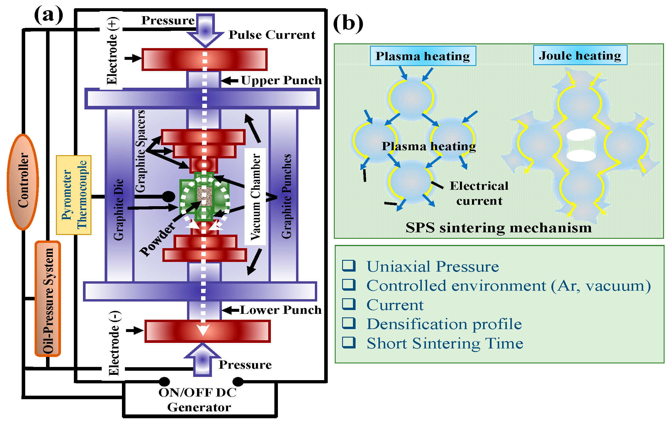
A variety of novel refractory materials, nanocrystalline materials, and advanced functional materials, including conventional metals, alloys, ceramics, polymers, and their composites, have been fabricated using SPS [7,8]. SPS employs a spark discharge in the voids between the loosely packed powder particles and consolidates them to near its full densification. The spark between the particles activates their surface, removes volatile impurities, surface oxide contaminations, and effectively self-heats the material. This localized effect enables the lower sintering temperature and shorter time and often leads to a dense fine-grained structure with higher strength [9]. Various other mechanisms such as plasma or micro-discharge of the particles’ surface, Joule heating, electromigration, local melting, and evaporation have also been reported for the conventional SPS technique. However, there is still a debate on whether plasma is being generated between the particles or not, with no specific conclusion drawn. The escalating implication of SPS technology as a tool for consolidating materials of desired interest is provided by the large number of academic papers published so far (>10,000; from Web of Science Core Collection). Figure 1a shows a simplified schematic of the SPS set up with all the components. SPS consists of a mechanical loading system, current controller, controlled atmosphere apparatus, and cooling system. The basic mechanisms involved during the SPS process, i.e., Joule’s heating and plasma heating, are schematically shown in Figure 1b. Many companies—Sinter Land Inc., Fuji Electronic Industrial Co. Ltd., Thermal Technology LLC Inc., FCT Systeme GmBH—deal with SPS machines’ production, nearly half of which being used for industrial applications [10].
In comparison with other sintering techniques, i.e., pressureless sintering (PS), hot pressing (HP), hot isostatic pressing (HIP), and microwave sintering (MS), characterized by relatively higher temperature and longer sintering durations, the SPS process is a rapid technique. This has been attributed to the generation of heat by electrothermal effect and uniform distribution only within the die-punch system rather than the whole furnace chamber. However, some areas still need to be explored in the SPS technique. The SPS process is a combination of stress, thermal, and electric fields. The respective effects on the sintering mechanisms and densification kinetics of the materials are still not known. The impact of multi-physical fields and SPS parameters on powders’ microstructure and solids is complex [11]. Moreover, the literature’s analytical models overlook the contributions from electromigration, electrowetting, and local electric field intensification. Hence, the effect of the electric field on densifying conductive metals vs. ionic ceramics is still debatable. The latest development related to SPS highlights that multiple functions can be integrated into a single machine, making it suitable for real-life industrial applications. This advancement includes modifications related to high-current, high-pressure, pressureless, and extrusion phenomena, leading to unconventional materials’ processing using the SPS technique.
SPS’ commercialization for manufacturing materials, including production volume and savings, has also been discussed in the literature [12,13]. The reduced time and temperature for SPS increase potential output and require less energy per sample. For example, the time needed for obtaining Ti-Al2O3-TiC is less than 10% when compared to HP. An economic comparison of the SPS technology over HP on the Ti-Al2O3-TiC sample was also studied [13]. SPS’ annual production is nine times higher than HP, with an energy saving of at least USD 5.2 million in sintering costs (for an order of ~5000 parts).
This review will highlight advancements in the SPS technique and equipment from mere a conventional sintering tool to fabricating porous material production for filter applications, functionally graded structures, and complex shaped geometries, broadening the potential for applications. Attempts have also been made to highlight and promote a change from lab-scale apparatus to multi-functional components suitable for industrial production. In this paper, future trends, perspectives, and opportunities in the research field have also been identified.
2. Unconventional Applications of SPS
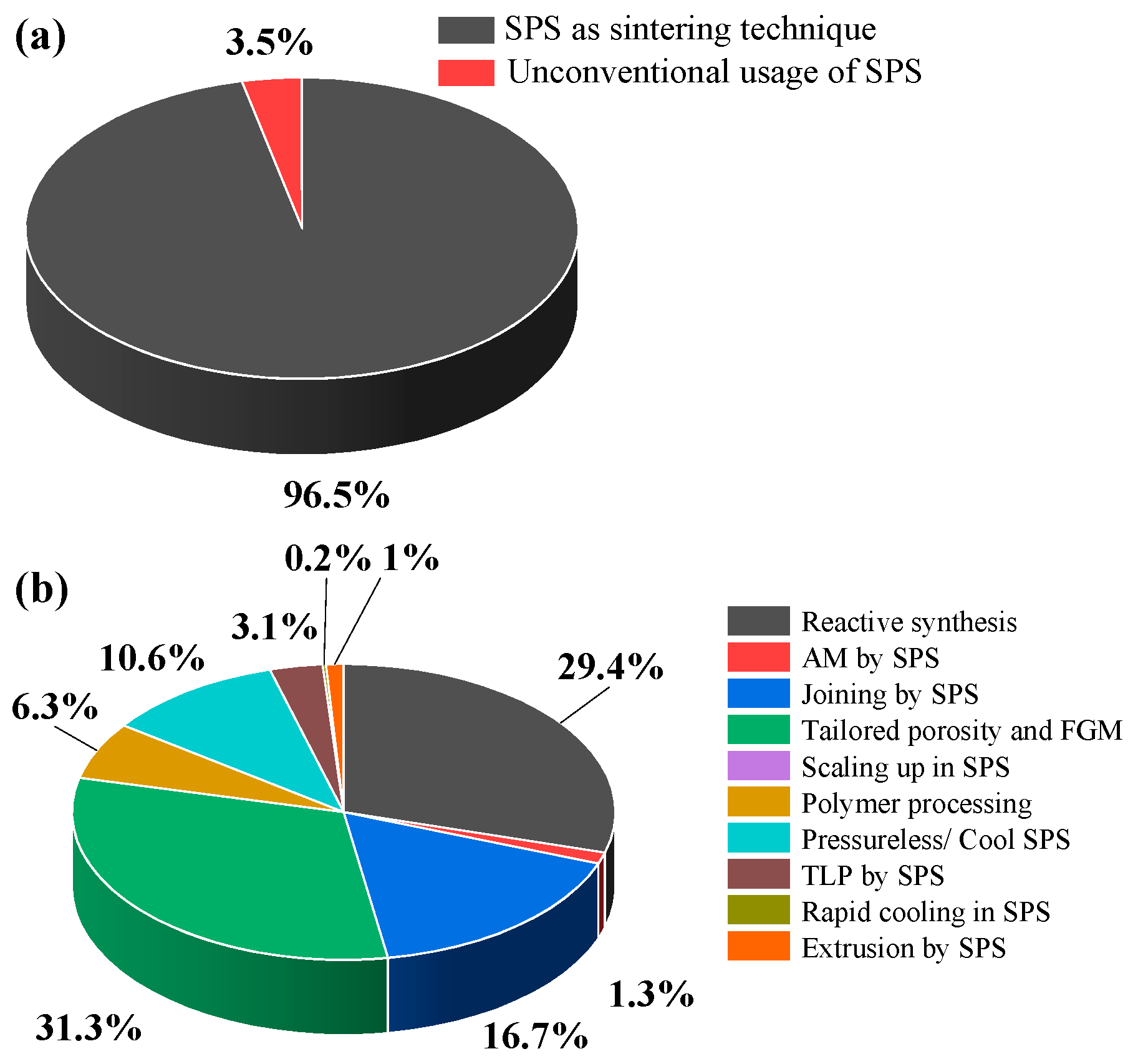
Even if the SPS process is a widely used sintering technique (>96%, see Figure 2a), its usage as a tool to manufacture industrial components is lagging. The two main reasons for this lag are (i) lack of easy scalability and (ii) difficulties in fabricating complex shapes. The classical use of the SPS has been limited to a single sample’s densification with a cylindrical shape. Figure 2 shows a comparison of SPS’ usage as a non-conventional tool, which is less than 4% of its total use. The unconventional usage is further divided into multiple applications (Figure 2b) as recently emerged SPS technique variants. This article describes the SPS technique’s unconventional use in the following sections.
2.1. Reactive Synthesis by SPS
The SPS technique’s significant advantages that will continue to attract researchers, in the long run, include applying pressure, short sintering time, and low sintering temperature. With SPS advancing as a promising rapid consolidating technique for nanostructured powders and composites, it has soon been recognized that chemical reactions can also be performed in SPS so that synthesis and densification can simultaneously be achieved, saving time and adding flexibility to the material’s design. Various materials have been processed using a reactive synthesis (RS) approach via SPS, labeled as RS-SPS. This novel fabrication process for nanocomposites involves molecular-level mixing of raw powders during the reaction process instead of conventional powder mixing. The as-prepared nanocomposites have finer microstructures and exhibit high mechanical properties [14].
Previously, the addition of sintering additives during SPS has been used to improve materials’ densification [15]. However, materials with poor sinterability can be subjected to RS-SPS without using any sintering additives to achieve nearly full densification [16]. RS-SPS is an emerging field that has allowed the processing and densification of high purity refractory ceramics, including ultra-high temperature ceramics (UHTCs) and high-entropy UHTCs at a much lower temperature [17]. RS-SPS’ successes can be further extended by the simultaneous synthesis and joining of two similar or dissimilar materials [18] and the manufacturing of nanostructured coatings [19,20,21].
Microstructure development during RS-SPS involves two processes: (i) simultaneous reaction and densification, and (ii) complete reaction followed by densification (the latter occurs at a higher temperature). The chemical reaction accompanied by shrinkage within a lower temperature range is the best situation for forming dense nanostructured materials [22]. However, the reaction and densification do not always coincide during the RS-SPS. When the reaction ends before the shrinkage starts, one must resort to a higher temperature to obtain a fully dense material. For example, an amorphous mixture of B and C-black tends to form B4C at 1200 °C, while a dense compact of the reaction product is obtained at 1900 °C [23]. Chemical changes in the material during SPS processing can be due to the desired targeted reactions and the undesired formation of new phases. The latter interfacial reaction products are mostly the cause of poor mechanical properties. Such an event was observed in Ti3SiC2-reinforced Cu composites due to the partial melting of the Cu matrix [24].
However, some significant challenges remained in the RS-SPS process. The relationship between the reaction and sintering process, the evolution of phases, densification, and grain growth are not well understood due to limited studies. Thermodynamic modeling of RS-SPS could be one way to predict the formation of different phases during the sintering reaction and grain growth. New synthesis routes can be anticipated to be found for various materials using SPS in its usual design and new geometries in the coming years.
2.2. Additive Manufacturing by SPS
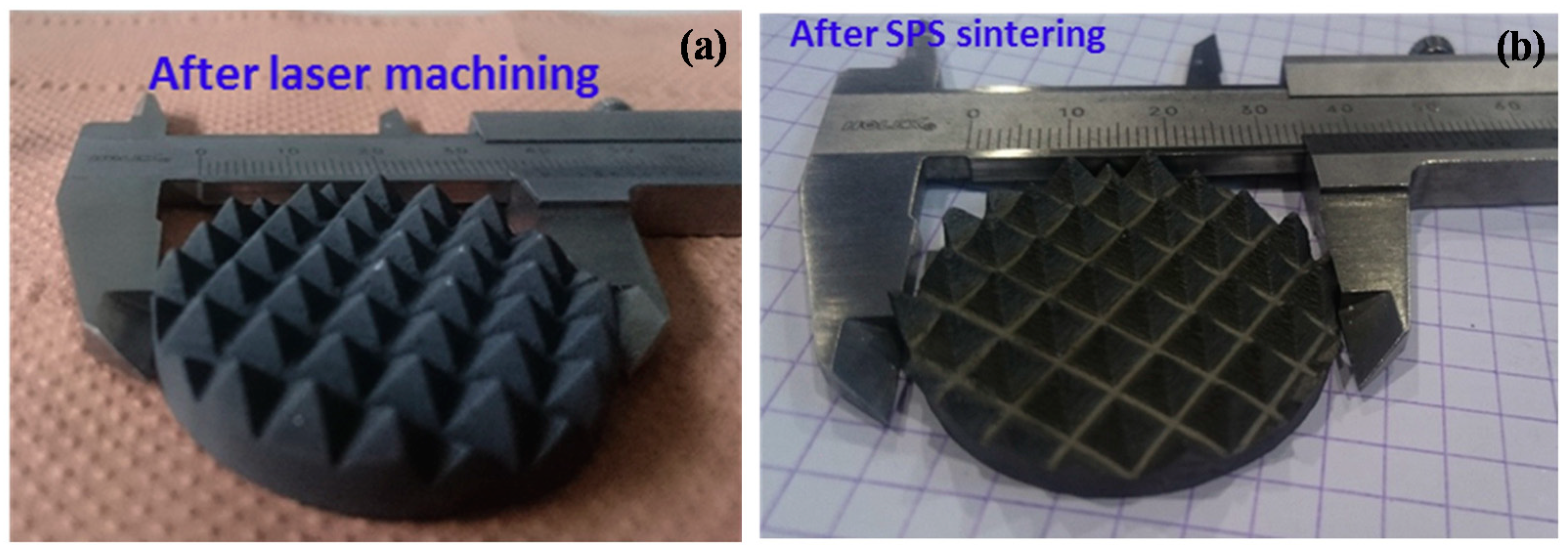
Additive manufacturing (AM) techniques have gained significant attention due to their ability to fabricate complex-shaped components with near full densification and improved mechanical properties. Complex-shaped Al2O3 and WC-12%Co have been processed using SPS without modification of the SPS tool and technique [25]. This study reported a process to sinter a part with complex geometry rapidly, e.g., WC-12%Co were isostatically pressed and subsequently directly laser machined without any heat treatment (green density ~57%). The bushhammer part in WC-12%Co, as shown in Figure 3, was sintered at 1280 °C for 20 min, under 100 kN. The density after sintering was 98%. These parts were prepared by laser machining and sintered in the hybrid SPS furnace (tooling diameter 80 mm) in a TIMREX M150-96 powder bed. The dimensions of the complex component (80 mm) also demonstrate the possibility of scaling up this novel method.
The hybrid approach of utilizing two techniques in the formation of complex geometry has been explored. In this regard, geometrically complex 3D structures of SiC were produced by robocasting, followed by low-pressure SPS to produce a dense structure [26]. The sample displayed >97% of the densification, showing linear shrinkage of ~22.8% from green to the sintered state. Robocasting is a robotic material extrusion process in the AM technique analogous to direct ink writing and other 3D-printing based methods. In this process, a colloidal gel is extruded through a nozzle to form a filament directly deposited in a controlled layer-by-layer sequence into a complex-shaped structure [27]. This approach can provide new avenues to develop complex structures for structural and functional applications.
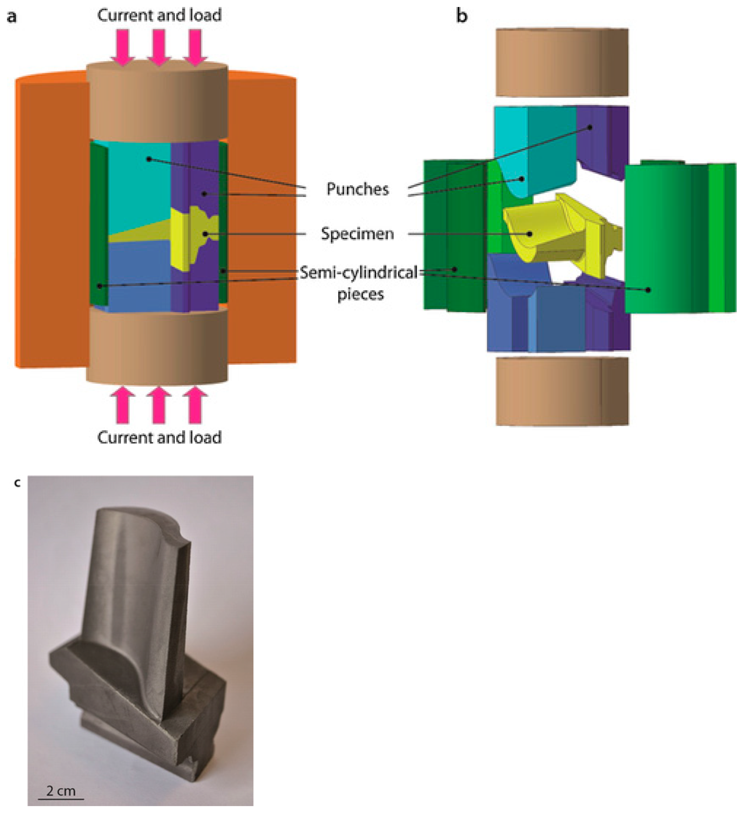
Another complex geometry of a near-net-shape turbine blade has also been successfully sintered using SPS. The γTi-Al alloy was used to produce near-net-shape turbine blades with excellent properties in a single step, both without subsequent thermal treatments [28]. The difficulty of near-net shaping lies in the blade geometry’s complexity with a thin foil and thick root. This can be overcome by modifying the shape and size of the graphite die used for SPS processing. As illustrated in the schematic shown in Figure 4a,b, the modifications were conducted in the graphite mold and punch in shaping the part shown in Figure 4c. The near-net shaped component (Figure 4c) is an 80 mm-long blade with no microstructural heterogeneities observed. Due to the inherent simplicity of the process, such cost-effective modifications represent a breakthrough in the aircraft industry. Furthermore, such work is an outstanding example of how SPS processing can be explored to obtain complex-shaped components in a single step process unobtainable by traditional techniques.
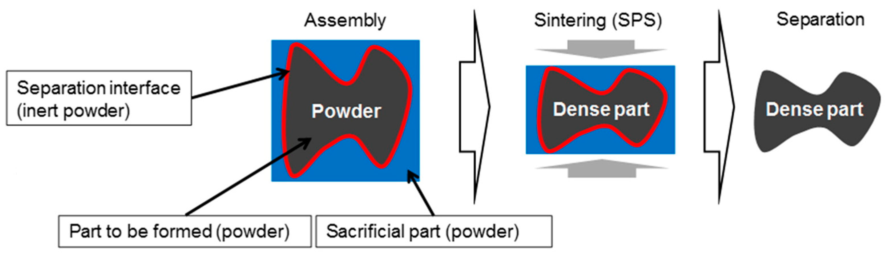
An added challenge of fabricating complex shapes is the thermal gradient and the thickness difference resulting from the geometry. In a complex shape, small thickness areas need lesser punch displacement than the high thickness area. Consequently, in the die compaction process, these small thickness areas densify earlier than the rest of the part, and they block the punches’ displacement, preventing overall densification. In general, the more thickness differences a shape has, the greater the densification inhomogeneity. This can be taken care of by a recently developed innovative approach called the “deformed interfaces method” [29]. In this, an assembly of powders containing a deformable interface allows the post-processing of the complex shape components along with a sacrificial part [29,30]. The assembly is made up of a complex shape porous area lined up with the separation material and surrounded by another sacrificial porous area that is the opposite of the first shape to create an external simple external geometry (of a cylinder). The process is divided into three main steps (see Figure 5): the generation of the porous assembly, the densification of the assembly, and elimination/separation of the sacrificial part. With this simple technique, the possibility of producing multiple pieces using a specifically designed graphite deformable sub-mold can be made possible. Al2O3 powder was inserted at the interface “sample/punches” and Ni was the material to be sintered [30].
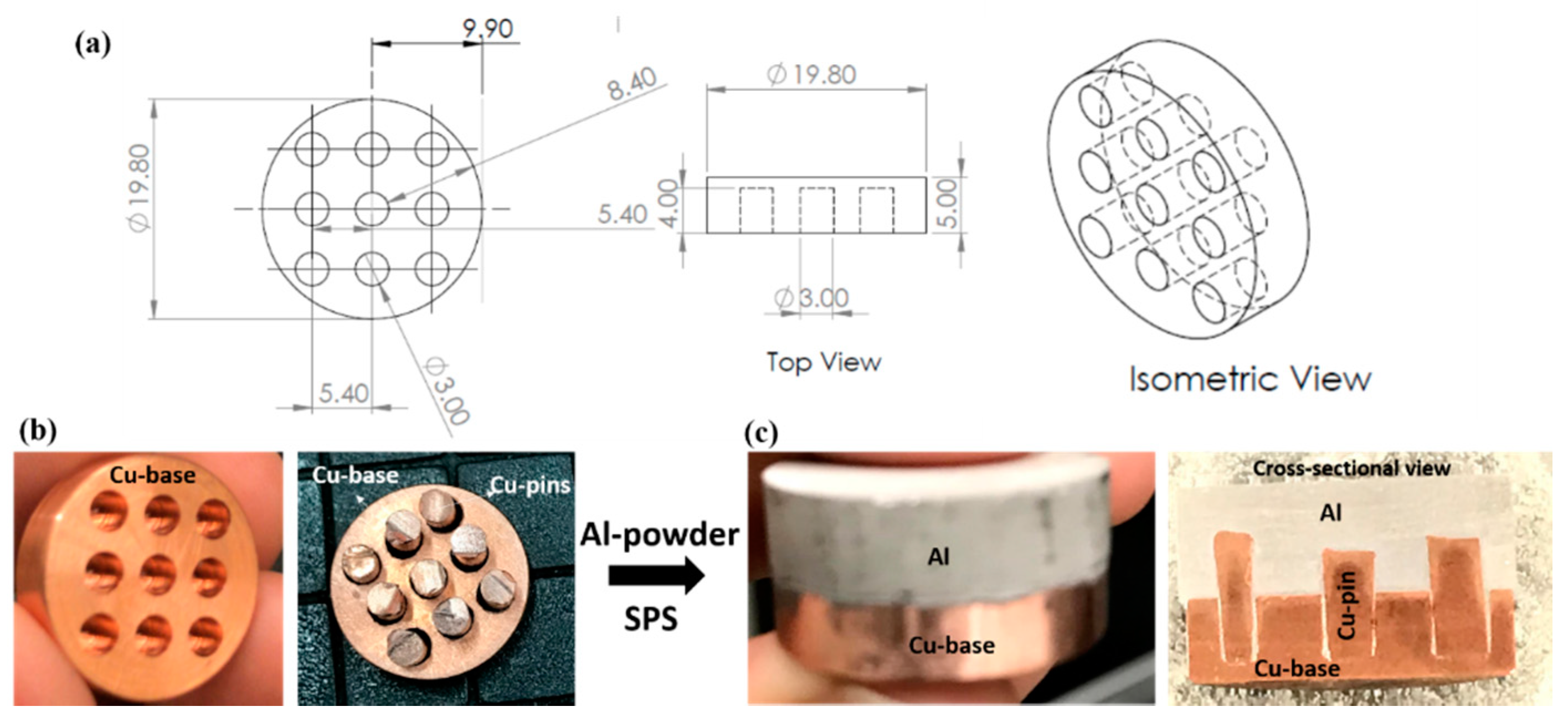
The sound welding between Al and Cu is complicated, mainly due to multiple physical, chemical, and metallurgical properties. Defects such as hot cracks, freezing cracks, and intermetallic compounds appear during the welding process. Because of the recent advances in AM by SPS technique, we fabricated a complex hybrid structure consisting of Curod-Cupins-Alpowder, as shown in the CAD design in Figure 6a, to overcome the problems mentioned above. It should be noted that the potential applications of complex Al-Cu joints are focused on electrical industries as bimetals, bus bars, switchgear, and heat sinks [31]. The images of the overall steps in assembling and SPS of Curod-Cupins-Alpowder are reported in Figure 6b. This involves machining the Cu-rod with an array of cylinders in which Cu pins can be fit. The area within the Cu-rod, Cu-pins, and above in graphite die was filled with Al powders. The assembly was then sintered using SPS. The sample’s cross-sectional view clearly shows the seamlessly joined hybrid and dense structure with each component (Curod, Cupins, and Al), maintaining its design and identity. This experiment highlights the ability of sintering as well as joining three dissimilar materials simultaneously. It would be exciting to look at the microstructure and the gradient in the mechanical and thermal properties at the interfaces of Curod-Cupins-Al.
3. Joining of Materials
Joining is an essential technology for fabricating large as well as complex-shaped components for engineering applications. Lately, SPS has also been used as an innovative technology for joining similar and dissimilar materials with short holding times [32,33,34,35,36,37]. During SPS, the electrical current promotes the diffusion through the joining interface, leading to a strong interfacial bonding strength at the joint. SPS technique has been used to join similar and dissimilar materials, including metals to metals [38], metals to ceramics [39], and metals to polymers [40]. More studies have been conducted on joining ceramics such as α-SiAlON [41], α-SiC [42], ZrB2-SiC [33], C/SiC composites [36], and SiC-graphite [35]. More attention has focused on the choice of filler materials, pressure, and dwell time during joining via SPS.
SPS processing enables the formation of a unique microstructure at the bonding layer, not seen in the joints obtained from conventional techniques [32,43,44]. For a pressureless Ti-Si-C reaction sintering process, a pressureless joining process has also been demonstrated [45]. The study showed that the pressureless joining process is promising for the integration of large, complex-shaped components.
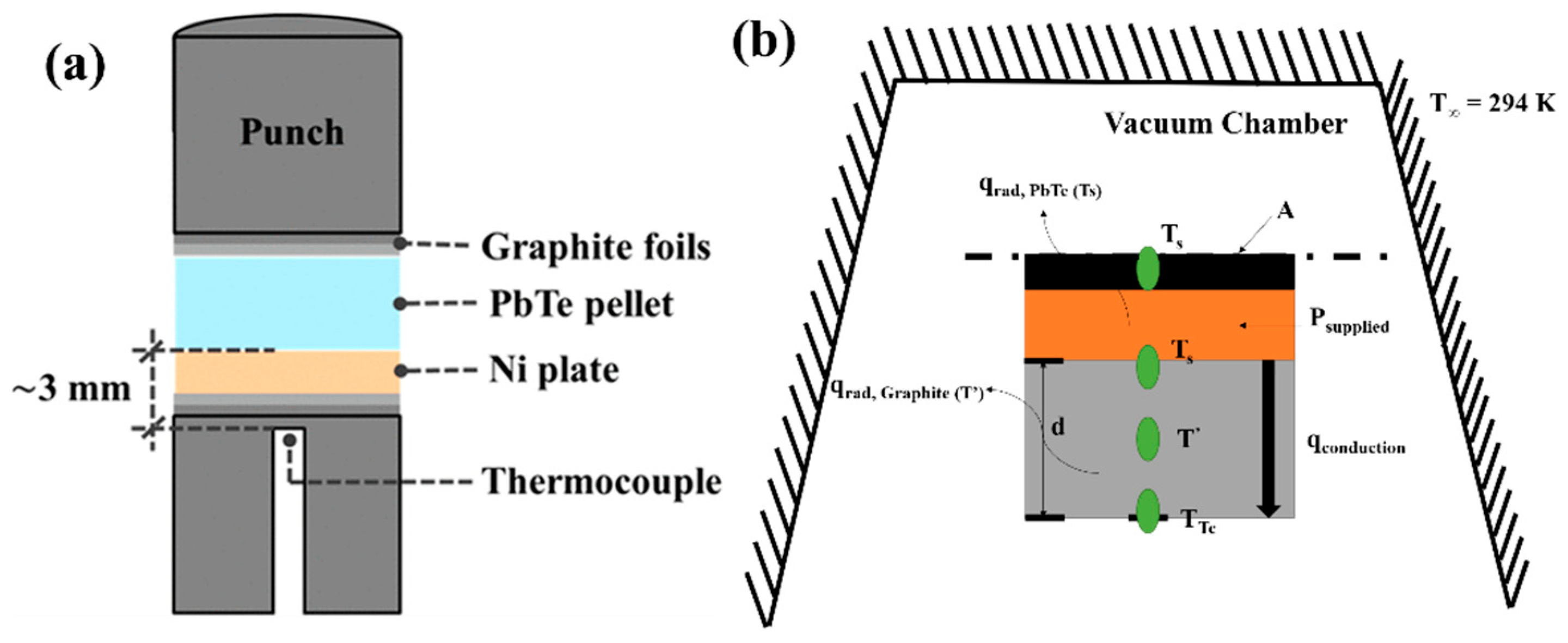
In another study, solid p-type PbTe bulk material was joined to a Ni plate using SPS [46]. The formation of a continuous and defect-free interphase layer of Ni3Te2 was obtained as thin as 4.5 μm when compared to then roughly 27 μm using powder PbTe together with graphite die. The schematic illustration in Figure 7a shows the absence of graphite die, therefore exposing the peripheral surface of two solids in the chamber during the joining process. As a result, radial variation in the interface thickness can occur due to the temperature gradient in the sample’s diameter caused by radiation loss. A one-dimensional thermal model (Figure 7b) was used to determine the sample’s temperature. This approximate model highlights the significant difference of bonding temperatures between the current study and the theoretical temperature of formation for Ni3Te2 (793 K).
The SPS-assisted diffusion joining method has also been used to join refractory ceramics such as ZrB2-SiC substrate using a Zr-B reactive layer as the filler material [33]. Indistinguishable microstructure, mechanical, and oxidation properties at the joint were obtained, comparable to that of the bulk material. However, the coefficient of thermal expansion (CTE) mismatch between the filler material and parent material results in residual stress at the interface. Thus, it results in insufficient strength at the joint and cannot be used above 1400 °C [33]. The filler materials produce a large reaction zone, porosity, and inhomogeneous microstructure across the joint, resulting in reduced strength. New advancements with the joining process where adding filler materials can be omitted will overcome this issue. Future research focused on the joining mechanism, joint properties at service temperature, and numerical simulations to delineate the influencing factors and process optimization is needed. SPS joining techniques have a very high potential in manufacturing hybrid structures and further research is required to exploit the field for practical applications.
4. Tailored Porosity by SPS
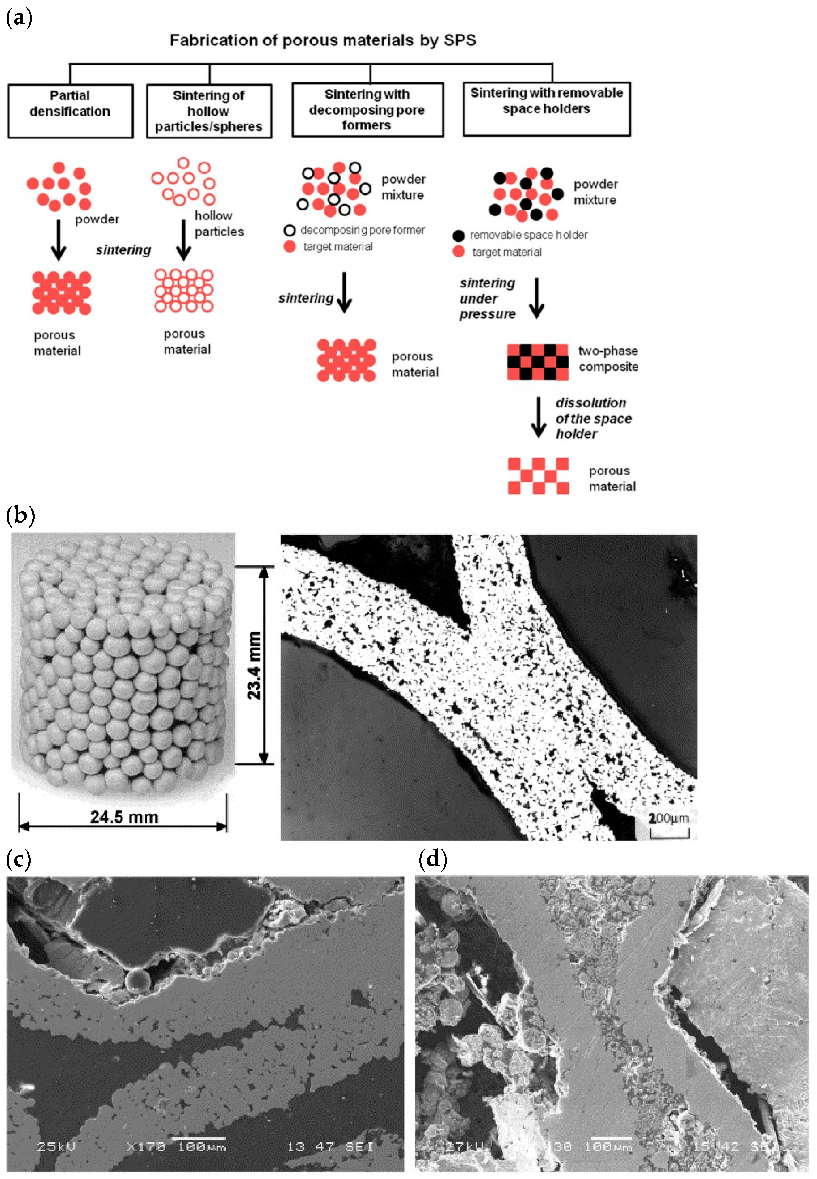
SPS has always been known to utilize pulsed current and pressure to obtain fine-grained microstructure while eliminating porosity. However, recently, the potential of SPS towards fabricating porous materials has also been recognized. SPS devices’ flexibility in heating/cooling and heating mode choices has helped achieve this. This section will highlight the successes and formulate unresolved problems in this area. Various porous metals, intermetallics, alloys, ceramics, and C-based materials have been processed using SPS by the partial densification approach [47]. The following significant methods include pressureless sintering, sintering at low temperature, sintering of hollow and porous structures, and sintering with removable holders to form porous materials. Furthermore, the improvements in porous structures’ performance and reliability via controlling the pore geometry have also been reported [48]. The fabrication approaches and structure formation of the porous material by the SPS process are schematically shown in Figure 8a [47].
The fabrication of porous structures by SPS has shown potential in energy absorption materials, bio-implants, high-temperature filters, fuel cells, and thermoelectric materials. The metallic hollow spheres have gained many critical industrial applications such as lightweight constructions, crash absorbers, heat insulators, and sound absorbers. Several attempts were made to fabricate randomly packed hollow sphere (RHS) structures [49,50,51]. However, due to the extraordinary cost, none of the approaches have gained practical significance. RHS of 316L stainless steel with a ball diameter of 2–3 mm and a wall thickness of 250 m was densified using SPS in the temperature range of 1000–1250 °C, presented in Figure 8b [52]. The as-received RHS has micropores of few micrometers. After SPS processing at 1100 and 1200 °C only for 3 minutes, RHS becomes densified (see Figure 8c) [52]. Porous aluminum is a promising energy-absorption material [53]. In contrast, porous Ti-based alloys and porous metallic glasses are designed to become biocompatible materials [54,55] due to high corrosion and wear resistance [56]. Porous ceramics processed via SPS have been recommended for water and air purifications [57]. SPS has shown promising results for making porous fuel cells [58]. The properties of thermoelectric materials can be tuned by varying porosity as a structural key parameter [59]. In this study [59], Sb-doped Mg2Si0.5Sn0.5 was prepared using pressureless SPS. Compared with dense samples, those with a porosity of 37% showed a significantly lower thermal conductivity and a higher Seebeck coefficient.
The challenge in making porous structures from powders is preserving their porosity; in some cases, the particles’ structure achieves good mechanical integrity. Future investigations are needed to understand the electric current on the mechanical properties of the porous sintered materials. The high heating rates can be beneficial for forming porous structures. SPS with space holders and processing of hollow spheres involves controlling the microstructure of the pore walls.
5. Batch vs. Continuous Process Scale-Up of SPS
The majority of the SPS literature usually focuses on ceramic specimens not larger than 40 mm. This section will demonstrate how new extensions, hybrid or flash technology, and suitable systems can lead to industrial production materials’ essential scaling up. Researchers focus on scaling up the SPS technique to fabricate large-sized specimens approaching 100 mm in diameter and 20 mm in height [60]. Analysis of the densification process, structure evolution, homogeneity, and change in the mechanical properties that arise during the scaling-up of high-temperature ceramics consolidated at temperatures >1800 °C needs to be addressed.
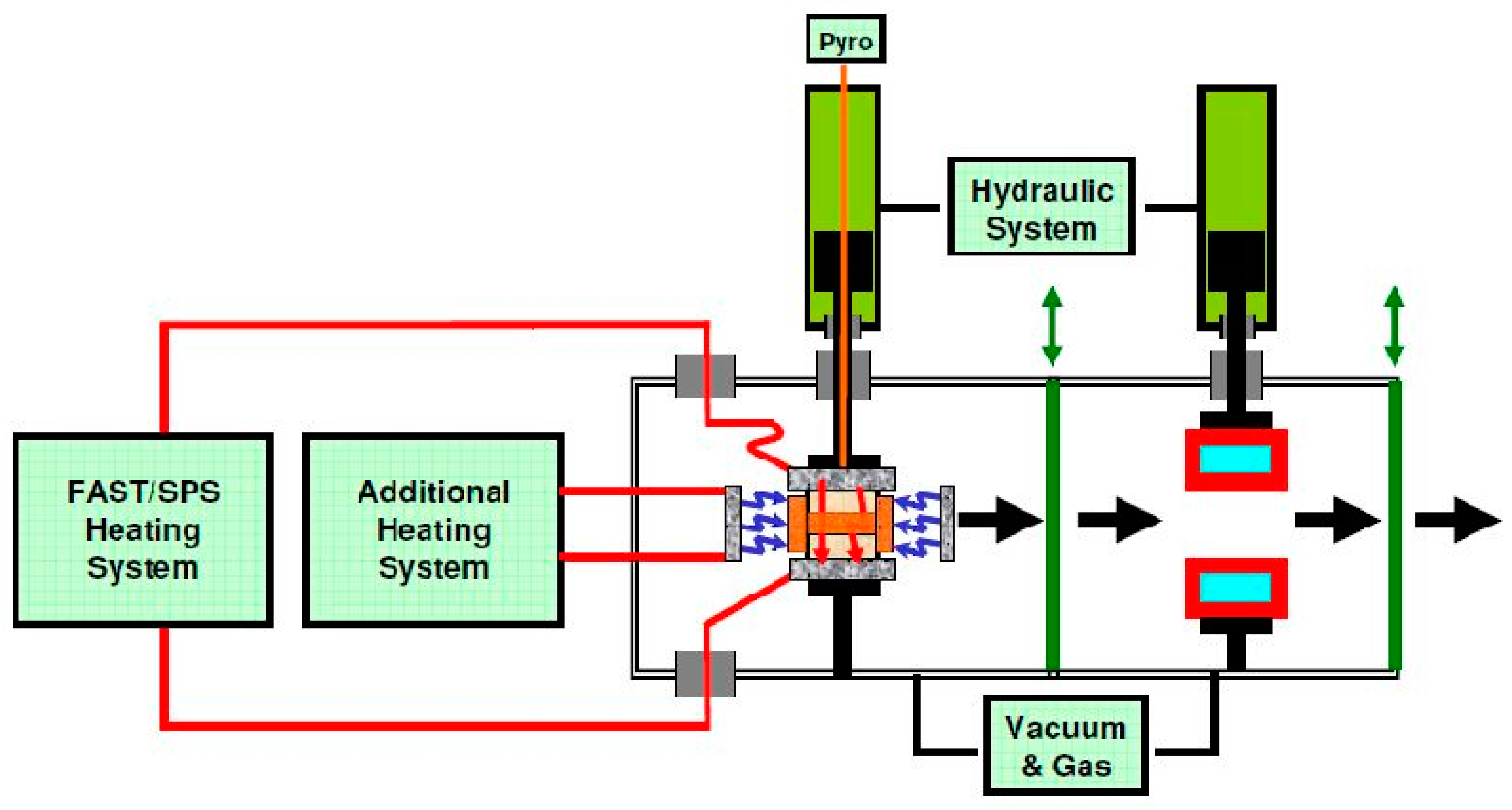
Many companies have tried developing new methods to improve SPS’ results and reduce the time consumed to produce objects. FTC Systeme GmbH developed FAST/SPS (Field Assisted Sintering Technology SPS), Semicontinuous FAST/SPS, Continuous FAST/SPS, FAST2/SPS, and Multiple-pressing tools methods aiming to produce large scalable industrial machines. These FAST methods (e.g., FAST/SPS, FAST/Hybrid, FAST/Flash) allow for a significant heating period reduction due to increased heating rates and thermal homogeneity. Even with these modifications, the long cooling time is still a concern regarding its productivity and cost-efficiency [61]. The semicontinuous process resulted in a favorable change for the industry, but it still requires time for the sample to cool down. The other modification for scaling up the SPS process is that the continuous method [62] comprises a separate preheating of the pressing tool inside a preheating tunnel. This process is significant as it reduces the densification time while simultaneously optimizing the components’ homogeneity. The throughput of such a system can be as high as six pieces per minute, depending on the sintering profile and the material’s size under processing. While the continuous process reduced the time consumed even more, with no wasted time for the sample to cool down, it demands a large space to fit the machine. Another modification is “hybrid heating”, which is a combination of the FAST/SPS method, as illustrated in Figure 9 [63]. It comprises one or several other heating systems, which usually act outside the pressing tool system. The hybrid process improves the samples’ homogeneity, while the semicontinuous process reduced the time consumed to produce samples. For even faster results, other improvements (FAST2/SPS and Multiple-pressing tools) can enable a new market and promotes technical progress to the various application sectors.
Moreover, concerning SPS’ productivity aspect, one of the most promising solutions is multiple parts sintering. The simultaneous sintering of multiple samples has been tried [64] but is difficult to control without optimized configurations. The most significant limitation of this is the maintenance of temperature homogeneity. This needs to be looked upon as a future aspect of the industrialization of the SPS technique. Homogenization can be achieved by adjusting the electric insulations to the current flow and a few geometrical modifications.
6. Polymer Processing via SPS
Polymers have been processed conventionally using techniques such as injection molding or extrusion. However, these techniques have drawbacks as they require high temperatures and melting of the polymers. A few polymers’ high viscosity in the molten state restricts their shape, forming ability, and use of specific fillers such as carbon or aramid fibers [65]. Additionally, high-temperature processing leads to oxidative degradation and crystallization that occurs during the cooling process. This leads to shrinkage problems due to the difference in the density between the amorphous and crystalline phases. A solution to these problems is developing samples by the powder metallurgy approach and, more precisely, via SPS. SPS helps to overcome the challenge of high melt viscosity in polymers. High density and purity are observed in SPS-processed polymers. Moreover, polymers processed using SPS have better mechanical and thermoelectric properties over extrusion and molding. Nevertheless, the origin of remarkable mechanical properties observed without complete melting of polymers remains poorly understood.
Sebileau et al. [66] demonstrated the processing of PEEK below its melting temperature by SPS, in which pressure appeared to be a critical factor that governed the mechanical properties. The pressure applied during sintering played a dual role. The high pressure applied during sintering improved the ductility but is not conducive to obtaining high compressive modulus and high yield strength values. This effect becomes more prominent with an increase in temperature. The negative impact of pressure on PEEK’s mechanical properties has already been reported [67,68]. Wool et al. [67] showed that though a minimum pressure is required to promote the intimate contact and wetting of the interfaces, pressure increase leads to decreased fracture energy of the grain interface. This has been attributed to the fact that at high pressures, polymers’ glass transition temperature increases drastically, which could significantly impact the welding rates at low temperatures.
The development of multi-layered polymeric/metallic materials, referred to as functionally graded materials (FGM) employing SPS, has also been explored [40]. In this study [40], the aim was to join polymers with metal for advanced structural applications. Omori et al. [69] obtained Cu/polyimide (PI) FGMs using a customized die to create a temperature difference between Cu and PI components. A dense three-layered FGM with no cracks and pores was obtained in the study. Thus, processing polymers and composites via SPS is a novel approach that takes care of the issues above, such as chemical degradation and high viscosity, while processing polymers and enhancing their crystallinity and mechanical integrity.
7. Pressureless and Cold-SPS
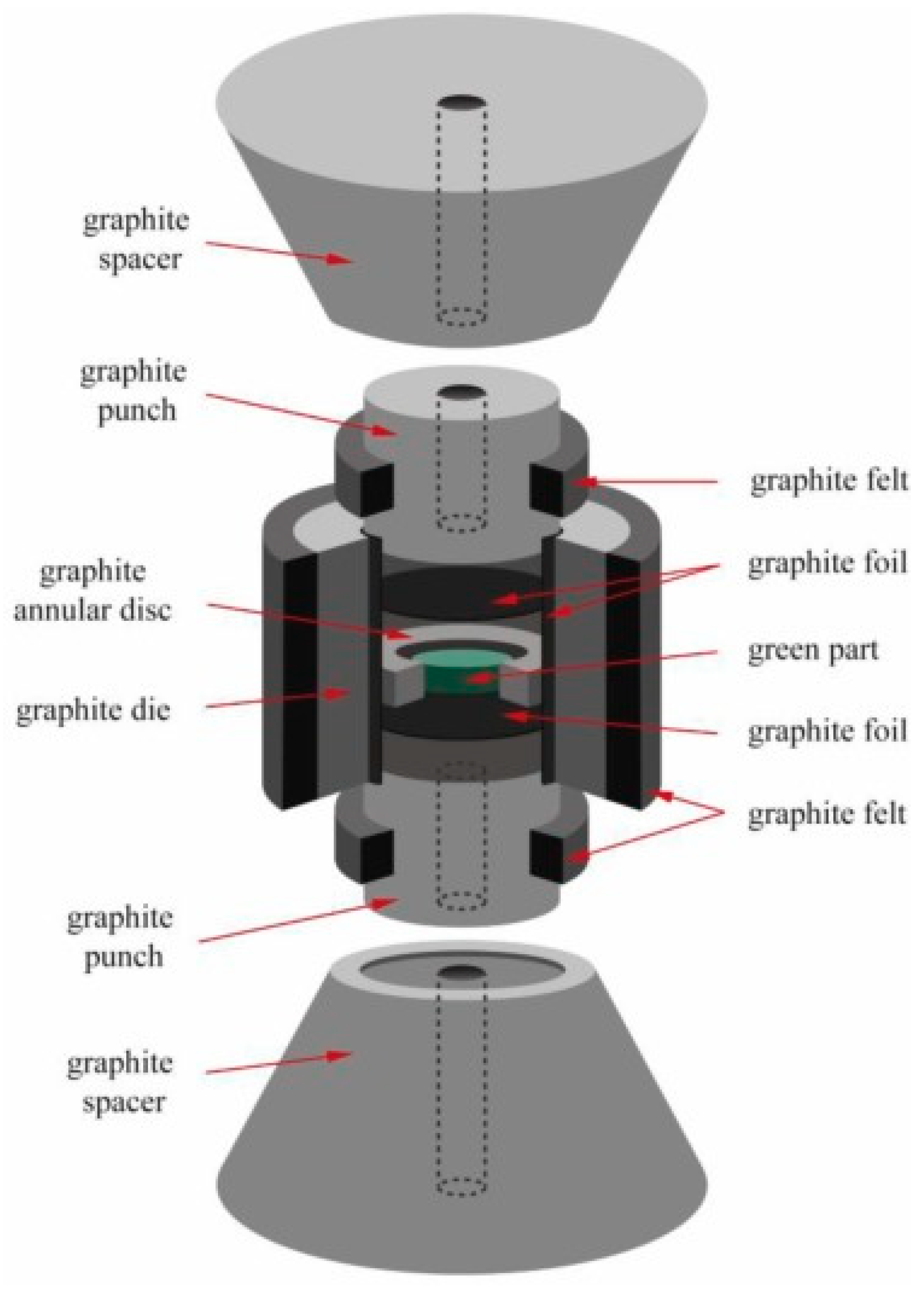
Pressureless sintering has been regarded as the method which has the fewest shape limitations. To obtain this, studies are being conducted to create conventional pressureless sintering conditions inside SPS. A unique feature of this compared to that of the conventional approach is that this process enables rapid and highly homogeneous heating by radiation heat transfer. There are various design modifications used in the literature on the punches instead of regular cylindrical punches. One of such designs is shown in Figure 10 [70]. In the modified punch design, the working space remained constant between the punches by not touching the sample inside the standard SPS die, resulting in zero external pressure. Guintini et al. [71] detailed the process and heating mechanism of pressureless SPS. The electric current goes to the punch through the graphite die and causes an increase in the die temperature due to the Joule heating effect. This generated heat is transferred to the powder inside the die mainly by thermal conduction. The default load of the SPS required for maintaining the die assembly is sustained by the top and bottom surface of the two punches, and thus the powder compact is not subjected to any external pressure [72].
The usage of SPS as a pressureless technique can be divided into three categories:
- Retained grain growth for enhanced mechanical properties;
- Production of a highly porous structure with controlled pore shape, size, and geometry;
- Consolidation of the green body within a short time.
This can be achieved by modified die assembly, which serves as a barrier between loose powder and the graphite SPS die. In this case, neck formation is achieved by the high heating rates, an advantage of using SPS over conventional heating mechanisms. The final temperature and time also play an essential role in the component’s overall shrinkage and final porosity. In some cases, pre-compacted samples are inserted in the SPS die to be sintered via a pressureless approach. The highly densified sample with fine grain structure due to reaching the maximum sintering temperature can be achieved in a very short time. There is limited research on pressureless SPS.
The recent development of the cold sintering process has also been successfully reported, leading to a high densification level while operating from RT to 200 °C [73,74,75]. SPS has been successfully used at relatively low temperatures to consolidate biomaterials [76] and geological disposal of 129I, i.e., lodoapatites [77]. Various thermodynamically fragile compounds such as carbonates, sulfates, and phosphates decomposing between 220 and 780 °C have also been processed using SPS [78]. This enabled the processing of fragile materials easier as these materials have limited thermodynamic stability due to low-temperature decomposition and phase transition. In this regard, relatively high pressure (300 to 600 MPa) and low temperature (below 400 °C) during SPS is used. In literature, this technique has been referred to as “Cool-SPS” to obtain highly dense functional ceramics [78]. The technique led to the formation of highly dense (95–98%) thermodynamically fragile materials. The efficiency of Cool-SPS and its contribution to widening the opportunities associated with low-temperature sintering has been highlighted. The specific case of Na2Cu(CO3)2 obtained through in situ dehydration in the study shows that Cool-SPS can be used to isolate a specific phase that may not be obtained using conventional routes [78]. The sintering of MnSO4 was performed at 400 °C (well below the decomposition temperature of 780 °C), showing that effective sintering can be achieved at low temperatures. This also raises the question if the SPS processing temperature of traditional functional materials (such as oxides) can be lowered. Thus, combining low-temperature traits, extremely short sintering time, and phase stabilization beyond the usual stability range offers vast possibilities for the prospective search of new functional materials and allows for their development.
8. Liquid Phase Sintering by SPS
The sintering process is broadly divided into liquid- and solid-state sintering depending on the state of the sintering additives (or reinforcements), which it undergoes during the sintering process. The former has the advantage of lower sintering temperature, fine grain microstructure, and enhanced strength over the latter. In many refractory materials, especially in ceramics, the strong covalent bonding and low self-diffusion coefficients restrict its densification over grain coarsening. Hence, liquid-state sintering is preferred over solid-state sintering for such materials. For example, solid-state B4C is hard, brittle, and has coarse microstructure undesirable in strength and wear resistance. However, liquid-state sintered B4C has a fine microstructure and is tough, but the residual intragranular phase limits its hardness. This dichotomy can be overcome by using solid-state and liquid state sintering traits referred to as the transient liquid phase (TLP) sintering approach [79]. In TLP sintering, the sintering aid first melts at an early stage of sintering, and then that liquid reacts with the solid, disappearing as sintering proceeds further. This approach has been applied to B4C using metallic and intermetallic sintering additives [80,81].
The transient liquid phase sintering process involves three stages: liquid phase formation and particle re-arrangements, solution re-precipitation, solid-state diffusion, and coarsening. Of these, solid re-precipitation is the most crucial step for the densification step [82] as it is affected by the liquid phase’s viscosity. The liquid phase’s fluidity is further dependent on the sintering temperature and external pressure applied during SPS processing. Using the same liquid-phase sintering additives, different sintering methods would not lead to the same sintering result [83].
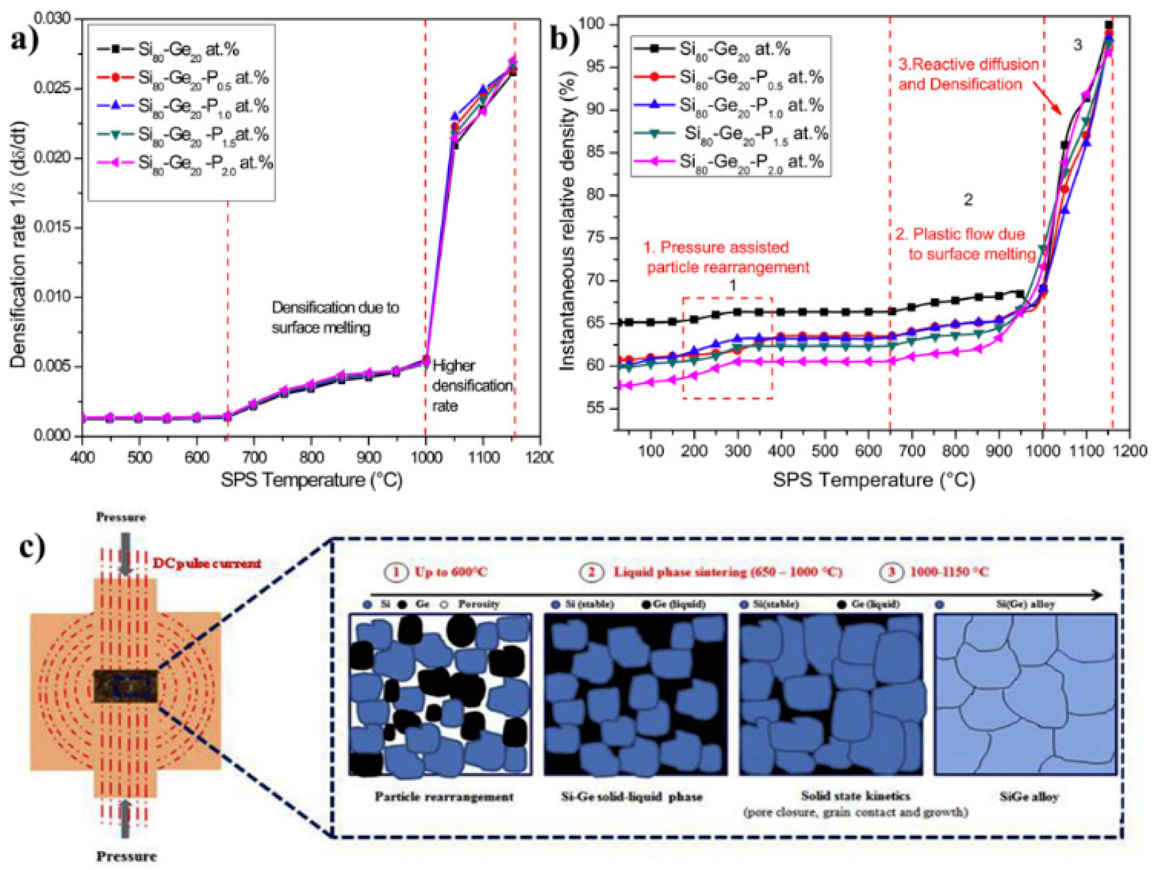
SPS-assisted TLP sintering of a SiGe alloy doped with phosphorous [84] is a rapid and effective method to synthesize SiGe alloys with superior chemical homogeneity and desirable power factor performance. During transient phase SPS, the temperature and pressure provide key contributions for simultaneous in situ alloying and densification. As shown in Figure 11a,b, when the temperature reaches 650 °C, the surface of Ge melts and forms a thin amorphous layer that offers particles to glide and enhances densification. Furthermore, an increase in temperature results in Ge’s complete melting with the co-existence of solid Si particles. In this regime, the applied pressure provides the capillary attraction and superior wettability, resulting in predominant enhancement of liquidus Ge diffusion into stable Si. The schematic representation of this phenomenon is shown in Figure 11c. It was also demonstrated that B4C-MoSi2 powder mixture during TLP sintering led to B4C-MoSi2-SiC triplex particulate formation with fine-grained microstructure [79] due to the C-diffusion.
Future research needs to be conducted to investigate the relationship between the processing, microstructure, and properties of the materials processed using the TLP sintering approach. Moreover, the molten phase formed eventually reacts with the C (from graphite), presenting a unique possibility of further improving the toughness of the material via innovative microstructural design. Additionally, the question arises that in the absence of a solid carbon source in the powder mixture, the CO generated in the furnace would react to the molten phase to more refractory carbide in materials like B4C. It is also unclear whether the molten phase will emerge as a residual secondary phase or disappear either by forming a substitutional solid-solution with the matrix or forming a new refractory carbide along with the C-deficient matrix phase. Indeed, new studies answering these questions are expected. Thus, TLP sintering will create future avenues with improved performances, especially in ceramics for extreme environments.
9. Rapid Cooling After SPS
SPS has been known for its remarkable feature of rapid heating rates for consolidating a large variety of advanced structural materials. SPS has a very high heating rate of up to 1000 °C/min, but its cooling rate is prolonged with natural gas or argon gas flooding. Additionally, adjusting the cooling rates has so far faced limitations. The current section discusses the potentials of modified SPS with an integrated novel gas quenching system. This can provide avenues for advanced structural materials, especially metallic systems, to be sintered and directly quenched up.
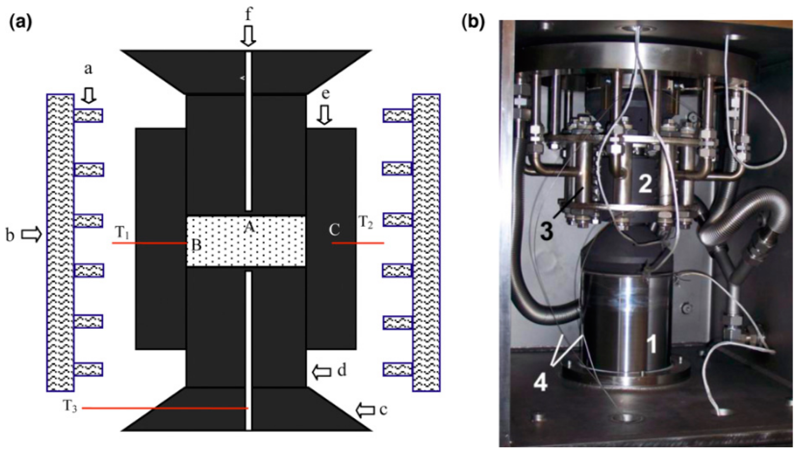
This technique can also be used as a sinter hardening method. The parts are sintered and quenched directly after the sintering step, saving energy and costs connected to conventional hardening where the parts are reheated to hardening temperatures [85,86]. Sinter hardening, when performed by gas quenching instead of oil quenching, has benefits in terms of dimensional stability and cleanliness of the sample. Zhang et al. [87] modified the SPS technique and integrated it with a novel gas quenching system. The SPS vacuum was broken and flooded with argon gas and then quenched with high-velocity nitrogen gas. They investigated the effect of cooling rate on the mechanical properties and microstructures of the Ti6Al4V alloy. The various cooling rates (1.6, 4.8, 5.6, and 6.9 °C/s with an uncertainty of 0.1 °C/s) were achieved by changing the thickness of the graphite dies. The rapid cooling rate has increased the ultimate compressive strength and the compressive strains (ductility) of the Ti6Al4V alloy. Additionally, the hardness (HV1) varied from 327 ± 8, 337 ± 7, 342 ± 4, and 353 ± 4 for cooling rates of 1.6, 4.8, 5.6, and 6.9 °C/s, respectively. The hardness increases with a higher cooling rate; thus, sinter hardening of the Ti6Al4V alloy has been accomplished by gas quenching during SPS. A schematic diagram and image of the gas quenching system in the study’s SPS are shown in Figure 12 [87].
The literature has shown the feasibility of the rapid cooling SPS process and opened the door to processing numerous other metallic powder-based materials systems. The ductility of some alloys can be improved by the rapid cooling rate during SPS. Additionally, this provides the opportunity for the easy manufacturing of complex shapes and plates for engineering applications. However, this technology can probably not be applied to conventional ceramics and other advanced brittle materials.
10. Extrusion by SPS
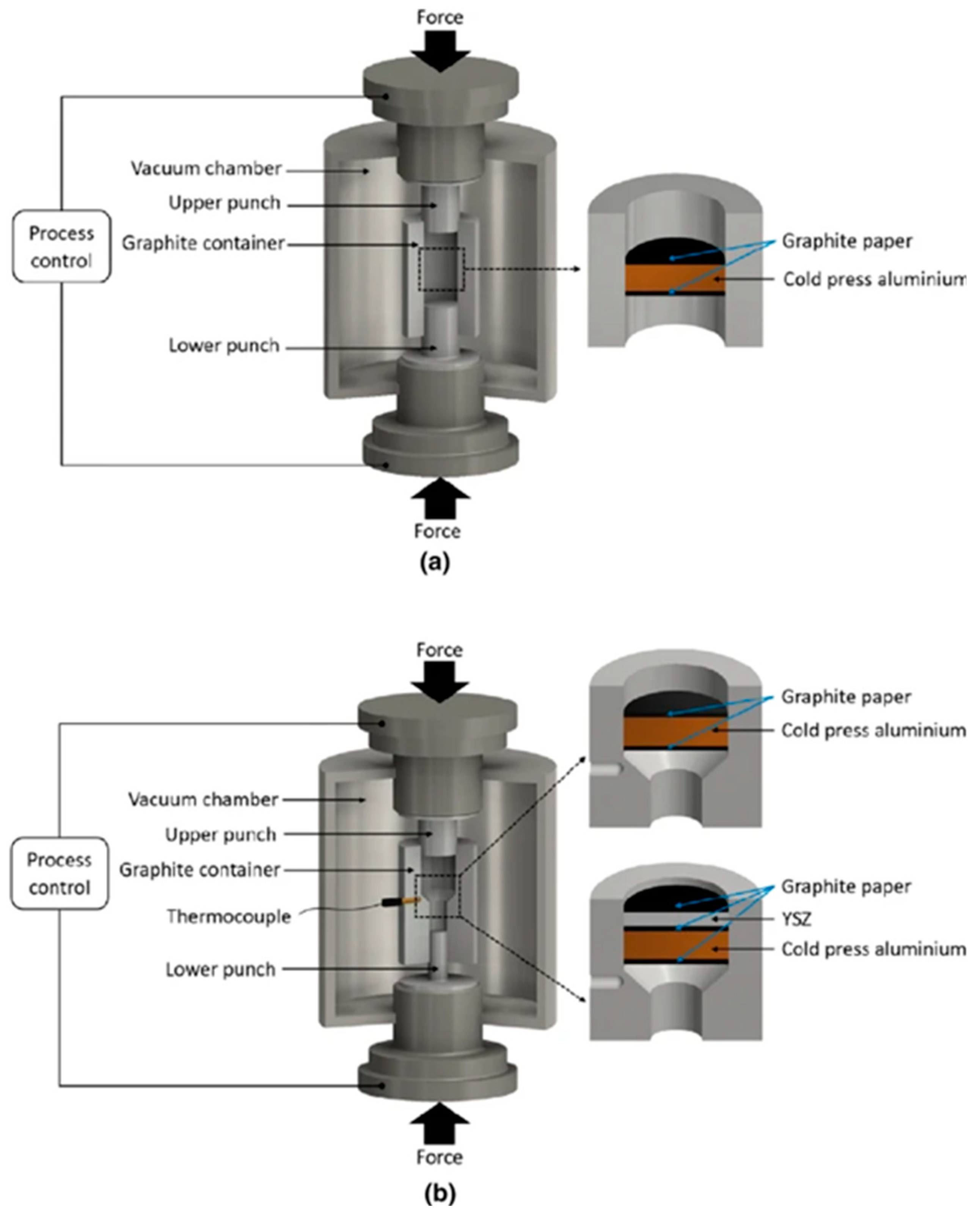
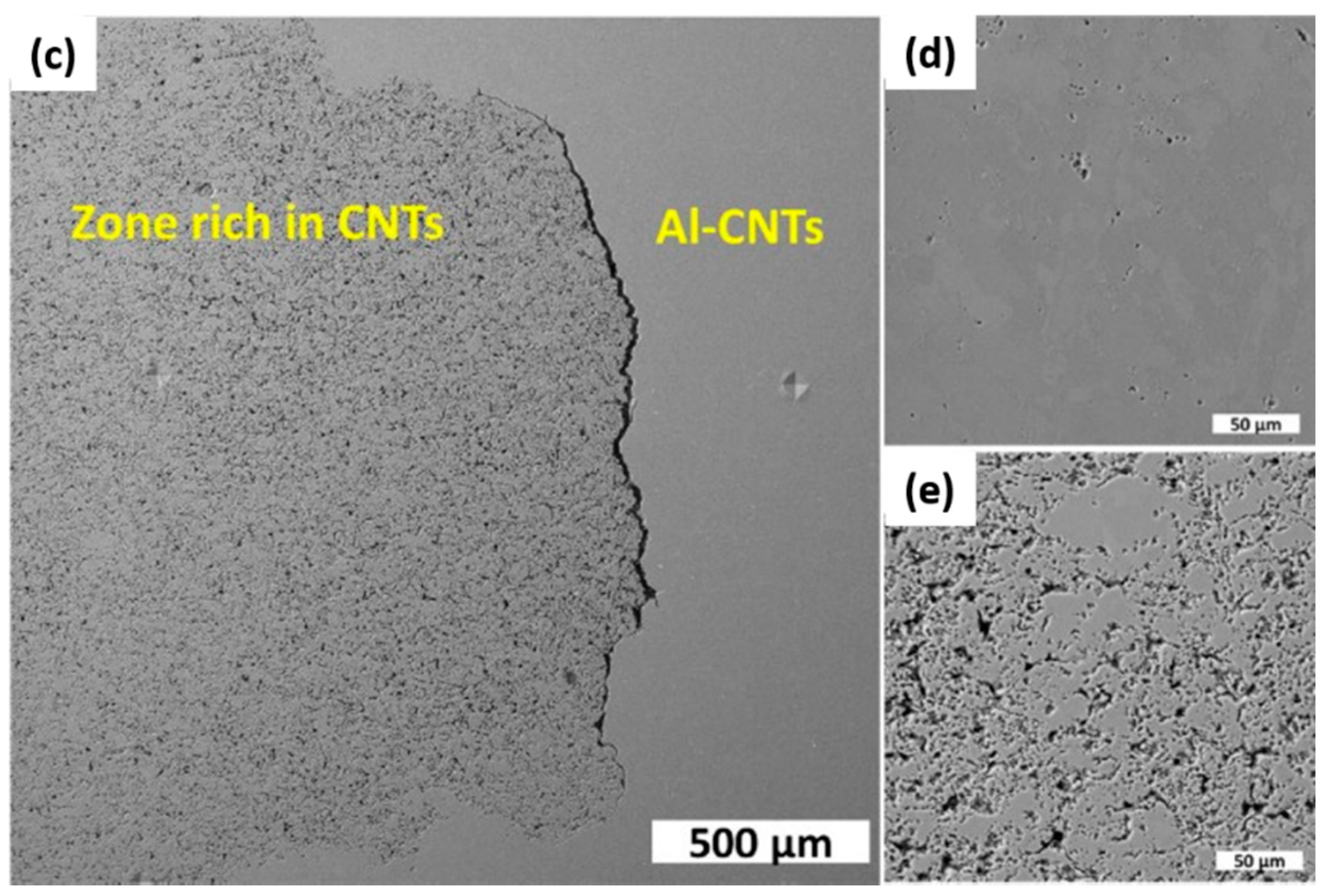
Although SPS has emerged as an advantageous technique for advanced structural materials, it has been limited to simple configuration processing due to its inherent geometric design. However, quite a few studies are highlighting the aspect of the SPS technique for the extrusion process. A few of those studies and the potential of SPS have been described in this section. Extrusion studies on Fe49.7Cr17.7Mn1.9Mo7.4W1.6B15.2C3.8Si2.4 containing Y2O3 nanoparticles, aluminum, and aluminum-carbon nanotube materials systems have recently been reported with the SPS process [88,89,90,91,92]. The spark plasma extrusion (SPE) process’ remarkable advantages over conventional SPS has shown significant implications [93]. This includes faster consolidation, dynamic recrystallization leading to grain refinement due to the electric field, faster kinetics during phase transformation, alignment of the reinforcements in electric field direction, and fabrication of materials with more complex geometries. One example of the graphite die design used during the SPE process is shown in Figure 13 [92]. Al-CNT were cold compressed in an SPS graphite container, as shown in Figure 13a. The cold compressed Al-CNT sample was 10 mm in diameter and 15 mm in height. The modified graphite mold for SPE was designed (Figure 13b) to reduce the diameter from 10 to 5 mm upon exiting the die. The microstructure of the Al-CNT composite produced by the SPE process is shown in Figure 13c–e. The interface between the Al matrix and CNT-rich area is shown in Figure 13c. The Al-rich phase next to the interface (see Figure 13d) has darker dots assigned to the remaining CNT agglomerates. The CNT’s agglomeration in the CNT-rich region in the metal phase melted during SPE is seen in Figure 13e. The EDS analysis showed that the CNT-rich region has 90.4 atomic wt% of C and 5.6 atomic wt% of Al, compared to 7.4 wt% of C and 92.2 wt% of Al in the Al-CNT region.
The idea of combining and SPS requires several questions to be answered and disseminated to the scientific community. These include:
- What is the effect of combined deformation and electric current activation on the recovery and recrystallization behavior of extruding materials?
- What is the effect of current density, extrusion speed, and extrusion ratio on the activation energy for extrusion, deformation mechanisms, extrusion pressure requirements, and resulting microstructures?
- Given that SPE will have different heat generation and dissipation sources (e.g., Joule heating, frictional heating, deformation heating, heat losses to the tooling, and decreased Joule heating during the process due to loss of resistance through consolidation), what would be the temperature distribution within a spark plasma-extruded/extruding sample? Furthermore, how does it affect the microstructure?
The recent innovative research on SPS technology and its extension to extrusion has significant implications in producing powder-based materials of extended geometries. It can also emerge as a technique for generating unique microstructures due to stress-induced deformation under the influence of electric current; the material recrystallization due to the impact of current during extrusion via SPS. Research is also underway to examine the possibility of fabricating nanowires and nanotubes using ultra-high current densities via the SPE process. Future work will explore higher extrusion speed to overcome reduced extrusion temperature with ram displacement of the SPS. It is also expected that the SPE process can be applied to a wide range of materials.
11. Summary
SPS processing’s initial motivation was centered as a fast consolidation technique under electric field and current application. Presently, the range of potential applications from automotive to aerospace to marine and biomedical implants has urged the broadening of horizons for the SPS process. Hence, SPS’ usage from merely a consolidation technique of cylindrical shaped samples has grown considerably with certain tool modifications into a variety of entirely new techniques. It includes RS-SPS, additive manufacturing, joining materials, fabrication of porous structures, scaling-up of SPS processing, polymer processing, pressureless SPS, cold SPS, rapid cooling post-consolidation, TLP processing, and extrusion. A few of these advancements in the SPS technique with their real-life industrial applications have schematically been shown in Figure 14. This illustrates that current, electric fields, and pressure during SPS processing have dramatically enhanced the degree of freedom in materials’ design. Each of these processes has made significant progress, but the lure of revolutionary advances will continue to motivate research on SPS’ unconventional usage. Each of these advancements in SPS technology allows for the easy manufacturing of complex shapes components, hard-to-sinter materials, C-containing materials, interconnected materials, and advanced structural and functional materials. The scaling-up of these complex-shaped components from a lab-scale can also be taken to the next level using modern, production-capable, hybrid, continuous SPS machines for industrial applications. Hence, the global SPS research community should impress upon the non-conventional usage of the SPS technique, highlighting its transition from laboratory scale to real-world applications. However, there still lies the question of whether these complex-shaped components require machining post sintering or not. More complex geometries exhibit new challenges for their machining. The generation of residual stresses post-machining will influence the performance of the final product.
The development of new hybrid sintering by combining different sintering methods, e.g., direct and indirect heating, uniaxial and gas pressure, high and low electric fields, is the next step in SPS technology. Hybrid systems will provide new opportunities for developing and optimizing innovative materials in the intensive research fields of power engineering, electric mobility, or aerospace sectors.
Funding
This research was funded by the Department of Energy grant (DE-NA0003865).
Acknowledgments
The authors acknowledge the Partnership for Research and Education Consortium in Ceramics and Polymers (PRE-CCAP) formed via the Department of Energy grant DE-NA0003865. Advanced Materials Engineering Research Institute (AMERI), FIU is also acknowledged for providing research facilities.
Conflicts of Interest
The authors declare that they have no known competing financial interests or personal relationships that could have appeared to influence the work reported in this paper.
References
- Alaniz, J.; Dupuy, A.; Kodera, Y.; Garay, J. Effects of applied pressure on the densification rates in current-activated pressure-assisted densification (CAPAD) of nanocrystalline materials. Scr. Mater. 2014, 92, 7–10. [Google Scholar] [CrossRef]
- Biswas, K.; He, J.; Blum, I.D.; Wu, C.-I.; Hogan, T.P.; Seidman, D.N.; Dravid, V.P.; Kanatzidis, M.G. High-performance bulk thermoelectrics with all-scale hierarchical architectures. Nature 2012, 489, 414–418. [Google Scholar] [CrossRef] [PubMed]
- Cramer, C.L.; McMurray, J.W.; Lance, M.J.; Lowden, R.A. Reaction-bond composite synthesis of SiC-TiB2 by spark plasma sintering/field-assisted sintering technology (SPS/FAST). J. Eur. Ceram. Soc. 2020, 40, 988–995. [Google Scholar] [CrossRef]
- Garay, J. Current-activated, pressure-assisted densification of materials. Annu. Rev. Mater. Res. 2010, 40, 445–468. [Google Scholar] [CrossRef]
- Hui, G.; Chuan-Bin, W.; Qiang, S.; Lian-Meng, Z. Preparation of La2NiMnO6 double-perovskite ceramics by plasma activated sintering. J. Inorg. Mater. 2019, 34, 541–545. [Google Scholar]
- Liu, Y.; Liebenberg, D. Electromagnetic radio frequency heating in the pulsed electric current sintering (PECS) process. MRS Commun. 2017, 7, 266–271. [Google Scholar] [CrossRef] [Green Version]
- Peigney, A. Tougher ceramics with nanotubes. Nat. Mater. 2003, 2, 15–16. [Google Scholar] [CrossRef]
- Tan, Z.; Wang, L.; Xue, Y.; Zhang, P.; Cao, T.; Cheng, X. High-entropy alloy particle reinforced Al-based amorphous alloy composite with ultrahigh strength prepared by spark plasma sintering. Mater. Des. 2016, 109, 219–226. [Google Scholar] [CrossRef]
- El-Atwani, O.; Quach, D.V.; Efe, M.; Cantwell, P.R.; Heim, B.; Schultz, B.; Stach, E.A.; Groza, J.R.; Allain, J.P. Multimodal grain size distribution and high hardness in fine grained tungsten fabricated by spark plasma sintering. Mater. Sci. Eng. A 2011, 528, 5670–5677. [Google Scholar] [CrossRef]
- Guillon, O.; Gonzalez-Julian, J.; Dargatz, B.; Kessel, T.; Schierning, G.; Räthel, J.; Herrmann, M. Field-assisted sintering technology/spark plasma sintering: Mechanisms, materials, and technology developments. Adv. Eng. Mater. 2014, 16, 830–849. [Google Scholar] [CrossRef]
- Hu, Z.-Y.; Zhang, Z.-H.; Cheng, X.-W.; Wang, F.-C.; Zhang, Y.-F.; Li, S.-L. A review of multi-physical fields induced phenomena and effects in spark plasma sintering: Fundamentals and applications. Mater. Des. 2020, 191, 108662. [Google Scholar] [CrossRef]
- Kelly, J.P.; Graeve, O.A. Spark Plasma Sintering as an Approach to Manufacture Bulk Materials: Feasibility and Cost Savings. JOM 2015, 67, 29–33. [Google Scholar] [CrossRef]
- Musa, C.; Licheri, R.; Locci, A.M.; Orrù, R.; Cao, G.; Rodriguez, M.A.; Jaworska, L. Energy efficiency during conventional and novel sintering processes: The case of Ti–Al2O3–TiC composites. J. Clean. Prod. 2009, 17, 877–882. [Google Scholar] [CrossRef]
- Dudina, D.V.; Mukherjee, A.K. Reactive spark plasma sintering: Successes and challenges of nanomaterial synthesis. J. Nanomater. 2013, 2013, 625218. [Google Scholar] [CrossRef]
- Nguyen, V.-H.; Asl, M.S.; Mahaseni, Z.H.; Germi, M.D.; Delbari, S.A.; Van Le, Q.; Ahmadi, Z.; Shokouhimehr, M.; Namini, A.S.; Mohammadi, M. Role of co-addition of BN and SiC on microstructure of TiB2-based composites densified by SPS method. Ceram. Int. 2020, 46, 25341–25350. [Google Scholar] [CrossRef]
- Gild, J.; Kaufmann, K.; Vecchio, K.; Luo, J. Reactive flash spark plasma sintering of high-entropy ultrahigh temperature ceramics. Scr. Mater. 2019, 170, 106–110. [Google Scholar] [CrossRef]
- Nisar, A.; Zhang, C.; Boesl, B.; Agarwal, A. A perspective on challenges and opportunities in developing high entropy-ultra high temperature ceramics. Ceram. Int. 2020, 46, 25845–25853. [Google Scholar] [CrossRef]
- Liu, W.; Naka, M. In situ joining of dissimilar nanocrystalline materials by spark plasma sintering. Scr. Mater. 2003, 48, 1225–1230. [Google Scholar] [CrossRef]
- Matsubara, T.; Shibutani, T.; Uenishi, K.; Kobayashi, K.F. Fabrication of TiB2 reinforced Al3Ti composite layer on Ti substrate by reactive-pulsed electric current sintering. Mater. Sci. Eng. A 2002, 329, 84–91. [Google Scholar] [CrossRef]
- Mulukutla, M.; Singh, A.; Harimkar, S.P. Spark plasma sintering for multi-scale surface engineering of materials. JOM 2010, 62, 65–71. [Google Scholar] [CrossRef]
- Singh, A.; Bakshi, S.R.; Virzi, D.A.; Keshri, A.K.; Agarwal, A.; Harimkar, S.P. In-situ synthesis of TiC/SiC/Ti3SiC2 composite coatings by spark plasma sintering. Surf. Coat. Technol. 2011, 205, 3840–3846. [Google Scholar] [CrossRef]
- Munir, Z. Synthesis and densification of nanomaterials by mechanical and field activation. J. Mater. Synth. Process. 2000, 8, 189–196. [Google Scholar] [CrossRef]
- Anselmi-Tamburini, U.; Munir, Z.A.; Kodera, Y.; Imai, T.; Ohyanagi, M. Influence of synthesis temperature on the defect structure of boron carbide: Experimental and modeling studies. J. Am. Ceram. Soc. 2005, 88, 1382–1387. [Google Scholar] [CrossRef] [Green Version]
- Dudina, D.V.; Mali, V.I.; Anisimov, A.G.; Bulina, N.V.; Korchagin, M.A.; Lomovsky, O.I.; Bataev, I.A.; Bataev, V.A. Ti 3 SiC 2-Cu composites by mechanical milling and Spark Plasma Sintering: Possible microstructure formation scenarios. Met. Mater. Int. 2013, 19, 1235–1241. [Google Scholar] [CrossRef]
- Hocquet, S.; Dupont, V.; Cambier, F.; Ludewig, F.; Vandewalle, N. Densification of complex shape ceramics parts by SPS. J. Eur. Ceram. Soc. 2020, 40, 2586–2596. [Google Scholar] [CrossRef]
- Cai, K.; Román-Manso, B.; Smay, J.E.; Zhou, J.; Osendi, M.I.; Belmonte, M.; Miranzo, P. Geometrically Complex Silicon Carbide Structures Fabricated by Robocasting. J. Am. Ceram. Soc. 2012, 95, 2660–2666. [Google Scholar] [CrossRef]
- Duoss, E.B.; Twardowski, M.; Lewis, J.A. Sol-Gel Inks for Direct-Write Assembly of Functional Oxides. Adv. Mater. 2007, 19, 3485–3489. [Google Scholar] [CrossRef]
- Voisin, T.; Monchoux, J.-P.; Durand, L.; Karnatak, N.; Thomas, M.; Couret, A. An Innovative Way to Produce γ-TiAl Blades: Spark Plasma Sintering. Adv. Eng. Mater. 2015, 17, 1408–1413. [Google Scholar] [CrossRef]
- Manière, C.; Nigito, E.; Durand, L.; Weibel, A.; Beynet, Y.; Estournes, C. Spark plasma sintering and complex shapes: The deformed interfaces approach. Powder Technol. 2017, 320, 340–345. [Google Scholar] [CrossRef] [Green Version]
- Manière, C.; Torresani, E.; Olevsky, E.A. Simultaneous spark plasma sintering of multiple complex shapes. Materials 2019, 12, 557. [Google Scholar] [CrossRef] [Green Version]
- Bakhtiari Argesi, F.; Shamsipur, A.; Mirsalehi, S.E. Dissimilar Joining of Pure Copper to Aluminum Alloy via Friction Stir Welding. Acta Metall. Sin. 2018, 31, 1183–1196. [Google Scholar] [CrossRef] [Green Version]
- Dong, H.; Yu, Y.; Jin, X.; Tian, X.; He, W.; Ma, W. Microstructure and mechanical properties of SiC-SiC joints joined by spark plasma sintering. Ceram. Int. 2016, 42, 14463–14468. [Google Scholar] [CrossRef]
- Pinc, W.R.; Di Prima, M.; Walker, L.S.; Wing, Z.N.; Corral, E.L. Spark plasma joining of ZrB2–SiC composites using zirconium–boron reactive filler layers. J. Am. Ceram. Soc. 2011, 94, 3825–3832. [Google Scholar] [CrossRef]
- Yu, Y.; Dong, H.; Ma, B.; Ren, Q.; Ma, W. Effect of different filler materials on the microstructure and mechanical properties of SiCSiC joints joined by spark plasma sintering. J. Alloys Compd. 2017, 708, 373–379. [Google Scholar] [CrossRef]
- Okuni, T.; Miyamoto, Y.; Abe, H.; Naito, M. Joining of silicon carbide and graphite by spark plasma sintering. Ceram. Int. 2014, 40, 1359–1363. [Google Scholar] [CrossRef]
- Rizzo, S.; Grasso, S.; Salvo, M.; Casalegno, V.; Reece, M.J.; Ferraris, M. Joining of C/SiC composites by spark plasma sintering technique. J. Eur. Ceram. Soc. 2014, 34, 903–913. [Google Scholar] [CrossRef]
- Zhou, X.; Liu, J.; Zou, S.; Xu, K.; Chang, K.; Li, P.; Huang, F.; Huang, Z.; Huang, Q. Almost seamless joining of SiC using an in-situ reaction transition phase of Y3Si2C2. J. Eur. Ceram. Soc. 2020, 40, 259–266. [Google Scholar] [CrossRef]
- Miriyev, A.; Stern, A.; Tuval, E.; Kalabukhov, S.; Hooper, Z.; Frage, N. Titanium to steel joining by spark plasma sintering (SPS) technology. J. Mater. Process. Technol. 2013, 213, 161–166. [Google Scholar] [CrossRef]
- Zhang, Y.; Feng, D.; He, Z.-Y.; Chen, X.-C. Progress in joining ceramics to metals. J. Iron Steel Res. Int. 2006, 13, 1–5. [Google Scholar] [CrossRef]
- Schwertz, M.; Lemonnier, S.; Barraud, E.; Carradò, A.; Vallat, M.-F.; Nardin, M. Spark plasma sintering technology applied to polymer-based composites for structural light weighting. Powder Metall. 2015, 58, 87–90. [Google Scholar] [CrossRef]
- Liu, L.; Ye, F.; Zhou, Y.; Zhang, Z.; Hou, Q. Fast bonding α-SiAlON ceramics by spark plasma sintering. J. Eur. Ceram. Soc. 2010, 30, 2683–2689. [Google Scholar] [CrossRef]
- Grasso, S.; Tatarko, P.; Rizzo, S.; Porwal, H.; Hu, C.; Katoh, Y.; Salvo, M.; Reece, M.J.; Ferraris, M. Joining of β-SiC by spark plasma sintering. J. Eur. Ceram. Soc. 2014, 34, 1681–1686. [Google Scholar] [CrossRef]
- Tatarko, P.; Chlup, Z.; Mahajan, A.; Casalegno, V.; Saunders, T.G.; Dlouhý, I.; Reece, M.J. High temperature properties of the monolithic CVD β-SiC materials joined with a pre-sintered MAX phase Ti3SiC2 interlayer via solid-state diffusion bonding. J. Eur. Ceram. Soc. 2017, 37, 1205–1216. [Google Scholar] [CrossRef]
- Koyanagi, T.; Katoh, Y.; Hinoki, T.; Henager, C.; Ferraris, M.; Grasso, S. Progress in development of SiC-based joints resistant to neutron irradiation. J. Eur. Ceram. Soc. 2020, 40, 1023–1034. [Google Scholar] [CrossRef]
- Koyanagi, T.; Katoh, Y.; Kiggans, J.; Hinoki, T.; Khalifa, H.; Deck, C.; Back, C. Irradiation resistance of silicon carbide joint at light water reactor–relevant temperature. J. Nucl. Mater. 2017, 488, 150–159. [Google Scholar] [CrossRef] [Green Version]
- Ferreres, X.R.; Gazder, A.; Manettas, A.; Aminorroaya Yamini, S. Solid-state bonding of bulk PbTe to nickel electrode for thermoelectric modules. ACS Appl. Energy Mater. 2018, 1, 348–354. [Google Scholar] [CrossRef]
- Dudina, D.V.; Bokhonov, B.B.; Olevsky, E.A. Fabrication of porous materials by spark plasma sintering: A review. Materials 2019, 12, 541. [Google Scholar] [CrossRef] [Green Version]
- Hussein, M.A.; Shahzad, H.K.; Patel, F.; Atieh, M.A.; Al-Aqeeli, N.; Baroud, T.N.; Laoui, T. Porous Al2O3-CNT Nanocomposite Membrane Produced by Spark Plasma Sintering with Tailored Microstructure and Properties for Water Treatment. Nanomaterials 2020, 10, 845. [Google Scholar] [CrossRef]
- Andersen, O.; Waag, U.; Schneider, L.; Stephani, G.; Kieback, B. Novel metallic hollow sphere structures: Processing and properties. In Proceedings of the 1st International Conference on Metal Foams and Porous Metal Structures (MetFoam´99), Breme, Germany, 14–16 June 1999; pp. 14–16. [Google Scholar]
- Hurysz, K.; Clark, J.; Nagel, A.; Hardwicke, C.; Lee, K.; Cochran, J.; Sanders, T. Steel and titanium hollow sphere foams. MRS Online Proc. Libr. Arch. 1998, 521. [Google Scholar] [CrossRef]
- Sazegaran, H.; Kiani-Rashid, A.R.; Khaki, J.V. Effects of sphere size on the microstructure and mechanical properties of ductile iron–steel hollow sphere syntactic foams. Int. J. Miner. Metall. Mater. 2016, 23, 676–682. [Google Scholar] [CrossRef]
- Khor, K.A.; Yu, L.G.; Andersen, O.; Stephani, G. Effect of spark plasma sintering (SPS) on the microstructure and mechanical properties of randomly packed hollow sphere (RHS) cell wall. Mater. Sci. Eng. A 2003, 356, 130–135. [Google Scholar] [CrossRef]
- Hakamada, M.; Yamada, Y.; Nomura, T.; Chen, Y.; Kusuda, H.; Mabuchi, M. Fabrication of porous aluminum by spacer method consisting of spark plasma sintering and sodium chloride dissolution. Mater. Trans. 2005, 46, 2624–2628. [Google Scholar] [CrossRef] [Green Version]
- Yamanoglu, R.; Gulsoy, N.; Olevsky, E.; Gulsoy, H. Production of porous Ti5Al2. 5Fe alloy via pressureless spark plasma sintering. J. Alloys Compd. 2016, 680, 654–658. [Google Scholar] [CrossRef] [Green Version]
- Nicula, R.; Lüthen, F.; Stir, M.; Nebe, B.; Burkel, E. Spark plasma sintering synthesis of porous nanocrystalline titanium alloys for biomedical applications. Biomol. Eng. 2007, 24, 564–567. [Google Scholar] [CrossRef] [PubMed]
- Xie, G.; Fukuhara, M.; Louzguine-Luzgin, D.V.; Inoue, A. Ultrasonic characteristics of porous Zr55Cu30Al10Ni5 bulk metallic glass fabricated by spark plasma sintering. Intermetallics 2010, 18, 2014–2018. [Google Scholar] [CrossRef]
- Akhtar, F.; Vasiliev, P.O.; Bergström, L. Hierarchically porous ceramics from diatomite powders by pulsed current processing. J. Am. Ceram. Soc. 2009, 92, 338–343. [Google Scholar] [CrossRef]
- Stingaciu, M.; Zhu, B.; Singh, M.; Johnsson, M. Single-component fuel cells fabricated by spark plasma sintering. RSC Adv. 2012, 2, 12140–12143. [Google Scholar] [CrossRef]
- Ning, H.; Mastrorillo, G.D.; Grasso, S.; Du, B.; Mori, T.; Hu, C.; Xu, Y.; Simpson, K.; Maizza, G.; Reece, M.J. Enhanced thermoelectric performance of porous magnesium tin silicide prepared using pressure-less spark plasma sintering. J. Mater. Chem. A 2015, 3, 17426–17432. [Google Scholar] [CrossRef] [Green Version]
- Vasylkiv, O. Growing Larger: Scaling up during Spark Plasma Sintering of High—Temperature Ceramics. In Proceedings of the Electric Field Assisted Sintering and Related Phenomena Far from Equilibrium, Tomar, Portugal, 6–11 March 2016. [Google Scholar]
- Hennicke, J.; Kessel, T.; Raethel, J. Enhancements on Fast Sintering Systems Promote Transfer from the Lab to Industrial Applications. In Advanced Processing and Manufacturing Technologies for Nanostructured and Multifunctional Materials III; The American Ceramic Society: Daytona Beach, FL, USA, 2017; pp. 11–20. [Google Scholar]
- Hennicke, J.; Kessel, H.; Kessel, T.; Neeß, H. High-Throughput Serial Production Line for Hot Pressing of Large Area Ceramic Components; The Advanced Materials Show: Birmingham, UK, 2019. [Google Scholar]
- Suárez, M.; Fernández, A.; Menéndez, J.; Torrecillas, R.; Kessel, H.; Hennicke, J.; Kirchner, R.; Kessel, T. Challenges and opportunities for spark plasma sintering: A key technology for a new generation of materials. Sinter. Appl. 2013, 13, 319–342. [Google Scholar]
- Manière, C.; Durand, L.; Weibel, A.; Chevallier, G.; Estournès, C. A sacrificial material approach for spark plasma sintering of complex shapes. Scr. Mater. 2016, 124, 126–128. [Google Scholar] [CrossRef]
- Adesina, O.T.; Sadiku, E.R.; Jamiru, T.; Ogunbiyi, O.F.; Adesina, O.S. Thermal properties of spark plasma-sintered polylactide/graphene composites. Mater. Chem. Phys. 2020, 242, 122545. [Google Scholar] [CrossRef]
- Sébileau, J.C.; Lemonnier, S.; Barraud, E.; Vallat, M.F.; Carradò, A.; Nardin, M. Consolidation by spark plasma sintering (SPS) of polyetheretherketone. J. Appl. Polym. Sci. 2017, 134, 44911. [Google Scholar] [CrossRef]
- Wool, R.P.; Yuan, B.L.; McGarel, O. Welding of polymer interfaces. Polym. Eng. Sci. 1989, 29, 1340–1367. [Google Scholar] [CrossRef]
- Blaiszik, B.J.; Kramer, S.L.; Olugebefola, S.C.; Moore, J.S.; Sottos, N.R.; White, S.R. Self-healing polymers and composites. Annu. Rev. Mater. Res. 2010, 40, 179–211. [Google Scholar] [CrossRef]
- Omori, M.; Okubo, A.; Kang, G.; Hirai, T. Preparation and properties of polyimide/Cu functionally graded material. In Proceedings of the 4th International Symposium on Functionally Graded Materials, Tsukuba, Japan, 21–24 October 1996; Elsevier Science: Tsukuba, Japan, 1997; pp. 767–772. [Google Scholar]
- Ojalvo, C.; Moreno, R.; Guiberteau, F.; Ortiz, A.L. Pressureless ultrafast sintering of near-net-shaped superhard isotropic B4C/rGO composites with Ti-Al additives. J. Eur. Ceram. Soc. 2020, 40, 4354–4360. [Google Scholar] [CrossRef]
- Giuntini, D.; Wei, X.; Maximenko, A.L.; Wei, L.; Ilyina, A.M.; Olevsky, E.A. Initial stage of free pressureless spark-plasma sintering of vanadium carbide: Determination of surface diffusion parameters. Int. J. Refract. Met. Hard Mater. 2013, 41, 501–506. [Google Scholar] [CrossRef]
- Yamanoglu, R. Pressureless Spark Plasma Sintering: A Perspective from Conventional Sintering to Accelerated Sintering Without Pressure. Powder Metall. Met. Ceram. 2019, 57, 513–525. [Google Scholar] [CrossRef]
- Guo, J.; Berbano, S.S.; Guo, H.; Baker, A.L.; Lanagan, M.T.; Randall, C.A. Cold sintering process of composites: Bridging the processing temperature gap of ceramic and polymer materials. Adv. Funct. Mater. 2016, 26, 7115–7121. [Google Scholar] [CrossRef]
- Guo, H.; Baker, A.; Guo, J.; Randall, C.A. Cold sintering process: A novel technique for low-temperature ceramic processing of ferroelectrics. J. Am. Ceram. Soc. 2016, 99, 3489–3507. [Google Scholar] [CrossRef]
- Guo, H.; Baker, A.; Guo, J.; Randall, C.A. Protocol for ultralow-temperature ceramic sintering: An integration of nanotechnology and the cold sintering process. ACS Nano 2016, 10, 10606–10614. [Google Scholar] [CrossRef]
- Grossin, D.; Rollin-Martinet, S.; Estournès, C.; Rossignol, F.; Champion, E.; Combes, C.; Rey, C.; Geoffroy, C.; Drouet, C. Biomimetic apatite sintered at very low temperature by spark plasma sintering: Physico-chemistry and microstructure aspects. Acta Biomater. 2010, 6, 577–585. [Google Scholar] [CrossRef] [PubMed] [Green Version]
- Yao, T.; Scott, S.; Xin, G.; Lu, F.; Lian, J. Dense Iodoapatite ceramics consolidated by low-temperature spark plasma sintering. J. Am. Ceram. Soc. 2015, 98, 3733–3739. [Google Scholar] [CrossRef]
- De Beauvoir, T.H.; Sangregorio, A.; Cornu, I.; Elissalde, C.; Josse, M. Cool-SPS: An opportunity for low temperature sintering of thermodynamically fragile materials. J. Mater. Chem. C 2018, 6, 2229–2233. [Google Scholar] [CrossRef] [Green Version]
- Ojalvo, C.; Guiberteau, F.; Ortiz, A.L. Fabricating toughened super-hard B4C composites at lower temperature by transient liquid-phase assisted spark plasma sintering with MoSi2 additives. J. Eur. Ceram. Soc. 2019, 39, 2862–2873. [Google Scholar] [CrossRef]
- Ji, W.; Todd, R.I.; Wang, W.; Wang, H.; Zhang, J.; Fu, Z. Transient liquid phase spark plasma sintering of B4C-based ceramics using Ti-Al intermetallics as sintering aid. J. Eur. Ceram. Soc. 2016, 36, 2419–2426. [Google Scholar] [CrossRef]
- Ortiz, A.L.; Candelario, V.M.; Moreno, R.; Guiberteau, F. Near-net shape manufacture of B4C–Co and ZrC–Co composites by slip casting and pressureless sintering. J. Eur. Ceram. Soc. 2017, 37, 4577–4584. [Google Scholar] [CrossRef] [Green Version]
- German, R.M.; Suri, P.; Park, S.J. Review: Liquid phase sintering. J. Mater. Sci 2009, 44, 1–39. [Google Scholar] [CrossRef] [Green Version]
- Liang, H.; Yao, X.; Huang, Z.; Zeng, Y.; Su, B. Effect of sintering techniques on the microstructure of liquid-phase-sintered SiC ceramics. J. Eur. Ceram. Soc. 2016, 36, 1863–1871. [Google Scholar] [CrossRef]
- Murugasami, R.; Vivekanandhan, P.; Kumaran, S.; Kumar, R.S.; Tharakan, T.J. Thermoelectric power factor performance of silicon-germanium alloy doped with phosphorus prepared by spark plasma assisted transient liquid phase sintering. Scr. Mater. 2018, 143, 35–39. [Google Scholar] [CrossRef]
- Thakur, S.N.; Newkirk, J.W.; Fillari, G.B.; Murphy, T.F.; Narasimhan, K. Mechanical properties of sinter-hardened steels. Int. J. Powder Metall. 2004, 40, 45–54. [Google Scholar]
- Dlapka, M.; Danninger, H.; Gierl, C.; Lindqvist, B. Sinter hardening—A special heat treatment for powder metallurgy precision parts. HTM J. Heat Treat. Mater. 2012, 67, 223. [Google Scholar] [CrossRef]
- Zhang, F.; Reich, M.; Kessler, O.; Burkel, E. The potential of rapid cooling spark plasma sintering for metallic materials. Mater. Today 2013, 16, 192–197. [Google Scholar] [CrossRef]
- Hallett, R.; Cox, J.R.; Morsi, K. Novel Spark Plasma Extrusion of Titanium Above and Below the β-Transus: Effect on Microstructure and Properties. Metall. Mater. Trans. B 2020, 51, 1363–1369. [Google Scholar] [CrossRef]
- Novitskaya, E.; Esquivel-Castro, T.; Dieguez-Trejo, G.; Kritsuk, A.; Cahill, J.; Díaz-de-la-Torre, S.; Graeve, O. Current assisted extrusion of metallic alloys: Insight into microstructure formation and mechanical properties. Mater. Sci. Eng. A 2018, 717, 62–67. [Google Scholar] [CrossRef]
- Morsi, K.; Esawi, A.; Borah, P.; Lanka, S.; Sayed, A.; Taher, M. Properties of single and dual matrix aluminum–carbon nanotube composites processed via spark plasma extrusion (SPE). Mater. Sci. Eng. A 2010, 527, 5686–5690. [Google Scholar] [CrossRef]
- Morsi, K.; Esawi, A.; Lanka, S.; Sayed, A.; Taher, M. Spark plasma extrusion (SPE) of ball-milled aluminum and carbon nanotube reinforced aluminum composite powders. Compos. Part A Appl. Sci. Manuf. 2010, 41, 322–326. [Google Scholar] [CrossRef]
- Čelko, L.; Menelaou, M.; Casas-Luna, M.; Horynová, M.; Musálek, T.; Remešová, M.; Diaz-De-La-Torre, S.; Morsi, K.; Kaiser, J. Spark Plasma Extrusion and the Thermal Barrier Concept. Metall. Mater. Trans. B 2019, 50, 656–665. [Google Scholar] [CrossRef]
- Morsi, K.; El-Desouky, A.; Johnson, B.; Mar, A.; Lanka, S. Spark plasma extrusion (SPE): Prospects and potential. Scr. Mater. 2009, 61, 395–398. [Google Scholar] [CrossRef]
Figure 1.
(a) Schematic representation of the spark plasma sintering (SPS) equipment and (b) SPS mechanism.
Figure 1.
(a) Schematic representation of the spark plasma sintering (SPS) equipment and (b) SPS mechanism.

Figure 2.
Pie chart on the publications related to the SPS process (a) as a sintering tool vs. unconventional usage, and (b) the relative distribution of unconventional processing by SPS (based on data collected from the Web of Science). Here, FGM stands for Functionally Graded Materials, and TLP stands for Transient Liquid Phase.

Figure 3.
Photograph of the bushhammer part in WC-12%Co (a) before and (b) after SPS. Reproduced with permission from reference [25].
Figure 3.
Photograph of the bushhammer part in WC-12%Co (a) before and (b) after SPS. Reproduced with permission from reference [25].

Figure 4.
Schematic of the SPS graphite mold (a) punch in their final positions, (b) exploded view of the mold eliciting how punches and pieces give its shape to the blade, and (c) near-net-shape blade obtained from the process. Reproduced with permission from reference [28].
Figure 4.
Schematic of the SPS graphite mold (a) punch in their final positions, (b) exploded view of the mold eliciting how punches and pieces give its shape to the blade, and (c) near-net-shape blade obtained from the process. Reproduced with permission from reference [28].

Figure 5.
Schematic illustrating three main steps in the deformed interfaces method: assembly, sintering, and sacrificial part. Reproduced with permission from Reference [29].
Figure 5.
Schematic illustrating three main steps in the deformed interfaces method: assembly, sintering, and sacrificial part. Reproduced with permission from Reference [29].

Figure 6.
Complex hybrid structure of Curod-Cupins-Alpowder (a) CAD design, (b,c) overall steps involved in machining, assembling, and SPS. The cross-sectional view of the complex and dense hybrid structure of Curod-Cupins-Al has also been presented in (c).
Figure 6.
Complex hybrid structure of Curod-Cupins-Alpowder (a) CAD design, (b,c) overall steps involved in machining, assembling, and SPS. The cross-sectional view of the complex and dense hybrid structure of Curod-Cupins-Al has also been presented in (c).

Figure 7.
(a) Experimental assembly for bonding between PbTe and Ni solids (reproduced with permissions from reference [46]), and (b) One-dimensional thermal model for the bonding process of current assembly in the SPS (Concept adapted and redrawn from [46]).

Figure 8.
(a) Schematic illustrating approaches to the fabrication of porous materials by SPS. Open re-prints from reference [47], (b) Outline and optical micrograph of the randomly packed hollow sphere before SPS, and SEM micrographs of randomly packed hollow sphere SPS treated at (c) 1100 °C and (d) 1200 °C. Reproduced with permission from reference [52].

Figure 9.
Schematic illustrating the concept of an industrial high throughput sintering system. Open re-prints from reference [63].
Figure 9.
Schematic illustrating the concept of an industrial high throughput sintering system. Open re-prints from reference [63].

Figure 10.
Schematic illustration of the experimental assembly of the graphite tools used for pressureless-SPS. Reproduced with permission from reference [70].
Figure 10.
Schematic illustration of the experimental assembly of the graphite tools used for pressureless-SPS. Reproduced with permission from reference [70].

Figure 11.
Si-Ge powder (a) densification rate, (b) instantaneous relative density during SPS, and (c) schematic representation of alloying in SPS. Reproduced with permission from reference [84].
Figure 11.
Si-Ge powder (a) densification rate, (b) instantaneous relative density during SPS, and (c) schematic representation of alloying in SPS. Reproduced with permission from reference [84].

Figure 12.
(a) Schematic illustrating modifications in the SPS chamber with the gas quenching system. Herein, a: gas nozzles, b: gas tube. C: graphite cone, d: graphite punch, e: graphite foam, f: pyrometer hole for temperature measurement at position A; T1, T2, and T3 are the thermocouples to measure sample temperatures, respectively, at position B, graphite foam C, and graphite cone. (b) Photograph of the SPS chamber. Reproduced with permission from reference [87].

Figure 13.
Schematic of the graphite die used for (a) cold pressing the Al-CNT green body, and (b) position of the sample before the spark plasma extrusion process. The microstructure of the Al-CNT composite produced by SPE process (c) interface of Al and CNT, (d) Al-rich region next to the interface, and (e) CNT-rich region. Reproduced with permission from reference [92].


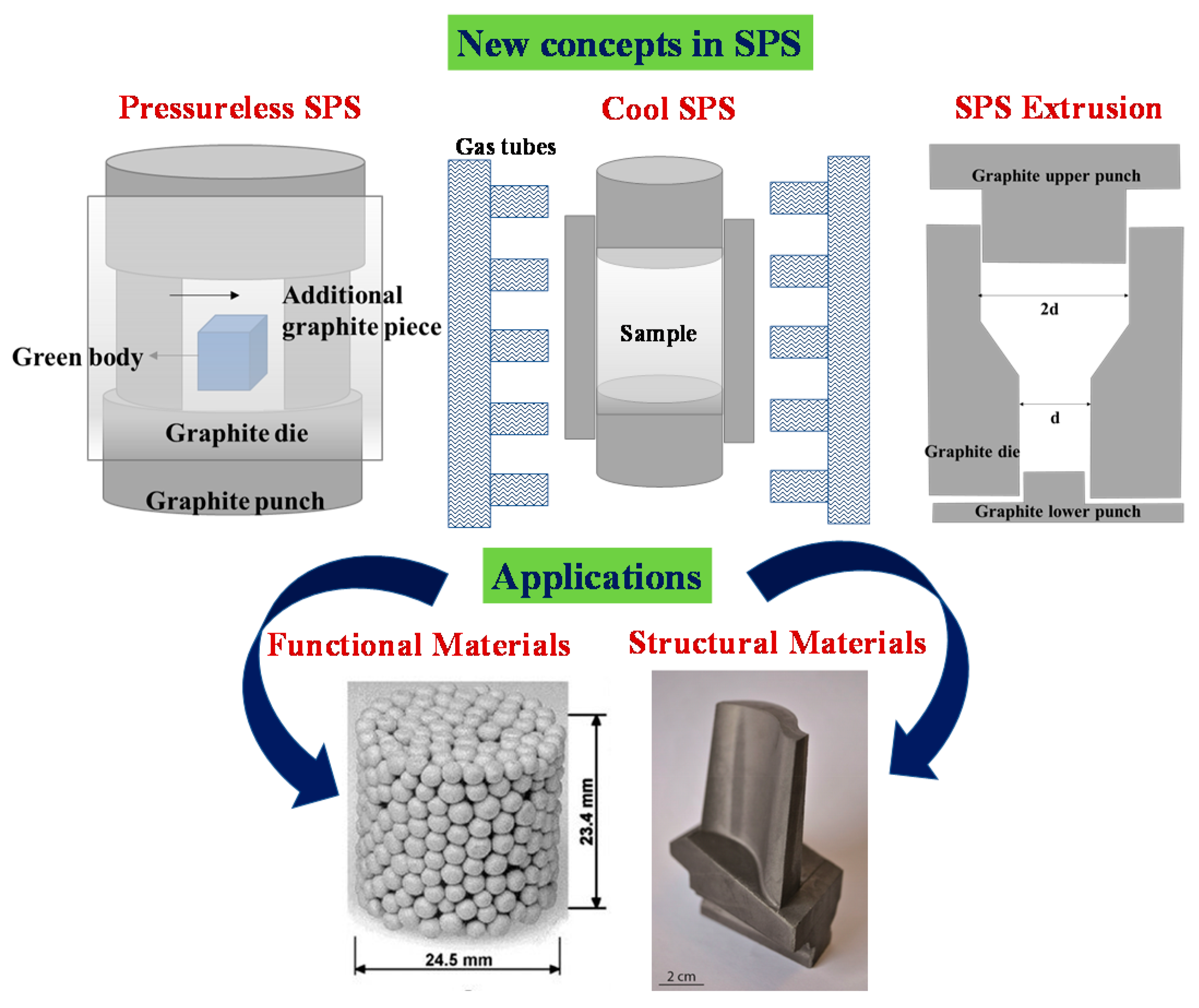
Figure 14.
Schematic illustrating various new advancements in the classical SPS technique for real-life industrial applications.
Figure 14.
Schematic illustrating various new advancements in the classical SPS technique for real-life industrial applications.

Publisher’s Note: MDPI stays neutral with regard to jurisdictional claims in published maps and institutional affiliations. |
© 2021 by the authors. Licensee MDPI, Basel, Switzerland. This article is an open access article distributed under the terms and conditions of the Creative Commons Attribution (CC BY) license (http://creativecommons.org/licenses/by/4.0/).
Share and Cite
MDPI and ACS Style
Nisar, A.; Zhang, C.; Boesl, B.; Agarwal, A. Unconventional Materials Processing Using Spark Plasma Sintering. Ceramics 2021, 4, 20-39. https://0-doi-org.brum.beds.ac.uk/10.3390/ceramics4010003
AMA Style
Nisar A, Zhang C, Boesl B, Agarwal A. Unconventional Materials Processing Using Spark Plasma Sintering. Ceramics. 2021; 4(1):20-39. https://0-doi-org.brum.beds.ac.uk/10.3390/ceramics4010003
Chicago/Turabian StyleNisar, Ambreen, Cheng Zhang, Benjamin Boesl, and Arvind Agarwal. 2021. "Unconventional Materials Processing Using Spark Plasma Sintering" Ceramics 4, no. 1: 20-39. https://0-doi-org.brum.beds.ac.uk/10.3390/ceramics4010003