1. Introduction
The last two decades witnessed the rapid advancement of digitization in dentistry. The advent of digital technologies like CAD/CAM systems and intraoral scanners has transformed the clinical, research, and production aspects of dentistry. CAD/CAM systems led to the introduction of novel restorative materials with improved esthetics and durability, increased automated production efficiency, and quality control of the prosthesis. Intraoral scanners have replaced traditional impressions with optical impressions [
1]. 3D modeling coupled with novel imaging modalities like cone beam CT, micro-CT, and MRI have unlocked novel diagnostic and dental treatment techniques as well as assessment techniques, such as digital smile designing [
2], virtual prosthetic-driven implant treatment planning and guided implant surgeries [
3,
4], anthroprometric and cephalometric analysis [
5], qualitative and quantitative analysis of endodontic procedures using 3D root canal models [
6], and finite element analysis [
7,
8,
9,
10].
Despite decades of high success rate in traditional metal-ceramic fixed partial denture (FPD), increased aesthetic demands coupled with the recent advancements in CAD/CAM technology have led to the emergence of all-ceramic FPD. Among all-ceramic materials, zirconia has gained immense popularity owing to this material’s excellent biocompatibility, dimensional stability, and superior mechanical performance. In comparison with other ceramics, densely sintered zirconia exhibited the highest stability as a framework material with an estimated five-year failure rate of 1.9% [
11]. Due to the lack of translucency, these zirconia frameworks are generally veneered with glass-ceramics to achieve a life-like appearance. Ironically, chipping of this veneering ceramic is reported to be the most frequent complication leading to overall prosthesis failure [
12,
13,
14]. Many retrospective clinical studies reported 1.9 to 30.2% of veneer chipping in zirconia-based prosthesis within three years of placement [
15,
16,
17,
18].
Currently, dental implants are widely used to restore functional occlusion in edentulous jaw regions. It has also been found that they have the potential to be used for critical patients under certain conditions to restore their dentition and improve their quality of life [
19]. The incidence of chipping in implant-supported FPDs is reported to be higher than the traditional tooth-supported FPDs [
20]. This could be attributed to the reduced proprioception as well as shock absorption capacity in implant-supported FPDs [
21]. Owing to the absence of a periodontal ligament and a dental pulp to control the chewing force, the masticatory loads on implant-supported prostheses are reported to be eight times higher compared to tooth-supported prostheses [
22]. Thus, understanding the mechanical behavior and ideal design parameters in all-ceramic implant-supported FPDs during function is necessary to reduce the risk of veneer chipping and to optimize the performance of prostheses.
Nevertheless, the functional stress distribution and biomechanical behavior of the framework and veneer layers within a prosthesis are difficult to study due to their complex geometry. This problem can be overcome by using 3D finite element analysis (FEA), which is a reasonably economical and efficient technique to investigate the failure behavior of complex structures such as dental prostheses [
8]. FEA structural analyses of a veneered zirconia fixed prosthesis assembly will help us to understand the interaction of various variables and offer valuable insight regarding the appropriate design parameters necessary to prevent higher stress patterns within the framework and veneering porcelain.
Clinically relevant anatomic 3D models simulating an implant-supported FPD assembly are rare as designing such models is time-consuming and laborious. Although there are a few studies on the FEA analysis of framework-veneer thickness in all-ceramic restorations, all of them were limited to either single crowns or the tooth-supported FPDs. To our knowledge, there is little information regarding the effect of veneer: framework thickness ratio on the stress distribution in a posterior implant-supported all-ceramic FPD cemented onto customized zirconia abutments, secured to their corresponding regular and wide diameter implant fixtures.
The objective of this study was to evaluate the effect of veneer: framework thickness ratio on the stress distribution and maximum principal stress values within a posterior bi-layered implant-supported all-ceramic FPD using 3D FEA. The null hypothesis was that there was no significant difference in stress distribution and maximum principal stress values with an altered veneer: framework thickness ratio.
2. Materials and Methods
2.1. Micro-CT Scanning
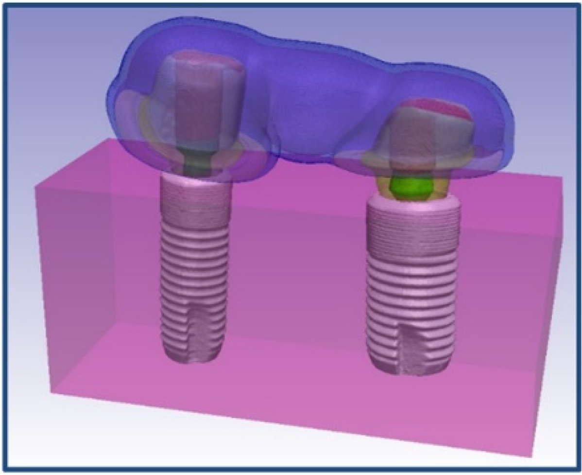
The implant-supported all-ceramic FPD model is an assembly comprised of two implant fixtures (Astra Tech OsseoSpeed, φ4.0 and φ4.8 mm; Dentsply Sirona, York, PA, USA), associated customized zirconia abutments, screws, cement layers, and an all-ceramic FPD are embedded within a bone (
Figure 1).
Two implant fixtures along with corresponding customized abutments and FPD were scanned using a micro-CT scanner with a 10 MP camera (Skyscan 1172, Microphotonics Inc.; Aartselaar, Belgium). The scanning parameters used were as follows: an accelerating voltage of 100 KV, current of 100 μA, exposure time of 1264 ms per frame, Al + Cu filter, and rotation step at 0.7°. The x-ray beam was projected in a direction parallel to the long axis of FPD as well as the implant fixtures with secured corresponding abutments. The image pixel size was 34.4 µm. The x-ray projections were reconstructed to form a 3D model, which was saved as a stack of BMP-type 3D files using NRecon software (Skyscan, Microphotonics Inc.; Aartselaar, Belgium). A beam hardening correction of 49% and ring artifact correction of 4 was used for the reconstruction. Cement layers and bone were created in Simpleware software (Synopsys Simpleware ScanIP Version P-2019.09; Mountain View, CA, USA) using segmentation tools.
2.2. Volume Mesh Generation
Stacks of the image slices generated using NRecon software were imported to an interactive medical image control system (Simpleware software) for further processing. Simpleware software organizes all the imported tomograph image slices and displays objects in three cross-sectional views (XY, YZ, and XY planes). The objects were then modified based on their threshold values and various other segmentation tools.
2.2.1. Implants
Masks of regular diameter implant fixture (OsseoSpeed, φ4.0 mm), as well as the associated abutments and screws, were obtained using thresholding based on image value, Boolean operations, morphological close, and recursive Gaussian filter tools. A similar procedure was followed for the wide diameter implant fixture (OsseoSpeed, φ4.8 mm), abutment, and screw to obtain their corresponding masks. 3D objects of regular and wide diameter implants with their corresponding screws and customized abutments were generated from created masks and converted to STL (Standard Tessellation Language or STereoLithography) files.
2.2.2. Fixed Dental Prosthesis
Masks with framework and veneer layers of 1 mm each were obtained using thresholding based on image value, Boolean operations, morphological close, and recursive Gaussian filter tools. Similarly, masks of 0.5 mm and 1.5 mm framework layers, and 0.5 mm and 1.5 mm veneer layers were obtained using Boolean operations. Cement layers were obtained by executing morphological dilate and Boolean operations on abutments. 3D objects were generated for all the created masks, and they were further converted into individual STL files.
2.2.3. Generation of Three Models and Volume Meshing
A cuboid surface object was created using “create object” tool. All the generated STL files of various objects such as implants, abutments, and FPD were then reimported. For the generation of the model, the STL files of different components were incorporated into a non-manifold assembly and altered simultaneously to ensure close approximation of various components within the assembly. Various models with different mesh densities were generated from this non-manifold assembly to do the convergence test.
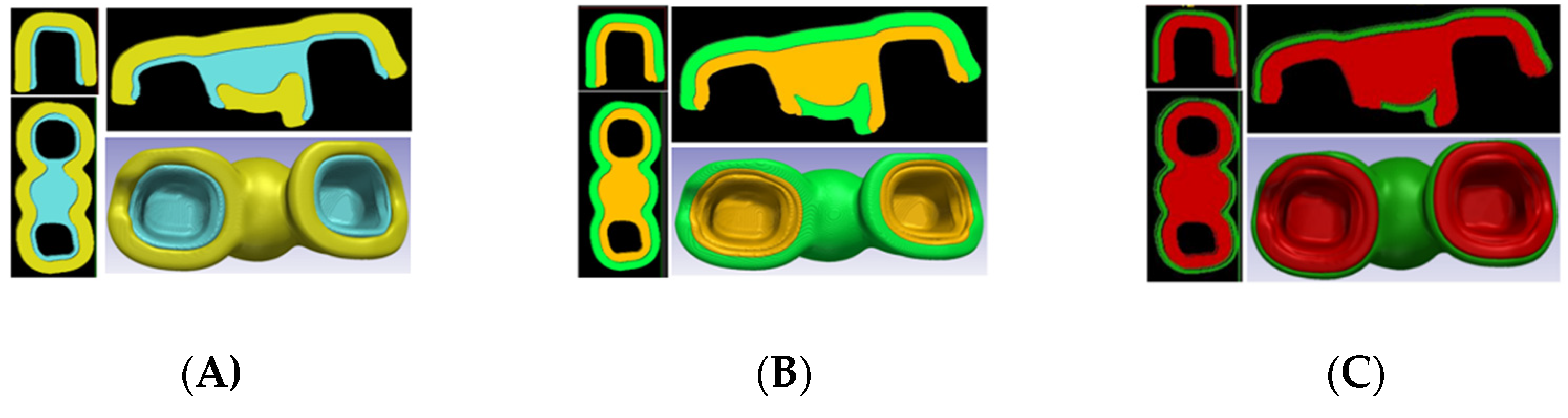
Using the appropriate mesh density value from the convergence test, three such models containing approximately 1,050,000 tetrahedral elements, with altered veneer: framework ratios (
Figure 2) were created. Model A (veneer: framework thickness of 3:1) consists of FPD with 1.5 mm veneer thickness and 0.5 mm framework thickness. Model B (veneer: framework thickness of 1:1) consists of FPD with 1.0 mm veneer thickness and 1.0 mm framework thickness. Model C (veneer: framework thickness of 1:3) consists of FPD with 0.5 mm veneer thickness and 1.5 mm framework thickness. The components of each model were meshed together using wrapping, smoothing operations, and a maximum geometric error of 0.05% to preserve the original geometry. The generated volume meshes were imported into the FEA software (ABAQUS FEA software; Dassault Systèmes Simulia Corp., Johnston, Rhode Island) for further analysis.
2.3. FEA Analysis
The following assumptions were made to simplify the FEA analysis: materials were considered to be isotropic and homogeneous with a linear elastic behavior throughout the entire deformation, “bonded type” contact was used and the bone/implant interface was assumed to be a perfect union so as to simulate complete osseointegration.
The material properties assigned to their respective components are tabulated in
Table 1 [
9]. The boundary condition was applied to all the superficial nodes (except occlusal/top surface) of the simulated cuboidal bone structure to prevent displacement in three spatial dimensions (no rotation/displacement allowed). An axial compressive load of 110 N was uniformly applied to 2300 nodes (0.048 N each) within the central occlusal fossa of abutments and pontic to simulate the physiological functional load on the FPD. The stress distribution values from the linear finite element analyses were evaluated according to the location and magnitude of the maximum first principal stress. Since all-ceramic materials primarily fail under brittle tensile fracture, the maximum principal stress values were taken into consideration for assessing stress distribution in this study.
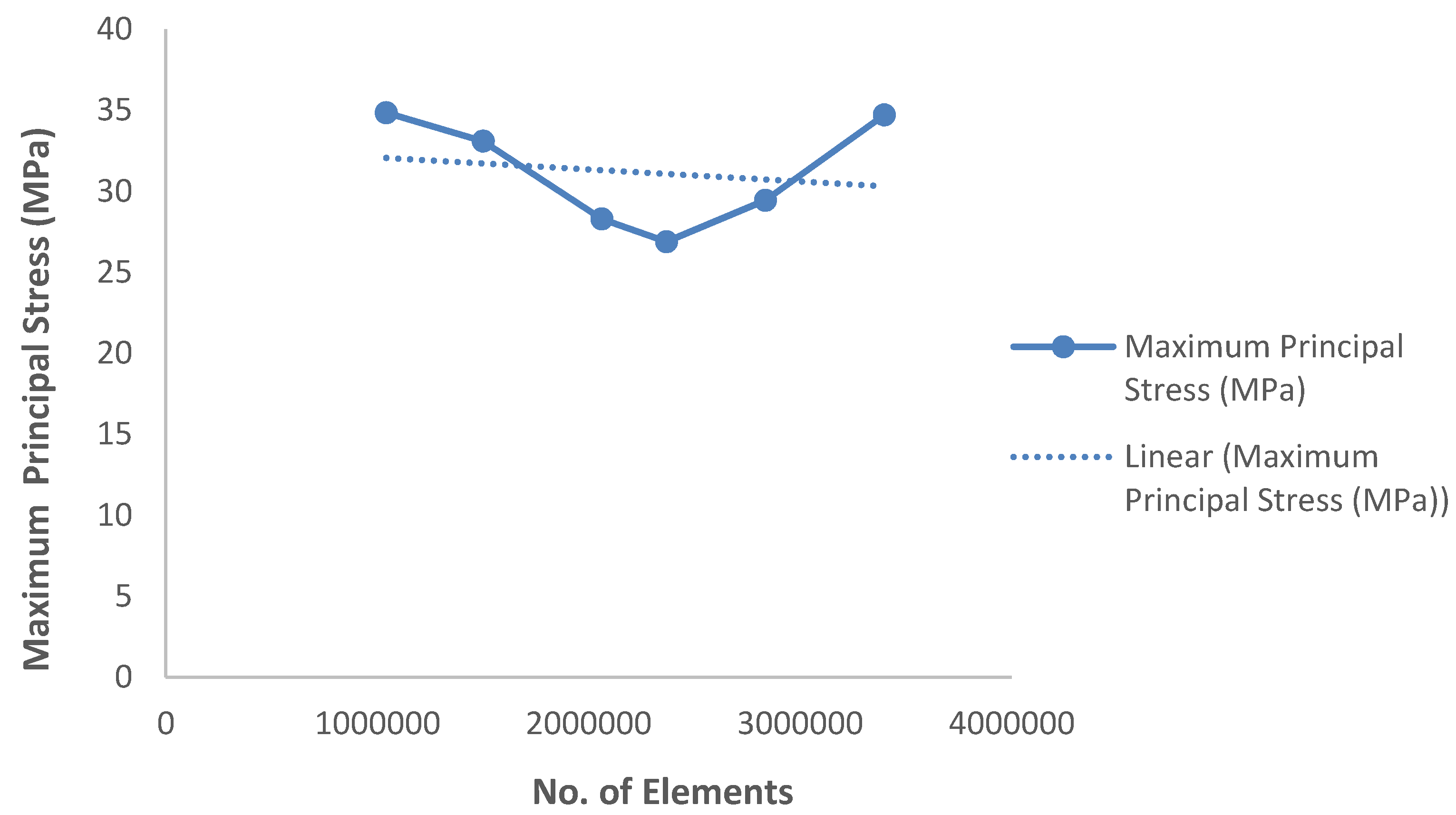
2.4. Convergence Test
The mesh quality, as determined by the number of elements, was controlled by adjusting the triangle edge length and the ratio between the height and base of the triangles. Using an iterative method, we increased the number of elements along each side and solved. We recorded the complexity of the model (no. of elements) vs. response (observed maximum principal stress value). The obtained maximum principal stress value calculated by varying the number of elements along each edge was plotted graphically. The solution point, wherein the response of the system converges to a solution and further mesh refinement (the addition of more elements) yields no significant response, was considered as the appropriate mesh density for carrying out FEA analysis.
3. Results
The 3D model showed great physical resemblance with the structure of an implant-supported FPD assembly. The use of non-manifold assembly ensured matching surfaces and coinciding nodes between different parts. The data from the convergence test, which was carried out to determine the appropriate mesh density for generating volume meshes, are plotted in
Scheme 1.
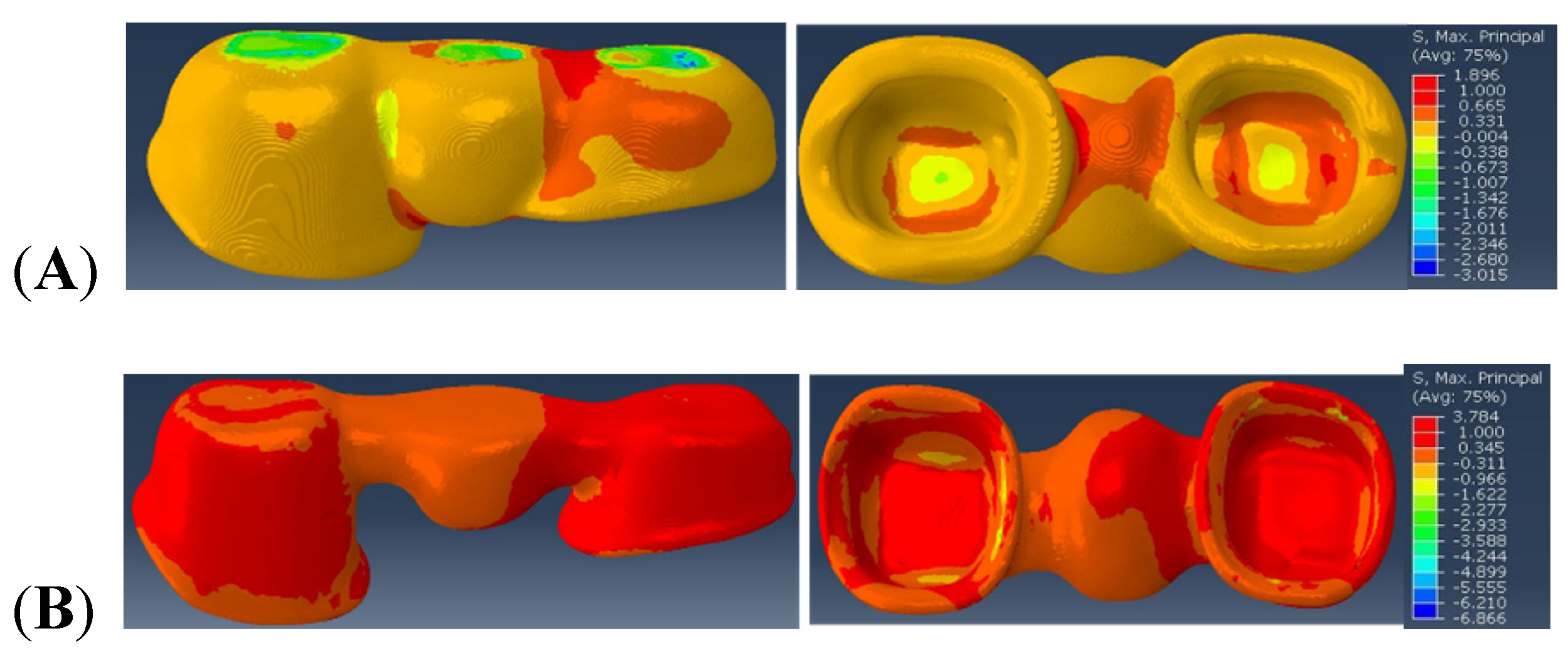
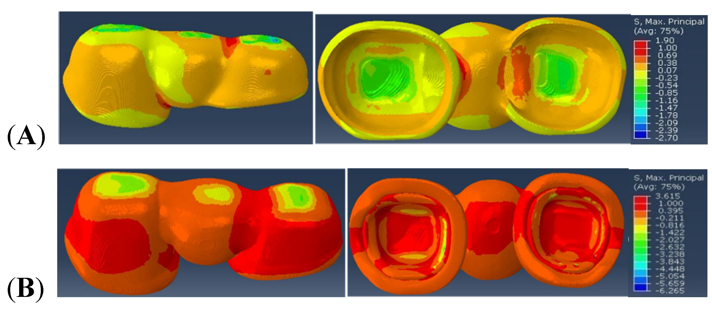
The stress distribution and maximum principal stress values observed within the veneer and framework regions of Model A (simulating the implant-supported FPD consisting of veneer: framework ratio of 3:1), Model B (simulating the implant-supported FPD consisting of veneer: framework ratio of 1:1), and Model C (simulating the implant-supported FPD consisting of veneer: framework ratio of 1:3) are depicted in
Figure 3,
Figure 4 and
Figure 5 respectively, with the red color representing high values, and blue color representing the lower values.
In Model A, the maximal principal stress value observed within the veneer in the distal connector region is 1.896 MPa and within the framework, the observed value is 3.784 MPa in the distal connector region and intaglio (cementation) surface of the retainers.
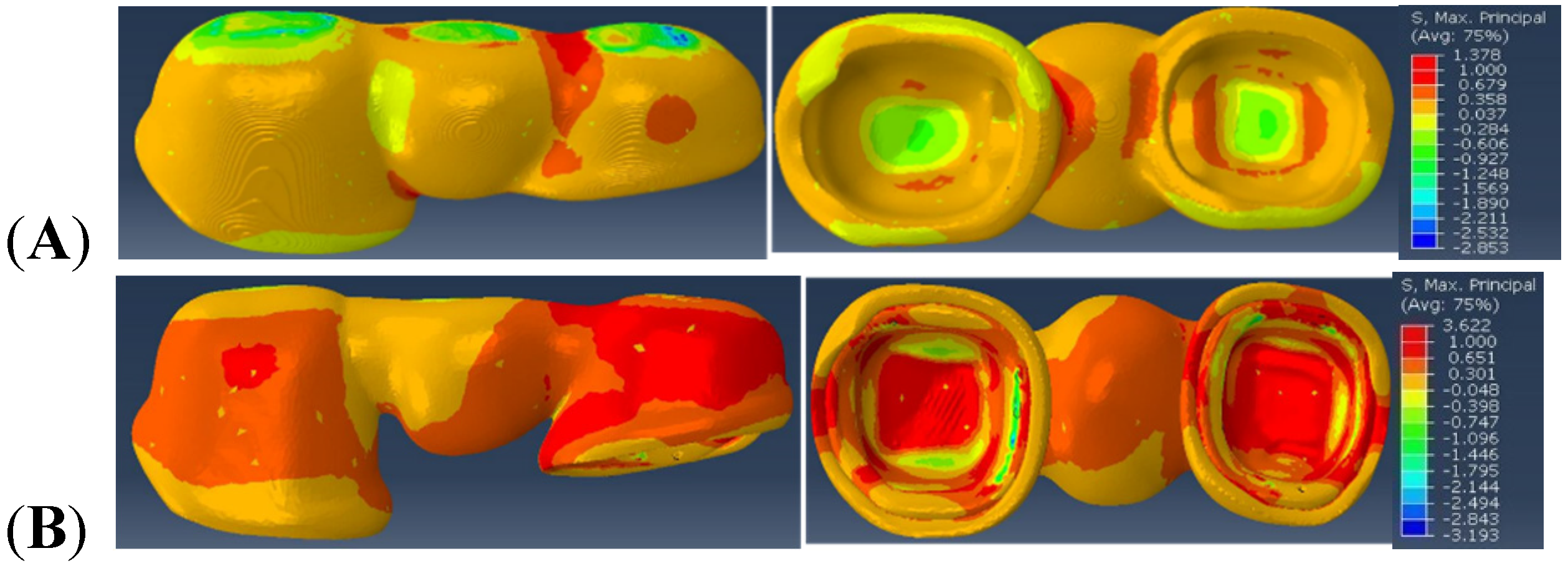
Similarly, the maximal principal stress value observed within Model B is 1.378 MPa in the distal connector region of the veneer. In the framework region of Model B, the maximum principal stress of 3.622 MPa is observed in the distal connector region and intaglio (cementation) surface of the retainers.
Furthermore, in Model C, the maximal principal stress value of 1.90 MPa is observed within the distal connector region of the veneer, and 3.615 MPa of maximal principal stress is observed in the distal connector region of the framework and in the intaglio (cementation) surface of the retainers, directly underneath the loading area.
4. Discussion
The stress distribution patterns and maximum principal stress values in the veneer and framework region varied with altered veneer: framework thickness ratios. Thus, the null hypothesis that veneer: framework thickness ratio would not affect the stress distribution and maximum principal stress values was rejected.
From the results, we can observe that the veneer and framework regions of Model B (veneer: framework thickness ratio of 1:1) depict the lower maximum principal stress values. This is in agreement with a parallel clinical study of 129 three-unit implant-supported FPDs. This study determined the mean survival time of the 1:1 veneer: framework thickness ratio was higher than the other two models. Although no significance was reached, a greater sample size could have yielded significant differences [
23]. This finding is also consistent with in vitro studies done by Soares LM et al. [
24], Nawafleh N. et al. [
25], in which, they observed higher fracture resistance values for tooth-supported all-ceramic FPDs with veneer: framework thickness ratios of 1:1.
Various in vivo and in vitro studies proposed that there are higher tensile stresses concentrated in the connector region and cervical area [
7,
10,
26,
27,
28,
29]. The reported results are in agreement with the results observed in this study, wherein the tensile stresses were concentrated in the distal connector region.
In this study, two different implant diameters (regular and wide diameter implants) were used to ideally simulate the clinical condition wherein the wide diameter implants were preferred in the posterior-most edentulous region and regular diameter implants around the first molar edentulous region. The variation in stress distribution patterns between two connector regions observed in all three models could be attributed to the difference in abutment dimensions of regular and wide diameter implants used in this study. The posterior-most connector region associated with wider diameter implant abutment demonstrated high tensile stress concentration in all three models.
This unique and translational study was performed in conjunction with an existing clinical study [
23,
30,
31] to corroborate results and elucidate predictability factors of FEA modeling in clinical scenarios. Although FEA is a theoretical, well-known, and widely used technique to assess the stress distribution among complex structures such as dental prostheses, there are certain limitations as there are several assumptions around which the models are created. The main limitations of this study revolve around these assumptions made during calculations such as the material properties, linear elastic behavior of the model, etc. These assumed values however do not ideally resemble living tissues. Moreover, in the oral environment, a humid atmosphere and the permanent occurrence of chewing forces might lead to the degradation of ceramics used for prosthetic restorations [
32,
33]. Furthermore, in this study, only axial loading condition was used to compare our models. Also, the FPD model used in this study is a simulated patient retrieved prosthesis and might vary slightly in dimensions and geometry from an ideal implant-supported FPD prosthesis. Thus, these inherent limitations in this study should be considered.
Apart from veneer: framework thickness, there are various other factors such as connector dimensions, radii of gingival curvature, framework design, loading conditions, FPD span, etc. that affect the stress distribution in implant-supported FPDs. Since posterior connector regions demonstrated higher tensile stresses in this study, altering the connector parameters such as connector height, radii of gingival curvature, etc. could be investigated to minimize the stress concentration in these regions. Further studies correlating various parameters is necessary to understand the mechanism of prosthesis failure in implant-supported FPDs in detail.
5. Conclusions
Within the limitations of this study, we can conclude that the framework bears the higher tensile loads. Furthermore, based on the results observed in this study, the veneer: framework thickness ratio of 1:1 results in a lower stress concentration than 1:3 or 3:1 veneer: framework thickness ratios. Also, the tensile stresses were concentrated in the posterior connector region of the prosthesis. Future studies correlating the connector dimensions and design are necessary to further evaluate the failure mechanism of implant-supported FPDs.
Author Contributions
Conceptualization, J.F.E.-U. and Y.D.; clinical relevance data acquisition, J.F.E.-U.; methodology, L.K. and M.S.; validation, Y.D.; formal analysis, L.K. and B.S.; investigation, L.K. and B.S.; resources, Y.D.; writing—original draft preparation, L.K.; writing— review and editing, B.S., Y.D., J.F.E.-U. and M.S.; visualization, L.K.; supervision, Y.D.; project administration, Y.D.; funding acquisition, J.F.E.-U. and Y.D. All authors have read and agreed to the published version of the manuscript.
Funding
This study was supported by NIH-NIDCR grant R01 DE025001 and the University of Florida Clinical and Translational Science Institute, which is supported in part by the NIH National Center for Advancing Translational Sciences under award number UL1TR001427. The content is solely the responsibility of the authors and does not necessarily represent the official views of the National Institutes of Health. Ceramic materials were provided by Ivoclar Vivadent and implant materials were provided by Dentsply. This study is registered in Clinical Trials. Gov under study number NCT01729858. The complete protocol can be viewed under this site.
Institutional Review Board Statement
Not applicable.
Informed Consent Statement
Not applicable.
Conflicts of Interest
The authors declare no conflict of interest.
References
- Davidowitz, G.; Kotick, P.G. The use of CAD/CAM in dentistry. Dent. Clin. N. Am. 2011, 55, 559–570. [Google Scholar] [CrossRef]
- Cattoni, F.; Teté, G.; Calloni, A.M.; Manazza, F.; Gastaldi, G.; Capparè, P. Milled versus moulded mock-ups based on the superimposition of 3D meshes from digital oral impressions: A comparative in vitro study in the aesthetic area. BMC Oral Health 2019, 19, 230. [Google Scholar] [CrossRef]
- Nikzad, S.; Azari, A.; Ghassemzadeh, A. Modified flapless dental implant surgery for planning treatment in a maxilla including sinus lift augmentation through use of virtual surgical planning and a 3-dimensional model. J. Oral Maxillofac. Surg. 2010, 68, 2291–2298. [Google Scholar] [CrossRef] [PubMed]
- Azari, A.; Nikzad, S. Flapless implant surgery: Review of the literature and report of 2 cases with computer-guided surgical approach. J. Oral Maxillofac. Surg. 2008, 66, 1015–1021. [Google Scholar] [CrossRef]
- Sakr, F.; Obaidy, K.; Assery, M.; Alsanea, J.; Nasser, A. Digitized dentistry: Technology that peaked up the professionality of dental practitioners. Saudi J. Oral Sci. 2017, 4, 3–11. [Google Scholar] [CrossRef]
- Sberna, M.T.; Rizzo, G.; Zacchi, E.; Capparè, P.; Rubinacci, A. A preliminary study of the use of peripheral quantitative computed tomography for investigating root canal anatomy. Int. Endod. J. 2009, 42, 66–75. [Google Scholar] [CrossRef]
- Augereau, D.; Pierrisnard, L.; Barquins, M. Relevance of the finite element method to optimize fixed partial denture design. Part I. Influence of the size of the connector on the magnitude of strain. Clin. Oral Investig. 1998, 2, 36–39. [Google Scholar] [CrossRef]
- Della Bona, A.; Borba, M.; Benetti, P.; Duan, Y.; Griggs, J.A. Three-dimensional finite element modelling of all-ceramic restorations based on micro-CT. J. Dent. 2013, 41, 412–419. [Google Scholar] [CrossRef] [PubMed] [Green Version]
- Fathy, S.M.; El-Anwar, M.I.; El-Fallal, A.A.; El-Negoly, S.A. Three-dimensional finite element analysis of lower molar tooth restored with fully milled and layered zirconia crowns. J. Dent. Health Oral. Disord. Ther. 2014, 1, 89–95. [Google Scholar] [CrossRef] [Green Version]
- Molin, M.K.; Onesti, M.P.; Petersson, T.B.; Derand, T.B. Three-dimensional finite element analyses of all-ceramic posterior fixed partial dentures with different designs. Int. J. Prosthodont. 2007, 20, 89–91. [Google Scholar] [PubMed]
- Pjetursson, B.E.; Sailer, I.; Makarov, N.A.; Zwahlen, M.; Thoma, D.S. All-ceramic or metal-ceramic tooth-supported fixed dental prostheses (FDPs)? A systematic review of the survival and complication rates. Part II: Multiple-unit FDPs. Dent. Mater. 2015, 31, 624–639. [Google Scholar] [CrossRef] [Green Version]
- Tanner, J.; Niemi, H.; Ojala, E.; Tolvanen, M.; Narhi, T.; Hjerppe, J. Zirconia single crowns and multiple-unit FDPs-An up to 8 -year retrospective clinical study. J. Dent. 2018, 79, 96–101. [Google Scholar] [CrossRef] [Green Version]
- Teichmann, M.; Wienert, A.L.; Ruckbeil, M.; Weber, V.; Wolfart, S.; Edelhoff, D. Ten-year survival and chipping rates and clinical quality grading of zirconia-based fixed dental prostheses. Clin. Oral Investig. 2018, 22, 2905–2915. [Google Scholar] [CrossRef]
- Miura, S.; Kasahara, S.; Yamauchi, S.; Okuyama, Y.; Izumida, A.; Aida, J.; Egusa, H. Clinical evaluation of zirconia-based all-ceramic single crowns: An up to 12-year retrospective cohort study. Clin. Oral Investig. 2018, 22, 697–706. [Google Scholar] [CrossRef] [PubMed]
- Gherlone, E.; Mandelli, F.; Cappare, P.; Pantaleo, G.; Traini, T.; Ferrini, F. A 3 years retrospective study of survival for zirconia-based single crowns fabricated from intraoral digital impressions. J. Dent. 2014, 42, 1151–1155. [Google Scholar] [CrossRef]
- Güncü, M.B.; Cakan, U.; Muhtarogullari, M.; Canay, S. Zirconia-based crowns up to 5 years in function: A retrospective clinical study and evaluation of prosthetic restorations and failures. Int. J. Prosthodont. 2015, 28, 152–157. [Google Scholar] [CrossRef] [PubMed]
- Monaco, C.; Caldari, M.; Scotti, R. Clinical evaluation of tooth-supported zirconia-based fixed dental prostheses: A retrospective cohort study from the AIOP clinical research group. Int. J. Prosthodont. 2015, 28, 236–238. [Google Scholar] [CrossRef] [Green Version]
- Christensen, R.P.; Ploeger, B.J. A clinical comparison of zirconia, metal and alumina fixed-prosthesis frameworks veneered with layered or pressed ceramic: A three-year report. J. Am. Dent. Assoc. 2010, 141, 1317–1329. [Google Scholar] [CrossRef]
- Gherlone, E.F.; Capparé, P.; Tecco, S.; Polizzi, E.; Pantaleo, G.; Gastaldi, G.; Grusovin, M.G. A Prospective Longitudinal Study on Implant Prosthetic Rehabilitation in Controlled HIV-Positive Patients with 1-Year Follow-Up: The Role of CD4+ Level, Smoking Habits, and Oral Hygiene. Clin. Implant Dent. Relat. Res. 2016, 18, 955–964. [Google Scholar] [CrossRef] [PubMed]
- Larsson, C.; Vult von Steyern, P. Five-year follow-up of implant-supported Y-TZP and ZTA fixed dental prostheses. A randomized, prospective clinical trial comparing two different material systems. Int. J. Prosthodont. 2010, 23, 555–561. [Google Scholar]
- Schulte, W. Implants and the periodontium. Int. Dent. J. 1995, 45, 16–26. [Google Scholar] [PubMed]
- Hammerle, C.H.; Wagner, D.; Bragger, U.; Lussi, A.; Karayiannis, A.; Joss, A.; Lang, N.P. Threshold of tactile sensitivity perceived with dental endosseous implants and natural teeth. Clin. Oral Implant. Res. 1995, 6, 83–90. [Google Scholar] [CrossRef]
- Esquivel-Upshaw, J.F.; Mecholsky, J.J.; Clark, A.E.; Jenkins, R.; Hsu, S.M.; Neal, D.; Ren, F. Factors influencing the survival of implant-supported ceramic-ceramic prostheses: A randomized, controlled clinical trial. J. Dent. X 2020, 3, 100017. [Google Scholar] [CrossRef]
- Soares, L.M.; Soares, C.; Miranda, M.E.; Basting, R.T. Influence of Core-Veneer Thickness Ratio on the Fracture Load and Failure Mode of Zirconia Crowns. J. Prosthodont. 2019, 28, 209–215. [Google Scholar] [CrossRef]
- Nawafleh, N.; Hatamleh, M.M.; Ochsner, A.; Mack, F. The Impact of Core/Veneer Thickness Ratio and Cyclic Loading on Fracture Resistance of Lithium Disilicate Crown. J. Prosthodont. 2018, 27, 75–82. [Google Scholar] [CrossRef]
- Rismanchian, M.; Shafiei, S.; Nourbakhshian, F.; Davoudi, A. Flexural strengths of implant-supported zirconia based bridges in posterior regions. J. Adv. Prosthodont. 2014, 6, 346–350. [Google Scholar] [CrossRef]
- Oh, W.S.; Anusavice, K.J. Effect of connector design on the fracture resistance of all-ceramic fixed partial dentures. J. Prosthet. Dent. 2002, 87, 536–542. [Google Scholar] [CrossRef] [PubMed]
- Salimi, H.; Mosharraf, R.; Savabi, O. Effect of framework design on fracture resistance of zirconium oxide posterior fixed partial dentures. Dent. Res. J. 2012, 9, 764–769. [Google Scholar]
- Correia, A.; Fernandes, J.; Campos, J.C.; Vaz, M.; Ramos, N.; Joao, M. Effect of connector design on the stress distribution of a cantilever fixed partial denture. J. Indian Prosthodont. Soc. 2009, 9. [Google Scholar] [CrossRef]
- Esquivel-Upshaw, J.F.; Clark, A.E.; Shuster, J.J.; Anusavice, K.J. Randomized clinical trial of implant-supported ceramic-ceramic and metal-ceramic fixed dental prostheses: Preliminary results. J. Prosthodont. 2014, 23, 73–82. [Google Scholar] [CrossRef] [Green Version]
- Esquivel-Upshaw, J.F.; Mehler, A.; Clark, A.E.; Neal, D.; Anusavice, K.J. Fracture analysis of randomized implant-supported fixed dental prostheses. J. Dent. 2014, 42, 1335–1342. [Google Scholar] [CrossRef] [PubMed] [Green Version]
- Swain, M.V. Impact of oral fluids on dental ceramics: What is the clinical relevance? Dent. Mater. 2014, 30, 33–42. [Google Scholar] [CrossRef] [PubMed]
- Joshi, G.V.; Duan, Y.; Della Bona, A.; Hill, T.J.; St John, K.; Griggs, J.A. Contributions of stress corrosion and cyclic fatigue to subcritical crack growth in a dental glass-ceramic. Dent. Mater. 2014, 30, 884–890. [Google Scholar] [CrossRef] [PubMed]
| Publisher’s Note: MDPI stays neutral with regard to jurisdictional claims in published maps and institutional affiliations. |
© 2021 by the authors. Licensee MDPI, Basel, Switzerland. This article is an open access article distributed under the terms and conditions of the Creative Commons Attribution (CC BY) license (https://creativecommons.org/licenses/by/4.0/).


 ,
, 


