Article

Wireless Volatile Organic Compound Detection for Restricted Internet of Things Environments Based on Cataluminescence Sensors

1
School of Information and Computer, Anhui Agricultural University, Hefei 230036, China
2
Anhui Province Key Laboratory of Pollutant Sensitive Materials and Environmental Remediation, Department of Materials Science and Engineering, Huaibei Normal University, Huaibei 235000, China
3
National Engineering Research Center for Agro-Ecological Big Data Analysis & Application, Anhui University, 111 Jiulong Road, Hefei 230601, China
*
Authors to whom correspondence should be addressed.
Submission received: 12 April 2022 / Revised: 2 May 2022 / Accepted: 3 May 2022 / Published: 9 May 2022
(This article belongs to the Special Issue Chemical Sensors for Volatile Organic Compound Detection)

Abstract

:
Cataluminescence-based sensors do not require external light sources and complex circuitry, which enables them to avoid light scattering with high sensitivity, selectivity, and widely linear range. In this study, a wireless sensor system based on hierarchical CuO microspheres assembled from nano-sheets was constructed for Volatile Organic Compound (VOC) online detection. Through sensor characteristics and data process analysis, the results showed that the luminous sensor system has good luminous characteristics, including the intensity of visible light, high signal/noise (S/N) values, and very short response and recovery times. Different VOC concentration values can be detected on multiple wavelength channels and different Cataluminescence signal spectra separations can process multiple sets of Cataluminescence data combinations concurrently. This study also briefly studied the mechanism action of the Cataluminescence sensor, which can specifically be used for VOC detecting.

1. Introduction

As the types of decorative materials in the human living environment increase, the pollutants in the air in trace amounts are gradually changing. The colorless irritating gas is difficult for ordinary people to detect and may be inhaled for a long time, which destroys the body’s hematopoietic function and appears to have central nervous system anesthetic effects, with severe cases even inducing lung cancer, leukemia, and other diseases. The United States Environmental Agency defines Volatile Organic Compounds (VOCs) as carbon-containing compounds other than carbon dioxide, carbonic acid, carbonates, metal carbides, and carbonaceous compounds that are involved in photocatalytic reactions in the atmosphere, including TVOC (Total Volatile Organic Compounds), aldehydes and benzene, toluene, xylene, etc. [1]. At present, although domestic and foreign researchers have established corresponding limit standards for aldehydes and benzene-based organic compounds, VOC substances detection with high sensitivity, low-cost, low-energy, fast, and reliable sensing methods has received continuous attention. The colorimetric method can only determine the total amount of organic volatile gases; gas chromatography has high separation efficiency, but the limitation of the boiling point of derivatives leads to low determination results; liquid chromatography is difficult for comparing the large number of interferences in VOC with the completely separated components; and the liquid chromatography-mass spectrometry instrument has a complex structure and high cost, making it difficult to use widely. Thus, it is important to study the VOC detection method with low cost, long life, and strong portability.
In the environment of an oxygen atom, the gas molecules can be used for heterogeneous catalytic oxidation on the surface of a solid catalyst. Therefore, catalytic light-emitting sensors have become one of the most effective methods for gas detection. Cataluminescence refers to the reaction of substances on the surface of catalytic materials to produce luminescence. Catalytic light-emitting sensors have received widespread attention due to their visible sensitivity, specific selectivity, and rapid response [2,3,4,5,6]. Cataluminescence sensors consume only oxygen and sample molecules in the air during the luminescence process, while the fixed solid catalyst is nearly not consumed. Therefore, the gas sensor using nanomaterial as a sensitive material overcomes the shortcomings of traditional sensor reagent consumption and shedding and is expected to develop into a new class of practical chemiluminescent gas sensors [7,8,9]. In the past few years, people have developed CTL sensors with excellent performance, excellent selectivity, and fast response and recovery [10,11,12,13]. Zhang Runkun and coworkers developed a gas sensor system for the detection of luminescence (CTL) emissions of hexafluoride groups by using a Zn-doped SnO2 composite. The results show that the linear detection range of the sensor system is lower than the standard detection concentration and the pattern recognition method can be used to detect the identifiability of the sensor [14]. Based on the Cataluminescence (CTL) emission of MgO/In2O3 composite (with a mass ratio of 1:2), Liu developed a gas sensor for the determination of dimethyl ether and isopropanol. The sensor has high sensitivity and selectivity to analyte at 245 °C [15].
High sensitivity, good selectivity, and fast response contribute to the interest in Cataluminescence and also provide significant challenges to achieving significant enhancements in Cataluminescence-based sensor systems. However, in the process of routine analysis and application of chemiluminescence sensors, there are still some deficiencies found. These are mainly due to the short life of the sensor and the signal drift caused by the consumption of luminescent reactants, which limits the application of the chemiluminescence sensor in practical analysis [16]. For this reason, it is urgent to manufacture a chemiluminescent sensor with high sensitivity and stability, a simple preparation process, and a long service life. The continuous development of nanotechnology has provided new opportunities for the research of chemiluminescence sensors [17]. Some gases can produce strong chemiluminescence on the surface of specific nano-materials, so nano-materials can be used to design different types of Cataluminescence sensors for sensitive materials [18]. Moreover, with the development of wireless communication technologies, a lot of sensor systems have been developed for use in remote monitoring and control applications consisting of environmental, wildlife monitoring, road tunnel monitoring, building structural health monitoring, and gas leakage and detection. Wireless communications have many advantages, including remote monitoring, low cost, fast response, self-organizing, and flexible layout, while reports of their application in analytical smart CTL sensors that detect and identify multiple hazardous vapors in real time are rare. As mentioned above, a wireless CTL sensor system is needed for harmful gas monitoring which has a wireless communication technology function. For the determination of benzene and toluene gas, Wang Jian and his colleagues have raised a sensitive CTL sensor. However, while the method is successful to steam detection, it also has short board in remote control and the transfer of data [19].
Some nano-oxides and metal or noble-doped nanomaterials have better chemiluminescence signals and can be used to construct Cataluminescence sensing materials. However, most of them require noble metal or metal doping which is costly and complicated to synthesize. CuO is a p-type metal oxide with good characteristics like no toxicity, availability, and a smaller band gap (1.3–2.4 eV). The combination of CuO and other metal oxides will produce unique p-n hybrid materials which show the quality of high-efficiency photocatalytic materials [20]. In this study, nano-oxide CuO with low cost and abundant sources was selected as the catalytic material, the preparation method was simple, and the cost was low.
Specifically, the technical contributions of this paper are the following: In this study, the Cataluminescence sensor system was used as a practical tool for detecting harmful gases. A theory of dynamic and static characteristics of gas sensors was introduced and a wireless sensor system based on hierarchical CuO microspheres assembled from nano-sheets was constructed in Section 2. The third section introduces the theoretical derivation of the system and discusses the experimental results and analysis in detail. Finally, Section 4 summarizes the whole paper.

2. Experiments and Methods

2.1. Experiment Reagents

In this study, we used a reagent of a high-purity (98.5%), analytical-grade sample, and did not further purify it for experimental use.

2.2. Preparation of the Sensor Material

A simple chemical solution method was used to prepare hierarchical CuO microspheres assembled from nano-sheets, that is, 2.4 mmol of Cu(CH3COO)2·H2O was completely dissolved in 60 mL of deionized aqueous solution. Then 4 mL of ammonia (25–28%) was added to the above mixture and stirred slowly until a clear solution was formed. The solution was sealed in a conical flask with a cover and heated at 82 °C for 150 min. Then it was naturally cooled to room temperature to obtain a synthetic black powder which was washed several times with anhydrous alcohol and deionized water before finally being dried in the oven for more than 12 h [21]. We prepared hierarchical CuO microspheres assembled from nano-sheets by this simple chemical solution method.

2.3. Preparation of Test Gas

The method for preparing a certain concentration of the gas sample was as follows: a micro-sampler drew a certain amount of the sample solution to be tested (analytically pure liquid reagent) into a fixed volume flask and sealed the flask with a rubber stopper. The relationship between the mass of the reagent added to the flask and the volume of the flask after the liquid sample was completely volatilized. The sample to be tested was converted into the corresponding gas density (ppm) at normal temperature and pressure and the gas concentration was calculated as follows:
C = 22.4 V a × d V f × M
where 24.5 is the molar volume of the gas (L/mol), Va represents the volume (μL) of the liquid injected into the flask, Vf represents the volume of the flask (m3), d represents the density of the liquid (mg/µL); M represents the molecular weight of the liquid substance [22].

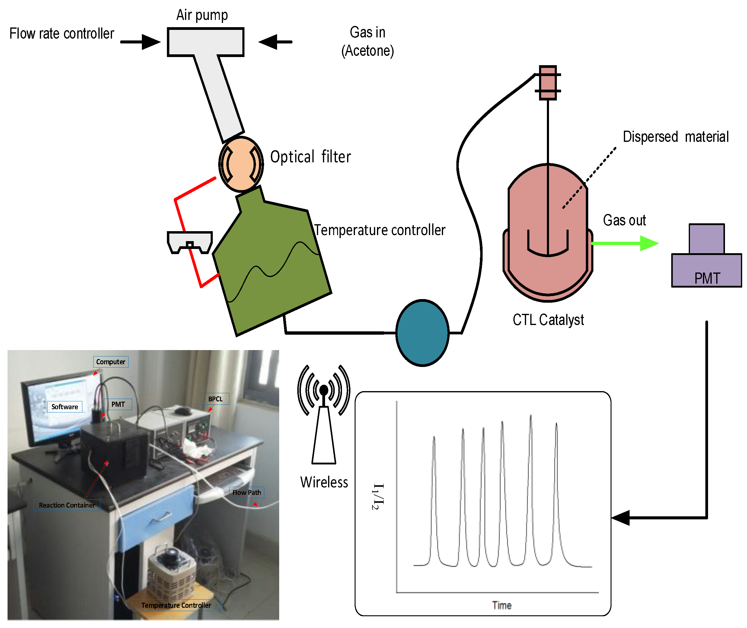
2.4. Experiment Instruments

The product was characterized by an X-ray diffractometer (XRD), field emission scanning electron microscope (FESEM, quanta200feg), and transmission electron microscope (TEM, JEOL JEM-2100). Micromeritics ASAP 2020 M + C Brunauer-Emmet-Teller (BET) equipment was used to test the specific surface area of the sample (4.84 m2/g) and N2 gas was used as the carrier gas.
The system diagram of the wireless luminous sensor is shown in Figure 1. Dispersed material was placed on a CTL catalyst with an inner diameter of approximately 10 mm. The dispersed material was a thickness of 0.5 mm. The air pump could control the gas flow and quickly disperse the test gas. The sensor is equipped with an optical filter and the working temperature can be adapted by adjusting the temperature controller. Catalysis occurred on the surface of the catalytic material as it flowed through the CTL catalyst part. The wireless ultra-weak chemiluminescence sensor system collected the luminous intensity of the photomultiplier tube (PMT) and we chose to use the optical filter in the range of 400–650 nm to test the wavelength.
The wireless harmful gas online detection system is an interactive system integrating Internet of Things sensor technology. It operates based on a data acquisition module, a data transmission module, and a remote monitoring platform. The data acquisition module consisted of phase modulation, analog modulation, amplitude modulation, and frequency modulation, where the cloud service platform was divided into wireless transmission module data collection and telecommunication module. A general schematic diagram of wireless CTL harmful gas online-detection system is shown in Figure 2.

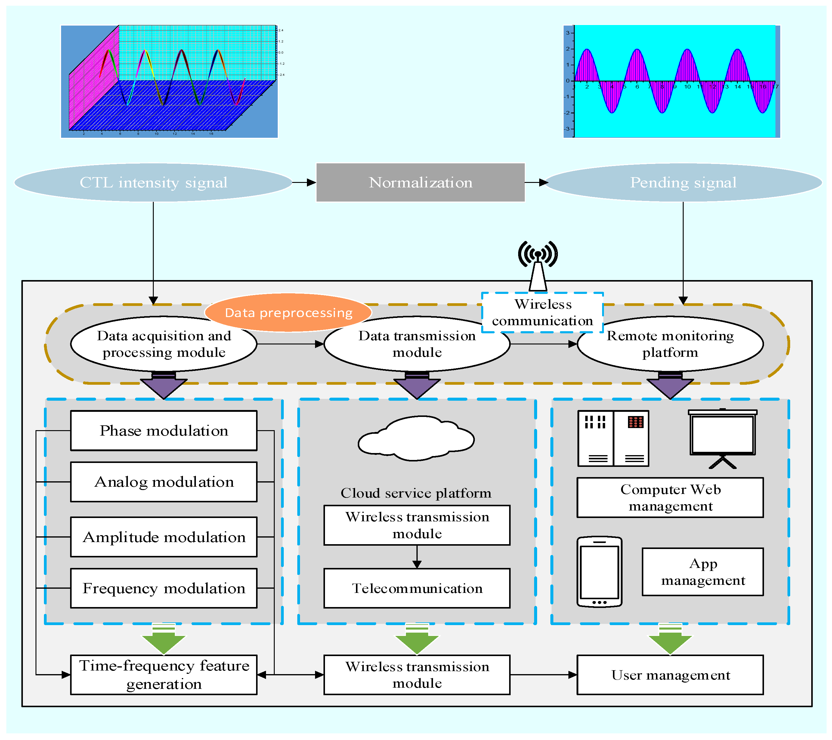
2.5. Theory of Sensor Characteristics and Data Process

A layer of catalytic material was coated onto the ceramic heating core and its thickness was controlled to be about 0.4 mm. After being naturally dried, it was placed in a quartz tube with a gas inlet and an outlet at the wall (Φ = 14 mm). When an experimental device was connecting, the temperature of the heating core was controlled through a voltage regulator and the temperature of the catalyst on the heating core was measured by a thermocouple. The gas flow meter was used to adjust the air flow rate through the tube made of quartz. The gas to be tested was carried by pure air and flowed through the quartz tube and a catalytic oxidation reaction occurred on the catalyst to release the photons. The photons passed through the filter below and were amplified by a photomultiplier tube and detected by the luminescence system [23].
In this study, the calculation process of relative Cataluminescence intensity was as follows:
S = S max × N
where Smax was the peak response of Cataluminescence, N was the background average value of the measurements. The detection limit of the sensor was calculated as follows:
L O D = 3 σ / k
where σ was the blank standard deviation and k was the slope of the working curve. The static characteristic Equation (4) was used to describe and express the relationship between the output of the detection system and input of which
y ( x ) = a 0 + a 1 x + a 2 x 2 + + a i x i + + a n x n
where x was the input quantity; y(x) was the output; and a0, a1, a2, …, ai, …, an was a constant coefficient term. For the linear time invariant CTL detection system, the constant coefficient linear differential equation characterizing its dynamic characteristics was:
a n d n Y t d t n + a n 1 d n 1 Y t d t n 1 + + a 1 d Y t d t + a 0 Y t = b m d m X t d t m + b m 1 d m 1 X t d t m 1 + + b 1 d X t d t + b 0 X t
when initial t = 0, the initial conditions that output y(t) = 0 and input X(t) = 0, and the initial values of their derivatives to time were all zero, then the transfer Function (6) of CTL measurement system was:
H s = Y s X s = b m s m + b m 1 s m 1 + + b 1 s + b 0 a n s n + a n 1 s n 1 + + a 1 s + a 0
Expression of amplitude and the phase frequency characteristic:
A ω = H j ω = K 1 ω ω 0 2 2 + 2 ζ ω ω 0 2
φ ω = arctan 2 ζ ω ω 0 1 ω ω 0 2

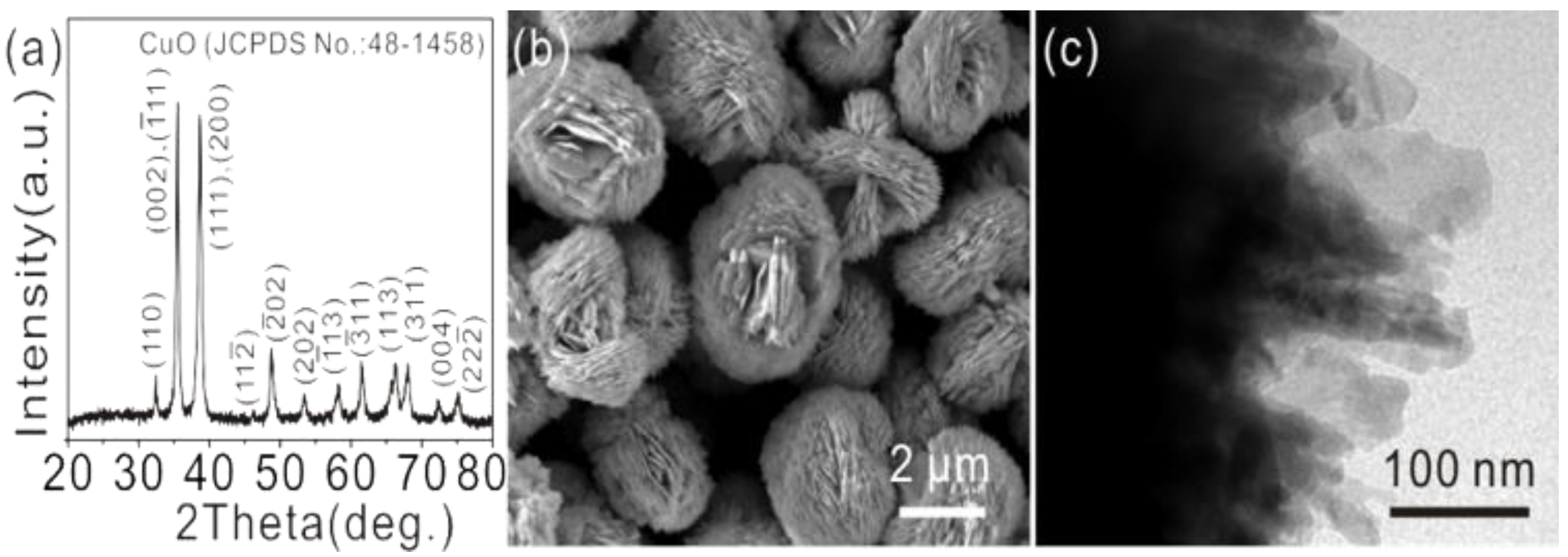
2.6. Characterization of Sensor Material

Figure 3a shows the product’s X-ray diffraction (XRD) pattern. All the sharp diffraction peaks of the product can be labeled as the monoclinic CuO (JCPDS No.: 48-1548). SEM (Scanning Electron Microscopy, Figure 3b) and TEM (Transmission Electron Microscopy, Figure 3c) images showed that the structures of the hierarchical CuO microspheres were constituted with nano sheets. The O2− ions were successfully doped into the CuO lattice and compared to pure Cu nano-materials. For CuO, the use of reflectance spectra in UV showed an extension of the absorption edge to the visible region, which can be attributed to the Cu2+ dopants.
The Cu2p XPS spectrum of CuO microspheres assembled with nano-sheets is shown in Figure 4. Figure 4 shows the Cu2p XPS spectrum of CuO microspheres assembled with nano-sheets. For the Cu2p spectrum, the peaks corresponded to the 2p3/2 and 2p1/2 transitions of copper at 932.3 and 952.2 eV, respectively. Meanwhile, satellites on the higher binding energy sides were also visible (indicated by *). These values were comparable to the values reported for the Cu2p levels (Cu2+) species in CuO [24,25]. In this study, the hierarchical CuO microspheres were synthesized and the strength of CTL effects on VOCs was investigated.

3. Luminescence Detection Analysis

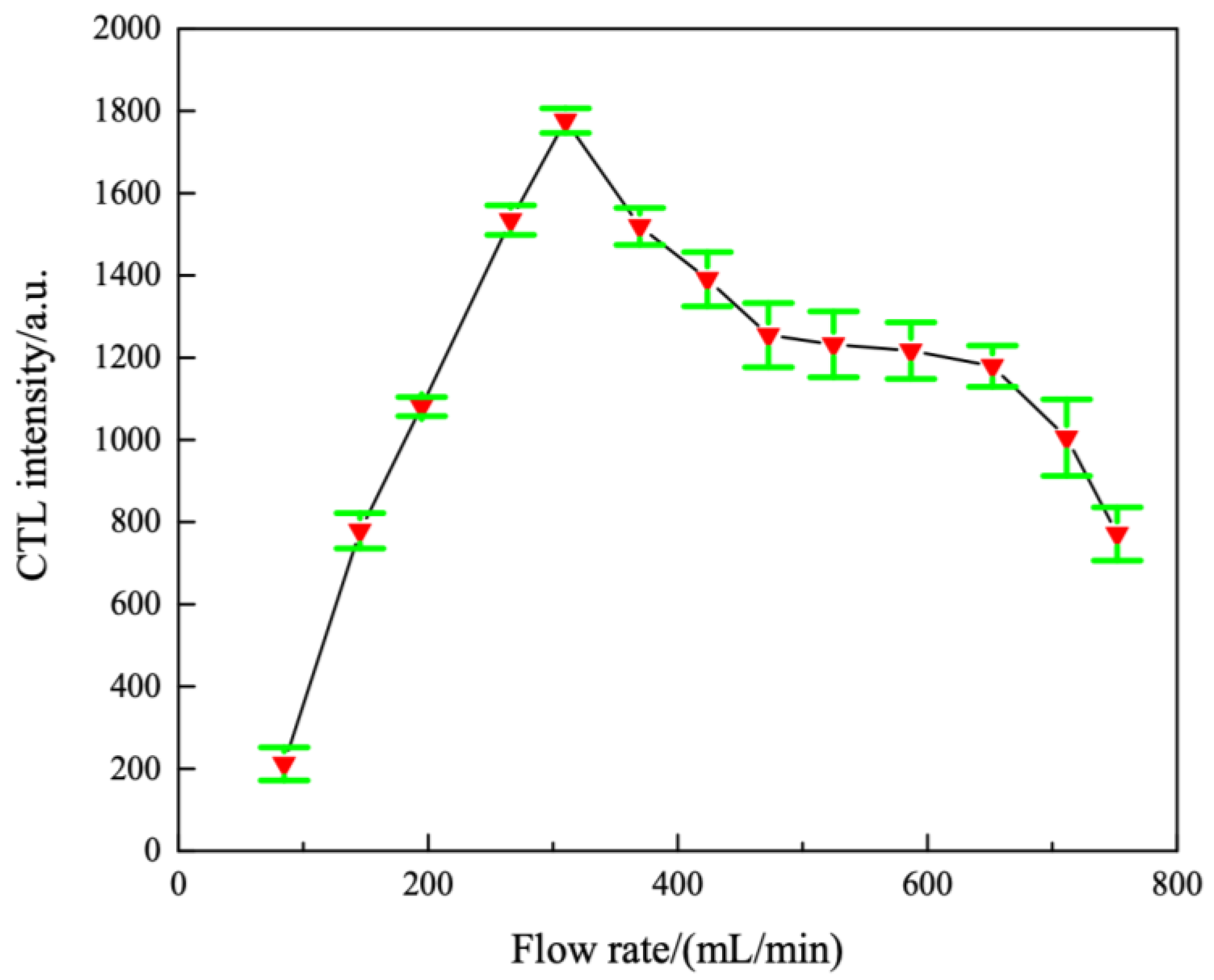
3.1. Optimization of Air Flow Rate

The experimental temperature was adjusted to 220 °C and 200 ppm acetone vapor was injected at a wavelength of 425 nm. The relationship between the flow rate of the carrier gas and the acetone luminescence intensity was measured. As shown in Figure 5, when the flow rate of the carrier gas was between 50 and 310 mL/min, the CTL intensity increased with the increase in the carrier gas flow rate. When the flow rate of the carrier gas was greater than 310 mL/min, the CTL intensity decreased with the increase in the carrier gas flow rate. This indicated that at lower flow rates, the diffusion rate of oxygen molecules may be lower than that of acetone, thus the luminescence intensity increased with the flow rate. The condition of the constant reaction rate was that the flow rate of the carrier gas was more than 310 mL/min. The flow rate was too large and the acetone molecules were not sufficiently reacted on the sensitive material to be lost, so the luminescence intensity decreased as the flow rate increased at a higher flow rate. Therefore, this study determined 310 mL/min to be the optimum carrier gas flow rate.

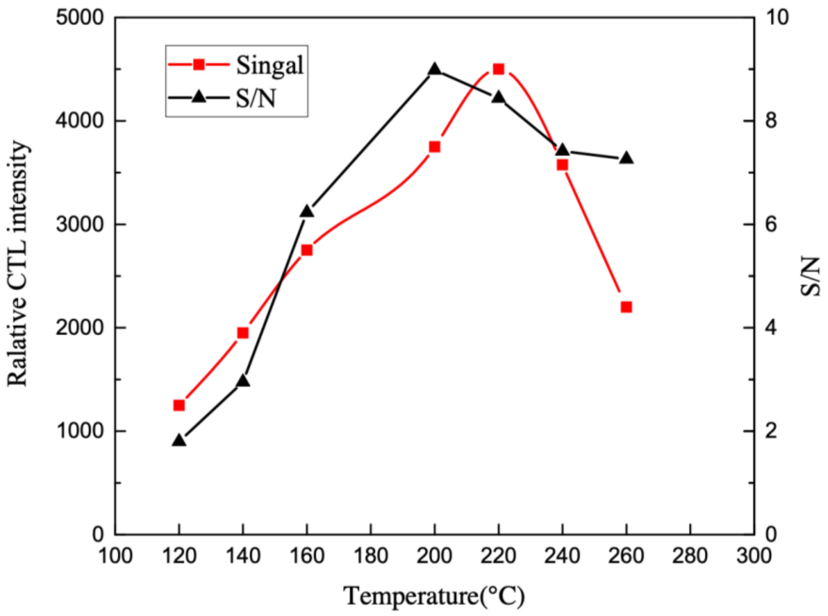
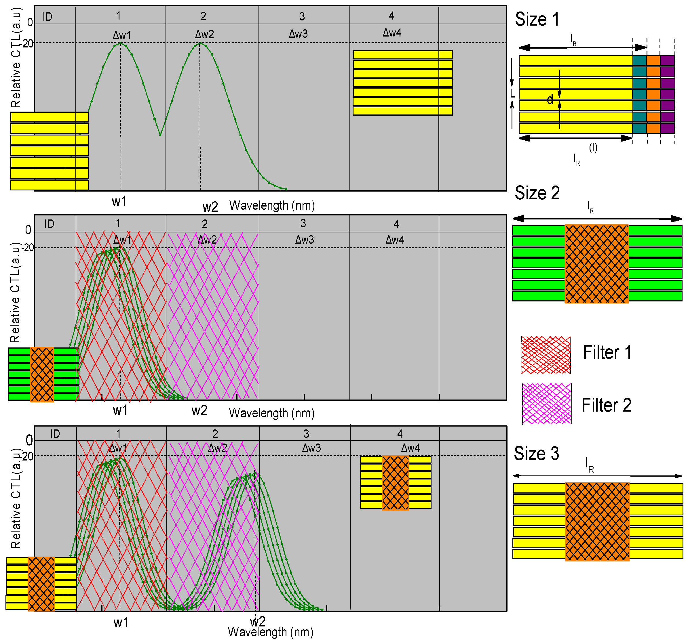
3.2. Optimal Wavelength and Temperature Selection

The catalytic emission wavelength of acetone on the surface of the test CuO material was first tested by using an optical filter from 400 to 630 nm (400, 420, 480, 530, 560, 590, 630). Figure 6 shows the change in the Cataluminescence intensity of acetone at different wavelengths with a temperature of 220 °C and a flow rate of 310 mL/min. Since the incandescent lamp from the ceramic heater emits longer wavelength radiation, the noise signal (S/N) will increase. Thus, the S/N ratio was used to display the actual illumination intensity. The calculation method of the signal-to-noise ratio is 10 lg (PS/PN), where PS and PN represent the effective power of the signal and noise, respectively, and can also be converted into the ratio relationship of voltage amplitude: 10 lg (VS2/VN2), where VS and VN represent the effective value of the signal and noise voltage, respectively. As shown in Figure 6, acetone has a maximum emission wavelength of 590 nm and a maximum signal-to-noise ratio (S/N). As a consequence, the best test wavelength of the CuO luminescence sensor is 590 nm. At the same time, it can be seen from Figure 6 that the Cataluminescence signal is the strongest at 590 nm and the curve shows its characteristic spectral shape. This may be due to the energy difference of the high energy state luminescent intermediates produced in the Cataluminescence reaction. This difference varies from substance to material and was therefore of great importance for substance identification and selective detection.
This study used filters to separate each group of test CTL signal spectra. Different CTL signal spectra separations can process multiple sets of CTL data combinations concurrently (Figure 7). The CTL signal spectra change in the channels with the center wavelengths of w1, w2, w3, and w4, and will not interact with each other. During our experiment, center wavelengths were selected from 400 to 630 nm (400, 420, 480, 530, 560, 590, 630). If the sensing wavelengths are sufficiently separated, wavelength separation can be used in the frequency domain or gating in the time domain to discern the evolution of each catalytic luminescence feature in the central channel wavelength. For example, in the vicinity of the central wavelengths w1, w2, w3 and w4, these four groups of wavelengths are independent and do not interfere with each other, so different relative catalytic luminescence values can be detected on the different channels. Different relative acetone concentration values can be detected on multiple wavelength channels. Based on the principle of anti-collision technology in spectral separation, multiple pieces of CTL spectral information can be processed at one time. The filters are independent and will not interfere with each other, so different relative CTL values can be detected in multiple channels.
The impact of operating temperature on luminescence sensor systems has remained a serious issue. In this research, the influence of reaction temperature on luminescence intensity was studied. Figure 8 shown that, as the test temperature increased, the luminescence intensity of acetone also increased. This was due to the fact that at high temperatures, O atoms were doped into the layered CuO microsphere composite assembled from nano-sheets and the conversion of acetone was higher. However, due to the increase in noise, the signal-to-noise ratio decreases significantly at about 220 °C. Given to these results, we chose 220 °C as the test temperature for further study.

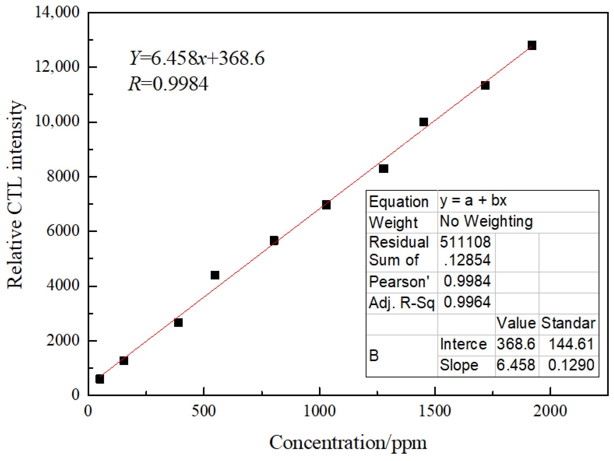
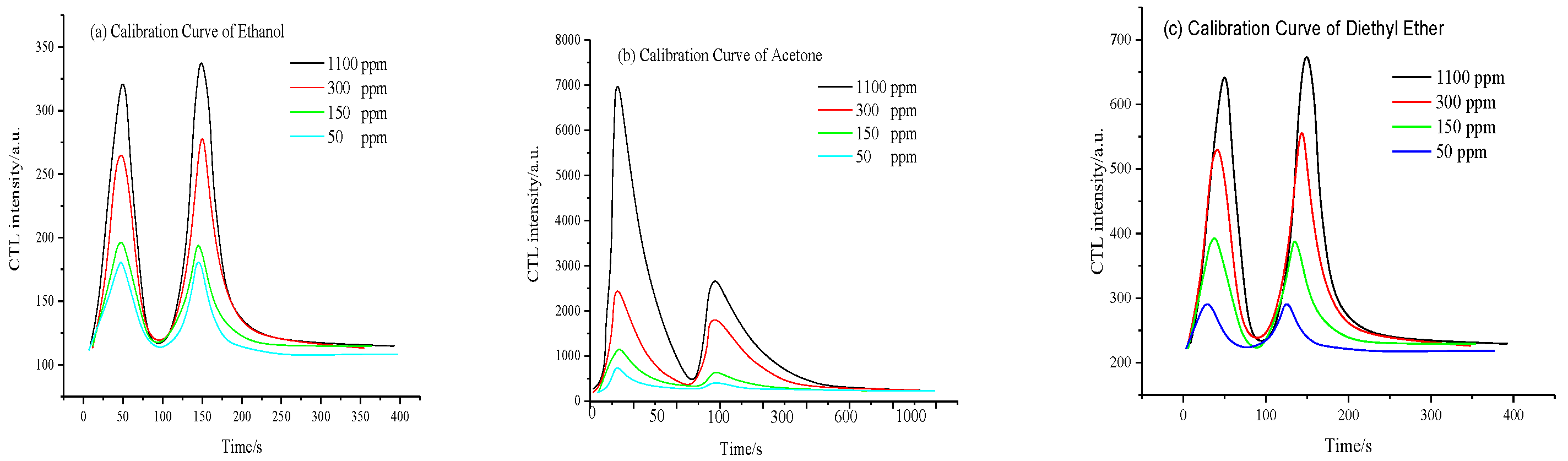
3.3. Linearity Characteristics

In conclusion, under the best experimental conditions, this study investigated the relationship between the concentration platform of acetone and luminescence intensity. The results showed that there was a good linear relationship with luminescence intensity in the range of 15.0~2200.0 ppm, the correlation coefficient was r = 0.9991, and the detection limit was 1.65 ppm (Figure 9). Referring to the detection limit of 1.65 ppm, the sensitivity of the sensor can meet the detection requirements of acetone. The relative standard deviation of the six-time luminescence intensity measured in parallel for 100 ppm acetone gas was 1.9%. The detection performance of the method was comparable to that reported in the literature [26] and has a wider linear range. In addition, the detection method did not require pre-processing and the response speed was fast.

3.4. Linearity Characteristics

For the same catalyst, when the reactants are different, the catalytic effect it exhibits may vary widely. In order to verify the selectivity of nano-catalysts for the catalytic oxidation of acetone, this study investigated the responses of ethanol, dimethyl ether, n-butanol, propanol, and other gases that may interfere with the detection of acetone by this sensor. Under the optimal detection conditions of 590 nm, 210 °C, and 310 mL/min, different concentrations of ethanol, dimethyl ether, n-butanol, and propanol vapor were loaded into the reaction chamber through the air. The output signal represented the production of a response signal index, as the heating rod itself had the cataluminescence response for the test gas, which contained the output signal of the heating rod polished with catalytic material and the output signal of the clean heating rod. The output signal, which produced a response signal with specific combinations of catalytic materials at different concentrations of ethanol (a) and acetone (b) vapors, is shown in Figure 10.
It can be concluded that the first-order CTL phenomenon due to the different alcohol molecules is derived from the catalytic oxidation of gas molecules to produce a first-order product. The generation of secondary CTL may result from the catalytic oxidation of the primary product to the secondary product. The remaining sample molecules are catalytically oxidized. Due to the different molecular structures of the different alcohols, the products produced by the stepwise CTL reaction are different. The adsorption performance, reactivity, and reaction rates of these products on the catalytic materials are different. Therefore, the luminescence intensity produced by the CTL reactions at different levels was also different, resulting in different I1/I2 values of different alcohol vapors on the same catalytic material combination. Since the luminous efficiency, reaction rate, and conversion rate of the same alcohol molecule on different catalytic materials are different, the I1/I2 values of the same alcohol vapors in different catalytic material combinations are also different. Therefore, based on the I1/I2 eigenvalues, it is possible to identify alcohol vapors with similar properties [27]. It is worth noting that the various alcohol vapors were in the range of experimentally selected concentrations (50 to 1000 ppm) and the I1/I2 values remained unchanged, which is very advantageous for practical applications of the CTL sensor. The interference of ethyl ether and ethanol on acetone was 7.5% and 4.2%; other gases do not interfere with the determination.

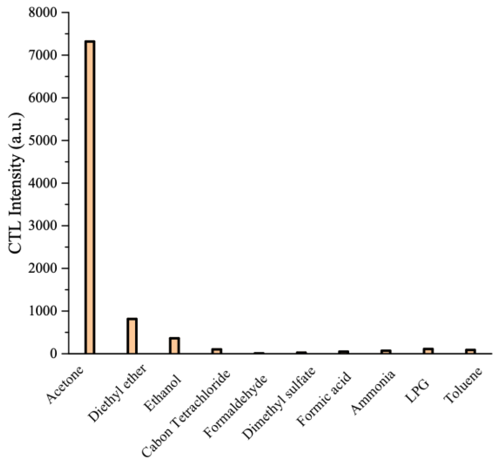
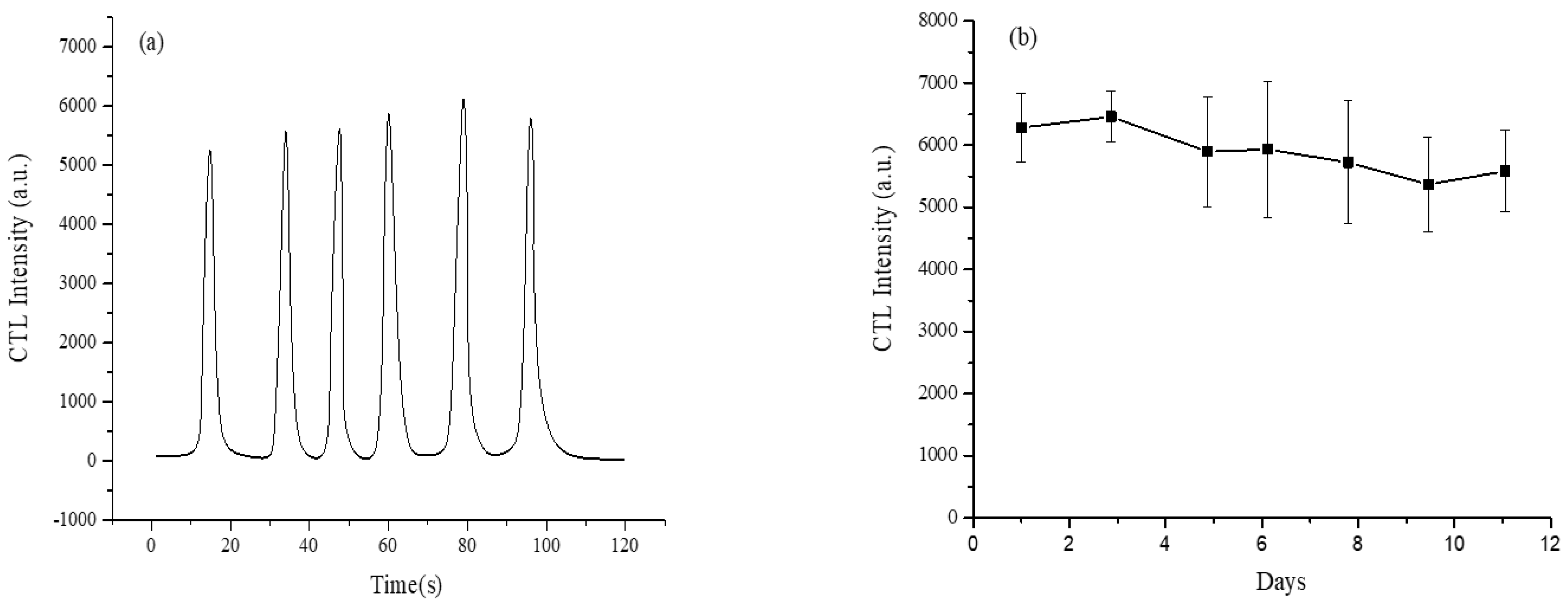
3.5. Selectivity, Repeatability and Stability of Sensor System

Since bad selectivity may lead to false positive results, selectivity is an important performance index for chemical sensors. Some common organic solvents and indoor air pollutants may interfere with the experimental results. Under optimized operating conditions, acetone was tested by introducing 1200 ppm of each compound at the same concentration into the sensor. As shown in Figure 11, there are emissions of ethanol and acetone. The luminous intensity of ether is only 7.5% of that of acetone, and that of ethanol is about 4.2% of that of acetone. This indicated that the sensor had good selectivity for acetone. The selectivity of the sensor can be determined by measuring the response generated by the interference gas of a specific concentration, that is, the sensor response generated by the target gas of a specific concentration. Cross-sensitivity reflects whether the measurement results are accurate, so the sensitivity and selectivity of the ideal sensor should be as high as possible. Clearly, the CuO-based luminescence sensor had better selectivity for acetone.
For verification of the reproducibility and stability of this luminescence system, the study was conducted by performing six replicate measurements during 100 s. Response-recovery time: Response time refers to the time it takes for the gas sensor signal to rise from 0 to 90% of the equilibrium signal value; recovery time refers to the time it takes for the sensor’s ventilation balance to return to 10% of the signal. In our study, response-recovery time was ‘Response time’+’ recovery time’. As shown in Figure 12a, the sensor displayed a fast response speed and recovery speed of within 4 s and within 20 s, respectively. The relative standard deviation (RSD, n = 6) of the six replicates was 4.1%, which indicated that the sensor had good reproducibility. To study the sensor’s stability, the luminous intensity of 900 ppm acetone can be measured every 24 h under optimized conditions. As shown in Figure 12b, when the sensor worked continuously for 168 h, there was no change in luminous intensity. The RSD of the repeated measurements of the seven experiments was 3.7%. Because the sensor shows good response and recovery speeds and long-term stability, the sensor can monitor acetone quickly and continuously for a long time.

3.6. Mechanism Discussion

According to the molecular information obtained by the wireless catalytic luminescence sensor, a possible mechanism is proposed. The catalytic reaction which described the transformation of an organic compound on the CuO surface included two processes: (1) There were a large number of active centers on CuO surface which can adsorb acetone. (2) The surface of CuO can catalyze and oxidize the adsorbed acetone. (3) The high luminescence is due to the formation of active intermediates [16,28].
When acetone vapor passed through the CuO surface and was adsorbed, it might be oxidized by O2 to active intermediates (CH3CO* or CO2*) under the catalysis of CuO. The catalytically oxidized of acetone on CuO surface for luminescence production may be as follows [29,30]:
CH3COCH3 + O2  CH3CO*
CH3CO* CH3CH2COOH + hv
or
CH3COCH3 + O2  CO2*
CO2* CO2 + hv
The active intermediates of CH3CO* or CO2* were unstable and released energy (hv) in the form of luminescence. The results made acetone have a high CTL signal.

3.7. Sample Analysis

For the sake of testing the feasibility of the sensor for determining acetone in a mixed gas, the composition of the air was simulated (20 times), and three test samples containing a known concentration of acetone were measured in a linear range to evaluate the practical application of the CTL sensor. Sample 1 was a mixture of 500 ppm acetone and methanol with the same concentration, Samples 2 were prepared by adding 500 ppm acetone to 500 ppm diethyl ether, and Samples 3 were prepared by adding 500 ppm acetone to 500 ppm ethanol, respectively. The three samples were analyzed by CTL sensor and the concentration of acetone was calculated by a linear regression equation based on CTL intensity (Table 1). Acetone in the three artificial samples was well-quantified and the recovery was satisfactory [31]. The results indicate that the sensor was used for routine monitoring of the effects of acetone in the air and control the quality of the acetone, methanol, and diethyl ether mixture.

4. Conclusions

At this stage, some theoretical and applied studies of Cataluminescence are still not mature enough and further research is still needed. For a sensor, the main indicators to evaluate performance are sensitivity, selectivity, stability, and response speed. In this study, a catalytic light-emitting sensor was constructed by using alkaline earth metal oxide CuO nanomaterials with abundant sources, simple preparation, and no noble metal doping as catalysts, and the rapid detection of acetone was realized. This method has low energy consumption, simple device construction, low cost, fast response, no sample pretreatment, and simple and easy operation, which improve the applicability of the Cataluminescence detection method. At the same time, this study also broadened the scope of Cataluminescence sensors application and has potential application value in the fields of industrial testing, food safety, and agricultural production.

Author Contributions

Conceptualization, X.S.; methodology, G.S.; software, Y.Z.; validation, G.S. and X.S.; formal analysis, G.S.; investigation, X.S.; data curation, X.S.; writing—original draft preparation, G.S.; writing—review and editing, S.W.; visualization, Y.Z.; project administration, Y.Z.; funding acquisition, G.S. and S.W. All authors have read and agreed to the published version of the manuscript.

Funding

This work was Funded by China Postdoctoral Science Foundation (No. 2021M692473), Natural Science Foundation of Anhui Province (2108085QF260), and The Open Research Fund of National Engineering Research Center for Agro-Ecological Big Data Analysis & Application, Anhui University (No. AE202103), Anhui Provincial Department of Education Research Project (KJ2021A0179), the Key Natural Science Research Project for Colleges and Universities of Anhui Province (KJ2021ZD0056).

Institutional Review Board Statement

Not applicable.

Informed Consent Statement

Not applicable.

Data Availability Statement

The data presented in this study are available in the article.

Conflicts of Interest

The authors declare no conflict of interest.

References

  1. Meng, F.; Lu, Z.; Zhang, R.; Li, G. Cataluminescence sensor for highly sensitive and selective detection of iso-butanol. Talanta 2019, 1630, 910–918. [Google Scholar] [CrossRef] [PubMed]
  2. Yu, S.; Zhang, D.; Zhang, Y.; Pan, W.; Meteku, B.E.; Zhang, F.; Zeng, J. Green light-driven enhanced ammonia sensing at room temperature based on seed-mediated growth of gold-ferrosoferric oxide dumbbell-like heteronanostructures. Nanoscale 2020, 36, 18815–18825. [Google Scholar] [CrossRef] [PubMed]
  3. Zhang, L.; Liu, T.; Ren, R.; Zhang, J.; He, D.; Zhao, C.; Suo, H. In situ synthesis of hierarchical platinum nanosheets-polyaniline array on carbon cloth for electrochemical detection of ammonia. J. Hazard. Mater. 2020, 392, 122342. [Google Scholar] [CrossRef] [PubMed]
  4. Wu, Y.; Peng, S.; Xie, Q.; Xu, P. Nonlinear least squares with local polynomial interpolation for quantitative analysis of IR spectra. Spectrochim. Acta Part A Mol. Biomol. Spectrosc. 2019, 206, 147–153. [Google Scholar] [CrossRef]
  5. Pfeifer, J.; Simon, M.; Heinritzi, M.; Piel, F.M.; Weitz, L.; Wang, D.S.; Granzin, M.; Müller, T.; Bräkling, S.; Kirkby, J.; et al. Measurement of ammonia, amines and iodine compounds using protonated water cluster chemical ionization mass spectrometry. Atmos. Meas. Tech. 2020, 13, 2501–2522. [Google Scholar] [CrossRef]
  6. Perraud, V.; Li, X.; Smith, J.N.; Finlayson-Pitts, B.J. Novel ionization reagent for the measurement of gas-phase ammonia and amines using a stand-alone atmospheric pressure gas chromatography (APGC) source. Rapid Commun. Mass Spectrom. 2019, 34, e8561. [Google Scholar] [CrossRef] [Green Version]
  7. Gu, G.; Zhu, H. A portable embedded explosion gas detection and identification device based on intelligent electronic nose system. Sens. Rev. 2016, 36, 57–63. [Google Scholar] [CrossRef]
  8. Shi, G.; He, Y.; Li, B.; Zuo, L.; Yin, B.; Zeng, W.; Ali, F. Analysis and modeling of wireless channel characteristics for Internet of Things scene based on geometric features. Future Gener. Comp. Syst. 2019, 101, 492–501. [Google Scholar] [CrossRef]
  9. Tang, Y.; Su, Y.; Yang, N.; Zhang, L.; Lv, Y. Carbon nitride quantum dots: A novel chemiluminescence system for selective detection of free chlorine in water. Anal. Chem. 2014, 9, 4528–4535. [Google Scholar] [CrossRef]
  10. Shi, G.; He, Y.; Luo, Q.; Li, B.; Zhang, C. Portable device for acetone detection based on cataluminescence sensor utilizing wireless communication technique. Sens. Actuators B Chem. 2018, 257, 451–459. [Google Scholar] [CrossRef]
  11. Koo, W.; Choi, S.; Kim, S.; Jang, J.; Tuller, H.L.; Kim, I. Heterogeneous sensitization of metal–organic framework driven metal@metal oxide complex catalysts on an oxide nanofiber scaffold toward superior gas sensors. J. Am. Chem. Soc. 2016, 138, 13431–13437. [Google Scholar] [CrossRef] [PubMed]
  12. Chu, Y.; Zhang, Q.; Li, Y.; Xu, Z.; Long, W. A cataluminescence sensor for propionaldehyde based on the use of nanosized zirconium dioxide. Microchim. Acta 2014, 181, 1125–1132. [Google Scholar] [CrossRef]
  13. He, H.; Zhang, D.; Guo, F.; Sun, F. A versatile microporous zinc (II) metal–organic framework for selective gas adsorption, cooperative catalysis, and luminescent sensing. Inorg. Chem. 2018, 57, 7314–7320. [Google Scholar] [CrossRef] [PubMed]
  14. Zhang, R.; Cao, X.; Liu, Y.; Chang, X. Development of a simple cataluminescence sensor system for detecting and discriminating volatile organic compounds at different concentrations. Anal. Chem. 2013, 85, 3802–3806. [Google Scholar] [CrossRef]
  15. Liu, W.; Wang, Y.; Bai, Z.; Li, Y.; Wang, Y.; Chen, L.; Xu, L.; Diwu, J.; Chai, Z.; Wang, S. Hydrolytically stable luminescent cationic metal organic framework for highly sensitive and selective sensing of chromate anions in natural water systems. ACS Appl. Mater. Int. 2017, 19, 16448–16457. [Google Scholar] [CrossRef]
  16. Shi, G.; He, Y.; Zhang, Y.; Yin, B.; Ali, F. Detection and determination of harmful gases in confined spaces for the Internet of Things based on cataluminescence sensor. Sens. Actuators B Chem. 2019, 296, 126686. [Google Scholar] [CrossRef]
  17. Cheng, H.; Zhou, Z.; Liu, T. Electro-spinning fabrication of nitrogen, phosphorus co-doped porous carbon nanofiber as an electro-chemiluminescent sensor for the determination of cyproheptadine. RSC Adv. 2020, 39, 23091–23096. [Google Scholar] [CrossRef]
  18. Shen, C.; Lou, Q.; Liu, K.; Dong, L.; Shan, C. Chemiluminescent carbon dots: Synthesis, properties, and applications. Nano Today 2020, 35, 100954. [Google Scholar] [CrossRef]
  19. Wang, J.; Jiang, M.; Yan, L.; Peng, R.; Huangfu, M.; Guo, X.; Li, Y.; Wu, P. Multifunctional Luminescent Eu (III)-Based Metal–Organic Framework for Sensing Methanol and Detection and Adsorption of Fe (III) Ions in Aqueous Solution. Inorg. Chem. 2016, 55, 12660–12668. [Google Scholar] [CrossRef]
  20. Tantubay, K.; Das, P.; Sen, M.B. Ternary reduced graphene oxide–CuO/ZnO nanocomposite as a recyclable catalyst with enhanced reducing capability. J. Environ. Chem. Eng. 2020, 8, 103818. [Google Scholar] [CrossRef]
  21. Sharma, G.P.; Bansal, A.; Singh, R. Thermal coefficients of Earth fuller reinforced with nano-oxide particles. Nano Express 2021, 2, 010024. [Google Scholar] [CrossRef]
  22. Zhang, Y.; Zhang, J.; Jiang, Y.; Duan, Z.; Liu, B.; Zhao, Q.; Wang, S.; Yuan, Z.; Tai, H. Ultrasensitive flexible NH3 gas sensor based on polyaniline/SrGe4O9 nanocomposite with ppt-level detection ability at room temperature. Sens. Actuators B Chem. 2020, 319, 128293. [Google Scholar] [CrossRef]
  23. Chow, D.M.; Sinefeld, D.; Kolkman, K.E.; Ouzounov, D.G.; Akbari, N.; Tatarsky, R.; Bass, A.; Xu, C.; Fetcho, J.R. Deep three-photon imaging of the brain in intact adult zebrafish. Nat. Methods 2020, 17, 605–608. [Google Scholar] [CrossRef] [PubMed]
  24. Gao, D.; Yang, G.; Li, J.; Zhang, J.; Zhang, J.; Xue, D. Room-temperature ferromagnetism of flowerlike CuO nanostructures. J. Phys. Chem. C 2010, 114, 18347–18351. [Google Scholar] [CrossRef]
  25. Wang, X.; Xi, G.; Xiong, S.; Liu, Y.; Xi, B.; Yu, W.; Qian, Y. Solution-phase synthesis of single-crystal CuO nanoribbons and nanorings. Cryst. Growth Des. 2007, 7, 930–934. [Google Scholar] [CrossRef]
  26. Huang, X.; Huang, Z.; Zhang, L.; Liu, R.; Lv, Y. Highly efficient cataluminescence gas sensor for acetone vapor based on UIO-66 metal-organic frameworks as preconcentrator. Sens. Actuators B Chem. 2020, 312, 127952. [Google Scholar] [CrossRef]
  27. Khnykov, A.Y.; Vdovichenko, A.Y.; Morozov, P.V.; Zavyalov, S.A.; Shevchenko, V.G.; Chvalun, S.N. Gas-sensing properties of poly (p-xylylene)-Titanium thin film nanocomposite, prepared by vapor deposition polymerization. Sens. Actuators B Chem. 2020, 320, 128367. [Google Scholar] [CrossRef]
  28. Li, L.; Hu, Y.; Deng, D.; Song, H.; Lv, Y. Highly sensitive cataluminescence gas sensors for 2-butanone based on g-C3N4 sheets decorated with CuO nanoparticles. Anal. Bioanal. Chem. 2016, 408, 8831–8841. [Google Scholar] [CrossRef]
  29. Zeng, N.; Long, Z.; Wang, Y.; Sun, J.; Ouyang, J.; Na, N. An acetone sensor based on plasma-assisted cataluminescence and mechanism studies by online ionizations. Anal. Chem. 2019, 91, 15763–15768. [Google Scholar] [CrossRef]
  30. Wang, S.; Shi, W.; Lu, C. Chemisorbed oxygen on the surface of catalyst-improved cataluminescence selectivity. Anal. Chem. 2016, 88, 4987–4994. [Google Scholar] [CrossRef]
  31. Watanabe, E.; Seike, N. Detection of herbicide clopyralid at nanogram per gram level in agricultural products using easy-to-use micro liquid–liquid extraction followed by analysis with ultraperformance liquid chromatography–tandem mass spectrometry. J. Chromatogr. A 2020, 1630, 461578. [Google Scholar] [CrossRef] [PubMed]
Figure 1. Diagram of the online wireless Cataluminescence sensor system.
Chemosensors 10 00179 g001
Figure 2. General schematic diagram of the wireless CTL harmful gas online detection system.
Chemosensors 10 00179 g002
Figure 3. (a) X-ray diffractometer pattern, (b) SEM, and (c) TEM images of the hierarchical CuO microspheres assembled from nano-sheets.
Chemosensors 10 00179 g003
Figure 4. The Cu2p XPS spectrum of CuO microspheres assembled with nano-sheets.
Chemosensors 10 00179 g004
Figure 5. Selection of the optimal carrier gas flow rate (temperature: 220 °C, wavelength: 425 nm, concentration: 200 ppm).
Chemosensors 10 00179 g005
Figure 6. The luminescence intensity of acetone changed with different wavelengths (temperature: 220 °C, flow rate: 310 mL/min, concentration: 500 ppm).
Chemosensors 10 00179 g006
Figure 7. Different CTL signal spectra separated by multiple wavelength channels.
Chemosensors 10 00179 g007
Figure 8. The luminescence intensity of acetone changed with different temperatures (wavelength: 590 nm, flow rate: 310 mL/min, concentration: 200 ppm).
Chemosensors 10 00179 g008
Figure 9. The calibration curve for acetone (temperature: 210 °C, flow rate: 310 mL/min, wavelength: 590 nm).
Chemosensors 10 00179 g009
Figure 10. CTL response profiles of ethanol with (a) acetone and (b) diethyl ether and (c) signal values (flow rate: 310 mL/min, temperature: 220 °C, wavelength: 590 nm).
Chemosensors 10 00179 g010
Figure 11. The luminescence responses of different gases (flow rate: 310 mL/min, temperature: 220 °C, wavelength: 590 nm, concentration: 1200 ppm).
Chemosensors 10 00179 g011
Figure 12. (a) Typical results obtained from six replicate determinations of acetone within 100 s. (b) The change trend of the luminescence intensity of acetone within one week (168 h). Flow rate: 310 mL/min, working temperature: 220 °C, wavelength: 590 nm, concentration: 900 ppm.
Chemosensors 10 00179 g012
Table 1. Determination Result of Acetone in Artificial Samples.
Sample No.CompositionSpiked Values (ppm)Acetone Measured Values (ppm)Average CTL IntensityRecovery
Time (s)
1Acetone (500 ppm)498.4481.1 ± 0.6402397% × Tacetone
Methanol (500 ppm)482.9
2Acetone (500 ppm)488.9476.9 ± 1.14269101% × Tacetone
Diethyl ether (500 ppm)473.3
3Acetone (500 ppm)479.1486.4 ± 0.3410894% × Tacetone
Ethanol (500 ppm)485.2
Publisher’s Note: MDPI stays neutral with regard to jurisdictional claims in published maps and institutional affiliations.

