Load Capacity of Shallow Embedded Anchor Channels


1
Jordahl, 12057 Berlin, Germany
2
Institute of Construction Materials and Materials Testing Institute, University of Stuttgart, 70569 Stuttgart, Germany
*
Author to whom correspondence should be addressed.
CivilEng 2020, 1(3), 243-252; https://0-doi-org.brum.beds.ac.uk/10.3390/civileng1030015
Submission received: 8 September 2020
/
Revised: 18 October 2020
/
Accepted: 29 October 2020
/
Published: 31 October 2020
(This article belongs to the Special Issue Connections in Concrete)
Abstract
:Anchor channels are cast in concrete and allow the connection of components using channel bolts. In recent years, the design to value resulted in ever thinner concrete elements, which often cannot accommodate the required embedment depth of standard anchor channels. For this reason, channels may be fitted with short anchors. While existing design provisions allow for the calculation of the tension capacity also for shallow embedded anchor channels, tests are required to determine product-specific parameters for the economic shear loads design. The presented study investigated the performance of shallow embedded anchor channels tested in shear. The detailed evaluation of the test data demonstrates that testing of the minimum embedment is conservative and that the load-displacement behavior of channels with welded I-sections is comparable to that of channels with forged headed studs. In addition, a new evaluation approach is proposed.
1. Introduction
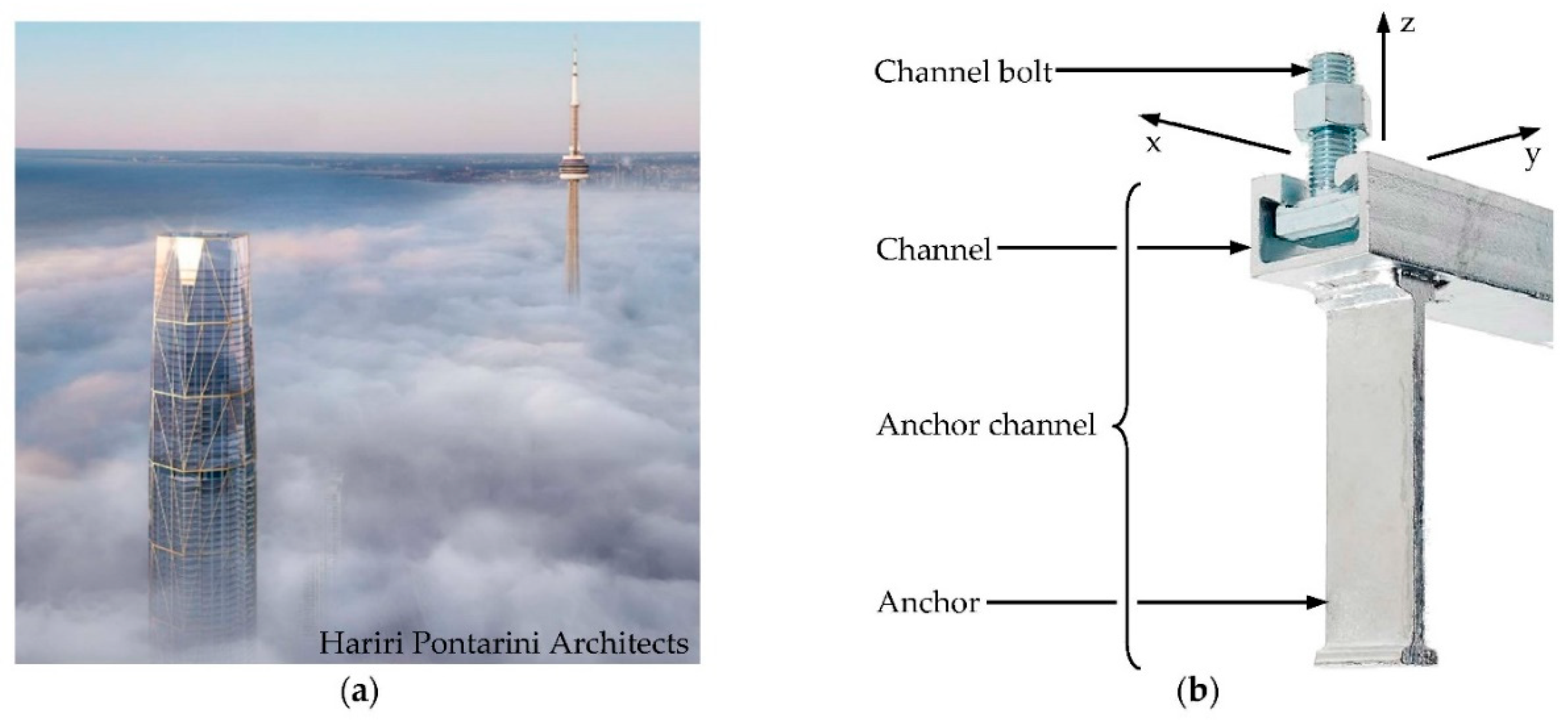
Anchor channels with channel bolts allow versatile possibilities to conveniently and reliably connect components to reinforced concrete structures. Qualified anchor channel–channel bolt-systems reliably take up static and cyclic loads even under extreme conditions to be anticipated, e.g., for the anchoring of brackets holding curtain wall elements of supertall skyscrapers which are subjected to high dead and wind loads (Figure 1a).
Anchor channels consist of anchors either forged or welded to C-channels which are cast flush in reinforced concrete elements and allow, after stripping of the formwork, the installation of matching T-bolts, aka channel bolts (Figure 1b). These anchor channel–channel bolt-systems can take up high tension loads (N in z-direction) and shear loads (V in x- and y-direction) by mechanical interlock [1,2], making the system very robust and even suitable to withstand explosive loads [3,4], seismic loads [5,6], and fatigue loads [7,8]. The possibility of fixing the channel bolts at any location along the length of the channel offers higher flexibility to the designer than other cast-in systems such as baseplates with headed studs.
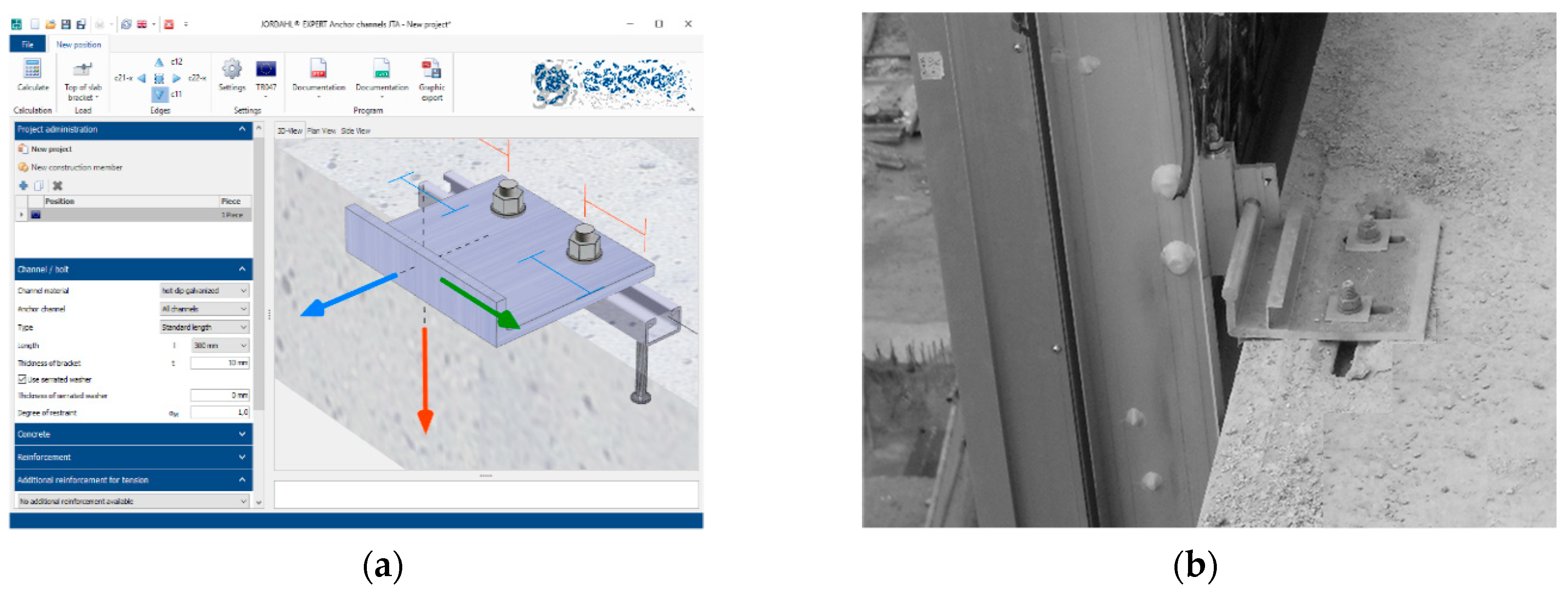
The design of the anchor channel and channel bolt requires the verification for almost 20 possible failure modes and partly involves product-specific parameters to be determined by testing. In Europe, the design provisions for concrete anchors including anchor channels and channel bolts are provided in EN 1992-4 [9], i.e., Part 4 of the Eurocode 2. The design code for concrete structures in the USA, ACI 318 [10], stipulates design rules for single-point concrete anchors. The design rules for anchor channels and channel bolts are not yet included. For this reason, amendments are provided in AC232 [11], the Acceptance Criteria for anchor channel with channel bolts in the USA, defining required qualification tests to attain Evaluation (Service) Reports (E(S)R). In Europe, product qualification is certified by European Technical Assessment (ETA) documents for which qualification tests have to be carried out according to the European Assessment Document (EAD) 330008-03-0601 [12]. Due to the complexity of the design provisions, structural engineers typically use proprietary software to design anchor channels and channel bolts (Figure 2a).
The qualification and design regulations of anchor channels and channel bolts are almost identical in Europe and the USA, though some minor differences still call for harmonization [13]. While both standard frameworks do not require product-specific parameters to design for tension loading, they do require product-specific parameters to allow the economic design for shear loading.
To determine the product-specific parameters, tests are carried out on anchor channels installed in concrete. Test data presented below verifies that also shallow embedded anchor channels can transfer shear loads safely despite their reduced embedment. Shallow embedded anchor channels are popular particularly for the connection of curtain wall brackets (Figure 2b) where value engineering led to thin concrete decks, however, interestingly their general load-displacement behavior has not been discussed nor performance data or approval reports published to date.
2. Background on Design Provisions for Concrete Edge Breakout Shear Capacity
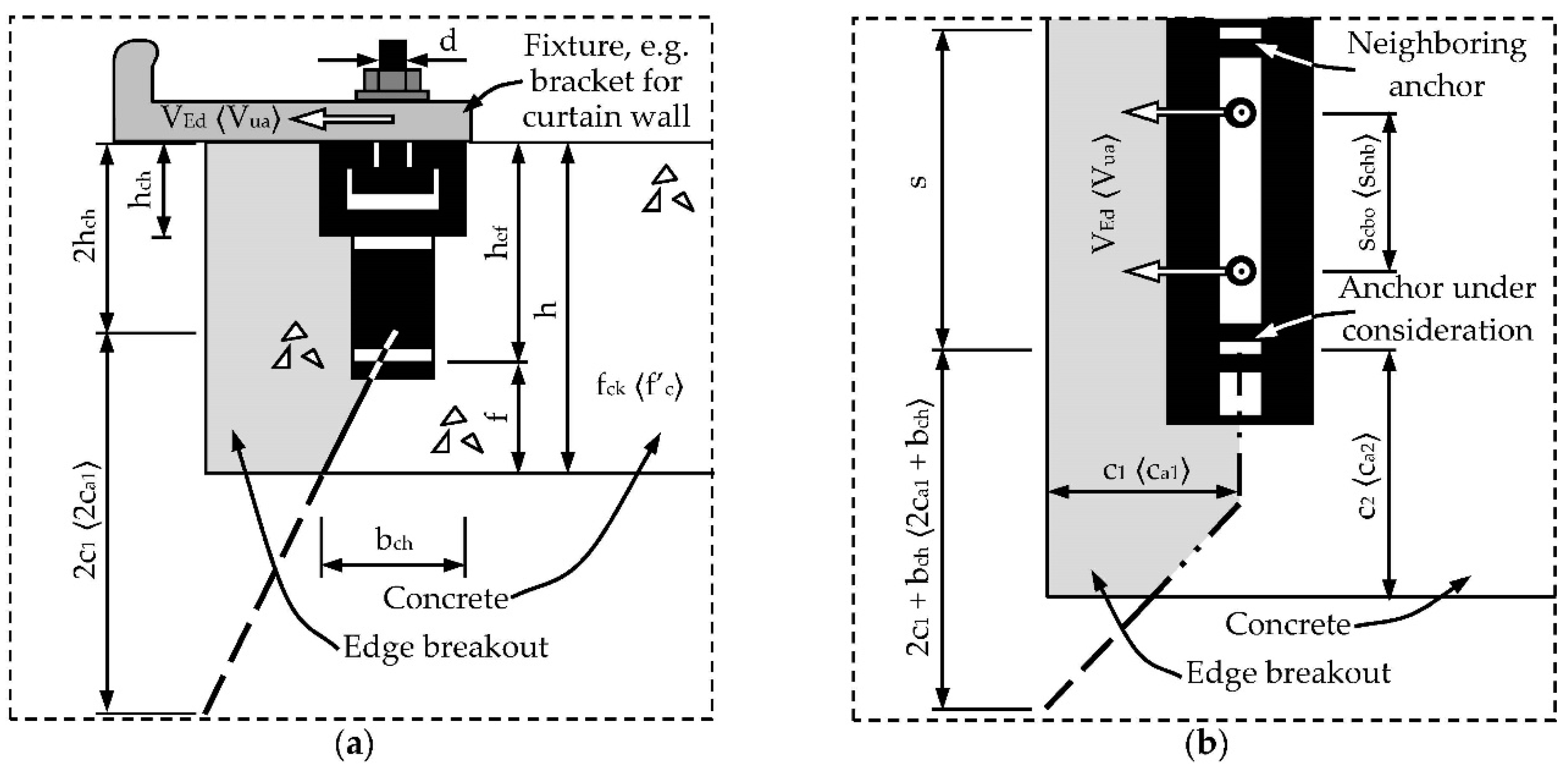
The design of anchor channels is complex. For those interested in the background of the design for concrete edge breakout shear capacity, the underlying provisions are explained to the required level of detail. In the following, the denomination according to the European standard framework is used for the parameter notation. Deviating US-American denomination is provided in angle brackets (“⟨…⟩”). The overall load capacity is defined as the minimum of all capacities determined for the individual failure modes. The most relevant failure mode under shear is the concrete edge breakout, which is critical if the anchor channel is installed in a thin slab and with a small edge distance. This situation is typical for the installation of brackets carrying curtain wall elements (Figure 3).
For the design, the load from the channel bolts is assumed to be distributed by the channel to the anchors for which the design check of concrete edge breakout is carried out. The characteristic ⟨nominal⟩ concrete edge breakout capacity of the individual anchor of a channel loaded perpendicular to the concrete edge is calculated by:
VRk,c = VRk,c0 · Ψch,s,V · Ψch,c,V · Ψch,h,V · Ψre,V
⟨Vcb = Vb · Ψs,V · Ψco,V · Ψh,V · Ψc,V⟩
The modification factors Ψch,c,V ⟨Ψco,V⟩, Ψch,h,V ⟨Ψh,V⟩, and Ψre,V ⟨Ψc,V⟩ take into account the condition (uncracked/cracked) and the geometry of concrete member (c1 ⟨ca1⟩, c2 ⟨ca2⟩, h) as well as the detailing of surface reinforcement ⟨supplementary reinforcement⟩. In the context of the tests presented below, these modification factors are 1.0 since the concrete test members used for qualification are designed without reinforcement and with sufficiently large corner distances c2 ⟨ca2⟩ and heights h to allow the development of a full breakout body. The influence of neighboring anchors, i.e., the effect of location and loading of adjacent anchors, however, is relevant and is considered by the modification factor:
Ψch,s,V = 1/(1 + (1 − s/(4c1 + 2bch)1.5))
⟨Ψs,V = 1/(1 + (1 − s/(4ca1 + 2bch)1.5))⟩
These equations assume that the conditions bch/hef ≤ 0.7 and hch/hef ≤ 0.4 ⟨hch/hef ≤ 0.5⟩ are fulfilled—which is assumed in the following.
The core of Equation (1) is the basic characteristic ⟨nominal⟩ resistance ⟨strength⟩ against concrete edge breakout failure VRk,c0 ⟨Vb⟩ of an individual anchor considered. The research forming the basis for the design and qualification of anchor channels [14] showed that the shear capacity VRk,c0 ⟨Vb⟩ is increasing with the edge distance c1 ⟨ca1⟩ by the power of 1.5. This is the same power applied on the anchor embedment hef to calculate the tension capacity. This approach is also in line with the design of concrete anchors, i.e., post-installed anchors and cast-in headed studs of anchor plates. Results of shear tests on concrete anchors [15] were later used to reason the decrease of the power from 1.5 to 4/3:
VRk,c0 = k12 · fck0.5 · c14/3
⟨Vb = αch,V · f’c0.5 · ca14/3⟩
This approach disadvantages anchor channels if compared to concrete anchors. It is noteworthy, however, that the concrete edge capacity of concrete anchors, paradoxically, is still calculated as a function of c11.5 ⟨ca11.5⟩. The loss of calculated capacity due to the reduction is about 20% for a typical small edge distance of 75 mm and is progressively increasing with larger edge distances. While fck ⟨f’c⟩ is the characteristic ⟨nominal⟩ concrete strength for the specific design case, k12 ⟨αch,V⟩ is a semi-empiric factor. Originally, staggered default values were defined for common small, medium, and large anchor channel sizes [16]. Later, the CUAP 06.01/01 [17], the origin of AC232 and EAD 330008-03-0601, defined only one conservative default value equaling to 4.5 ⟨4.0⟩ valid today for all anchor channels. Optional qualification tests are required to determine product-specific values for the shear capacity factor k12 ⟨αch,V⟩. These qualification tests are introduced in the following section.
3. Qualification Tests to Determine Product-Specific Shear Capacity Factors
Equation (3) is rearranged to determine the product-specific shear capacity factor k12 ⟨αch,V⟩, which has to be determined for every combination of channel type and anchor type. The factor k12 = kcr,V ⟨αch,V⟩ refers to cracked concrete, whereas uncracked concrete test members are used for qualification testing. To compensate for the capacity reduction associated with cracked concrete, the equation is divided by 1.4 ⟨multiplicated by 0.7⟩ [18]. Moreover, AC232 and EAD 330008-01-0601 cap the value of the shear capacity factor to 7.5 to avoid that shear capacity factors are deduced which are—due to the large scatter caused by the concrete—by chance higher than the range of experience:
kcr,V = 1/1.4 ∙ min{Vk; 0.75Vm}/(fc,test0.5 ∙ c14/3 · Ψch,s,V) ≤ 7.5
⟨αch,V = 0.7 ∙ min{Vk; 0.75Vm}/(fc,test0.5 ∙ ca14/3 · Ψs,V) ≤ 7.5⟩
Vk stands for the characteristic (5% quantile, determined under the assumption of a normal distribution with 0.9 as the coefficient of confidence) and Vm for the mean failure load of the test series not normalized to the concrete strength (Vk(nom)/f’c0.5 = Vk(test)/fc,test0.5). The term min{Vk; 0.75Vm} represents a minimum scatter to be assumed even if the tests show a lower scatter. This equals to a 7.4% coefficient of variation for five test repeats (solving Vk = 0.75Vm ⇔ Vm × (1 − k × v/100) = 0.75Vm ⇔ v = 25/k, where k = 3.401 for n = 5 [19]).
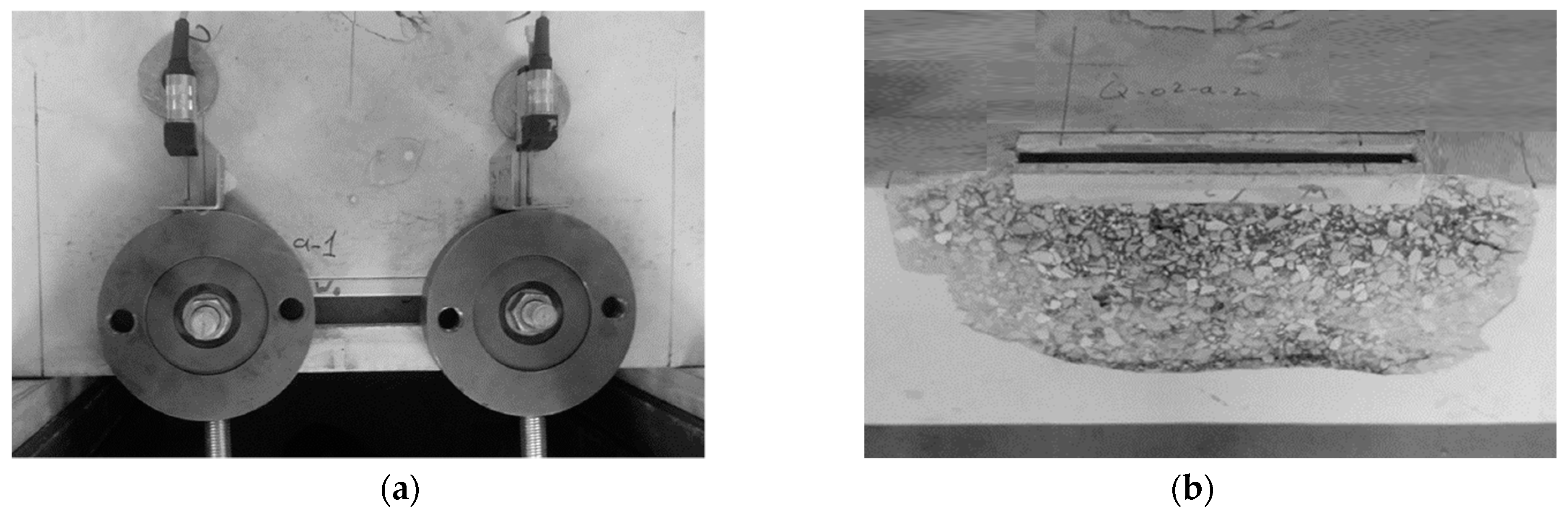
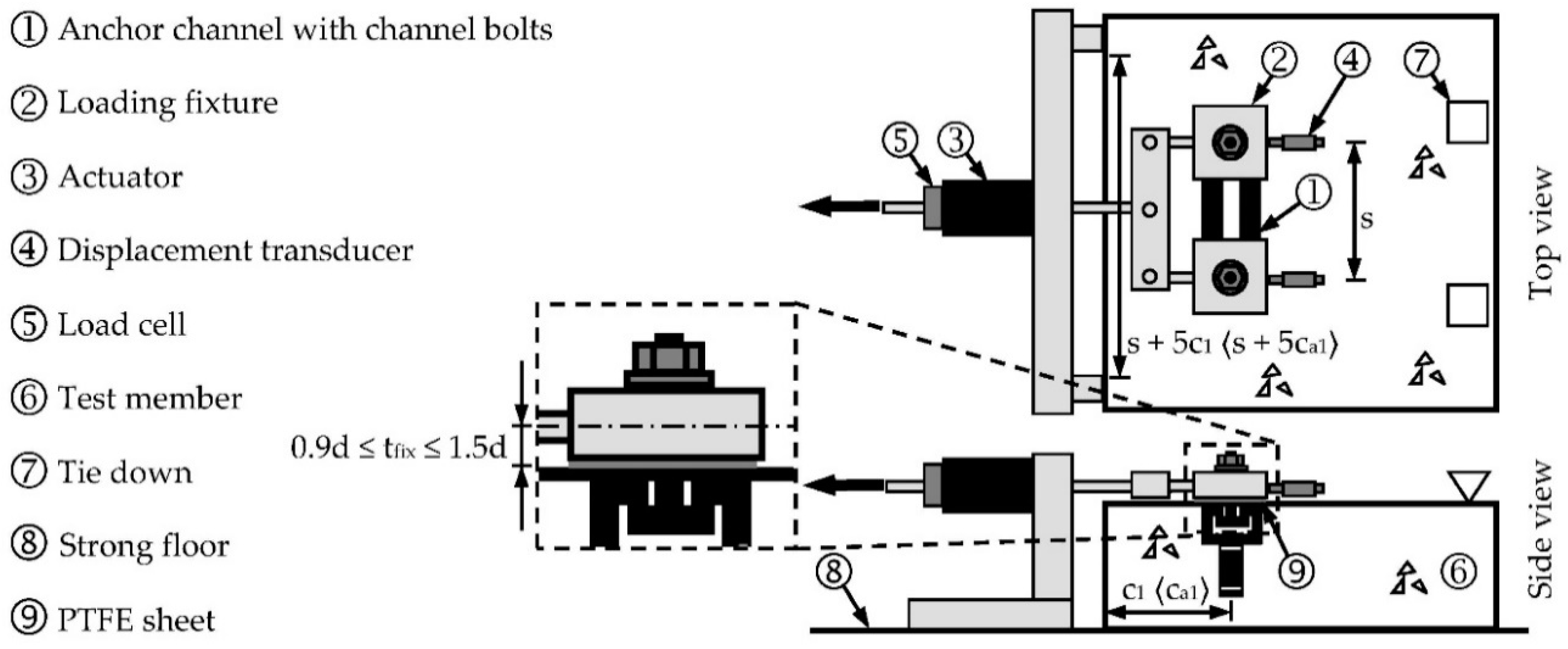
In principle, neither qualification nor design rules distinguish between forged anchors, which are headed studs, and welded anchors, which are generally pieces of I-sections. For the tests, the anchor channels are cast in concrete test members, parallel to the edge at a distance of c1 ⟨ca1⟩ corresponding to the minimum value for which qualification is sought (Figure 4 and Figure 5). The test member thickness is large enough to avoid an influence on the failure load (h > hcr,V) and to accommodate a support outside the width of the anticipated breakout body (s + 5c1 ⟨s + 5c1a⟩). Tie downs counteract the uplifting force due to the eccentrically acting actuator. A balance beam transfers the load equally to the two channel bolts. A load cell and two displacement transducers touching the fixture allow the recording of load and displacement. It is noted that the displacement may also be measured somewhere between the actuator and fixture. The location of measurement influences the recorded load-displacement behavior; this effect is briefly discussed in the next section.
4. Test Program to Study Product-Specific Shear Capacity Factors
The aim of the test program (Table 1) was to determine product-specific shear capacity factors of shallow embedded anchor channels (hch/hef ≳ 0.35). The results were used for further studies on the load-displacement behavior and comparison with amended tests on standard embedded anchor channels (hch/hef ≲ 0.35). Moreover, the potential difference in the performance of channels with welded anchors (40-S, 50-S, 53-S, 55-S, 40-L, 53-L) and forged anchors (53-L°) was investigated. Note that currently all commercially available channels suitable for shallow embedment are fitted with welded anchors. Each test series comprised five test repeats. Channels of four different sizes with two anchors at a spacing of 250 or 300 mm were tested. The edge distance c1 ⟨c1a⟩ was between 50 and 100 mm. The channel bolt diameters were large enough to ensure that concrete edge breakout failure is governing. The tests were part of two test campaigns carried out at accredited test labs.
5. Test Results Used for Evaluating the Product-Specific Shear Capacity Factors
All anchor channels failed in concrete edge breakout mode. The scatter of the ultimate load was generally well below the acceptance criteria of v = 20% [12] (Table 2). The channels fitted with long anchors for standard embedment showed a very low scatter with a coefficient of variation of around 5%, whereas the coefficient of variation of the channels fitted with short anchors for shallow embedment was significantly higher, between 6.2% and 13.6%. The total mean and characteristic values Vk are divided by 2 (relating to 1 anchor) to calculate the shear capacity factors kcr,V ⟨αch,V⟩ (Equation (4)), taking into account the concrete strength fck ⟨f’c⟩ and the modification factor Ψch,s,V ⟨Ψs,V⟩ (Equation (2)). Note that all tested anchor channels successfully passed through the complete qualification program of which the presented tests are an excerpt.
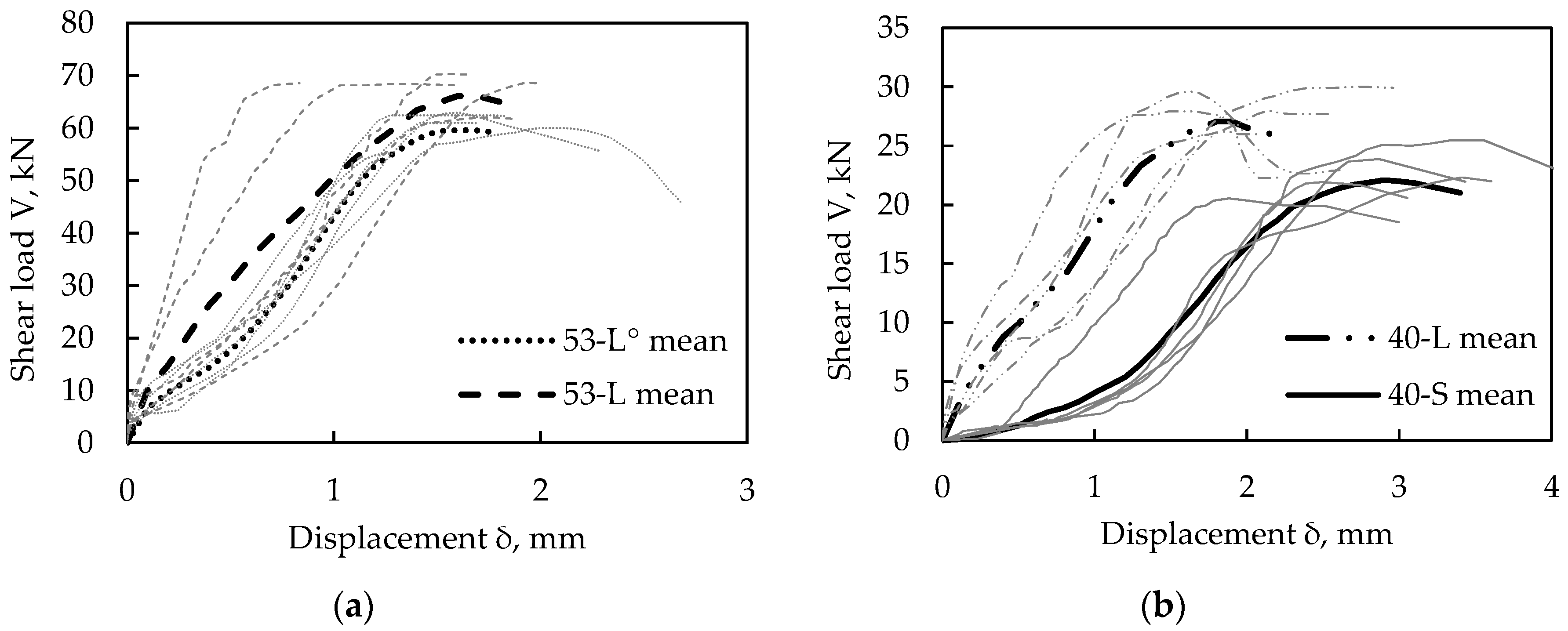
In general, the load-displacement curves showed a mixed ductile–brittle behavior (Figure 6) because the primary brittle concrete edge breakout is combined with the secondary ductile bending of anchor and channel. The set of curves have a large band of scatter about the displacement, common for this kind of test. The large scatter is the result of the random play between fixture hole and channel bolt, the slip of the bolt in the channel during loading, elastic deformation of the steel as well as slackness within the connecting devices between the actuator and channel bolt if the displacement transducers are not placed directly at the fixture. The displacement, however, is not an acceptance criterion for the qualification of anchor channel–channel bolt-systems since it is not critical for their robust load-bearing behavior.
The comparison of the channels with forged anchors, 53-L°, and the channels with welded anchors, 53-L, shows a very similar overall load-displacement behavior (Figure 6a). Note that the two test series were part of different test campaigns where the transducers measuring the displacement were set up differently, therefore resulting in differences in the measured stiffness. The ultimate mean load of channels with long anchors for standard embedment, 40-L, was about 25% above that of short anchors for shallow embedment, 40-S (Figure 6b) because the activated concrete is influenced by the embedment depth differing by almost 40%.
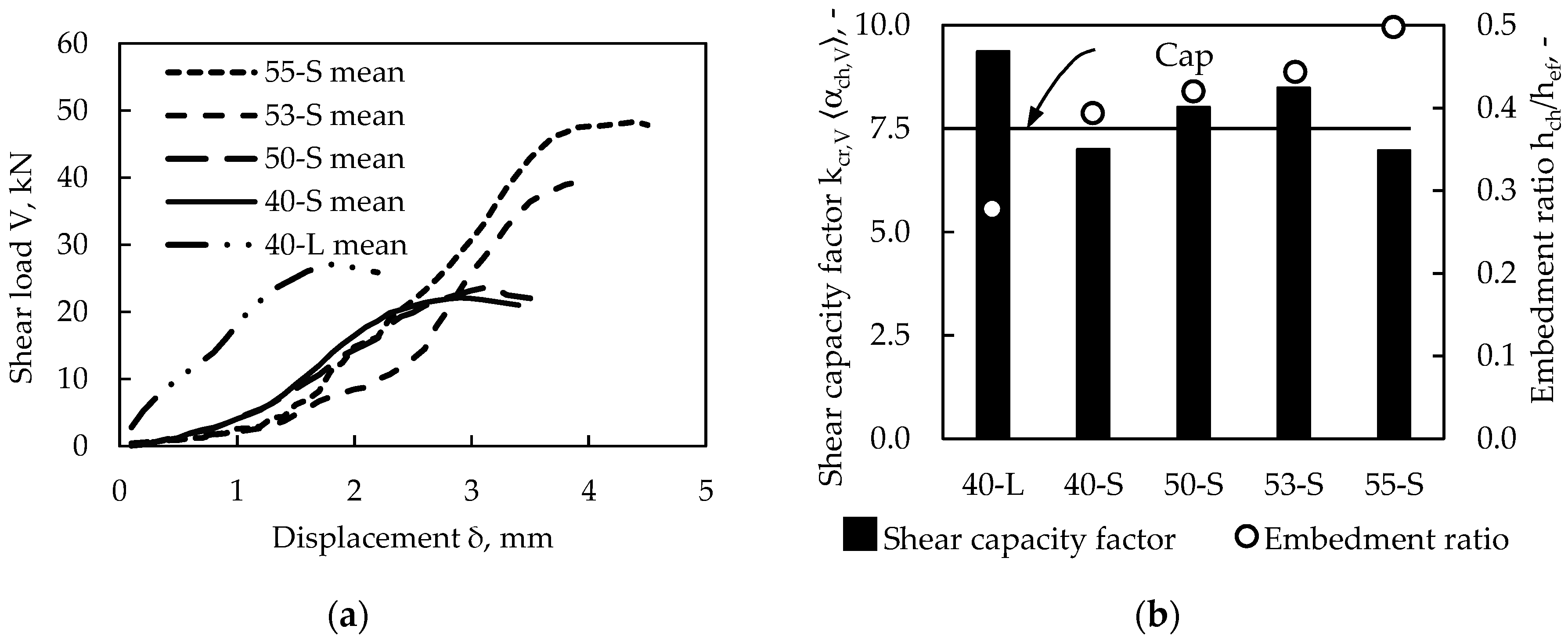
The substantial load reduction can also be observed when comparing all tested anchor channels made of welded I-sections for standard embedment and shallow embedment (Figure 7a): The mean load-displacement curves of 55-S, 53-S, 50-S, and 40-S showed a very similar stiffness. Naturally and in line with previous research [14,20], larger anchor channels sustained higher shear loads and failed at larger displacements if compared with smaller anchor channels. Test series 40-L showed a different shape of the mean load-displacement curve because it was part of the other test campaign with differences in the test setup of the displacement transducers.
All tested anchor channels developed shear capacity factors which are more than 60% larger than the default value of 4.5 ⟨4.0⟩, making qualification tests imperative for economic reasons. The medium-sized anchor channels for shallow embedment, 50-S and 53-S, even exceeded the cap for the shear capacity factor of 7.5 (Figure 7b, black columns). Interestingly to note that, by trend, the shear capacity factor increases with larger anchor channel types though the anchors were shorter for the same overall depth including the height of the channel resulting in larger embedment ratios hch/hef (Figure 7b, white circles).
6. Discussion
The test data allow for the calculation of the specific shear capacity factors considering the influence of adjacent anchors and the concrete strength of the test member (Equation (4)). The tests fulfilled the requirements of the qualification regulations and the shear capacity factor was determined as a product-specific parameter required for qualification certificates. In addition, the test data allow for the general implications for the qualification of anchor channels.
In general, the scatter of the ultimate shear loads of anchor channels for standard embedment is low. A larger influence of the ductile steel bending of the long anchor if compared to the brittle concrete edge breakout may be the reason. In contrast, the scatter of the ultimate shear loads of anchor channels for shallow embedment is partly two times higher. Here, the short anchors cannot sufficiently counteract the scatter of the concrete edge breakout.
The comparison of the shear capacity factors of the test series 40-L and 40-S shows that larger embedment depths develop larger shear capacities and thus shear capacity factors. Testing a minimum embedment depth hef with otherwise identical conditions, i.e., the same edge distance, is therefore conservative. It can be observed, moreover, that the reduction in shear capacity is not proportional to the reduction of embedment depth. This is because the shear capacity is, to a large extent, generated by the channel, which remains the same also if the length of anchors is reduced for shallow embedment.
The comparable overall load-displacement behavior of the channels with forged anchors, 53-L°, and the channels with welded anchors, 53-L, allow for the generalization of the findings for channels with both types of anchors. According to the current requirements, however, the ultimate load has to be tested for all channels fitted with different anchors (welded and forged) individually to deduce specific shear capacity factors.
The shear capacity factor of test series 55-S, which channels were manufactured with the relatively shortest anchors (hch/hef = 0.5), did not follow the overall trend only because of its large, though acceptable scatter reduced the calculated shear capacity substantially. This suggests that the scatter originates from the concrete material since there is no variation of the material and geometry of the anchor channels including the edge distance.
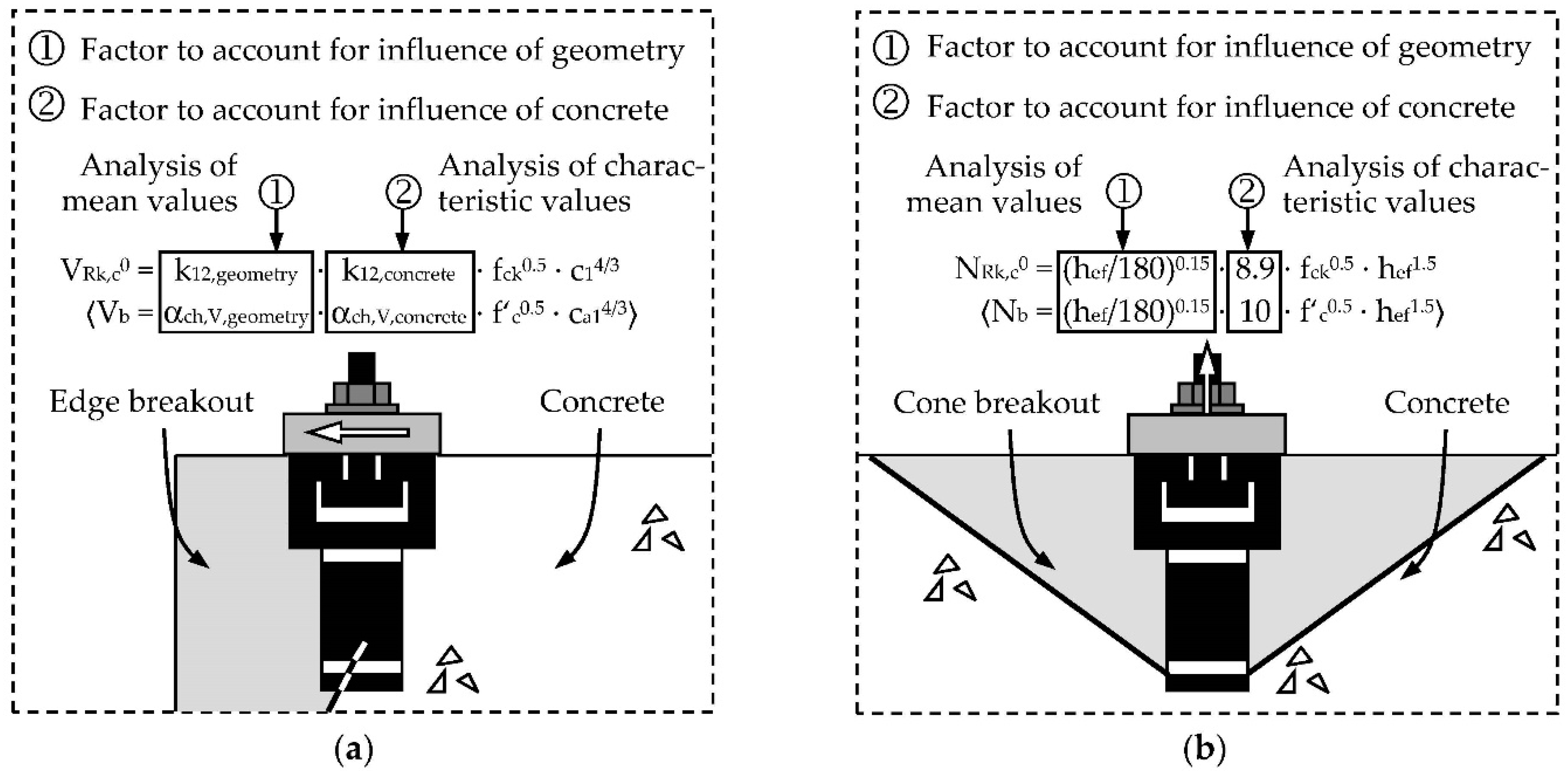
Further studies are required to allow for the separation of the k12 ⟨αch,V⟩ factor into two components to account for the influence of geometry (without scatter) and concrete material (with scatter) independently (Figure 8a). Future tests may also allow for the definition of the two components either as constant values or functions of the anchor channel geometry including the edge distance analog to the calculation of the concrete cone breakout capacity for tension load (Figure 8b): To this end, a function of the embedment depth derived based on mean test values [21] accounts for the influence of the geometry of the specific anchor channel, and a constant value developed on the analysis of characteristic test values [18] takes into account the influence of the scattering concrete material.
7. Summary and Conclusions
Increasingly lean design of reinforced concrete structures leads to ever-smaller concrete members, impeding the installation of standard embedded anchor channels with long anchors. For this reason, shallow embedded anchor channels with short anchors are needed. In contrast to the design of anchor channels under tension, a product-specific factor must be determined by testing to enable an economic design of anchor channels under shear loads. Although the qualification and design regulations already include shallow embedded anchor channels, no data of tests on channel bolts installed in shallow embedded anchor channels has been published to date.
The test data presented in this contribution closes this gap. The shear tests on shallow embedded anchor channels developed a load-displacement behavior not significantly different from that of anchor channels with standard embedment irrespective of whether the anchors were forged or welded to the channels. The shear capacity factor of shallow embedded anchor channels decreased if compared with standard embedded anchor channels. Testing the smallest embedment depth is therefore conservative.
The test data further revealed that the influence of the anchor channel geometry has to be separated from that of the concrete material to allow for an increased utilization of the shear capacity of anchor channels. This is particularly important for shallow embedded anchors typically used close to the edge of the concrete member. Further research is required.
Author Contributions
Conceptualization, C.M.; formal analysis, C.M. and A.S.; writing—original draft preparation, C.M.; writing—review and editing, C.M. and A.S. All authors have read and agreed to the published version of the manuscript.
Funding
This research received no external funding.
Conflicts of Interest
The authors declare no conflict of interest.
Disclaimer
Opinions, conclusions, and recommendations expressed in this paper are those of the authors only and do not necessarily reflect those of the authors’ affiliations.
References
- Konertz, D.; Kocur, G.; Clauß, F.; Häusler, F.; Mark, P. Anchor channels under 3D-load interaction—New approaches to load distributions and design. In Proceedings of the Fib Symposium on Concrete—Innovations in materials, design and structures, Krakow, Poland, 27–29 May 2019. [Google Scholar]
- Konertz, D.; Mahrenholtz, C.; Mark, P. Verification of a load distribution model for anchor channels in the experimental virtual lab. In Proceedings of the Concrete 2019 Conference, Sydney, Australia, 8–11 September 2019. [Google Scholar]
- Bedon, C.; Amadio, C. Passive control systems for the blast enhancement of glazing curtain walls under explosive loads. Open Civ. Eng. J. 2017, 11, 396–419. [Google Scholar] [CrossRef] [Green Version]
- Förch, M.; Wellershoff, F.; Lori, G.; Zobec, M.; Casucci, D.; Großer, R. Experimental testing of dissipative façade brackets. In Proceedings of the COST Action TU1403 Adaptive Facades Network Final Conference, Facade 2018-adaptive! Lucerne, Switzerland, 26–27 November 2018. [Google Scholar]
- Mahrenholtz, C.; Lambton, J.; Julier, F. Suitability of anchor channels with channel bolts for use in nuclear power plants. In Proceedings of the 24th International Conference on Structural Mechanics in Reactor Technology (SMiRT 24), Proceeding Div VI, Busan, Korea, 20–25 August 2017. [Google Scholar]
- Mahrenholtz, C.; Stollberg, T. Seismic crack cycling tests on channel bolts installed in cast-in anchor channels. In Proceedings of the Fib Symposium on Concrete Structures for Resilient Society, Shanghai, China, 22–24 November 2020. [Google Scholar]
- Heudorfer, M.; Neikes, W. Calculation of anchor channels under dynamic load on basis of the calculation for dowel fixings. In Proceedings of the 2nd RILEM International Symposium on Connections between Steel and Concrete, Stuttgart, Germany, 4–7 September 2007. [Google Scholar]
- Fröhlich, T.; Lotze, D. Influence of static load level on the fatigue behavior of anchor channels. In Proceedings of the 3rd International Symposium ConSC2017 (Connections between Steel and Concrete), Stuttgart, Germany, 27–29 September 2017. [Google Scholar]
- EN 1992-4. Eurocode 2: Design of Concrete Structures–Part 4: Design of Fastenings for Use in Concrete; EN 1992-4; European Committee for Standardization (CEN): Brussels, Belgium, 2018. [Google Scholar]
- ACI 318. Building Code Requirements for Structural Concrete (ACI 318-19) and Commentary (ACI 318R-19); American Concrete Institute: Farmington Hills, MI, USA, 2019. [Google Scholar]
- AC232. Acceptance Criteria for Anchor Channels in Concrete Elements; International Code Council Evaluation Service, Inc. (ICC-ES): Whittier, CA, USA, 2019. [Google Scholar]
- EAD 330008-03-0601. Anchor Channels. In European Assessment Document, OJEU 2020/C XXX/YY; EOTA: Brussels, Belgium, 2018. [Google Scholar]
- Mahrenholtz, C.; Sharma, A. Qualification and design of anchor channels with channel bolts according to the new EN 1992-4 and ACI 318. Struct. Concr. 2019, 21, 94–106. [Google Scholar] [CrossRef]
- Potthoff, M. Tragverhalten und Bemessung von Ankerschienen unter Querbelastung (Load Bearing Behaviour and Design of Anchor Channels under Shear Loads). Ph.D. Thesis, University of Stuttgart, Stuttgart, German, 2008. [Google Scholar]
- Großer, R. Load-Bearing Behavior and Design of Anchorages Subjected to Shear and Torsion loading in Uncracked Concrete (Tragverhalten und Bemessung von Verankerungen unter Schub-und Torsionsbelastung im Ungerissenen Beton). Ph.D. Thesis, University of Stuttgart, Stuttgart, German, 2012. [Google Scholar]
- Eligehausen, R.; Asmus, J.; Lotze, D.; Potthoff, M. Beton-Kalender 2007, Part 2, Ankerschienen (Anchor channels); Ernst & Sohn: Berlin, Germany, 2007. [Google Scholar]
- CUAP 06.01/01 Anchor channels. Common Understanding of Assessment Procedure for European Technical Approval according to Article 9.2 of the Construction Products Directive; European Council: Brussels, Belgium, 2010. [Google Scholar]
- Eligehausen, R.; Mallée, R.; Silva, J. Anchorage in Concrete Construction; Ernst & Sohn: Berlin, Germany, 2006. [Google Scholar]
- Owen, D.B. Handbook of Statistical Tables; Pergamon Press: London, UK, 1967. [Google Scholar]
- Wohlfahrt, R. Tragverhalten von Ankerschienen ohne Rückhängebewehrung (Load Bearing behaviour of Anchor Channels without Supplementary Reinforcement). Ph.D. Thesis, University of Stuttgart, Stuttgart, German, 1996. [Google Scholar]
- Kraus, J. Tragverhalten und Bemessung von Ankerschienen unter Zentrischer Zugbelastung (Load Bearing Behaviour and Design of Anchor Channels under Tensile Loads). Ph.D. Thesis, University of Stuttgart, Stuttgart, German, 2003. [Google Scholar]
Figure 1.
(a) The One, Toronto, a supertall skyscraper project with curtain wall elements anchored to the structure using anchor channels; (b) example of anchor channel and channel bolt.
Figure 1.
(a) The One, Toronto, a supertall skyscraper project with curtain wall elements anchored to the structure using anchor channels; (b) example of anchor channel and channel bolt.

Figure 2.
Typical design detail of a curtain wall bracket connected to the structure with channel bolts installed in anchor channels: (a) Snapshots of the design software; (b) situation on site.
Figure 2.
Typical design detail of a curtain wall bracket connected to the structure with channel bolts installed in anchor channels: (a) Snapshots of the design software; (b) situation on site.

Figure 3.
Anchor channel with two channel bolts close to an edge with indicated breakout body (shaded area) if loaded in shear: (a) Cross-section; (b) top view.
Figure 3.
Anchor channel with two channel bolts close to an edge with indicated breakout body (shaded area) if loaded in shear: (a) Cross-section; (b) top view.

Figure 4.
Example photos (a) before and (b) after a shear loading test (concrete breakout removed).

Figure 5.
Test setup for shear loading.

Figure 6.
Shear load-displacement curves: Comparison of channels (a) with anchors made of welded I-sections (53-L) and forged headed bolts (53-L°) and (b) with short (40-S) and long (40-L) anchors.
Figure 6.
Shear load-displacement curves: Comparison of channels (a) with anchors made of welded I-sections (53-L) and forged headed bolts (53-L°) and (b) with short (40-S) and long (40-L) anchors.

Figure 7.
Comparison of channels with short (XX-S) and long (XX-L) anchors made of welded I-sections: (a) Mean shear load-displacement curves; (b) determined shear capacity factors.
Figure 7.
Comparison of channels with short (XX-S) and long (XX-L) anchors made of welded I-sections: (a) Mean shear load-displacement curves; (b) determined shear capacity factors.

Figure 8.
Calculation of capacity based on two separate factors to account for the influence of anchor channel geometry and concrete material: (a) Proposed for shear load; (b) in force for tension load.
Figure 8.
Calculation of capacity based on two separate factors to account for the influence of anchor channel geometry and concrete material: (a) Proposed for shear load; (b) in force for tension load.


Table 1.
Test program.
| Code | Channel Bolt | Anchor Channel | Embedment Depth | Height Ratio | Width Ratio | Anchor Spacing | Edge Distance |
|---|---|---|---|---|---|---|---|
| *) | hef, mm | hch/hef | bch/hef | s, mm | c1 ⟨ca1⟩, mm | ||
| 40-S | M16 | W4022 | 57 | 0.39 | 0.70 | 250 | 50 |
| 50-S | M20 | W5030 | 71 | 0.42 | 0.70 | 250 | 50 |
| 53-S | M20 | W5334 | 76 | 0.45 | 0.70 | 250 | 75 |
| 55-S | M20 | W5542 | 84 | 0.50 | 0.65 | 300 | 75 |
| 40-L | M16 | W4022 | 79 | 0.28 | 0.51 | 250 | 50 |
| 53-L | M20 | W5334 | 155 | 0.22 | 0.34 | 250 | 100 |
| 53-L° | M20 | W5334 | 155 | 0.22 | 0.34 | 250 | 100 |
*) Code XX-S: short anchors welded to channels for shallow embedment depth; Code XX-L/L°: long anchors welded/forged to channels for standard embedment depth.
Table 2.
Test results.
| Code | Coeff. of Variation | Mean Capacity | Characteristic Capacity | Concrete Strength | Infl. Neighb. anchor | Shear Capacity Factor | |
|---|---|---|---|---|---|---|---|
| v, % | Vm, kN | Vk, kN | fck ⟨f’c⟩, MPa | Ψch,s,V ⟨Ψs,V⟩ | *) | kcr,V ⟨αch,V⟩ | |
| 40-S | 8.4 | 22.9 | 16.4 | 22.0 | 0.97 | 6.99 | 7.0 |
| 50-S | 6.2 | 23.8 | 18.8 | 21.3 | 0.94 | 8.02 | 7.5 |
| 53-S | 8.7 | 40.5 | 28.5 | 22.1 | 0.81 | 8.49 | 7.5 |
| 55-S | 13.8 | 49.3 | 26.1 | 23.3 | 0.88 | 6.97 | 7.0 |
| 40-L | 5.4 | 28.3 | 23.2 | 20.8 | 0.97 | 9.37 | 7.5 |
| 53-L | 4.8 | 67.6 | 56.7 | 17.8 | 0.74 | 12.58 | 7.5 |
| 53-L° | 5.1 | 60.3 | 49.8 | 17.8 | 0.74 | 11.23 | 7.5 |
*) Calculation based on Equation (4a); Equation (4b) would result in values different by 2%.
Publisher’s Note: MDPI stays neutral with regard to jurisdictional claims in published maps and institutional affiliations. |
© 2020 by the authors. Licensee MDPI, Basel, Switzerland. This article is an open access article distributed under the terms and conditions of the Creative Commons Attribution (CC BY) license (http://creativecommons.org/licenses/by/4.0/).
Share and Cite
MDPI and ACS Style
Mahrenholtz, C.; Sharma, A. Load Capacity of Shallow Embedded Anchor Channels. CivilEng 2020, 1, 243-252. https://0-doi-org.brum.beds.ac.uk/10.3390/civileng1030015
AMA Style
Mahrenholtz C, Sharma A. Load Capacity of Shallow Embedded Anchor Channels. CivilEng. 2020; 1(3):243-252. https://0-doi-org.brum.beds.ac.uk/10.3390/civileng1030015
Chicago/Turabian StyleMahrenholtz, Christoph, and Akanshu Sharma. 2020. "Load Capacity of Shallow Embedded Anchor Channels" CivilEng 1, no. 3: 243-252. https://0-doi-org.brum.beds.ac.uk/10.3390/civileng1030015