
Characterization of Wear and Corrosion Resistance of Stellite 6 Laser Surfaced Alloyed (LSA) with Rhenium


Faculty of Mechanical Engineering, Centre for Advanced Manufacturing Technologies (CAMT-FPC), Wroclaw University of Science and Technology, Lukasiewicza 5 str., 50-371 Wroclaw, Poland
*
Author to whom correspondence should be addressed.
Coatings 2021, 11(3), 292; https://0-doi-org.brum.beds.ac.uk/10.3390/coatings11030292
Submission received: 5 February 2021
/
Revised: 23 February 2021
/
Accepted: 27 February 2021
/
Published: 3 March 2021
Abstract
:This paper presents the method of preparation and study results of the Stellite 6 laser surface alloyed (LSA) with rhenium using na LDF diode laser (4000 W). During this process, a rhenium powder was introduced onto the surface of the Co-based alloy. The possibility of improving wear and corrosion resistance properties is interesting and worth investigating. The selected process parameters: the laser power of 900 W, powder feed rate in the range 1.92–3.83 g/min, and necessarily preheating of the substrate up to 200 °C—allowing to obtain the LSA layers on the Stellite 6 substrate. Depending on the process parameters, it is possible to modify the substrate’s surface layer in terms of rhenium concentration and geometrical characteristics of the laser tracks. It was found that undissolved particles of rhenium in laser-alloyed layers have a non-significant effect on their hardness and abrasion resistance. The laser surface-alloyed corrosion potential is better than the corrosion potential of the Stellite 6 substrate, including reducing resistance to pitting corrosion with a high ability to repassivation.
1. Introduction
Cobalt-based alloys such as stellites are characterized by high abrasion, scuffing, and corrosion-resistant. Moreover, stellites retain these properties at high temperatures. Their exceptional wear resistance is mainly due to the unique properties inherent in the hard carbide phase dispersed in the CoCr matrix. Stellite 6 is widely used in abrasive and general-purpose applications, and wherever corrosion resistance and excellent sliding parameters or resistance to scuffing are required. The alloy has excellent resistance to many forms of mechanical and chemical degradation over a wide temperature range, thus being widely used. Stellite 6 also has good resistance to erosion. Due to its properties, Stellite 6 is often used for elements of valves or pumps in various branches of the petrochemical, energy and food industries [1,2,3]. Co-based alloys are commonly used in the automotive sector for pins, bushings, shafts, wear inserts, washers, camshafts, cams, valves, and stems produced by various methods such as casting or powder metallurgy [4]. The alloy is also suitable for obtaining protective coatings (e.g., valve seats) by different spraying methods, such as PTA or HVOF exposed to rapid abrasive erosion, and wherever anti-seize resistance is required for metal-metal work [5,6,7]. Superalloys, including Stellite 6, 6B, and 31, are also used in the aerospace industry [8] due to the appropriate properties for operation at high temperatures, e.g., resistance to severe degradation metal-metal wear, hot corrosion, or erosion of aircraft engine particles. They are used for fuel nozzles, motor blades, bearing raceways [1,9,10]. Also, due to the properties such as non-magnetic, anti-corrosive and non-reactive in con-tact with body fluids, Stellite 6 could be used either on surgical instruments [11] and as a finish for industrial tools, e.g., for woodworking [12]. Another example of automotive application is alloying cylinder blocks to improve the wear resistance of eutectic Al-Si alloys.
Different surface modification methods are used to elements, which lose their excellent resistance due to the challenging working conditions.
Laser surface alloying (LSA) is an attractive technology for repairing and improving functional materials’ surface wear properties. It is highly recommended for protection and restoring the surface of instruments used in high-demanding conditions in terms of friction and corrosion.
The surface-alloying is an operation that modifies the surface layer by saturating the surface with the alloy components entirely or partially dissolved in the substrate material. This process is carried out at higher than hardening power densities and longer heating times at depths, usually from 0.1 to 2 mm [13]. The surface-alloying process using the appropriate alloy components can improve corrosion and tribological properties [14]. At the same time, LSA has a disadvantage: it is the deterioration of the surface quality [15].
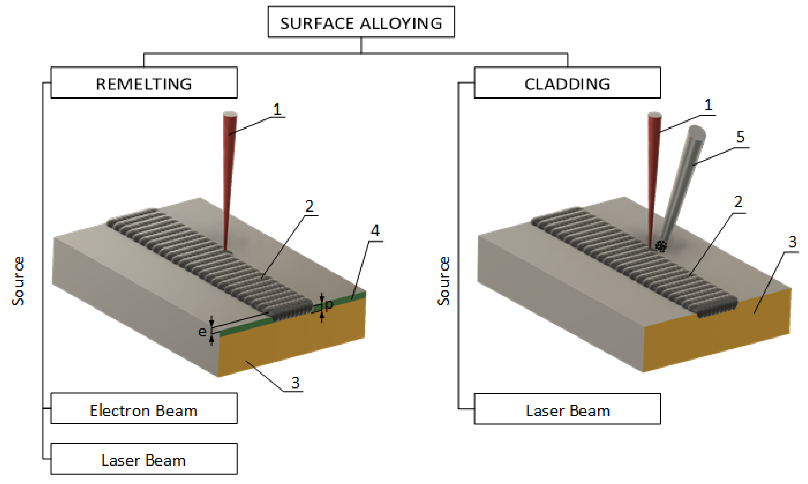
There are two types of surface alloying (LSA): remelting and cladding. Figure 1 shows the essential difference for them.
Remelting. An alloying process, which is taking place with the use of the previously applied thin layer (through thermal spraying or electrolytically) on the substrate in a sealed form (film, coating) or porous (powder paste) and then remelted using a source of energy laser or electron beam [16]. The melting material partially or entirely dissolves in the matrix. After solidifying the mixture, the layer’s structure and chemical composition are different compared to the processed substrate. It is possible to achieve texture (periodic) structures on the melted surface using the modulated energy source [17].
Cladding. A process involving the melting of a mechanically applied coating or injecting co-axially or off-axially with the energy source particle of material in the form of powder, wire or gas. The laser beam energy is absorbed both by the powder and the base material, which allows the simultaneous melting of both materials [18]. Using this method, partial or complete dissolution of the alloying material may also occur in the substrate. The material feeding method to the energy source is essential in the alloying process. The design of the nozzle significantly influences the degree of oxidation of the alloying material. There are three main concepts [18,19,20]:
- Off-axial powder injection;
- Continuous co-axial powder injection (a powder gas stream cone is produced which encloses the laser beam);
- Discontinuous co-axial powder injection (three or more powder gas streams are fed co-axial to the laser beam).
- The most important physical phenomena within cladding, as a type of LSA, are:
- Reflection and absorption of the laser beam;
- Heat conditions;
- Melt pool dynamic; and
- Rapid solidification.
The melt pool dynamics are essential for surface alloying due to the short life (seconds). The alloying material cannot be homogeneously distributed by diffusion phenomena only. The melt pool’s flow velocity, which is orders of magnitude greater than the scan velocity during laser-alloying, ensures sufficient mixing [13].
The following approaches within the cladding could be described: single layer, multiple layers, composite layer, or graded layer. Due to their insufficient wear resistance for potential applications, aluminum, magnesium, and titanium are the most popular materials for the surface alloying process. For example, titanium alloys (e.g., TiAl6V2) are usually alloyed using only gas nitrogen (N2) due to a high titanium affinity for nitrogen. Pure TiN has a hardness of 2500 HV [21]. Therefore, LSA with nitrogen is an effective method to improve titanium alloys’ hardness and wear resistance [22]. Alloys like Nitinol (NiTi) can also be laser gas nitrided to obtain an airtight and corrosion-resistant coating [23]. Surface alloying of aluminum-based alloys like AlSi10Mg with nickel results in aluminum-rich intermetallic phases Al3Ni, which hast higher hardness due to a complex crystal structure. The surface-alloyed zone has a hardness around 300 HV0.3 in compare with the hardness of base material, which is approximately 60 HV0.3 [13,24]. Additionally, aluminum alloys are hardened using silicon, carbon or nitrogen elements [25]. Cast iron, steel, and iron-based alloys are surface alloyed with chromium, molybdenum, boron, or nickel to improve hardness, wear/corrosion resistance [7,11,12,13]
Stellite 6 belongs to the cobalt alloys of the CoCrW system; for these alloys, there are three possible strengthening mechanisms: solution, secondary, and grain refinement [26]. In most cases, the dominant mechanism is the solution hardening mechanism, in which participate alloying elements such as chromium (Cr), molybdenum (Mo), tungsten (W), niobium (Nb), and tantalum (Ta) [27].
According to the Co-Cr-Re phase diagram [28], rhenium has a high solubility in cobalt and influences the temperature of phase transformation in Co-Cr alloys. As a result, its addition improves cobalt-based alloys’ functional properties and expands the range of working temperature of chosen material [28].
There are several reasons for the potential use of rhenium as a modifier of cobalt-based alloys’ properties. Some of them based on [29] are listed below:
- (a)
- According to the phase equilibrium diagram [30], rhenium has a high solubility in cobalt (the base element). Hence, its operation as a modifier may lead to an increase of strength properties as a result of solution strengthening;
- (b)
- rhenium, like chromium and molybdenum, increases the temperature of the cobalt allotropic transformation, thus contributing to the formation of a multi-phase structure that influences the functional properties of cobalt-based alloys; and
- (c)
- as the proportion of rhenium powder increases, the efficiency of dissolving its particles in the liquid metal increases. However, the number of residual, undissolved particles in the solidified matrix increases.
Undissolved rhenium particles can have a negative effect on local electrochemical (due to the difference in electrode potentials) and high-temperature corrosion in an oxygen-containing environment. Additionally, rhenium is often used to alloy superalloys to increase strength under extreme operating conditions, including resistance to fatigue at elevated temperatures [31]. Researchers [32,33,34] also indicate a positive effect of rhenium on increasing corrosion resistance and wear resistance, including titanium alloys.
Usually, Stellite 6 are used for the LSA of steel (316L [35], AISI 1016L [36]), aluminum alloys (Al5Mg [37]), and Ni-based alloys [38]. However, it could be the subject of alloying as well. The main challenge with Stellite 6 alloy is a fabrication and finishing the surface with traditional methods. Therefore, the efforts to investigate the manufacturing possibilities [8] and the possibility of surface modification are still in great interests among researchers.
This work aimed to modify the Stellite 6 surface layer using an LDF diode laser (4000 W). During this process, a rhenium powder was introduced onto the surface of the Co-based alloy. The possibility of improving tribological and corrosion wear properties are interesting and worth investigating.
2. Materials and Methods
2.1. Materials
Cobalt-based alloy Stellite 6 was used as a substrate in an experiment. For laser surface alloying (LSA), a commercially pure rhenium powder (99.9 wt% Re; 0.25 at% O and 0.020 at% H) was introduced onto the surface of the Stellite 6. Rhenium powder underwent a plasma-atomization process to obtain spheroidal particles. For the experiment, the fraction of Re particles ≤ 40 μm were separated by sieving using a Fritsch Analysette 3 (Idar-Oberstein, Germany) vibrating sieve with a set of sieves according to ISO 3310 -1 standard.
The chemical composition of Stellite 6 is presented in Table 1.
2.2. Laser Surface Alloying
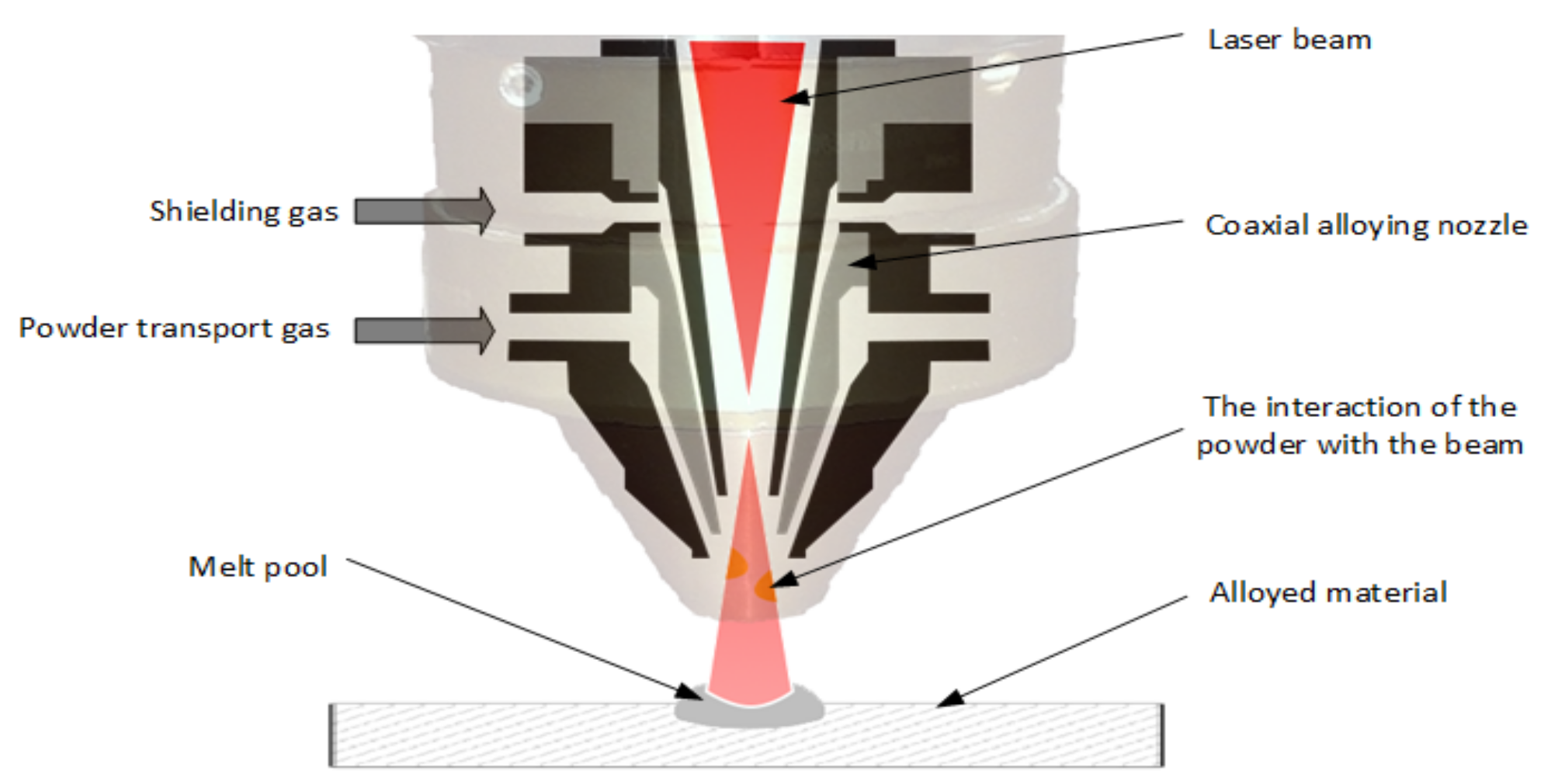
The surface of the cobalt-based alloy (Stellite 6) was laser alloyed with rhenium powder using an LDF 4000-30 diode laser (Table 2) with continuous co-axial powder processing head COAX8 powerline series from Fraunhofer IWS (Dresden, Germany) (Figure 2). The following operating parameters were chosen for change: power, preliminary heating of base material, and powder feed speed (Table 2).
The parameters of the alloying process were verified in two stages.
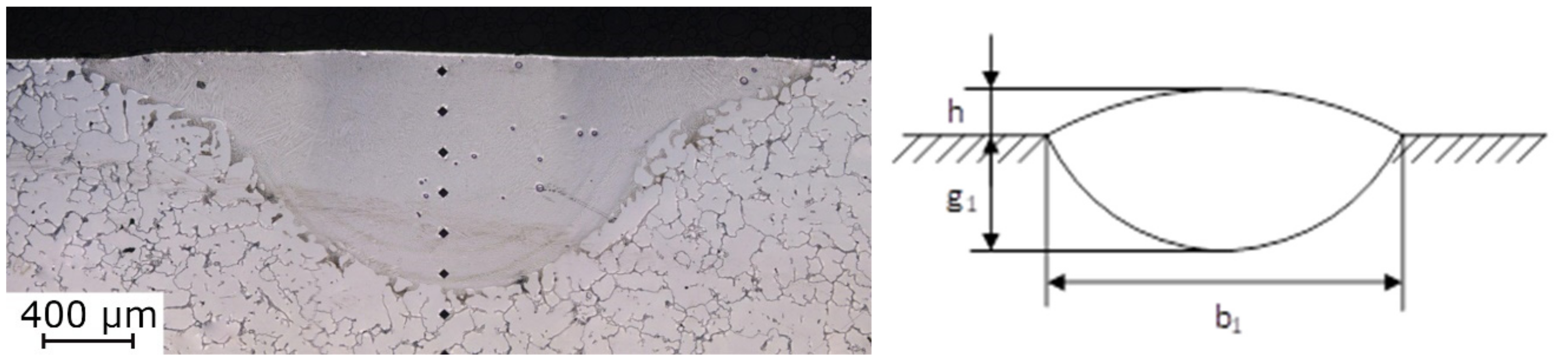
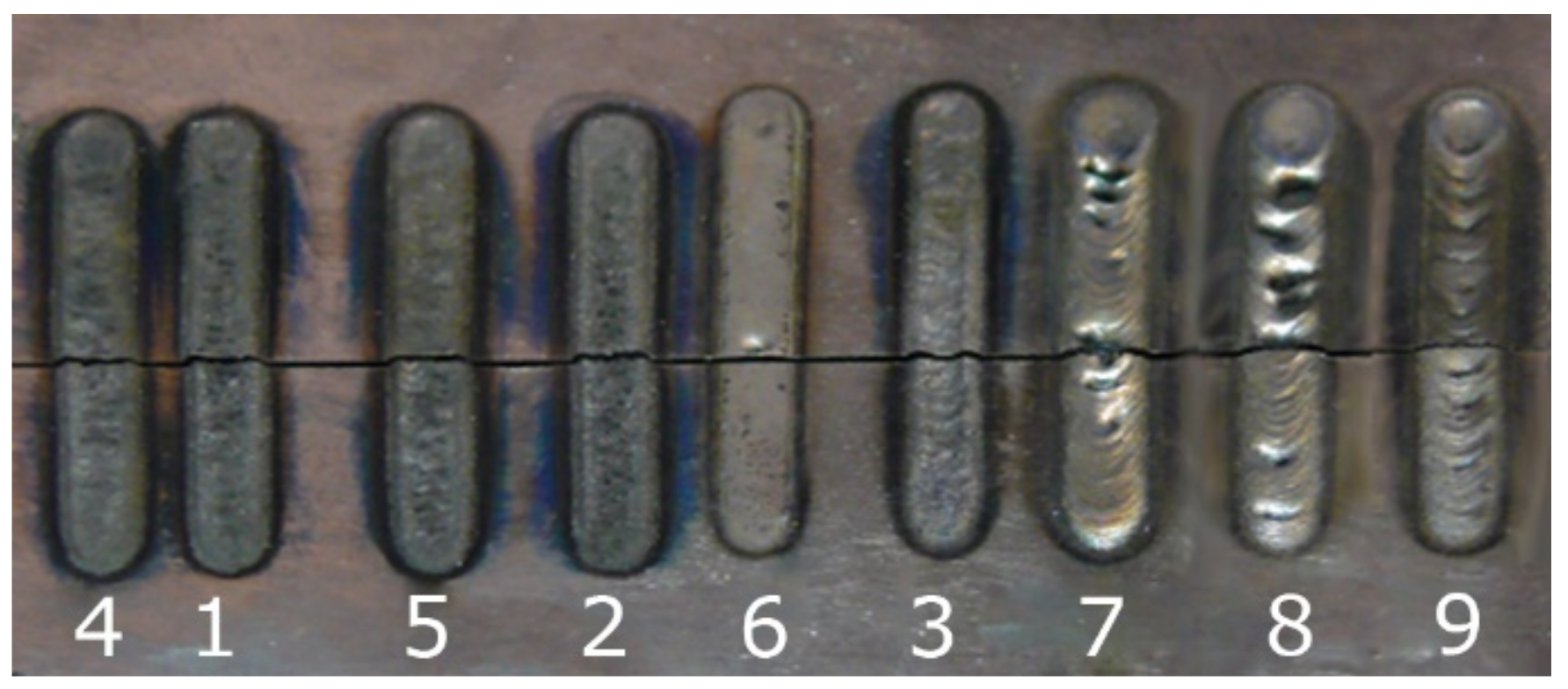
In the first stage, nine variants of single stitches were made, assuming the powder feeding speed (1.92, 2.87, and 3.83 g/min) and the laser power (700, 900, and 1300 W) as a variable with a constant nozzle feed rate of 600 mm/min. The evaluation of the geometrical features (Figure 3) of the obtained stitches was made on the cross-sections. The evaluation is based on the measurements of:
- Penetration width and depth (b1 and g1);
- laser surface alloying height relative to the substrate surface (h); and
- HAZ width, depth and reach.
Hardness profiles HV0.3 were determined for each stitch to compare the effectiveness of the rhenium fusion.
Within the second stage, taking into account the previous results, the surface-alloyed layers were performed. Therefore, within the second stage, the following parameters were chosen as variables: powder feed speed, laser power, and the distance between the stitches (overlap width). Evaluation of the obtained effects included:
- The degree of porosity of the alloy layers and their thickness;
- rhenium fusion efficiency measured by the repeatability of properties; and
- hardness profiles (Vickers method with a load of 2.94 N/HV0.3).
2.3. Microstructure
The microstructure analysis of samples within both stages was performed on cross-sections of the laser-tracks etched with 87 Glyceregia (normalized according to ASTM E 407) consisting of 15 mL HCl, 10 mL glycerol, and 5 mL HNO3. The etching was performed with a fresh reagent, 5–15 min after preparation.
OM and SEM incorporating energy dispersive X-ray analysis (EDX) were used to characterize the microstructure and chemical composition of surface layers structures. SEM images were obtained using an EVO MA25 microscope (Carl Zeiss AG, Germany).
The geometry of the laser tracks was measured using the Olympus LEXT OLS4000 confocal microscope (Tokyo, Japan).
2.4. Properties Evaluation
Corrosion resistance tests (electrochemical analysis) and an abrasive wear resistance analysis were performed to evaluate surface-alloyed layers’ functional properties.
2.4.1. Abrasion Resistance
A three-body abrasion test was performed following the GOST 23.208-79 standard (similar to ASTM G65-04) to determine the abrasion resistance. The measurements were made using a “rubber wheel” device compliant with the GOST standard mentioned above. The abrasive used in the friction node was aluminum oxide, 90–240 µm in size. The device’ measured parameters are the following: rubber-clad steel wheel with a diameter of 50 and 15 mm thick, load 45 N and rotating speed 60 rpm.
The measured value was the samples’ weight loss compared to the reference sample following the GOST 23.208-79 standard. The reference sample was made of C45 standardized steel (EN 10083-2) with a 200 HV10. The measure of abrasion resistance under these conditions is the abrasion index:
where:
Mref and M—loss in weight of the reference steel specimen and the examined specimen;
ρref and ρ—density values of the reference steel specimen and the examined specimen; and
Nref and N—total number of wheel rotations during the tests of the reference (steel C45) specimen and the examined specimen (Nref = 600; N = 600 or 1800 depending on the hardness of the examined specimen).
2.4.2. Electrochemical Analysis
The electrochemical analysis assessed corrosion resistance, taking into account two main criteria: measuring the corrosion potential and providing a pitting corrosion test. As a result of the work carried out, the Tafel and cyclic curves of polarization were determined. The tests were carried out on the reference material Stellite 6 (CoCrW) and in the selected variant of the alloy addition Re (V11). Electrochemical measurements were performed at ambient temperature using 400 mL of 3 wt% NaCl solution. Potentiodynamic polarization curves were determined using a three-electrode cell assembly consisting of (1) the test sample as the working electrode, (2) SS316 stainless steel as the counter electrode, and (3) an Ag/AgCl electrode in a Haber–Luggin capillary as the reference electrode. The surface area of the polarized sample was 0.762 cm2. The electrochemical measurements were performed with the use of a PGSTAT 320 N potentiostat (Metrohm Autolab B.V., The Netherlands). Preparation of the test cycle’s surface included grinding with 1000 grit sandpaper and ultrasonic cleaning of the surface with acetone. The open-circuit potential (OCP) was monitored for 30 min after immersing the test solution samples. The polarization curves in the Tafel range for the CoCrW reference and the selected Re-alloyed variant were obtained by polarizing them with a voltage scan rate of 1 mV/s in the range from −150 mV with OCP to +150 mV with OCP. Shortly after the Tafel measurements, the cyclic polarization measurements were extended. Potential scanning was started at 100 mV below the OCP and reversed below 2 V.
3. Results and Discussion
3.1. Selection of Process Parameters
Nine single laser-tracks of rhenium alloying (Figure 4) were performed for nine different laser power and powder feed rate variants. Images and measurements of selected cross-sections of the single laser-tracks, as marked in Figure 4, are summarized in Table 3 and Table 4.
Visual analysis and the results of geometric measurements showed that all the single laser-tracks turned out to be unsatisfactory due to: (1) high porosity and microcrack formation in the alloyed layer, (2) low efficiency of dissolving rhenium particles in the substrate. For single laser-tracks, the laser power higher than 900 W results in an increase of the open cavities’ number within the alloyed surface with higher porosity and deformation. The best geometric effect was obtained using 900 W power.
Based on the obtained results and the fact that Stellite 6 has a high tendency to the cracks and porosity, due to cobalt’s high thermal conductivity, additional LSA tests with rhenium were carried out using a preheated substrate to the temperature of 200 °C.
The cross-sections of single laser-tracks made with a constant laser power of 900 W and nozzle feed rate of 600 mm/min for three variants of the powder feeding speed presented in Table 5, their geometric dimensions presented in Table 6.
The structure of cross-sections of the single laser-tracks presented in Table 5 indicates that heating of the substrate allowed to minimize the tracks’ porosity, increased the fusion efficiency of rhenium powder and improved the laser track geometry reducing the fusion face height.
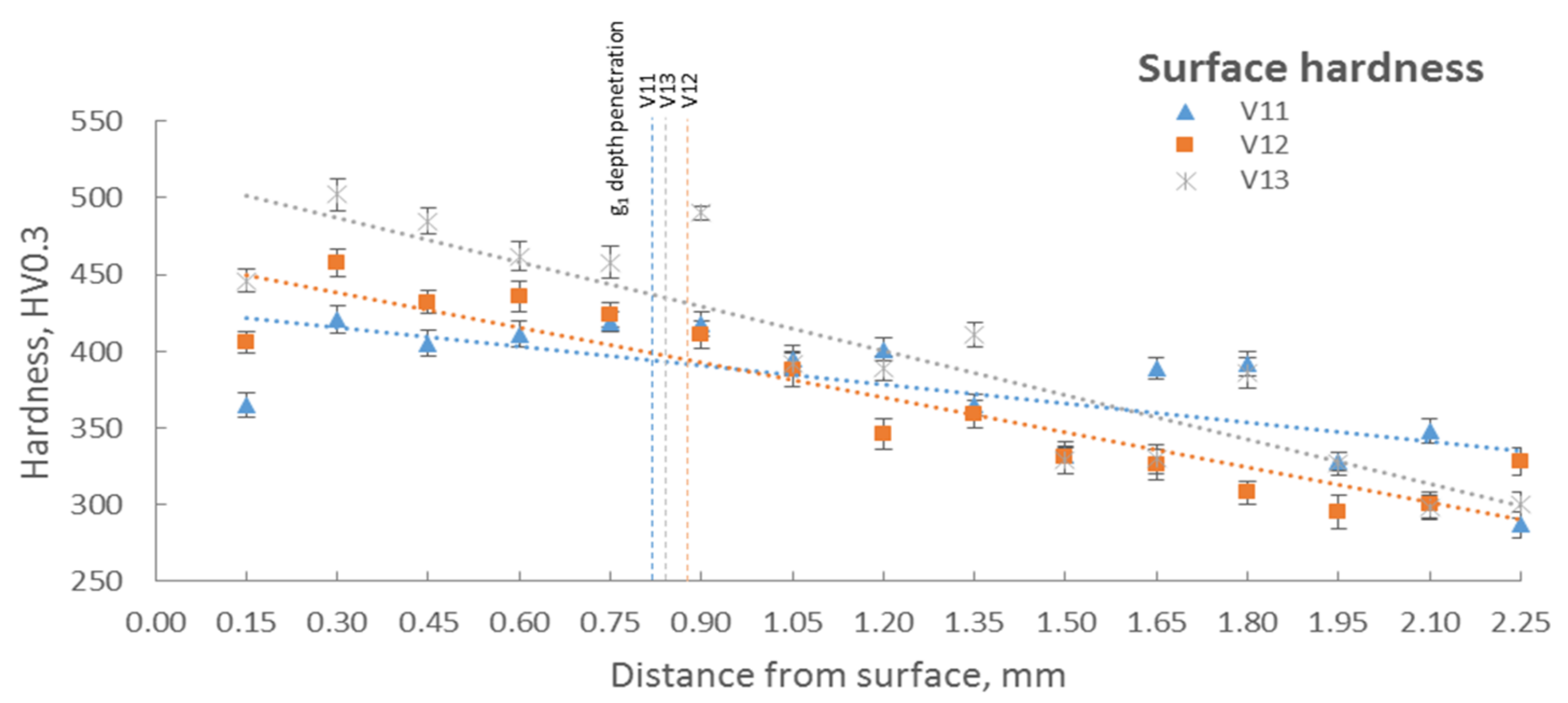
The hardness of three samples (V11, V12, and V13) was analyzed (Figure 5), with an increase of hardness in comparison with the substrate by 35% (500 HV0.3 for the alloyed layer (V13) to 300–330 HV0.3 (substrate)).
Due to the moderate increase in the single laser tracks hardness (Figure 5) made when the substrate was preheated and the relatively low amount of undissolved rhenium particles, a control EDS analysis of the dissolved rhenium content in the substrate was carried out. The areas between the rhenium particles were analyzed (Table 7). As can be seen, in the case of sample V11 (powder feed rate: 1.92 g/min), the rhenium content in the surface layer is about 14–16 wt%. Re. In case of a higher powder feed rate, of approx. 3 g/min (samples V12 and V13), the Re content is a maximum of 30 wt%.
The parameters for samples V11 and V12 were taken into account for samples’ surface-alloying within the second stage. Due to the high level of porosity on the cross-section in a single laser-track V13, that variant was discarded.
Based on the first stage results, LSA was done as follows: 20 laser-tracks on 150 × 150 mm substrates with an overlap equal to 50% of the beam spot diameter (2.5 mm). The process parameters, the values of the selected penetration depth and the usable thickness of the prepared layer variants are given in Table 8. The images of the cross-sections of the prepared layers are shown in Table 9. The modified surface’s geometry characteristics (depth, homogeneity, width, and roughness) were measured using confocal laser microscopy.
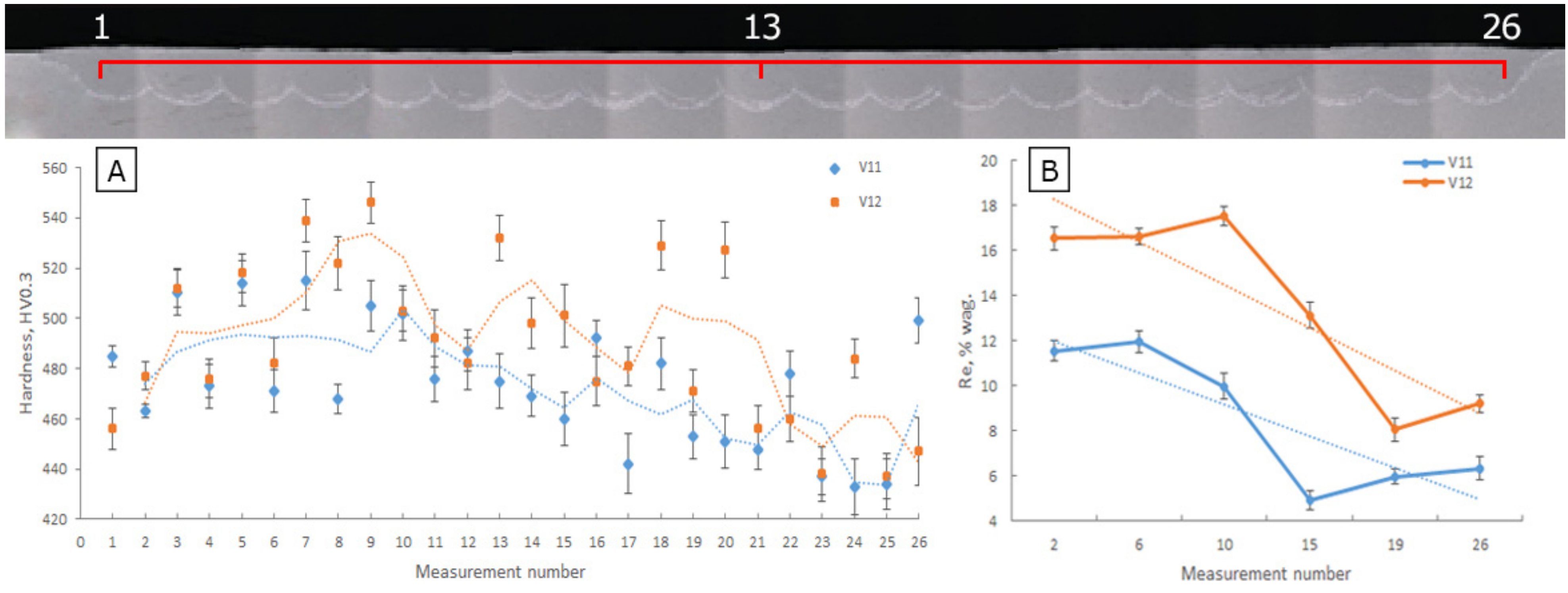
The hardness and analysis of rhenium concentration within alloyed layers were examined to verify the selected parameters. The results of the measurements are presented in Figure 6A,B. The local porosity for the V12 surface structure was observed similarly to the already rejected variant V13. Repeated attempts gave similar results. Low powder flow at high and moderate powder feed values causes unstable operation of the powder feeder and, consequently, leads to the powder feed’s temporary interruption. The occurrence mentioned above increases the amount of energy supplied to the substrate and disturbs the padding process, causing local material evaporation.
The LSA upper layer’s average hardness was 450–500 HV0.3 compared with the substrate’ hardness—300–330 HV0.3 (the relative growth of hardness is 50–60%).
3.2. Microstructure and Elemental Composition
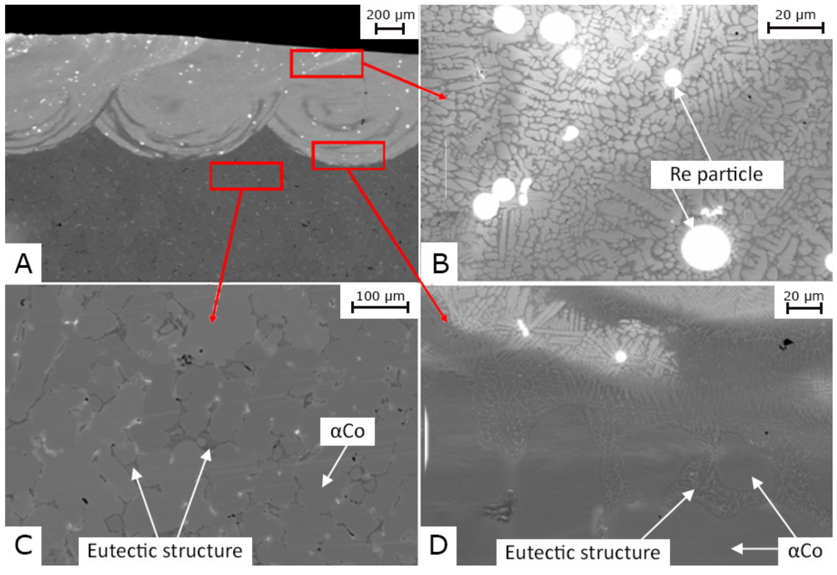
The microstructure (Figure 7) was investigated with scanning electron microscopy (SEM). The elemental composition of the modified surface zone was evaluated using dispersive energy analysis (EDS).
The microstructure of the substrate (Stellite 6) mainly consisted of a Co-rich matrix and eutectic structures. According to the Co-Cr-W diagram [39], the dominant phase is α with αCo composition (fcc).
The microstructure of laser-alloyed area (upper layer) consists of the ultrafine structure of dendrites of Co-rich γ solid solution (fcc), as well as the dispersion of eutectic (mainly consisted of γ-Co with the carbides of M7C3 (hcp)) in the laser alloyed zone and single particles of not fully dissolved rhenium (Figure 7B). The carbides situated alongside grain boundaries cause a significant effect of dispersion strengthening, and the addition of rhenium results in a significant increase of surface hardness. The effect of the hardness increase of a layer of 50–60% should be attributed to the strong fragmentation of dendrites γ solid solution (austenite cobalt), and laser surfaced alloying with rhenium. According to [8], the refinement of the microstructure and eutectic itself results in an increase of hardness by about 17–20% compared with the substrate (Stellite 6) manufactured conventionally.
The difference in the microstructure of the laser alloyed surface and substrate shown in Figure 7B,C. The Co-rich eutectic dendrites in the upper layer, which underwent laser surfaced alloyed modification, are significantly finer than Co-rich eutectic in the substrate. The refinement of the microstructure and particularly the Co-rich eutectic appeared due to the high-speed cooling, which is typical for laser-based processes.
3.3. Three-Body Abrasion Test
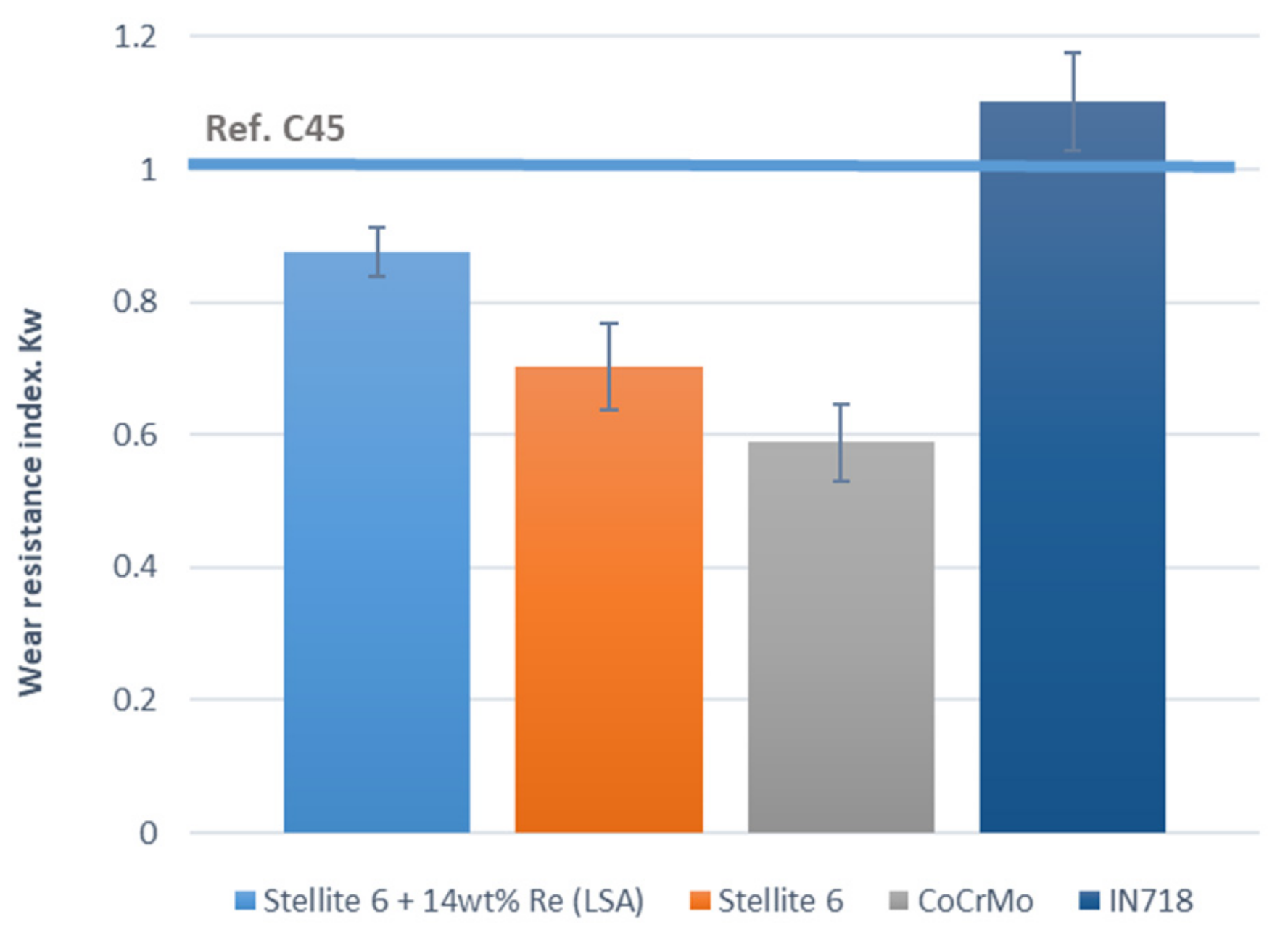
It was found that rhenium content in the samples for the wear resistance analysis is about 14–16 wt%, and the density of the alloyed surface is 9 g/cm3. The LSA upper layer’s average density was calculated using the law of mixtures, taking into account the rhenium content. The micro-areas, free of undissolved rhenium powder particles, were analyzed. The test results are presented by wear resistance index Kw (Table 10 and Figure 8).
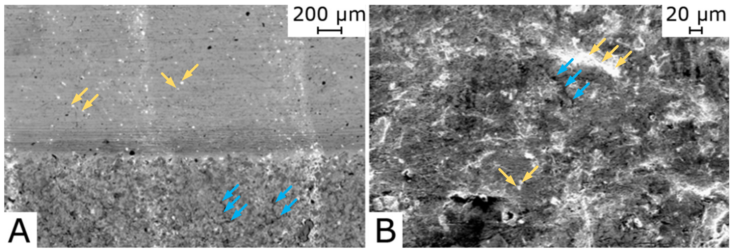
The changes on the surface were observed with SEM (Figure 9). The yellow-arrows indicate the undissolved particles of rhenium, and blue-arrows indicate the cracks on the surface caused by the three-body abrasion test.
The laser alloying by rhenium shows a slight increase in wear resistance index (Kw ≈ 0.88), which is higher than Kw of the unmodified substrate (Stellite 6). It is distinguishingly higher than a wear-resistant index of CoCrMo alloy manufactured in SLM technology (Kw ≈ 0.59). However, according to [41], the wear intensity determined withing the pin-disc type test in the comparable test conditions will be 10 times greater than the intensity determined on the rubber wheel device (three-body abrasive test). The reason is the forced setting of the abrasive grains in the sandpaper, which results in cutting under the test conditions.
3.4. Electrochemical Measurements
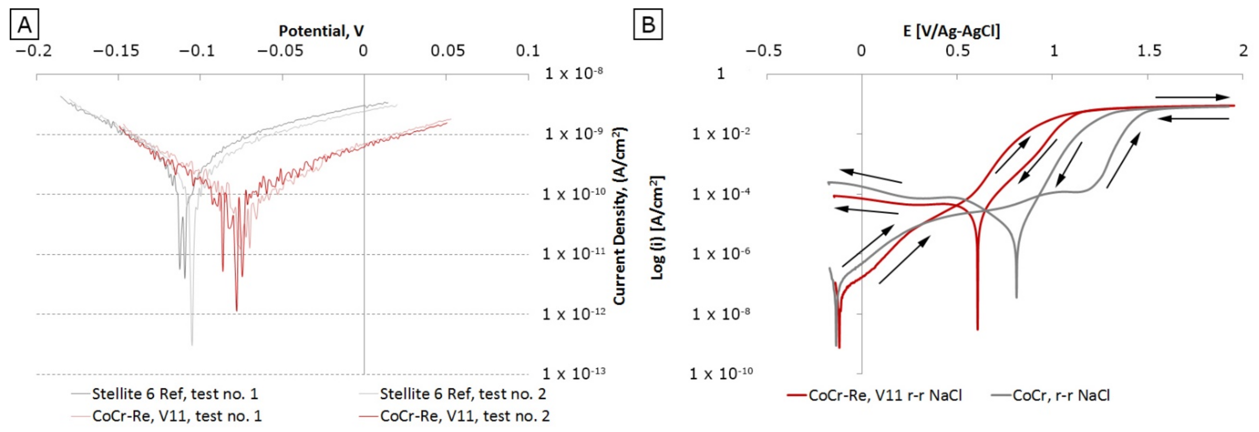
The corrosion potential of a laser-alloyed surface is better than for a substrate due to a positive influence of rhenium on the corrosion resistance of the Stellite 6 in 3% NaCl solution. Analysis of the resistance to pitting corrosion in the same solution indicates that alloying by rhenium stabilizes the surface and anticipates pits’ formation on the surface (Figure 10). Samples processed for electrochemical analysis content about 14–16 wt% of rhenium (V11) according to the EDS analysis.
The corrosion potential of the alloyed layers with Re on the Stellite 6 substrate is higher than the substrate’s corrosion potential (Figure 10A), and the corrosion current density is lower (ikor of the substrate is 0.77 × 10⁻⁷ A/cm2 and ikor of Stellite 6 modified with rhenium is 0.17 × 10⁻⁷ A/cm2). This means there is a significant positive effect with the addition of rhenium on the corrosion resistance in a salt solution environment.
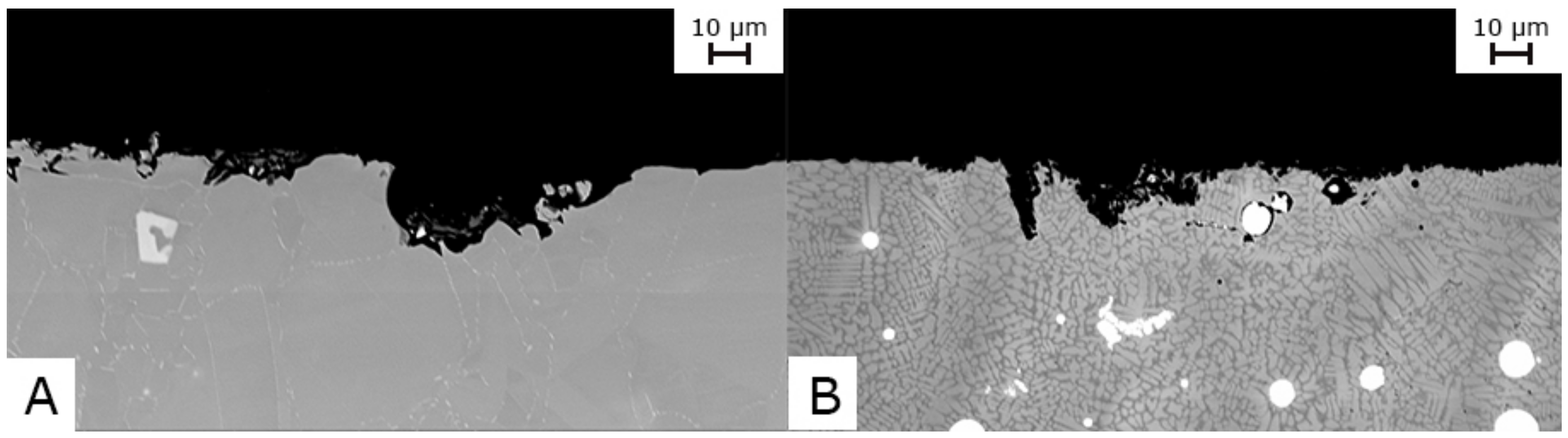
The alloying surface with rhenium (Figure 10B) significantly narrowed the loop and shifted it to lower potentials while shifting the return scanning curves towards lower current density values, which proves a particular reduction in the alloy resistance to pitting corrosion (Figure 11), but a high ability to their repassivation.
4. Conclusions
The selected process parameters (the laser power of 900 W, powder feed rate in the range 1.92–3.83 g/min, and necessarily preheating of the substrate up to 200 °C) allow to obtain laser surface-alloyed layers on the Stellite 6 substrate.
Their thickness is at least 600 µm, with 11–17%wt of rhenium concentration in the layers. The microstructure of laser alloyed surface layers is consists of the ultrafine structure of dendrites of γ solid solution (cobalt austenite) with a hardness of 450–500 HV0.3.
Surface alloying with rhenium results in a significant increase in surface hardness. The effect of the hardness increase of a layer of 50–60% should be attributed to the strong fragmentation of dendrites γ solid solution (austenite cobalt), and laser surfaced alloying with rhenium.
The laser alloying by rhenium shows a slight increase of wear resistance index (Kw ≈ 0.88), similar to a laser modified surface with high-carbon Stellite 6.
The corrosion potential of a laser-alloyed surface is better than the corrosion potential of Stellite 6 substrate, including reducing resistance to pitting corrosion with high ability to their repassivation.
Laser surface alloying (LSA) is an attractive technique for repairing and improving functional materials’ wear properties. Repairing or modifying the surface layer with additional elements, such as rhenium, could be beneficial, especially in improving functional properties (wear and corrosion resistance). However, in the case of Stellite 6, the addition of rhenium did not bring spectacular results compared to the total costs of using rhenium for such a purpose.
Author Contributions
Conceptualization: I.S. and K.K.; methodology: I.S. and K.K.; formal analysis: I.S. and K.K.; investigation: I.S. and K.K.; writing—original draft preparation: I.S. and K.K.; writing—review and editing: I.S. and K.K.; visualization: K.K. All authors have read and agreed to the published version of the manuscript.
Funding
This research was funded by the Polish National Centre for Research and Development, grant number PBS1/A5/12/2012.
Institutional Review Board Statement
Not applicable.
Informed Consent Statement
Not applicable.
Acknowledgments
In this section, you can acknowledge any support given which is not covered by the author contribution or funding sections. This may include administrative and technical support, or donations in kind (e.g., materials used for experiments).
Conflicts of Interest
The authors declare no conflict of interest.
References
- Hasan, M.S.; Mazid, A.M.; Clegg, R. The Basics of Stellites in Machining Perspective. Int. J. Eng. Mater. Manuf. 2016, 1. [Google Scholar] [CrossRef]
- Ruml, Z.; Straka, F. A new model for steam turbine blade materials erosion. Wear 1995, 186–187, 421–424. [Google Scholar] [CrossRef]
- Codaro, E.N.; Melnikov, P.; Ramires, I.; Guastaldi, A.C. Corrosion behavior of a cobaltchromium-molybdenum alloy. Russ. J. Electrochem. 2000, 36. [Google Scholar] [CrossRef]
- Yao, M.X.; Wu, J.B.C.; Xu, W.; Liu, R. Metallographic study and wear resistance of a high-C wrought Co-based alloy Stellite 706K. Mater. Sci. Eng. A 2005, 407, 291–298. [Google Scholar] [CrossRef]
- Sims, C.T. A contemporary view of cobalt-base alloys. JOM 1969, 21. [Google Scholar] [CrossRef]
- Picas, J.A.; Punset, M.; Teresa Baile, M.; Martín, E.; Forn, A. Properties of WC-CoCr based coatings deposited by different HVOF thermal spray processes. Plasma Process. Polym. 2009, 6. [Google Scholar] [CrossRef]
- Zhao, C.; Tian, F.; Peng, H.-R.; Hou, J.-Y. Non-transferred arc plasma cladding of Stellite Ni60 alloy on steel. Surf. Coatings Technol. 2002, 155, S0257–S8972. [Google Scholar] [CrossRef]
- Li, Z.; Cui, Y.; Wang, J.; Liu, C.; Wang, J.; Xu, T.; Lu, T.; Zhang, H.; Lu, J.; Ma, S.; et al. Characterization of Microstructure and Mechanical Properties of Stellite 6 Part Fabricated by Wire Arc Additive Manufacturing. Metals 2019, 9, 474. [Google Scholar] [CrossRef] [Green Version]
- Liu, R.; Wu, X.J.; Kapoor, S.; Yao, M.X.; Collier, R. Effects of Temperature on the Hardness and Wear Resistance of High-Tungsten Stellite Alloys. Metall. Mater. Trans. A Phys. Metall. Mater. Sci. 2015, 46, 587–599. [Google Scholar] [CrossRef]
- Berthod, P. High-Temperature Extreme Alloys. In Reference Module in Materials Science and Materials Engineering; Elsevier: Amsterdam, The Netherlands, 2020. [Google Scholar]
- Yan, Y.; Neville, A.; Dowson, D. Tribo-corrosion properties of cobalt-based medical implant alloys in simulated biological environments. Wear 2007, 263, 1105–1111. [Google Scholar] [CrossRef]
- Trejo, J.; Tolosa, R.; Ruiz, N.; Ninin, P.; Fuenmayor, C.; Zambrano, M.; Palma, O.; Nuñez, Y. Comparative study of the main properties associated with thin layers of coatings with the cobalt-chromium-tungsten alloy (stellite) and hard chromium plating used as reinforcements for wood sawing. Mech. Mater. 2021, 152. [Google Scholar] [CrossRef]
- Wissenbach, K. Surface Treatment. In Tailored Light 2; Springer: Berlin/Heidelberg, Germany, 2011; pp. 173–239. [Google Scholar]
- Kosolapova, T. Properties, Production and use of Refractory Compounds: A Reference Book; Metallurgia: Novosibirsk, Russia, 1986. (in Russian) [Google Scholar]
- Burakowski, T.; Wierzchoń, T. Metal Surface Engineering; WNT: Warszawa, Poland, 1995. (In Polish) [Google Scholar]
- Chen, X.C.; Xie, J.W.; Fox, P. Direct laser remelting of iron with addition of boron. Mater. Sci. Technol. 2004, 20, 715–719. [Google Scholar] [CrossRef]
- Xin, B.; Ren, J.; Wang, X.; Zhu, L.; Gong, Y. Effect of Laser Remelting on Cladding Layer of Inconel 718 Superalloy Formed by Laser Metal Deposition. Materials 2020, 13, 4927. [Google Scholar] [CrossRef]
- De Oliveira, U.; Ocelík, V.; De Hosson, J.T.M. Analysis of coaxial laser cladding processing conditions. Surf. Coatings Technol. 2005, 197, 127–136. [Google Scholar] [CrossRef]
- Ya, W.; Hernández-Sánchez, J.F.; Pathiraj, B.; Veld, A.J.H.I.t. A study on attenuation of a Nd:YAG laser power by co-axial and off-axial nozzle powder stream during cladding. In Proceedings of the ICALEO 2013—32nd International Congress on Applications of Lasers and Electro-Optics; Laser Institute of America: Orlando, FL, USA, 2013; Volume 2013, pp. 453–462. [Google Scholar]
- Wu, J.; Zhao, P.; Wei, H.; Lin, Q.; Zhang, Y. Development of powder distribution model of discontinuous coaxial powder stream in laser direct metal deposition. Powder Technol. 2018, 340, 449–458. [Google Scholar] [CrossRef]
- Folkes, J.; West, D.R.F.; Steen, W.M. Laser Surface Melting and Alloying of Titanium. In Laser Surface Treatment of Metals; Springer Netherlands: Dordrecht, The Netherlands, 1986; pp. 451–459. [Google Scholar]
- Abboud, J.H.; West, D.R.F. Laser surface alloying of titanium with aluminium. J. Mater. Sci. Lett. 1990, 9, 308–310. [Google Scholar] [CrossRef]
- Man, H.C.; Cui, Z.D.; Yue, T.M. Surface characteristics and corrosion behavior of laser surface nitrided NiTi shape memory alloy for biomedical applications. J. Laser Appl. 2002, 14, 242–247. [Google Scholar] [CrossRef]
- D’Amato, C.; Betts, J.C.; Buhagiar, J. Laser surface alloying of an A356 aluminium alloy using nickel and Ni-Ti-C: A corrosion study. Surf. Coatings Technol. 2014, 244, 194–202. [Google Scholar] [CrossRef]
- Walker, A.; West, D.R.F.; Steen, W.M. Laser surface alloying ferrous materials with carbon. In Proceedings of the Laser’83 Optoelectronik conference; Springer: Berlin/Heidelberg, Germany, 1983; pp. 322–326. [Google Scholar]
- Liu, R.; Xi, S.Q.; Kapoor, S.; Wu, X.J. Investigation of solidification behavior and associate microstructures of Co-Cr-W and Co-Cr-Mo alloy systems using DSC technique. J. Mater. Sci. 2010, 45, 6225–6234. [Google Scholar] [CrossRef]
- ASM Handbook, Volume 02: Properties & Selection: Nonferrous Alloys and Special-Purpose Materials by ASM International—Reviews, Discussion, Bookclubs, Lists. Available online: http://www.goodreads.com/book/show/2121408.ASM_Handbook_Volume_02 (accessed on 16 February 2016).
- Depka, T.; Somsen, C.; Eggeler, G.; Mukherji, D.; Rösler, J. Sigma phase evolution in Co–Re–Cr-based alloys at 1100 °C. Intermetallics 2014, 48, 54–61. [Google Scholar] [CrossRef]
- Smolina, I. Selective Laser Melting (SLM) for Processing CoCrMo Alloy Modified with Rhenium; Politechnika Wrocławska: Wrocław, Poland, 2017. (in Polish) [Google Scholar]
- Brunner, M.; Hüttner, R.; Bölitz, M.-C.; Völkl, R.; Mukherji, D.; Rösler, J.; Depka, T.; Somsen, C.; Eggeler, G.; Glatzel, U. Creep properties beyond 1100 °C and microstructure of Co–Re–Cr alloys. Mater. Sci. Eng. A 2010, 528, 650–656. [Google Scholar] [CrossRef]
- Brynk, T.; Pakiela, Z.; Ludwichowska, K.; Romelczyk, B.; Molak, R.M.; Plocinska, M.; Kurzac, J.; Kurzynowski, T.; Chlebus, E. Fatigue crack growth rate and tensile strength of Re modified Inconel 718 produced by means of selective laser melting. Mater. Sci. Eng. A 2017, 698, 289–301. [Google Scholar] [CrossRef]
- Majchrowicz, K.; Pakieła, Z.; Brynk, T.; Romelczyk-Baishya, B.; Płocińska, M.; Kurzynowski, T.; Chlebus, E. Microstructure and mechanical properties of Ti–Re alloys manufactured by selective laser melting. Mater. Sci. Eng. A 2019, 765, 138290. [Google Scholar] [CrossRef]
- Majchrowicz, K.; Pakieła, Z.; Moszczyńska, D.; Kurzynowski, T.; Chlebus, E. Hot Corrosion of Ti–Re Alloys Fabricated by Selective Laser Melting. Oxid. Met. 2018, 90, 83–96. [Google Scholar] [CrossRef] [Green Version]
- Chlebus, E.; Kuźnicka, B.; Dziedzic, R.; Kurzynowski, T. Titanium alloyed with rhenium by selective laser melting. Mater. Sci. Eng. A 2015, 620, 155–163. [Google Scholar] [CrossRef]
- Mikołajczak, D.; Kulka, M.; Makuch, N.; Dziarski, P. Laser alloying of 316L steel with boron and Stellite-6. Inżynieria Mater. 2017, 6, 259–265. [Google Scholar] [CrossRef]
- Mazumder, J.; Singh, J. Laser Surface Alloying and Cladding for Corrosion and Wear. High Temp. Mater. Process. 1986, 7, 101–106. [Google Scholar] [CrossRef]
- Pakieła, W.; Tanski, T.; Brytan, Z.; Chladek, G.; Pakieła, K. The impact of laser surface treatment on the microstructure, wear resistance and hardness of the AlMg5 aluminum alloy. Appl. Phys. A Mater. Sci. Process. 2020, 126, 231. [Google Scholar] [CrossRef] [Green Version]
- Wang, K.; Chang, B.; Lei, Y.; Fu, H.; Lin, Y. Effect of Cobalt on Microstructure and Wear Resistance of Ni-Based Alloy Coating Fabricated by Laser Cladding. Metals 2017, 7, 551. [Google Scholar] [CrossRef] [Green Version]
- Gupta, K.P. The Co−Cr−W (Cobalt-Chromium-Tungsten) system. J. Phase Equilibria Diffus. 2006, 27, 178–183. [Google Scholar] [CrossRef]
- Kurzynowski, T.; Smolina, I.; Kobiela, K.; Kuźnicka, B.; Chlebus, E. Wear and corrosion behaviour of Inconel 718 laser surface alloyed with rhenium. Mater. Des. 2017, 132. [Google Scholar] [CrossRef]
- Hejwowski, T. Modern Heat Applied Coatings Resistant to Abrasive and Erosive Wear; Biblioteka Cyfrowa Politechniki Lubelskiej: Lublin, Poland, 2013; ISBN 978-83-63569-56-3. [Google Scholar]
Figure 1.
Overview of the two main methods of surface modification remelting and cladding: (1) energy source; (2) alloying zone; (3) substrate; (4) coating of the stop material (typical e/p ratio is 0.05–0.1); (5) solid particles or alloying gas.
Figure 1.
Overview of the two main methods of surface modification remelting and cladding: (1) energy source; (2) alloying zone; (3) substrate; (4) coating of the stop material (typical e/p ratio is 0.05–0.1); (5) solid particles or alloying gas.

Figure 2.
The scheme of continuous co-axial powder processing head.

Figure 3.
Left—A typical cross-section for single laser-track of rhenium fusion path’s geometrical features into the Stellite 6 substrate, confocal microscope. Right—a scheme for measuring the geometric properties of modified layers (LSA): height—h, penetration width—b1 and depth—g1.
Figure 3.
Left—A typical cross-section for single laser-track of rhenium fusion path’s geometrical features into the Stellite 6 substrate, confocal microscope. Right—a scheme for measuring the geometric properties of modified layers (LSA): height—h, penetration width—b1 and depth—g1.

Figure 4.
The first test stage: single laser-tracks of rhenium laser surface alloying into the substrate of Stellite 6.
Figure 4.
The first test stage: single laser-tracks of rhenium laser surface alloying into the substrate of Stellite 6.

Figure 5.
Distribution of hardness on the cross-sections of selected single laser-tracks made for various process parameters. Substrate: Stellite 6.
Figure 5.
Distribution of hardness on the cross-sections of selected single laser-tracks made for various process parameters. Substrate: Stellite 6.

Figure 6.
(A) The linear distribution of the near-surface hardness of the alloyed layers on the Stellite 6 substrate obtained for V11 and V12 parameters; (B) Distribution of rhenium concentration within the alloyed layer on the Stellite 6 substrate depending on the sequence of laser tracks order and process parameters.

Figure 7.
The microstructure of the laser alloyed layer on a Stellite 6 substrate: (A) the cross-section of the layer, (B) a dendritic microstructure of the alloy into the austenite subsurface zone, (C) the microstructure of near-eutectic substrate, and (D) non-mixed zone between the weld line and the boundary of the partial melting. Etched sample. SEM.

Figure 8.
Values of wear resistance Kw-index of the laser-alloyed surface of Stellite 6 substrate compared with Kw-index of a standard sample of normalized steel C45 (blue line, Kw = 1.0), CoCrMo and In718 alloy fabricated using L-PBF process. Data for CoCrMo and In718 were published in [40].
Figure 8.
Values of wear resistance Kw-index of the laser-alloyed surface of Stellite 6 substrate compared with Kw-index of a standard sample of normalized steel C45 (blue line, Kw = 1.0), CoCrMo and In718 alloy fabricated using L-PBF process. Data for CoCrMo and In718 were published in [40].

Figure 9.
Secondary electron (SE) images of the abraded laser surfaced alloyed of Stellite 6 after three-body abrasion test: (A) band with a higher concentration of not-full dissolved particles of rhenium, (B) the worn-zones and microcracks on the surface after the test. SEM.
Figure 9.
Secondary electron (SE) images of the abraded laser surfaced alloyed of Stellite 6 after three-body abrasion test: (A) band with a higher concentration of not-full dissolved particles of rhenium, (B) the worn-zones and microcracks on the surface after the test. SEM.

Figure 10.
(A) Polarization curves of rhenium alloyed layers on the Stellite 6 substrate concerning the substrate polarization curve (Ref.—Stellite 6) after 30 min exposure in a 3% NaCl solution (B) Inverted polarization curves determined for the Stellite 6 substrate and the LSA layer with rhenium on Stellite 6.

Figure 11.
Results of pitting-corrosion tests: (A) cross-section of the CoCr reference sample after a pitting corrosion test in 3% NaCl medium; (B) cross-section of CoCr-Re, WS11 sample after a pitting corrosion test in 3% NaCl medium.
Figure 11.
Results of pitting-corrosion tests: (A) cross-section of the CoCr reference sample after a pitting corrosion test in 3% NaCl medium; (B) cross-section of CoCr-Re, WS11 sample after a pitting corrosion test in 3% NaCl medium.


Table 1.
Chemical composition of Stellite 6 according to the ASM Handbook [27].
Table 1.
Chemical composition of Stellite 6 according to the ASM Handbook [27].
| Elements | Co | Cr | W | Mo | C | Fe | Ni | Si | Mn | Other |
|---|---|---|---|---|---|---|---|---|---|---|
| Content, wt% | Bal. | 28 | 4.5 | < 1 | 1.2 | <3 | <3 | <2 | <1 | 1.5 |
Table 2.
Characterization of the process system used for laser surface alloying.
| Parameter | Name/Value |
|---|---|
| Laser type | LDF 4000-30 diode laser |
| Nozzle-substrate distance | 13 mm |
| Spot diameter/area | 2.5 mm/4.91 mm2 |
| Nozzle | CoaxPowerLine (AA = 13 mm) |
| Nozzle feed rate | 600 mm/min |
| Shielding gas pressure (argon) | 2 bar |
| Shielding gas flow | 10 L/min |
| Conveying gas pressure (argon) | 1.4 bar |
| Oxygen content | <100 ppm |
Table 3.
Cross-sections of rhenium-alloyed single laser-tracks made with different variants of laser power and powder feeding speed. Substrate: Stellite 6.
Table 3.
Cross-sections of rhenium-alloyed single laser-tracks made with different variants of laser power and powder feeding speed. Substrate: Stellite 6.
| Laser Power, P [W] | Powder Feed Rate [g/min] | ||
|---|---|---|---|
| 1.92 | 2.87 | 3.83 | |
| 700 |  |  |  |
| 900 |  |  |  |
| 1300 |  |  |  |
Table 4.
The measured geometric parameters of the single laser tracks cross-sections shown in Table 3, with different variants of the process parameters, and Stellite 6 substrate.
Table 4.
The measured geometric parameters of the single laser tracks cross-sections shown in Table 3, with different variants of the process parameters, and Stellite 6 substrate.
| No. | Parameters | Width b1 | Depth g1 | Height h | |
|---|---|---|---|---|---|
| Laser Power, P (W) | Powder Feed Rate (g/min) | (µm) | |||
| 1 | 700 | 1.92 | 3130 | 607 | 448 |
| 2 | 700 | 2.87 | 2949 | 522 | 380 |
| 3 | 700 | 3.83 | 2745 | 402 | 306 |
| 4 | 900 | 1.92 | 3283 | 596 | 369 |
| 5 | 900 | 2.87 | 3077 | 567 | 340 |
| 6 | 900 | 3.83 | 2597 | 846 | 40 |
| 7 | 1300 | 1.92 | 3413 | 742 | 465 |
| 8 | 1300 | 2.87 | 3245 | 862 | 450 |
| 9 | 1300 | 3.83 | 3167 | 692 | 312 |
Table 5.
Cross-sections of single laser-tracks made with constant laser power and variable powder feed rate. Substrate: Stellite 6, heated to 200 °C.
Table 5.
Cross-sections of single laser-tracks made with constant laser power and variable powder feed rate. Substrate: Stellite 6, heated to 200 °C.
| Laser Power, P [W] | Powder Feed Rate (g/min) | ||
|---|---|---|---|
| V11 | V12 | V13 | |
| 1.92 | 2.87 | 3.83 | |
| 900 |  |  |  |
Table 6.
The measured geometrical parameters of the single laser tracks cross-sections are shown in Table 5 for various process parameters variants. Substrate: Stellite 6.
Table 6.
The measured geometrical parameters of the single laser tracks cross-sections are shown in Table 5 for various process parameters variants. Substrate: Stellite 6.
| Substrate: Stellite 6 | Variant No. | ||
|---|---|---|---|
| V11 | V12 | V13 | |
| Laser power (W) | 900 | ||
| Nozzle feedrate (mm/min) | 600 | ||
| Substrate heating | 200 °C | ||
| Powder feed rate (g/min) | 1.92 | 2.87 | 3.83 |
| Width penetration, b1 (µm) | 2159 | 2612 | 2604 |
| Depth penetration, g1 (µm) | 815 | 873 | 842 |
| Height of LCA, h (µm) | 15 | 48 | 95 |
| Note | No significant changes in the microstructure in HAZ | ||
Table 7.
Results of the control EDS analysis of rhenium content in the LSA layer of selected single laser-tracks. Substrate: Stellite 6.
Table 7.
Results of the control EDS analysis of rhenium content in the LSA layer of selected single laser-tracks. Substrate: Stellite 6.
| Elements | Concentration of Chemical Elements, wt%. | ||
|---|---|---|---|
| V11 | V12 | V13 | |
| Re | 15.4 | 21.9 | 29.6 |
| Other | Bal. | Bal. | Bal. |
Table 8.
The process parameters and geometrical characteristics of LSA for V11 and V12 samples. Substrate: Stellite 6.
Table 8.
The process parameters and geometrical characteristics of LSA for V11 and V12 samples. Substrate: Stellite 6.
| Parameters | Variant No. | |
|---|---|---|
| V11 | V12 | |
| Power (W) | 900 | |
| Nozzle travel speed (mm/min) | 600 | |
| Substrate heating | 200 °C | |
| Shielding/carrying gas (mm/h) | 100 | 150 |
| Powder feed rate (g/min) | 1.92 | 2.87 |
| No of laser track/Depth penetration (µm) | ||
| 2 | 898.84 | 943.29 |
| 6 | 982.08 | 965.44 |
| 10 | 993.18 | 1015.42 |
| 15 | 965.44 | 998.73 |
| 19 | 926.58 | 937.75 |
| The usable thickness of the alloyed layer (µm) | 665 | 740 |
| The roughness of the LSA, Ra | ≈ 6.52 | |
Table 9.
The geometry of the cross-sections of LSA layers with rhenium obtained for selected parameters (V11 and V12).
Table 9.
The geometry of the cross-sections of LSA layers with rhenium obtained for selected parameters (V11 and V12).
| Variant No. | Cross-Sections of LSA Layers with Rhenium |
|---|---|
| V11 |  |
| V12 |  |
Table 10.
Comparison of wear resistance indexes (Kw) of the examined material (Stellite 6) with standard material (Steel C45) and comparable alloys (CoCrMo and In718, data from [40]).
Table 10.
Comparison of wear resistance indexes (Kw) of the examined material (Stellite 6) with standard material (Steel C45) and comparable alloys (CoCrMo and In718, data from [40]).
| Alloy | Kw-Index | Vickers Hardness |
|---|---|---|
| Steel C45 (standard) | 1.0 | 218 |
| Stellite 6 + Re (LSA) | 0.88 | 450–500 |
| Stellite 6 (substrate) | 0.7 | 300 |
| CoCrMo (LPBF) [40] | 0.59 | 408 |
| In718 (LPBF) [40] | 1.12 | 260 |
Publisher’s Note: MDPI stays neutral with regard to jurisdictional claims in published maps and institutional affiliations. |
© 2021 by the authors. Licensee MDPI, Basel, Switzerland. This article is an open access article distributed under the terms and conditions of the Creative Commons Attribution (CC BY) license (http://creativecommons.org/licenses/by/4.0/).
Share and Cite
MDPI and ACS Style
Smolina, I.; Kobiela, K. Characterization of Wear and Corrosion Resistance of Stellite 6 Laser Surfaced Alloyed (LSA) with Rhenium. Coatings 2021, 11, 292. https://0-doi-org.brum.beds.ac.uk/10.3390/coatings11030292
AMA Style
Smolina I, Kobiela K. Characterization of Wear and Corrosion Resistance of Stellite 6 Laser Surfaced Alloyed (LSA) with Rhenium. Coatings. 2021; 11(3):292. https://0-doi-org.brum.beds.ac.uk/10.3390/coatings11030292
Chicago/Turabian StyleSmolina, Irina, and Karol Kobiela. 2021. "Characterization of Wear and Corrosion Resistance of Stellite 6 Laser Surfaced Alloyed (LSA) with Rhenium" Coatings 11, no. 3: 292. https://0-doi-org.brum.beds.ac.uk/10.3390/coatings11030292
Note that from the first issue of 2016, this journal uses article numbers instead of page numbers. See further details here.