
Reduction of Graphene Oxide Using an Environmentally Friendly Method and Its Application to Energy-Related Materials


Department of Applied Chemistry, Graduate School of Advanced Science and Engineering, Hiroshima University, 1-4-1 Kagamiyama, Higashi-Hiroshima, Hiroshima 739-8527, Japan
Coatings 2021, 11(3), 297; https://0-doi-org.brum.beds.ac.uk/10.3390/coatings11030297
Submission received: 4 February 2021
/
Revised: 20 February 2021
/
Accepted: 28 February 2021
/
Published: 4 March 2021
(This article belongs to the Special Issue Synthesis, Properties and Applications of Graphene Oxide)
Abstract
:Since graphene oxide can be synthesized in large quantities by oxidation of inexpensively available natural graphite and can be dispersed in water, it can be coated onto a variety of substrates by solution processes. Graphene oxide can also be reduced to yield reduced graphene oxide, which has similar electronic features to graphene. This review introduces the environmentally friendly methods for the synthesis of reduced graphene oxide utilizing electrochemical and thermal methods and summarizes our recent research results on their application to energy-related materials such as electric double-layer capacitors, thermoelectric devices, transparent conductive films, and lithium-ion secondary batteries.
1. Introduction
Graphene is a single layer of carbon atoms lined up in a hexagonal lattice, and graphite is composed of these multiple layers. Until the 2000s, graphene was difficult to obtain, and research in this area was slow for many years. However, in 2004, Andre Geim and Konstantin Novoselov succeeded in obtaining graphene by attaching a piece of graphite to cellophane tape (Scotch tape) and peeling it off, and since then, graphene has attracted attention as a new electronic functional material due to its unique electrical properties [1]. Graphene can be obtained not only by direct exfoliation from graphite by tape (as described above) but also by the chemical vapor deposition (CVD) method. However, the former is inefficient and the latter requires large equipment, so both are not suitable for industrial use. On the other hand, the synthesis of graphene via graphene oxide, which is obtained from the oxidation of graphite, has recently attracted much interest due to its suitability for mass-scale synthesis (Figure 1). In this method, graphite oxide is first synthesized by chemical oxidation of graphite. Graphite oxide has many hydrophilic oxygen functional groups inserted between the graphite layers, which weakens the interaction between the layers, and can be easily exfoliated into a monolayer by sonication in water to produce graphene oxide (GO), which is uniformly dispersed in water. Finally, the GO can be reduced to obtain a material with electrical properties similar to graphene. Strictly speaking, however, it is difficult to obtain perfect graphene from this method, so the material obtained from this method is often called “reduced graphene oxide” (rGO).
There are three main methods of GO reduction: (1) chemical reduction, (2) electrochemical reduction, and (3) thermal reduction. Among them, chemical reduction is the most frequently used method to synthesize rGO by the chemical reduction of oxygen functional groups such as epoxy groups in GO using a reducing agent such as hydrazine [2]. However, due to the high toxicity of hydrazine, reduction using hydrazine is not a preferred method from an industrial viewpoint. Recently, reduction using hydrogen iodide has also been attempted [3], but this method is also industrially undesirable because hydrogen iodide is highly corrosive. In addition, a unique reduction method using food-derived substances such as vitamin C [4], glucose [5], and xylitol [6] has been reported, but their reaction efficiency is not very high. More recently, reduction methods of GO using Joule heat and microwaves have also been reported [7].
In contrast, electrochemical reduction is a method of reducing oxygen groups by electrode reaction and is therefore more environmentally friendly than chemical reduction methods in that it does not use toxic reagents. Another feature is that the electronic state of the resulting graphene can be easily manipulated by controlling the reduction level through electrolysis conditions. The thermal reduction method is not exactly a reduction reaction but rather a simple thermal decomposition which removes the oxygen functional groups (hydroxyl, epoxy, carboxyl groups, etc.) in GO. This method can synthesize rGO on a mass scale as long as there is an electric furnace that can provide heat in an inert atmosphere, making it suitable for industrial-scale production processes in addition to being environmentally friendly.
In this review, the electrochemical and thermal reduction methods that we adopted for the synthesis of rGO are introduced, and examples of our efforts to develop high-performance energy-related materials using each method are presented. Since this review summarizes the GO-related research we have been working on, it is recommended that the readers refer to the recent review by Prof. M. Mercedes Velázquez et al. on the myriad of GO-related research that has been carried out [8].
2. Synthesis of Graphene Oxide
There are three main methods used for the synthesis of GO: Brodie [9], Staudenmaier [10], and Hummers [11] methods. Among these methods, the Brodie and Staudenmaier methods use potassium chlorate as the oxidizing agent, while the Hummers method uses potassium permanganate as the oxidizing agent to reduce the risk of explosion, which was a concern in the former two methods. However, in the Hummers method, only the surface of the graphite is oxidized, leaving an incompletely oxidized graphite core, which tends to produce oxidized graphite with insufficient exfoliation. Therefore, the Modified Hummers [12] and Improved Hummers [13] methods were developed to improve the synthesis efficiency of GO by pre-oxidation of graphite. Details on the characteristics of these GO synthesis methods are provided in the review by Prof. M. Mercedes Velázquez et al. [8]. In our study, the Modified Hummers method was employed and GO aqueous dispersions were synthesized by the following procedure.
The natural graphite powder (2.0 g) was put into a solution of concentrated H2SO4 (8 mL), K2S2O8 (1.0 g), and P2O5 (1.0 g), and stirred at 80 °C for 5 h. The mixture was cooled to room temperature, and 200 mL of deionized water was slowly added and left to stand overnight. The solution was filtered through a Buchner funnel, washed until the filtrate was neutral, and dried spontaneously at room temperature to obtain a pre-oxidized graphite powder. The pre-oxidized graphite was then subjected to oxidation by the Hummers method. The pre-oxidized graphite powder (2.0 g) was put into cold (0 °C) concentrated H2SO4 (50 mL). KMnO4 (7.0 g) was added gradually with stirring and cooling for 1 h. The mixture was then stirred at 35 °C for 2 h, and distilled water (110 mL) was added at 0 °C. Hydrogen peroxide solution was added until no gas was generated from the reaction solution, after which the color of the mixture changed to bright brown. Using a Buchner funnel, the mixture was filtered and washed with 9 vol % HCl solution (500 mL) in order to remove metal ions. The GO product was suspended in distilled water to give a viscous dispersion, which was subjected to dialysis using a standard regenerated cellulose dialysis membrane (Spectra/Por® 1, Repligen Corp. (formerly Spectrum Laboratories, Inc.), Rancho Dominguez, CA, USA) to completely remove metal ions and acids. This process was carried out for one week while changing the distilled water. The GO was then dispersed in water by sonication for 1 h. GO was dispersed in water by sonication for 1 h and then centrifuged to remove the few remaining impurities (this process was carried out twice). The concentration of the final GO aqueous dispersion was determined by vacuum drying 1.0 mL of the GO aqueous dispersion and measuring the weight of the resulting GO powder.
3. Electrochemical Reduction
3.1. Electrochemical Reduction of GO in Organic Solvents
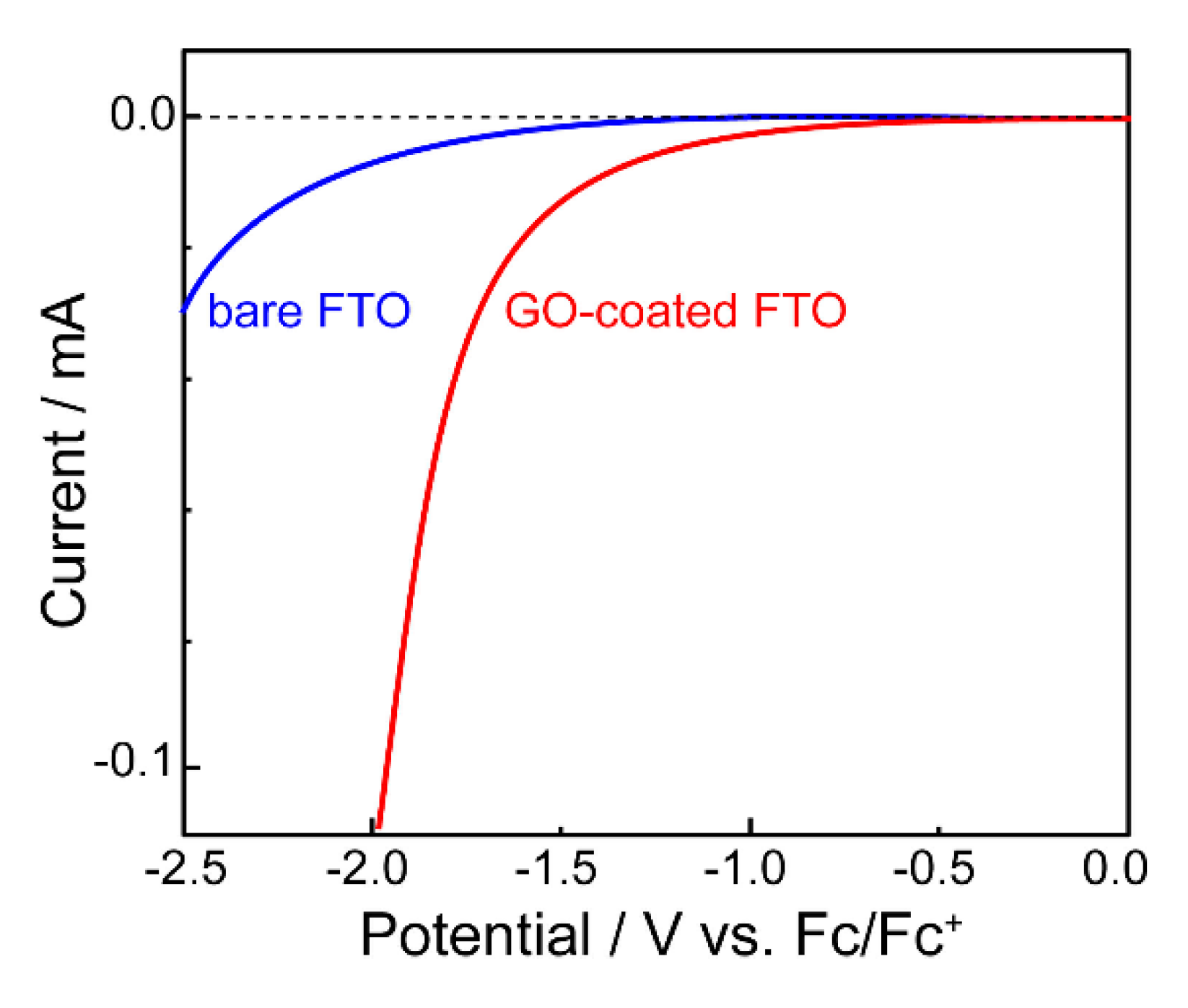
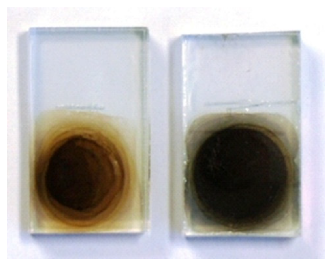
The electrochemical reduction of GO is generally carried out in aqueous electrolyte solutions, but since GO is water dispersible, it is necessary to immobilize GO on the electrode by prior chemical treatment [14]. We carried out the electrochemical reduction of GO in organic solvents, taking advantage of the fact that GO does not detach from the electrode in organic solvents as compared to aqueous systems [15]. For the electrochemical reduction of GO, platinum and indium–tin oxide (ITO) could be used as working electrodes, but the reduction reaction proceeded more effectively when fluorine-doped tin oxide (FTO), which can be applied in a wide potential window, was used. Figure 2 shows the linear sweep voltammetry (LSV) of the system using propylene carbonate (PC) as the organic solvent, tetraethylammonium tetrafluoroborate (Et4NBF4) as the supporting electrolyte, and FTO coated with a drop-cast film of GO as the working electrode. For comparison, the LSV data using only FTO without GO coating (bare FTO) as the working electrode are also shown. The reduction current flowed from around −0.5 V vs. Fc/Fc+, indicating that electrochemical reduction of GO is possible. When the applied potential became more negative than −1.0 V at LSV, the color of the film changed from brown to black, suggesting that GO was changing to rGO (Figure 3). Electrochemically reduced GO is henceforth referred to as “erGO”.
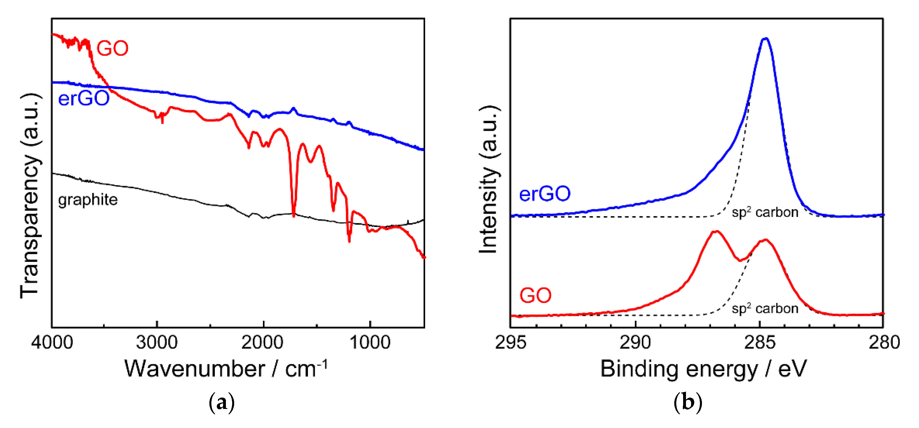
Fourier Transform Infrared (FT-IR) and X-ray photoelectron spectroscopy (XPS) were measured to identify the chemical structure of erGO (Figure 4). Although no significant absorption bands were observed in the raw graphite, absorption bands originating from C=O stretching vibration of the carbonyl group, angular vibration of the carboxyl group, and C–OH stretching vibration of the hydroxyl group were observed in GO powder at 1740, 1370, and 1220 cm−1, respectively. However, after the electrochemical reduction of GO, the characteristic absorption bands were no longer observed in the spectrum of the films as in graphite, suggesting that most of the oxygen-containing groups were removed by the electrochemical reduction. In addition, the C1s spectra in XPS showed that the signal derived from oxidized species in GO almost completely disappeared by electrochemical reduction. In order to investigate the electrical properties of erGO, the electrical conductivity of erGO films was measured by the four-probe method and found to be about 3 S cm−1, which is comparable to that of rGO obtained by chemical reduction with hydrazine.
In addition to its high electrical conductivity, graphene has a large specific surface area of 2600 m2 g−1, which makes it promising as an electrode material for electric double-layer capacitors (EDLCs). EDLC is one of the electronic components used in a wide range of industries as a backup power source for integrated circuit (IC) and large-scale integration (LSI) memories and actuators. The sweep rate dependence of the specific capacity of EDLC prepared using erGO obtained by electrochemical reduction in propylene carbonate (PC) is shown in Figure 5. Although the rate of decrease in specific capacitance was about 20% compared to that at 10 mV s−1, it was found that the specific capacitance was maintained to some extent.
3.2. Preparation of Alternating Layer Films with Conducting Polymers
In erGO, many oxygen groups are removed after reduction, and the graphene-like π-conjugated structure is reconstructed, resulting in stronger π-plane interactions. Therefore, erGO single component films do not provide as high a surface area as expected because they tend to stack similar to graphite. One of the promising methods to increase capacitance is to add pseudo-capacitance based on redox reaction, and conducting polymers are attracting attention as a material to be used for providing pseudo-capacitance [16,17]. However, because it has been difficult to find an efficient way to composite graphene with conducting polymers, the conventional method suffers from degradation due to swelling and disintegration during repeated redox reactions, resulting in a decrease in the cycle life.
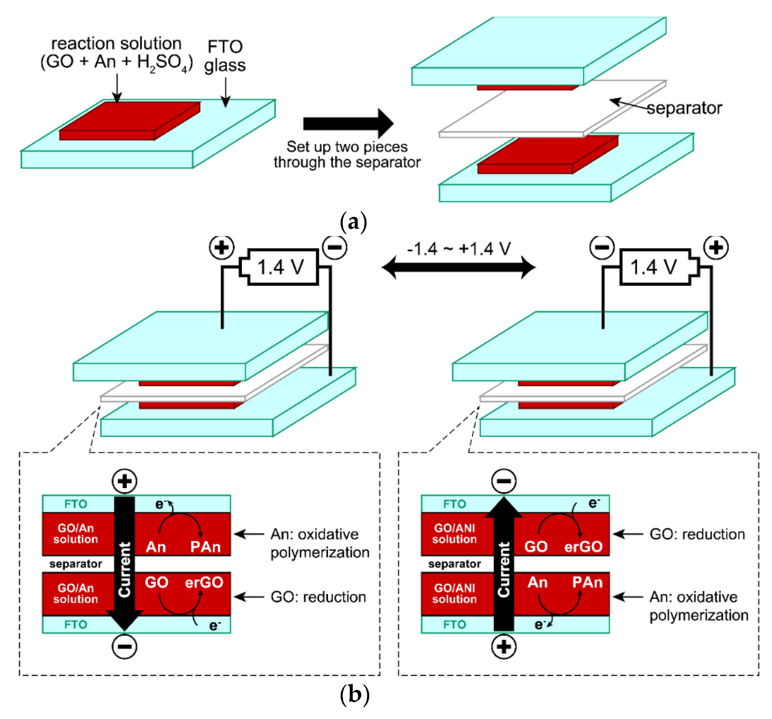
We have developed an easy method to fabricate alternating layered films of rGO and conducting polymers by taking advantage of the fact that conducting polymers can be easily synthesized by electrochemical oxidative polymerization and that the resulting polymer films are deposited on the electrode surface [18,19]. We focused on the fact that among conducting polymers, polyaniline (PAn) and polypyrrole (PPy) can be synthesized using relatively inexpensive and water-soluble aniline (An) and pyrrole (Py) as starting materials, and we developed an efficient method to fabricate alternating layered films by the following method using a two-electrode cell. GO aqueous dispersion containing sulfuric acid and An was cast on the FTO electrode and then sandwiched through the spacer (Figure 6a). In order to obtain PAn by electrochemical oxidative polymerization of An, the monomer An must be oxidized to generate cation radicals. However, if the resulting PAn is subjected to a high oxidation state (peroxidation state), it will degrade due to oxidative decay [20,21], so the applied voltage should be as low as possible. Therefore, optimization of the voltage applied to the cell was carried out. As a result, it was found that the lowest voltage at which PAn could be obtained was 1.4 V, so a voltage of −1.4 V~+1.4 V was applied between the two electrodes. On the other hand, GO is sufficiently electrolytically reduced at −1.4 V to produce erGO, but once GO is reduced to yield erGO, erGO is not re-oxidized back to GO at a voltage of about +1.4 V. Therefore, if a voltage of +1.4 V and −1.4 V is applied to both electrodes alternately, erGO and PAn are generated alternately on both electrodes, and two composite films are produced simultaneously (Figure 6b). It is also possible to fabricate composite films in which erGO and PAn are uniformly dispersed across each other by applying voltage in a scanning manner in this system. When PAn is oxidized, it incorporates the anionic moiety of the electrolyte in solution (doping), and when it is reduced, it releases the anion (de-doping). When the voltage is scanned, the doping/de-doping process smoothly takes place and the molecular chains of PAn can easily form a stable network. It can also be expected that the specific surface area of erGO will increase as PAn inserts between each layer of erGO sheets and props up each sheet.
An example of the cyclic voltammogram (CV) of the erGO/PAn composite film obtained by this method is shown in Figure 7. The current flowing from around ±1.1 V is the oxidation current of An. The peak current at around ±0.26 V seen immediately after the start of the voltage scan is thought to be due to the redox reaction of quinone/hydroquinone groups, which is also seen in other carbon materials [22,23]. This peak current disappears after 50 voltage scans, suggesting that GO has been completely reduced and converted to erGO. The large peak current at around 0 V is the redox wave of PAn that continues to be generated on the electrode. The behavior of the CV curves indicates that the electrochemical oxidation of An acts as well as the electrode reaction of the counter electrode when GO is electrochemically reduced to produce erGO. When voltage was applied to the solution containing only GO without An, almost no current was observed and the electrochemical reduction of GO did not proceed.
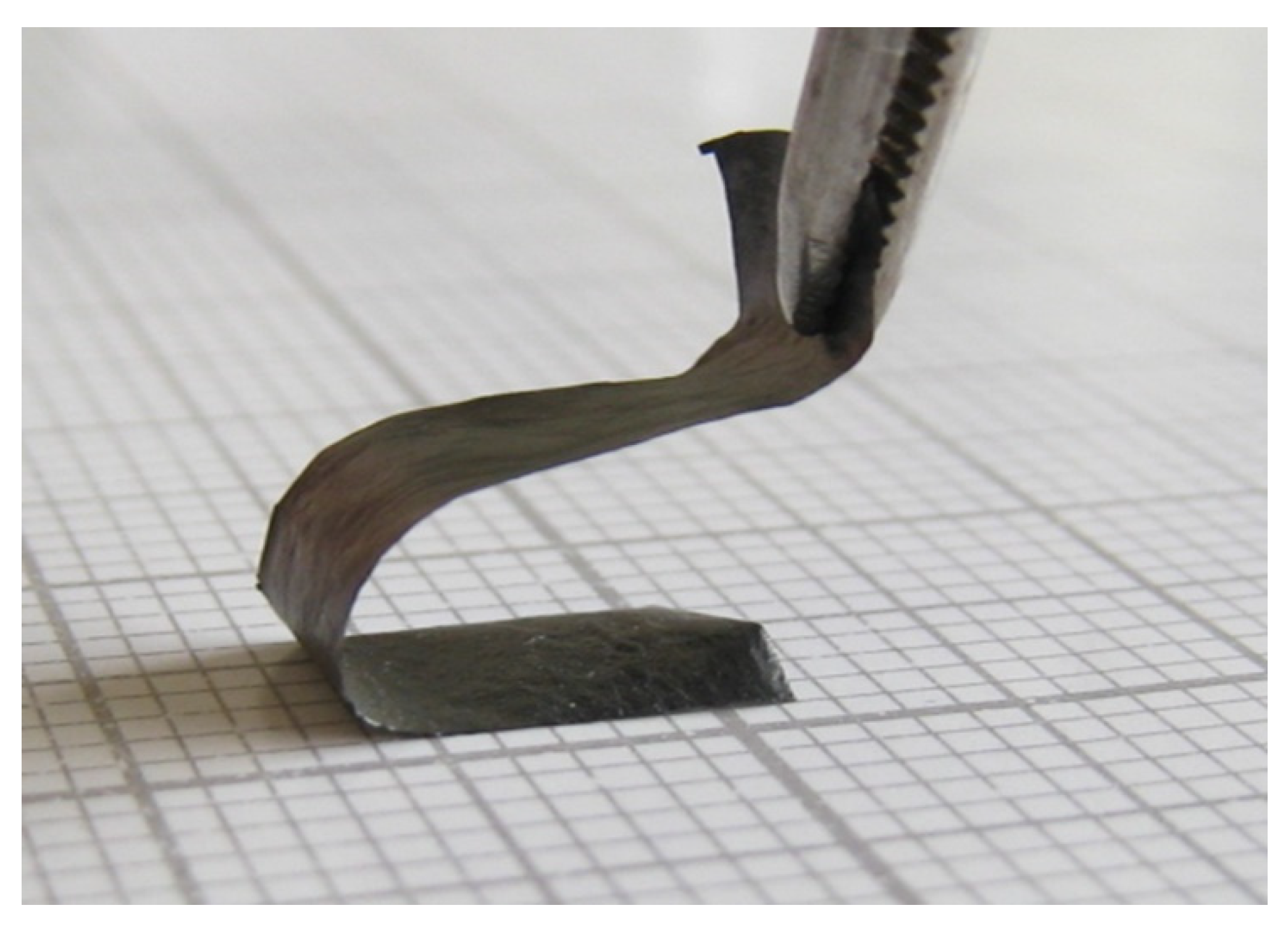
The brittleness of the resulting erGO/PAn composite film was reduced due to the uniform dispersion of PAn between the erGO sheets, and the film was easily peeled off from the FTO electrode to obtain a self-standing film. The film was flexible and could be bent or folded at sharp angles (Figure 8). It can also be cut out into any desired shape. These characteristics are beneficial properties when considering practical applications (especially wearable devices). The electrical conductivity of the composite film was 70 S cm−1, which is significantly higher than that of erGO film (3 S cm−1) and PAn nanofiber film (2 S cm−1) [24].
The capacitance of EDLC with the obtained erGO/PAn composite film was significantly affected by the mass ratio of GO and An in the reaction solution (GO:An ratio), and the highest capacitance of 205 F g−1 was obtained when the GO:An ratio was 4:1 (H2SO4 concentration: 2.0 mol dm−3). EDLCs using erGO/PAn composite films obtained from the reaction solutions with different GO:An ratios (2:1, 4:1, and 16:1), denoted as erGO/PAn-2:1, erGO/PAn-4:1, and erGO-PAn-16:1, respectively, were repeatedly charged and discharged under the same voltage scanning conditions as in Figure 7, and their cycle life was investigated (Figure 9). At the beginning of the cycle, their capacities were 159 F g−1 for erGO/PAn-2:1, 206 F g−1 for erGO/PAn-4:1, and 193 F g−1 for erGO/PAn-16:1. The capacities of all of them decreased slightly by repetition of charging and discharging. Further charge–discharge cycles were repeated, and when the number of cycles exceeded 3000, the capacity became constant regardless of the number of cycles. Even after 20000 cycles, the capacities of erGO/PAn-2:1, erGO/PAn-4:1, and erGO/PAn-16:1 remained at 95 F g−1, 141 F g−1, and 160 F g−1, respectively, all showing a good cycle life.
As a new application of the resulting rGO/conducting polymer composite films, we also investigated their thermoelectric properties. Thermoelectric devices, which can directly convert thermal energy into electrical energy, have long been used as power sources, such as space probes (such as “Voyager”) in faraway places where sunlight cannot reach, and are coming back into the limelight as a technology to recover unused heat. Organic thermoelectric materials using conducting polymers (polythiophene and polyaniline) and nanocarbon compounds (carbon nanotubes and graphene) have been attracting attention for their application to the recovery of unused heat. We have also been working on the development of thermoelectric materials based on polythiophenes with various molecular structures [25,26,27,28,29,30,31] and their composites with carbon nanotubes [32]. As part of these studies, we also investigated the thermoelectric properties of the erGO/PAn composite film prepared by the method shown above.
The performance of thermoelectric materials is evaluated to be excellent when the ZT value shown in Equation (1) is large.
where σ is the electrical conductivity, S is the Seebeck coefficient, κ is the thermal conductivity, T is the operating environment temperature, and PF is the power factor (). In this study, we investigated the effect of the fabrication conditions of the composite film on the ZT value.
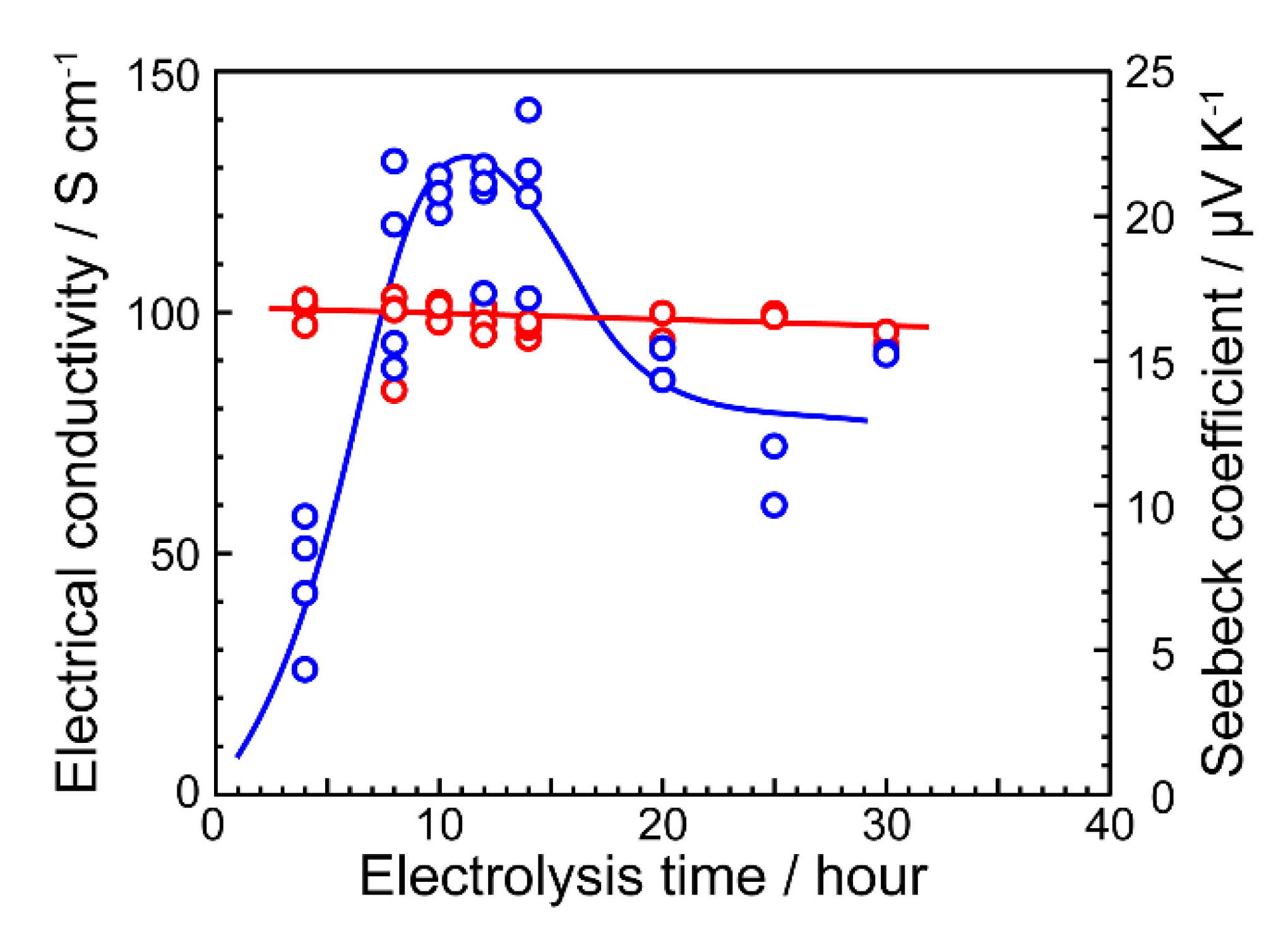
Two methods of fabricating composite films were investigated: (1) the potential scanning method, where a voltage is applied in a triangular wave in the range of ±1.4 V and (2) the potential stepping method, where two potentials of +1.4 V and −1.4 V are applied alternately. Two types of substrates, FTO and stainless steel (SUS), were investigated for the working electrode. It was found that the thermoelectric properties of the resulting composite films were significantly affected by the combination of these factors. Among them, the composite film prepared by the potential step method using an SUS plate as the working electrode showed the highest thermoelectric performance. The thermoelectric properties of the composite films were also found to be affected by the electrolysis treatment time, and the electrical conductivity started to increase rapidly after 5 h of treatment and reached its highest value after about 10 h (Figure 10). However, when the electrolytic treatment time exceeded 15 h, the electrical conductivity began to decrease. This was attributed to the peroxidation of PAn caused by the prolonged electrolytic treatment. On the other hand, the Seebeck coefficient did not change significantly with the electrolysis time. As a result, the power factor was also affected by the large change in electrical conductivity and showed the highest value around 10 h of electrolysis treatment time. In general, the thermal conductivity of graphene alone is very high, 3000 W m−1 K−1, which works as a disadvantage to reduce the ZT value. However, by compositing with PAn, which has a relatively low thermal conductivity of 0.1~0.3 W m−1 K−1, the thermal conductivity of the composite films could be reduced to 0.05~0.85 W m−1 K−1, resulting in a maximum ZT value of 0.024 for the composite films.
4. Thermal Reduction
4.1. Application to Transparent Conductive Films with High Mechanical Strength by Combination with Silica
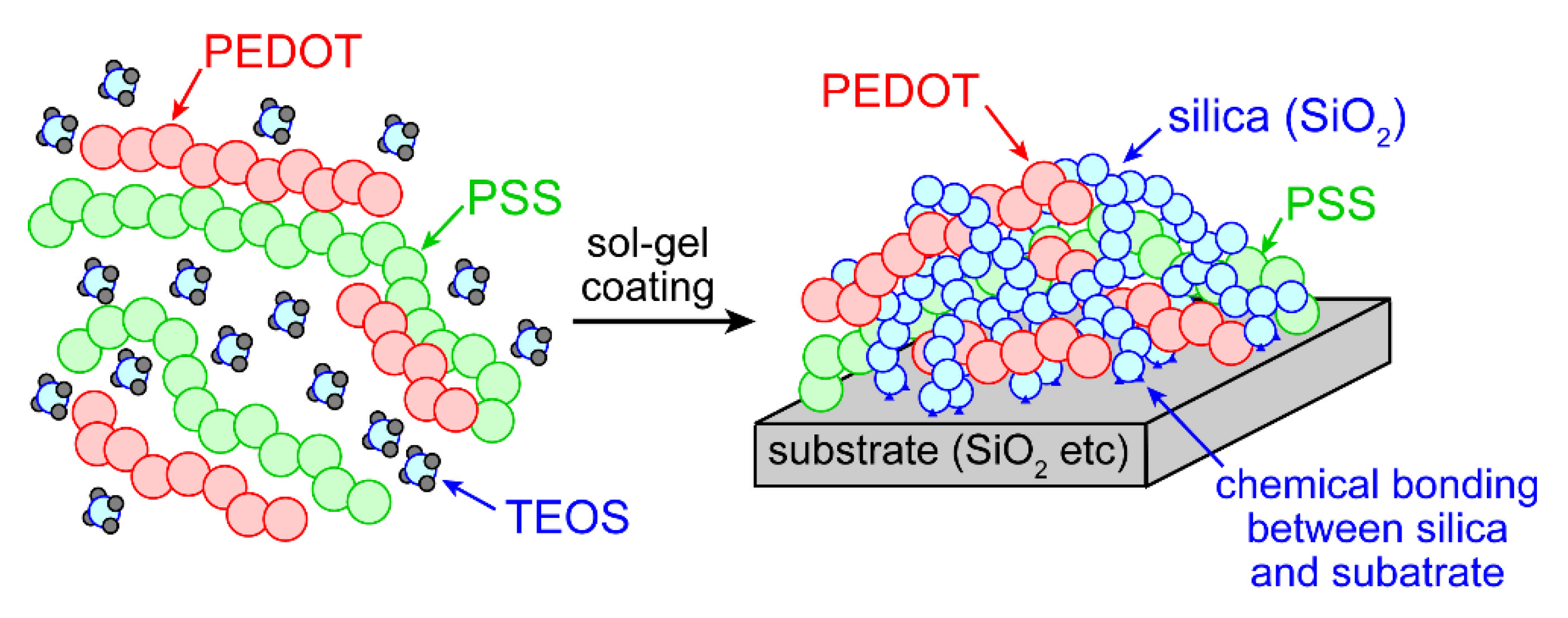
When extremely thin graphene films are applied to glass substrates, transparent conductive films can be produced due to the excellent electrical conductivity and transparency of graphene. However, graphene is brittle and does not adhere well to the glass substrate, which causes the problem of graphene detaching from the glass substrate after long-term use. We have previously reported that when tetraethyl orthosilicate (TEOS) is added to an aqueous dispersion of a commercially available conducting polymer, a composite of poly(3,4-ethylenedioxythiophene) and poly(4-styrenesulfonic acid) (PEDOT:PSS, Figure 11), the water and acid (sulfonic acid in PSS) cause a sol–gel reaction of TEOS to form a composite of PEDOT:PSS and silica. The resulting silica can adhere to the surface of the glass substrate through chemical bonds (Figure 12), and we have succeeded in developing transparent conductive films with excellent mechanical properties such as scratch hardness and adhesion strength [36]. In addition, while this film has excellent transparency in the visible light range, it has high absorption of near-infrared light. Therefore, it is highly expected that this feature can be used to make this film applicable to heat-shielding materials [37].
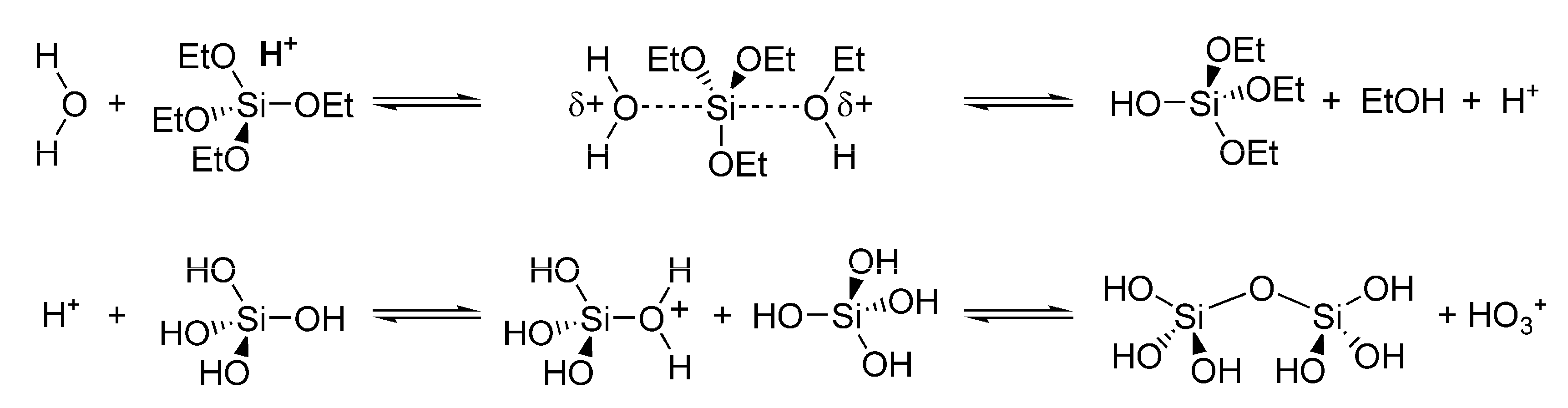
The sol–gel reaction used here is a reaction in which organometallic and inorganic compounds (such as TEOS and tetrachlorosilane) containing the target metal are hydrolyzed and polycondensed in the presence of an acid or basic catalyst and water to produce metal oxides [38,39]. For example, multifunctional alkoxysilanes and halosilanes can easily yield silicon dioxide (silica, SiO2) by sol–gel reaction (Figure 13). This technique has been applied in various fields as a simple method to fabricate metal oxide thin films. Silica-like polymers (polysilsesquioxane), in which one of the substituents on the silicon atom is replaced by an organic group, can also be synthesized by the same method, and various functions can be introduced by the organic substituents [40,41,42,43,44,45,46,47].
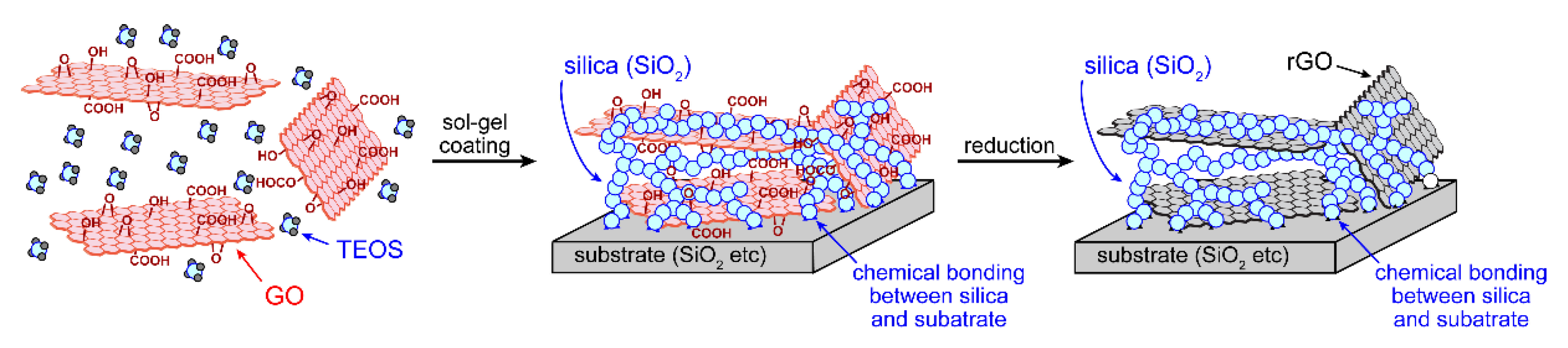
Since GO is obtained by oxidizing graphite under acidic conditions and exfoliating it in water and the product contains many acidic functional groups such as hydroxyl and carboxyl groups, the aqueous dispersion of GO can be obtained in an acidic state. Hence, it is expected that the GO acidic aqueous dispersion with these characteristics can be used to achieve the following: when TEOS is added to the GO acidic aqueous dispersion, the sol–gel reaction proceeds simply by mixing, and the GO/silica composite film can be obtained by coating the resulting solution on a substrate. Finally, the GO/silica film is annealed in air or a vacuum to produce the graphene/silica composite film (Figure 14). If the substrate is a metal oxide such as silica glass or ITO, the graphene/silica composite film can be strongly fixed to the substrate via chemical bonding due to the dehydration condensation between the hydroxyl groups on the substrate surface and the silanol at the end of the molecular chain of silica in the film. Based on this idea, graphene/silica composite films were synthesized by the following method [48,49]: TEOS was added to the GO acidic aqueous dispersion in the proportions shown in Table 1 and stirred for 12 h at room temperature. A phase separation between TEOS and GO aqueous dispersion was observed immediately after TEOS was added to the GO acidic aqueous dispersion. However, the solution became homogeneous (sol state) as the reaction progressed and hydrophilic silanols were formed. The resulting mixed solution was spin-coated onto a glass or quartz substrate and subjected to thermal reduction (reduction conditions: 300 °C in air, 300 °C in a vacuum, 500 °C in a vacuum, and 800 °C in a vacuum) to produce a composite film of thermally reduced GO (“trGO”) and silica. Among the films prepared by the feed ratios shown in Table 1, GS27 with the highest silica content was visually confirmed to be inhomogeneous, probably due to phase separation between trGO and silica. Therefore, further investigations were performed only for the composite films with a silica content less than 23 mol % (trGO~GS23).
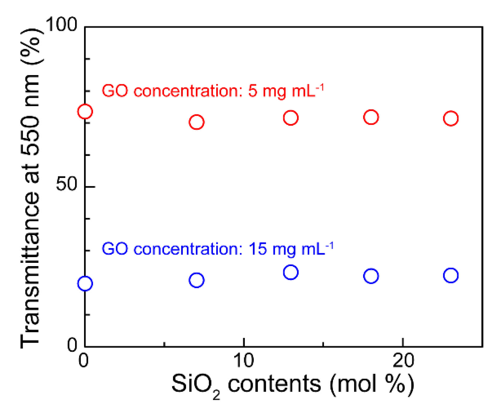
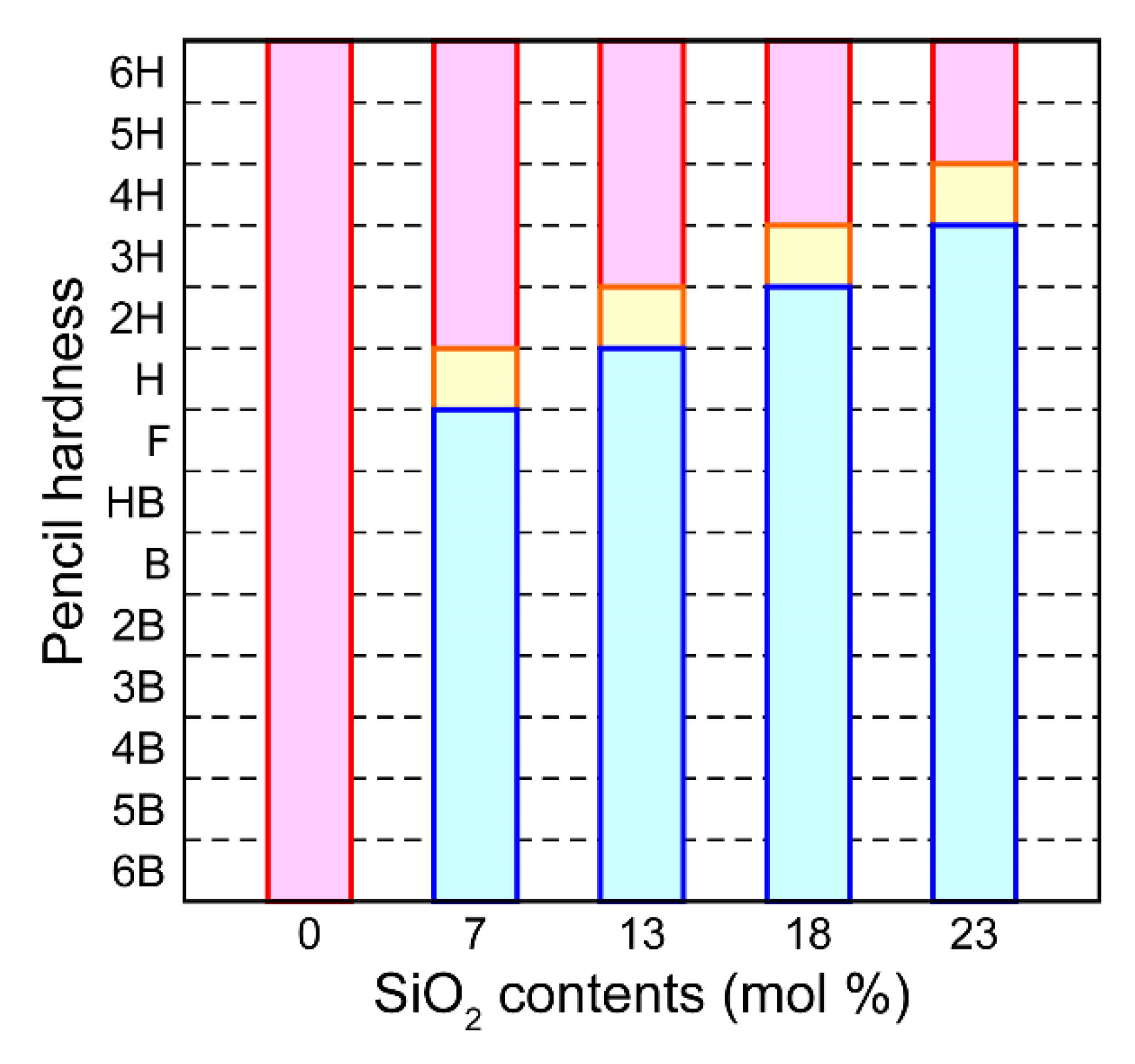
First, we investigated the effect of the concentration of GO water dispersion on the transparency of the films (Figure 15). As a result, the transmittance of the film prepared using the solution with a GO concentration of 5 mg mL−1 was maintained at about 80% of that of the glass substrate alone, indicating that the film had relatively high transparency. Next, the effect of the silica concentration in the films was investigated, and it was found that the transmittance of the films was not significantly affected by changes in the composite ratio of trGO to silica (Figure 16). The mechanical strength of the films was evaluated using a pencil scratch hardness tester [50], and it was confirmed that the films of trGO alone peeled off when scratched with pencils of all harnesses in the range of 6B~6H. On the other hand, the strength of the trGO/silica composite film increased as the silica content and the annealing temperature of the film increased, and GS23 fabricated at 800 °C in a vacuum showed no damage to the film even when scratched with a 3H hardness pencil (Figure 17). The electrical conductivity of the films was evaluated, and it was found that the electrical conductivity tended to decrease as the silica content in the film increased, while it tended to increase as the heat treatment temperature of the film increased (Figure 18). The correlation between the strength of the films and the electrical conductivities was investigated and it was found that the optimum relationship between the strength and the electrical conductivity was established in the case where the scratching strength of the film was F and the electrical conductivity was 32 S cm−1 (Figure 19).
4.2. Application to Anode Materials for Lithium-Ion Secondary Batteries with High Capacity and High Durability
In 2019, Goodenough, Whittingham, and Yoshino were awarded the Nobel Prize in Chemistry for their achievements in research and development on lithium-ion batteries (LIBs). Rechargeable batteries, which can be used repeatedly by recharging, have already been put to practical use as a power source for mobile phones and laptop computers and are also expected to be further developed as a power source for electric vehicles in the future [51,52,53,54]. Among rechargeable batteries, LIBs have attracted the most interest because of their high energy density, light weight, and high output voltage. Yoshino is the first person in the world to devise and manufacture a prototype rechargeable battery of today’s LIBs, using graphite as the anode and lithium cobalt oxide (LiCoO2) as the cathode. He also developed the basic LIB technology of using aluminum (Al) as the positive electrode current collector, as well as the electrode, battery, and peripheral technologies necessary for practical use, resulting in the commercialization of the LIB, a new type of compact and lightweight rechargeable battery.
In LIBs using graphite as anode materials, lithium ions are intercalated and deintercalated between the layers of graphite during charging and discharging (Equation (2)).
6 C + Li+ + e− ⇄ C6Li
From this equation, the theoretical capacity of carbon materials such as graphite as the anode material is 372 mAh g−1. Currently developed LIBs have already achieved values close to this theoretical capacity, and the development of new materials with higher capacity is eagerly awaited in order to expand their applications to large devices such as electric vehicles and energy storage systems. Silicon (Si) is an anode material that is currently attracting attention from this viewpoint [55,56,57,58]. The use of Si can be expected to provide a high theoretical capacity (4198 mAh g−1) based on Equation (3).
Si + 4.4 Li+ + 4.4e− ⇄ Li4.4Si
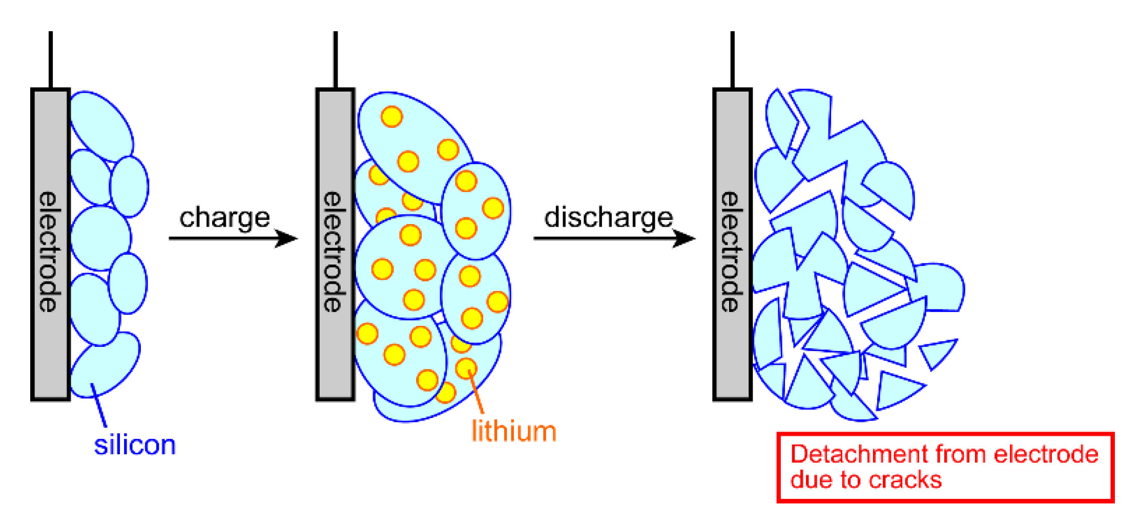
However, when Si is changed to Li4.4Si, the volume expands 3.8 times, and the stress of expansion and shrinkage of the material due to charging and discharging causes the Si to collapse and pulverize and to detach from the electrode (Figure 20). With the aim of overcoming this problem, we applied our previously developed technology for the synthesis of graphene/silica composites to synthesize graphene/Si composites [59].
While GO can be reduced to graphene (trGO) only by heat treatment at about 1000 °C, silica cannot be reduced only by heat treatment at this temperature because of its high thermal stability. Commercially, silicon has been produced in the order of hundreds of thousands of tons by reacting silica with carbon at 3000 °C in an electric furnace (Equation (4)) [60].
SiO2 + 2 C → Si + 2 CO
However, since the graphene/silica composite is used as the starting material in this study, if this composite is heated as is, the carbon component in the composite will be used to reduce the silica, as shown in Equation (4). Heat treatment at temperatures as high as 3000 °C is also industrially costly. In order to proceed the reduction of silica under mild heating conditions without consuming the graphene in the composite, we applied a reduction method using magnesium metal (Mg) (magnesiothermic reduction) [61].
The synthesis method is as follows; TEOS was added to the GO aqueous dispersion (5 mg mL−1) and stirred for 24 h. Mg powder was added to the obtained GO/silica composite, dispersed by sonication, and dried at 80 °C. After the dried samples were heat-treated (800 °C, vacuum), the graphene/Si composites were prepared by removing the byproducts of Mg-based compounds (MgO, Mg2Si, etc.) with hydrochloric acid and the remaining silica with hydrofluoric acid.
In order to evaluate the structure of the obtained product, Raman spectroscopy was performed (Figure 21). In the spectrum of the sample before heat treatment, the D band derived from structural defects around 1350 cm−1 and the G band derived from the six-membered ring structure around 1600 cm−1, which are observed in graphite and graphene, were observed. On the other hand, in the spectrum of the product annealed in the presence of Mg, a sharp peak derived from Si was newly observed at around 520 cm−1. These results suggest that silica in the GO/silica composite can be reduced to Si by heat treatment in the presence of Mg.
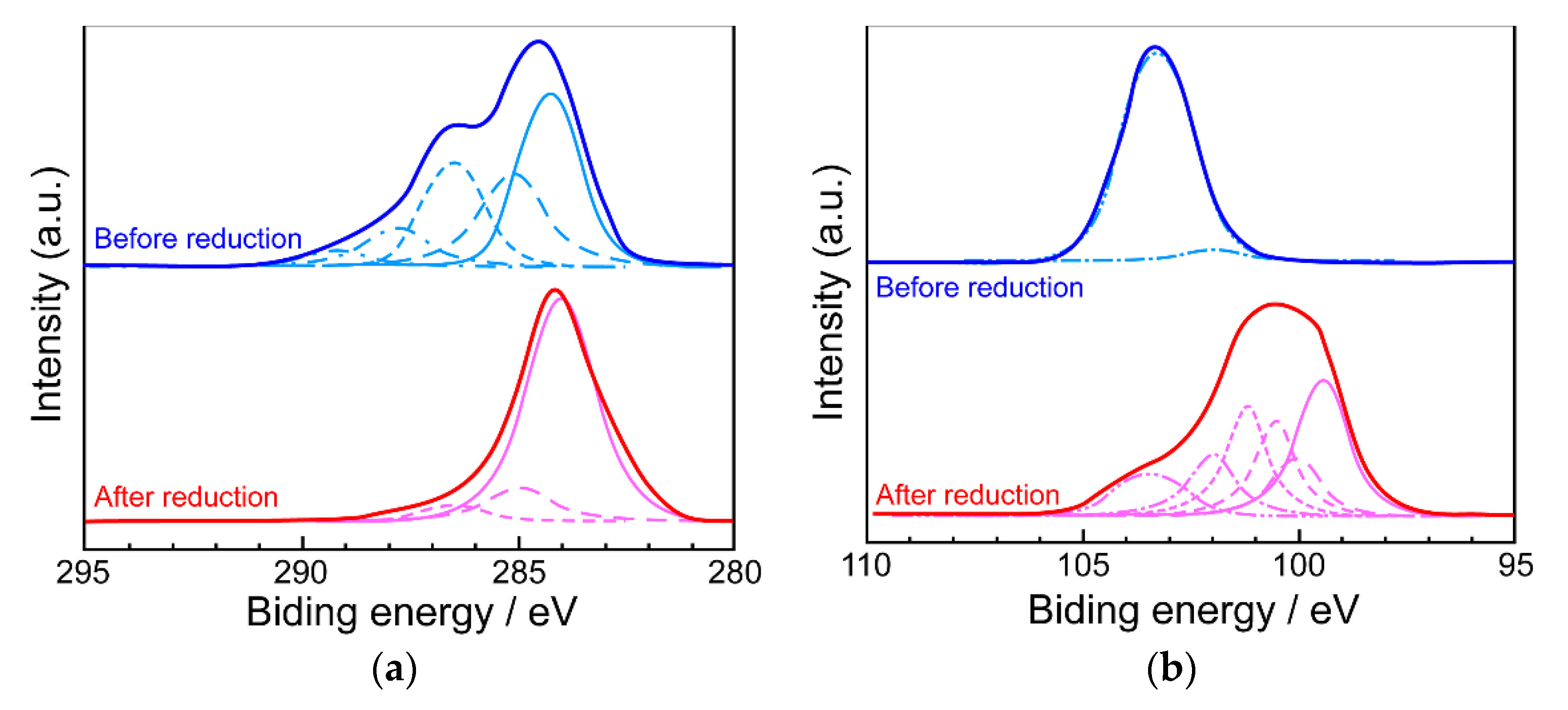
XPS measurements were also performed to analyze the composition of the composite (Figure 22). The C1s spectra showed that the signals derived from sp3 carbon (285 eV) and the oxygen group (286~288 eV) in GO almost disappeared, and the signal intensity derived from sp2 carbon (284.3 eV) increased in the composite obtained by annealing in the presence of Mg. The Si2p spectrum showed that only one signal derived from silica was observed around 103.5 eV in the GO/silica spectrum, but when the composite was heated in the presence of Mg, the intensity of this signal was greatly reduced and new signals derived from Si (99.5~99.8 eV) and partially oxidized silicon (SiOx, 0 < x < 2, 100.1~102.0 eV) were observed. These results indicate that both GO and silica could be reduced by heat treatment in the presence of magnesium, although not completely. The composite obtained by the magnesiothermic reduction is hereafter referred to as “mrGO/Si”.
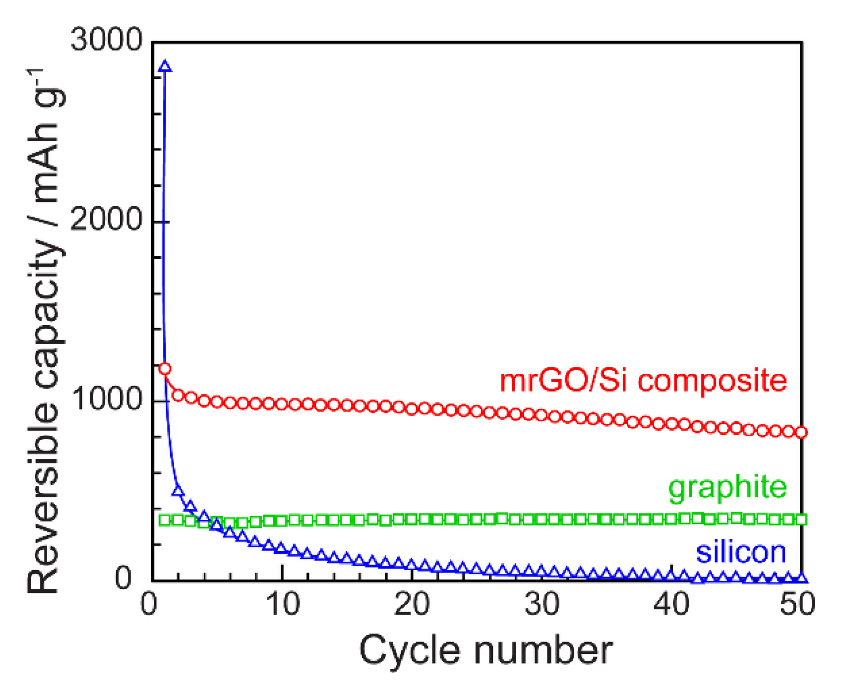
A battery using the obtained mrGO/Si composite as the anode material was fabricated and its charge–discharge characteristics were investigated. The initial capacity of the LIB fabricated with the mrGO/Si composite film was lower than that of the battery fabricated with silicon alone, but about four times higher than that of the battery fabricated with graphite. We also found that the cycle stability of LIB with mrGO/Si composite was superior to that of LIB with silicon (Figure 23).
5. Summary and Perspectives
In this review, our recent topics on the synthetic method of reduced graphene oxide (rGO) using graphene oxide by electrochemical or thermal reduction were presented. It was found that the rGO synthesized in this way can be used as important electrode materials in energy storage devices such as electric double-layer capacitors and lithium-ion batteries, transparent conductive films that allow electricity to flow while being transparent, and thermoelectric conversion devices that can recover electric energy from unused and discarded thermal energy. Since there is no need to use highly toxic reagents and the reaction is clean in that it uses water as the solvent, this method has a low environmental impact from the perspective of industrialization, which is in line with the “Sustainable Development Goals (SDGs)”.
As mentioned earlier, graphene oxide can also be chemically reduced by food-related materials such as vitamin C. The disadvantage of this method is its low reaction efficiency, but it is very attractive from the perspective of environmental friendliness. This method, in combination with electrochemical or thermal reduction techniques, may lead to the synthesis of graphene-like compounds with even higher efficiency and environmental friendliness. It is also very interesting to introduce microwaves. A novel GO reduction method combining these two methods is currently under investigation.
Funding
This research received no external funding.
Institutional Review Board Statement
Not applicable.
Informed Consent Statement
Not applicable.
Conflicts of Interest
The author declares no conflict of interest.
References
- Rashid bin Mohd Yusoff, A. Graphene-Based Energy Devices; Wiley-VCH: Weinheim, Germany, 2015. [Google Scholar]
- Stankovich, S.; Dikin, D.A.; Piner, R.D.; Kohlhaas, K.A.; Kleinhammes, A.; Jia, Y.; Wu, Y.; Nguyen, S.B.T.; Ruoff, R.S. Synthesis of graphene-based nanosheets via chemical reduction of exfoliated graphite oxide. Carbon 2007, 45, 1558–1565. [Google Scholar] [CrossRef]
- Pei, S.; Zhao, J.; Du, Z.; Ren, W.; Cheng, H.-N. Direct reduction of graphene oxide films into highlyconductive and flexible graphene films by hydrohalic acids. Carbon 2010, 48, 4466–4474. [Google Scholar] [CrossRef]
- Chen, W.; Yan, L. In situ self-assembly of mild chemical reduction graphene for three-dimensional architectures. Nanoscale 2011, 3, 3132–3137. [Google Scholar] [CrossRef] [PubMed]
- Xu, Y.-L.; Qi, J.-M.; Sun, F.-F.; Ma, N. Carbocatalysis: Reduced graphene oxide-catalyzed Boc protection of hydroxyls and graphite oxide-catalyzed deprotection. Tetrahedron Lett. 2015, 56, 2744–2748. [Google Scholar] [CrossRef]
- Liu, Y.; Feng, J. An attempt towards fabricating reduced graphene oxide composites with traditional polymer processing techniques by adding chemical reduction agents. Comp. Sci. Technol. 2017, 140, 16–22. [Google Scholar] [CrossRef]
- Dong, L.; Yang, J.; Chhowalla, M.; Loh, K.P. Synthesis and reduction of large sized graphene oxide sheets. Chem. Soc. Rev. 2017, 46, 7306–7316. [Google Scholar] [CrossRef] [PubMed]
- López-Diaz, D.; Merchán, M.D.; Velázquez, M.M. The behavior of graphene oxide trapped at the air water interface. Adv. Colloid Int. Surf. 2020, 286, 102312. [Google Scholar] [CrossRef]
- Brodie, B.C. Researches on the atomic weight of graphite. Quart. J. Chem. Soc. Lond. 1860, 12, 261–268. [Google Scholar] [CrossRef] [Green Version]
- Staudenmaier, L. Verfahren zur Darstellung der Graphitsäure (Method for the preparation of graphitic acid). Ber. Dtsch. Chem. Ges. 1898, 31, 1481–1487. [Google Scholar] [CrossRef] [Green Version]
- Hummers, W.S., Jr.; Offeman, R.E. Preparation of graphitic oxide. J. Am. Chem. Soc. 1958, 80, 1339. [Google Scholar] [CrossRef]
- Kovtyukhova, N.I.; Ollivier, P.J.; Martin, B.R.; Mallouk, T.E.; Chizhik, S.A.; Buzaneva, E.V.; Gorchinskiy, A.D. Layer-by-layer assembly of ultrathin composite films from micron-sized graphite oxide sheets and polycations. Chem. Mater. 1999, 11, 771–778. [Google Scholar] [CrossRef]
- Marcano, D.C.; Kosynkin, D.V.; Berlin, J.M.; Sinitskii, A.; Sun, Z.; Slesarev, A.; Alemany, L.B.; Lu, W.; Tour, J.M. Improved synthesis of graphene oxide. ACS Nano 2010, 4, 4806–4814. [Google Scholar] [CrossRef]
- Shao, Y.; Wang, J.; Engelhard, M.; Wang, C.; Lin, Y. Facile and controllable electrochemical reduction of graphene oxide and its applications. J. Mater. Chem. 2010, 20, 743–748. [Google Scholar] [CrossRef]
- Harima, Y.; Setodoi, S.; Imae, I.; Komaguchi, K.; Ooyama, Y.; Ohshita, J.; Mizota, H.; Yano, J. Electrochemical reduction of graphene oxide in organic solvents. Electrochim. Acta 2011, 56, 5363–5368. [Google Scholar] [CrossRef]
- Kötz, R.; Carlen, M. Principles and applications of electrochemical capacitors. Electrochim. Acta 2000, 45, 2483–2498. [Google Scholar] [CrossRef]
- Snook, G.A.; Kao, P.; Best, A.S. Conducting-polymer-based supercapacitor devices and electrodes. J. Power Sources 2011, 196, 1–12. [Google Scholar] [CrossRef]
- Jiang, X.; Setodoi, S.; Fukumoto, S.; Imae, I.; Komaguchi, K.; Yano, J.; Mizota, H.; Harima, Y. An easy one-step electrosynthesis of graphene/polyaniline composites and electrochemical capacitor. Carbon 2014, 67, 662–672. [Google Scholar] [CrossRef]
- Imae, I.; Fujimoto, D.; Zhang, L.; Harima, Y. Electrosynthesis of a multilayer film stacked alternately by poly (3,4-ethylenedioxythiophene) and reduced graphene oxide from aqueous solution. Electrochem. Commun. 2017, 81, 65–69. [Google Scholar] [CrossRef]
- Kobayashi, T.; Yoneyama, H.; Tamura, H. Oxidative degradation pathway of polyaniline film electrodes. J. Electroanal. Chem. Int. Electrochem. 1984, 177, 293–297. [Google Scholar] [CrossRef]
- Kabumoto, A.; Shinozaki, K.; Watanabe, K.; Nishikawa, N. Electrochemical degradation of polyaniline. Synth. Metals 1988, 26, 349–355. [Google Scholar] [CrossRef]
- Shao, Y.; Yin, G.; Zhang, J.; Gao, Y. Comparative investigation of the resistance to electrochemical oxidation ofcarbon black and carbon nanotubes in aqueous sulfuric acid solution. Electrochim. Acta 2006, 51, 5853–5857. [Google Scholar] [CrossRef]
- Wang, G.; Yang, J.; Park, J.; Gou, X.; Wang, B.; Liu, H.; Yao, J. Facile synthesis and characterization of graphene nanosheets. J. Phys. Chem. C 2008, 112, 8192–8195. [Google Scholar] [CrossRef]
- Zhang, Y.; Jiang, X.; Zhang, R.; Sun, P.; Zhou, Y. Influence of the nanostructure on charge transport in polyaniline films. Electrochim. Acta 2011, 56, 3264–3269. [Google Scholar] [CrossRef]
- Zhang, L.; Goto, T.; Imae, I.; Sakurai, Y.; Harima, Y. Thermoelectric properties of PEDOT films prepared by electrochemical polymerization. J. Polym. Sci. Part B Polym. Phys. 2017, 55, 524–531. [Google Scholar] [CrossRef]
- Imae, I.; Akazawa, R.; Harima, Y. Seebeck coefficients of regioregular poly(3-hexylthiophene) correlated with doping levels. Phys. Chem. Chem. Phys. 2018, 20, 738–741. [Google Scholar] [CrossRef] [PubMed]
- Imae, I.; Koumoto, T.; Harima, Y. Thermoelectric properties of polythiophenes partially substituted by ethylenedioxy groups. Polymer 2018, 144, 43–50. [Google Scholar] [CrossRef]
- Imae, I.; Shi, M.; Ooyama, Y.; Harima, Y. Seebeck coefficients of poly(3,4-ethylenedioxythiophene):poly(styrene sulfonate) correlated with oxidation levels. J. Phys. Chem. C 2019, 123, 4002–4006. [Google Scholar] [CrossRef]
- Imae, I.; Kataoka, H.; Harima, Y. Flexible thermoelectric materials based on conducting polymers doped with silicone polymer electrolyte. Mol. Cryst. Liquid Cryst. 2019, 685, 100–106. [Google Scholar] [CrossRef]
- Imae, I.; Goto, T.; Ooyama, Y.; Harima, Y. Thermoelectric properties of poly(3,4-thylenedioxythiophene) with fluorine-containing polyanion as dopant. Polymer 2020, 199, 122538. [Google Scholar] [CrossRef]
- Imae, I.; Akazawa, R.; Ooyama, Y.; Harima, Y. Investigation of organic thermoelectric materials using potential-step chronocoulometry: Effect of polymerization methods on thermoelectric properties of poly(3-hexylthiophene. J. Polym. Sci. 2020, 58, 3004–3008. [Google Scholar] [CrossRef]
- Zhang, L.; Harima, Y.; Imae, I. Highly improved thermoelectric performances of PEDOT:PSS/SWCNT composites by solvent treatment. Org. Electron. 2017, 51, 304–307. [Google Scholar] [CrossRef]
- Tseluikin, V.N.; Vasilenko, E.A. Electrodeposition and properties of composite coating based on nickel. Russ. J. Appl. Chem. 2011, 84, 1920–1922. [Google Scholar] [CrossRef]
- Jabbar, A.; Yasin, G.; Khan, W.Q.; Anwar, M.Y.; Korai, R.M.; Nizam, M.N.; Muhyodin, G. Electrochemical deposition of nickel graphene composite coatings: Effect of deposition temperature on its surface morphology and corrosion resistance. RSC Adv. 2017, 7, 31100–31109. [Google Scholar] [CrossRef] [Green Version]
- Gajewska-Midziałek, A. Composite coatings with nickel matrix and graphene as dispersed phase. Pol. J. Chem. Technol. 2018, 20, 54–59. [Google Scholar] [CrossRef] [Green Version]
- Imae, I.; Nakamura, Y.; Komaguchi, K.; Ooyama, Y.; Ohshita, J.; Harima, Y. Development of a simple method for fabrication of transparent conductive films with high mechanical strength. Sci. Technol. Adv. Mater. 2012, 13, 045005. [Google Scholar] [CrossRef] [PubMed] [Green Version]
- Tsukada, S.; Nakanishi, Y.; Kai, H.; Ishimoto, T.; Okada, K.; Adachi, Y.; Imae, I.; Ohshita, J. NIR-shielding films based on PEDOT-PSS/polysiloxane and polysilsesquioxane hybrid. J. Appl. Polym. Sci. 2020, 137, 48367. [Google Scholar] [CrossRef]
- Wright, J.D.; Sommerdijk, N.A.J.M. Sol-Gel Materials: Chemistry and Applications; Gordon and Breach Science Publishers: Singapore, 2000. [Google Scholar]
- Schubert, U. Chemistry and fundamentals of the sol–gel process. In The Sol-Gel Handbook; Levy, D., Zayat, M., Eds.; Wiley-VCH: Weinheim, Germany, 2015; Chapter 1; pp. 3–27. [Google Scholar]
- Imae, I.; Kawakami, Y. Unique photoluminescence property of a novel perfectly carbazole-substituted POSS. J. Mater. Chem. 2005, 15, 4581–4583. [Google Scholar] [CrossRef]
- Imae, I.; Kawakami, Y.; Ooyama, Y.; Harima, Y. Solid state photoluminescence property of a novel POSS-based material having carbazole. Macromol. Symp. 2007, 249–250, 50–55. [Google Scholar] [CrossRef]
- Kawakami, Y.; Lee, D.W.; Pakjamsai, C.; Seino, M.; Takano, A.; Miyasato, A.; Imae, I. Formation and functionalization of aryl-substituted silsesquioxanes. ACS Symp. Ser. 2007, 954, 301–312. [Google Scholar]
- Imae, I.; Takenaka, Y.; Tokita, D.; Ooyama, Y.; Komaguchi, K.; Harima, Y. Drastic enhancement of cycle lifetime of electrochromic devices using polysilsesquioxane as an anchoring agent. Chem. Lett. 2008, 37, 964–965. [Google Scholar] [CrossRef]
- Imae, I.; Takayama, S.; Tokita, D.; Ooyama, Y.; Komaguchi, K.; Ohshita, J.; Sugioka, T.; Kanehira, K.; Harima, Y. Development of anchored oligothiophenes on substrates for the application to the tunable transparent conductive films. Polymer 2009, 50, 6198–6201. [Google Scholar] [CrossRef]
- Imae, I.; Tokita, D.; Ooyama, Y.; Komaguchi, K.; Ohshita, J.; Harima, Y. Charge transport properties of polymer films comprising oligothiophene in silsesquioxane network. Polym. Chem. 2011, 2, 868–872. [Google Scholar] [CrossRef]
- Imae, I.; Tokita, D.; Ooyama, Y.; Komaguchi, K.; Ohshita, J.; Harima, Y. Oligothiophenes incorporated in a polysilsesquioxane network: Application to tunable transparent conductive films. J. Mater. Chem. 2012, 22, 16407–16415. [Google Scholar] [CrossRef]
- Imae, I.; Takayama, S.; Tokita, D.; Ooyama, Y.; Komaguchi, K.; Ohshita, J.; Harima, Y. Synthesis of a novel family of polysilsesquioxanes having oligothiophenes with well-defined structures. Int. J. Polym. Sci. 2012, 2012, 484523. [Google Scholar] [CrossRef]
- Imae, I.; Oonishi, T.; Isaak, I.S.; Yamamoto, S.; Harima, Y. Facile fabrication of transparent conductive graphene/silica composite films with high mechanical strength. Synth. Met. 2017, 224, 33–35. [Google Scholar] [CrossRef]
- Imae, I.; Harima, Y. Method for Producing Graphene/Silica Composite. Japanese Patent No. 6437825, 22 November 2018. [Google Scholar]
- ASTM D3363-92 Test Method for Film Hardness by Pencil Test; ASTM: West Conshohocken, PA, USA, 1992.
- Ozawa, K. Lithium Ion Rechargeable Batteries; Wiley-VCH: Weinheim, Germany, 2009. [Google Scholar]
- Scrosati, B.; Abraham, K.M.; Schalkwijk, W.V.; Hassoun, J. Lithium Batteries: Advanced Technologies and Applications; John Wiley & Sons: Hoboken, NJ, USA, 2013. [Google Scholar]
- Glaize, C.; Geniès, S.J. Lithium Batteries and Other Electrochemical Storage Systems; John Wiley & Sons: Surrey, UK, 2013. [Google Scholar]
- Aifantis, K.E.; Hackney, S.A.; Kumar, R.V. High Energy Density Lithium Batteries: Materials, Engineering, Applications; Wiley-VCH: Weinheim, Germany, 2013. [Google Scholar]
- Casimir, A.; Zhang, H.; Ogoke, O.; Amine, J.C.; Lu, J.; Wu, G. Silicon-based anodes for lithium-ion batteries: Effectiveness of materials synthesis and electrode preparation. Nano Energy 2016, 27, 359–376. [Google Scholar] [CrossRef] [Green Version]
- Zuo, X.; Zhu, J.; Müller-Buschbaum, P.; Cheng, Y.-J. Silicon based lithium-ion battery anodes: A chronicle perspective review. Nano Energy 2017, 31, 113–143. [Google Scholar] [CrossRef]
- Zhu, B.; Wang, X.; Yao, P.; Li, J.; Zhu, J. Towards high energy density lithium battery anodes: Silicon and lithium. Chem. Sci. 2019, 10, 7132–7148. [Google Scholar] [CrossRef] [Green Version]
- Zhao, X.; Lehto, V.-P. Challenges and prospects of nanosized silicon anodes in lithium-ion batteries. Nanotechnology 2021, 32, 042002. [Google Scholar] [CrossRef]
- Imae, I.; Yukinaga, K.; Kimura, Y. Manufacturing Method of Graphene-Si Composite. Japanese Kokai Tokkyo Koho (Published Unexamined Patent Application) Publication No. 2020033244, 5 March 2020. [Google Scholar]
- Rochow, E.G. Silicon and Silicones: About Stone-Age Tools, Antique Pottery, Modern Ceramics, Computers, Space Materials and How They All Got That Way; Springer: Berlin, Germany, 1987. [Google Scholar]
- Entwistle, J.; Rennie, A.; Patwardhan, S. A review of magnesiothermic reduction of silica to porous silicon for lithium-ion battery applications and beyond. J. Mater. Chem. A 2018, 6, 18344–18356. [Google Scholar] [CrossRef] [Green Version]
Figure 1.
Synthetic route of graphene (reduced graphene oxide) through graphene oxide from graphite (1: oxidation, 2: exfoliation, 3: reduction).
Figure 1.
Synthetic route of graphene (reduced graphene oxide) through graphene oxide from graphite (1: oxidation, 2: exfoliation, 3: reduction).

Figure 2.
Linear sweep voltammogram of GO (red) (supporting electrolyte: 0.5 M Et4NBF4 in propylene carbonate). As a reference, the LSV curve of bare FTO is shown (blue).
Figure 2.
Linear sweep voltammogram of GO (red) (supporting electrolyte: 0.5 M Et4NBF4 in propylene carbonate). As a reference, the LSV curve of bare FTO is shown (blue).

Figure 3.
Photo-images of GO (left) and erGO (right).

Figure 4.
(a) FT-IR and (b) XPS spectra of erGO.

Figure 5.
Specific capacitances of erGO/FTO in Et4NBF4 (0.5 M) in propylene carbonate plotted against the scan rate.
Figure 5.
Specific capacitances of erGO/FTO in Et4NBF4 (0.5 M) in propylene carbonate plotted against the scan rate.

Figure 6.
Illustration of a two-electrode cell for electrochemical conversion of GO/An to the erGO/PAn composite: (a) Set-up of the cell, (b) Redox reaction occurring at both electrodes.
Figure 6.
Illustration of a two-electrode cell for electrochemical conversion of GO/An to the erGO/PAn composite: (a) Set-up of the cell, (b) Redox reaction occurring at both electrodes.

Figure 7.
CV curves of a two-electrode cell of the mixture (GO + An + H2SO4) at 100 mV s−1.

Figure 8.
Photo-image of the erGO/PAn composite film.

Figure 9.
Changes in specific capacitance cycle number for composite films of erGO/PAn.

Figure 10.
Thermoelectric properties of erGO/PAn composites prepared by various electrolysis times.

Figure 11.
Chemical structure of PEDOT:PSS.

Figure 12.
Synthesis of the PEDOT:PSS/silica composite using sol–gel reaction.

Figure 13.
Mechanism of the sol–gel reaction.

Figure 14.
Conceptual diagram of the synthesis of rGO/silica composite films using sol–gel reaction.
Figure 14.
Conceptual diagram of the synthesis of rGO/silica composite films using sol–gel reaction.

Figure 15.
Transmission spectra of trGO films on slide glasses prepared with GO solutions of 5 mg mL−1 (red) and 15 mg mL−1 (blue). The dotted line denotes the transmission spectrum of the slide glass itself.
Figure 15.
Transmission spectra of trGO films on slide glasses prepared with GO solutions of 5 mg mL−1 (red) and 15 mg mL−1 (blue). The dotted line denotes the transmission spectrum of the slide glass itself.

Figure 16.
Transmittances of trGO/SiO2 films at 550 nm plotted against silica contents for GO = 5 mg mL−1 (red) and 15 mg mL−1 (blue).
Figure 16.
Transmittances of trGO/SiO2 films at 550 nm plotted against silica contents for GO = 5 mg mL−1 (red) and 15 mg mL−1 (blue).

Figure 17.
Pencil hardness test of trGO and trGO/SiO2 films prepared at 800 °C. (Red: cohesive fracture, Yellow: plastic deformation, and Blue: no damage)
Figure 17.
Pencil hardness test of trGO and trGO/SiO2 films prepared at 800 °C. (Red: cohesive fracture, Yellow: plastic deformation, and Blue: no damage)

Figure 18.
Electrical conductivities of trGO and trGO/SiO2 films as a function of the silica content.
Figure 18.
Electrical conductivities of trGO and trGO/SiO2 films as a function of the silica content.

Figure 19.
Correlation between pencil hardness and electrical conductivity of trGO/SiO2 films.

Figure 20.
Collapse, pulverization, and detachment of silicon due to repeated charging and discharging.
Figure 20.
Collapse, pulverization, and detachment of silicon due to repeated charging and discharging.

Figure 21.
Raman spectra of composites before (blue) and after (red) magnesiothermic reduction.

Figure 22.
(a) C1s and (b) Si2p XPS spectra of composites before (blue) and after (red) magnesiothermic reduction.
Figure 22.
(a) C1s and (b) Si2p XPS spectra of composites before (blue) and after (red) magnesiothermic reduction.

Figure 23.
Cyclability of LIBs using the mrGO/Si composite (red), silicon (blue), and graphite (green) as anodes.
Figure 23.
Cyclability of LIBs using the mrGO/Si composite (red), silicon (blue), and graphite (green) as anodes.


Table 1.
Feed ratio of GO and TEOS and the theoretical content of silica in the resulting films.
| Films | Feed Ratio of GO/TEOS (Volume Ratio) | SiO2 Contents in Composite Films (mol %) |
|---|---|---|
| trGO | 1000/0 | 0.0 |
| GS07 | 996/4 | 6.8 |
| GS13 | 992/8 | 12.8 |
| GS18 | 988/12 | 18.2 |
| GS23 | 984/16 | 22.9 |
| GS27 | 980/ 20 | 27.2 |
Publisher’s Note: MDPI stays neutral with regard to jurisdictional claims in published maps and institutional affiliations. |
© 2021 by the author. Licensee MDPI, Basel, Switzerland. This article is an open access article distributed under the terms and conditions of the Creative Commons Attribution (CC BY) license (http://creativecommons.org/licenses/by/4.0/).
Share and Cite
MDPI and ACS Style
Imae, I. Reduction of Graphene Oxide Using an Environmentally Friendly Method and Its Application to Energy-Related Materials. Coatings 2021, 11, 297. https://0-doi-org.brum.beds.ac.uk/10.3390/coatings11030297
AMA Style
Imae I. Reduction of Graphene Oxide Using an Environmentally Friendly Method and Its Application to Energy-Related Materials. Coatings. 2021; 11(3):297. https://0-doi-org.brum.beds.ac.uk/10.3390/coatings11030297
Chicago/Turabian StyleImae, Ichiro. 2021. "Reduction of Graphene Oxide Using an Environmentally Friendly Method and Its Application to Energy-Related Materials" Coatings 11, no. 3: 297. https://0-doi-org.brum.beds.ac.uk/10.3390/coatings11030297
Note that from the first issue of 2016, this journal uses article numbers instead of page numbers. See further details here.