Achieving Good Protection on Ultra-High Molecular Weight Polythene by In Situ Growth of Amorphous Carbon Film


School of Materials Science and Engineering, Jiangxi University of Science and Technology, Ganzhou 341000, China
*
Author to whom correspondence should be addressed.
Coatings 2021, 11(5), 584; https://0-doi-org.brum.beds.ac.uk/10.3390/coatings11050584
Submission received: 21 April 2021
/
Revised: 12 May 2021
/
Accepted: 14 May 2021
/
Published: 17 May 2021
(This article belongs to the Special Issue New Anti-corrosion Coatings for Marine Materials)
Abstract
:Ultra-high molecular weight polythene (UHMWPE), with outstanding characteristics, is widely applied in modern industry, while it is also severely limited by its inherent shortcomings, which include low hardness, poor wear resistance, and easy wear. Implementation of feasible protection on ultra-high molecular weight polythene to overcome its shortcomings would be of significance. In the present study, amorphous carbon (a-C) film was fabricated on ultra-high molecular weight polythene (UHMWPE) to provide good protection, and the relevant growth mechanism of a-C film was revealed by controlling carbon plasma currents. The results showed the in situ transition layer, in the form of chemical bonds, was formed between the UHMWPE substrate and the a-C film with the introduction of carbon plasma, which provided strong adhesion, and then the a-C film continued epitaxial growth on the in situ transition layer with the treatment of carbon plasma. This in situ growth of a-C film, including the in situ transition layer and the epitaxial growth layer, significantly improved the wetting properties, mechanical properties, and tribological properties of UHMWPE. In particular, good protection by in situ growth a-C film on UHMWPE was achieved during sliding wear.
1. Introduction
Polymer materials possess the characteristics of low cost, light weight, plasticity, good biocompatibility and wide application range, and these have attracted the attention of many researchers [1,2]. Ultra-high molecular weight polyethylene (UHMWPE) has outstanding mechanical properties, low friction coefficient, good biocompatibility and chemical stability, and is widely used in modern industry [3]. Furthermore, the engineering plastics represented by UHMWPE and polyimide (PI) exhibit good corrosion resistance in the marine environment and are becoming important materials for gears, bearings, valves and other marine mechanical components. However, UHMWPE has inherent disadvantages, including low hardness, poor wear resistance, and easy wear, which limit its application [4]. Therefore, it is of great significance to overcome these shortcomings of UHMWPE in order to improve its lifetime in specific environments [5,6]. Wang et al. [7] filled UHMWPE substrates with glass fibers and carbon fibers. Their results showed that glass fiber reduced the wear rate and friction coefficient under water lubrication and dry conditions. Ion implantation method [8,9] have been used to modify UHMWPE materials to improve their wear resistance and hardness.
In the past 20 years, amorphous carbon (a-C) film has been widely used as protective films for materials due to its high hardness, low wear resistance, low friction coefficient, electrical insulation, chemical inertness, good biocompatibility, and so on [10,11,12,13]. Generally, the a-C structure contains a mixture of sp3, sp2 and even sp carbon hybridization [14]. Many studies have shown that a-C films can be fabricated on polymer surfaces to obtain excellent corrosion resistance and to improve the hardness and biocompatibility of the polymer surface. Shi et al. [15] prepared a-C films on the surface of ultra-high molecular weight polyethylene (UHMWPE) by radio frequency plasma-enhanced chemical vapor deposition (RF-PECVD) at a low temperature of 50 °C. The results showed that the film increased the macroscopic hardness of UHMWPE by about 42%, and the wettability was also improved. Tribological tests showed that the friction coefficient was higher due to the roughness and strengthening of the surface, but the amount of wear was much lower. However, UHMWPE materials are very soft, and a-C films are a hard coating. The differences in physical properties lead to poor adhesion between the films and the UHMWPE surface, which is prone to ‘eggshell effects’ [16,17]. To solve this problem, researchers have suggested that the adhesion between the film and the UHMWPE surface could be improved by plasma treatment [18,19]. Baba et al. [20] pretreated UHMWPE materials with H2O, O2 and CH4 plasma before depositing DLC films on UHMWPE, and found that these plasma pretreatments were able to significantly improve the adhesive strength of the film substrate and reduce the friction coefficient. He et al. [21] successfully prepared a-C film on the surface of UHMWPE by plasma treatment. Under bombardment with high-energy particles, the polar functional groups generated by bond breaking on the surface of the UHMWPE material interacted with the carbon particles. This interaction not only occurred on the surface, but also on the sub-layers of the substrate. This led to the formation of a thin layer, improving the adhesion between the substrate and the a-C film. Those results indicate that a-C film could be grown on the UHMWPE surface through plasma treatment, meaning that the organic carbon structure on the UHMWPE surface could be converted into an amorphous carbon structure under plasma induction. Actually, in the phase diagram, amorphous carbon is next to polymer carbon [22]. Theoretically, it is feasible to convert the organic carbonaceous structure into an inorganic amorphous carbonaceous structure with the introduction of carbon plasma energy. This transition would produce an in situ transition from the inside of the UHMWPE to the a-C layer. In situ transitions provide strong adhesion. The strong adhesion obtained by in situ growth of a-C film on the UHMWPE substrate would provide good wear protection.
In this study, a-C films were successfully fabricated on UHMWPE substrates by controlling the carbon plasma currents (0.5, 1.0, 1.5, 2.0 A), and this in situ growth mechanism of a-C film on the UHMWPE substrate was subjected to depth analysis. Simultaneously, the wetting properties, mechanical properties, and tribological properties of samples were discussed. This work achieved good protection on the surface of UHMWPE through a-C films frown in situ. Therefore, it provides a basic theoretical study for a-C film fabricated on polymer substrates.
2. Experimental
2.1. Fabrication of Films
UHMWPE substrates with a length of 30 mm and a height of 2 mm were ultrasonically cleaned in ethanol for 20 min before deposition. Then UHMWPE samples were fixed in the direct-current magnetron sputtering equipment with a high-purity graphite target (purity > 99.99 wt %). The UHMWPE sample was parallel to the magnetron sputtering target. The vacuum chamber was evacuated to 3.0 × 10⁻³ Pa before high-purity argon (99.999%) with a flow of 30 sccm was introduced into the chamber. The IBS power supply and BPS power supply of the instrument were turned on, an ion source voltage of 1000 V and a bias voltage of 400 V were applied to clean UHMWPE substrates for 20 min to remove surface impurities and adsorbents. Subsequently, the magnetron sputtering target power supply and bias power supply of the instrument were turned on. The graphite target current was set at 0.5, 1.0, 1.5, 2.0 A, and the bias voltage was −150 V. The carbon plasma was introduced into the chamber by magnetron sputtering the graphite target. The settling deposition time was 120 min. The a-C films were fabricated in the direct-current magnetron sputtering equipment. The specific parameters of the as-fabricated a-C films are listed in Table 1. By controlling the currents (0.5, 1.0, 1.5, 2.0 A) of the carbon plasma, the microstructure, wetting properties, mechanical properties and tribological properties of the a-C fabricated on the UHMWPE substrates were changed.
2.2. Characterization of the a-C Films
The chemical structures of the a-C films fabricated on the UHMWPE substrates were determined by ATR-FTIR (cary 660 + 620, Agilent, Santa Clara, CA, USA). Each spectrum was recorded with 32 repeated scans in the spectral range 4000–400 cm−1. The atomic hybridization variations of the a-C films were performed using Raman spectroscopy (Renishaw invia Reflex, London, UK) with 532 nm laser excitation light and with a wave number shift from 300 to 2000 cm−1 at 50× magnification. The laser power was set at 1.2 mW to prevent damage to the substrate material, and the acquisition time for each spectrum was 200 s. Chemical composition analysis and C–C bonding structure characterization were performed by X-ray spectroscopy (XPS, AXISULTRA, Kratos, Manchester, UK) with Al Ka radiation. Field emission scanning electron microscopy (FESEM, Hitachi, S-4800, Tokyo, Japan) was used to observe surface morphologies. The working voltage was adjusted to 8 kv, the current was 7 μA, and the working distance when scanning was 8 mm. The cross-section morphologies were observed using Focus ion beam scanning electron microscopy (FIB-SEM, Thermo scientific, Waltham, MA, USA). The working voltage was set at 5 kv, the current was 0.17 nA, and the working distance was 4 mm. A platinum (Pt) layer was coated onto the surface of the sample before cutting to avoid the loss of the samples as a result of the high-energy ion beam. Due to the low conductivity of the sample, this platinum (Pt) layer was deposited on the surface of the sample to enhance the conductivity after cutting. The contact angle (CA) with deionized water was examined using a dynamic contact angle measuring instrument (DCAT21 Ningbo Jinmao Import and Export, Ningbo, China).
The hardness value of the samples was measured using an MTS Nanoindenter G200 system with a continuous stiffness measurement. The indenter used was a brokvich diamond indenter; the load was set to 0–0.3 mN, the Poisson’s ratio was adjusted to 0.3, and the indentation depth did not exceed 10% of the film thickness. Six different areas were selected on the samples surface for the nanoindentation experiment in order to reduce error. A scratch test (CSM Instruments, Neuchatel, Switzerland) was performed to evaluate the interfacial cohesion between the a-C film and the UHMWPE substrate. The loading force was increased from 1.0–5.0 N with a scratch length of 5 mm and a scratch speed of 0.8 mm/min. Then, scratch morphology was observed by SEM in order to clearly characterize the adhesive behavior between the a-C film and the UHMWPE.
The tribological properties of the samples under a dry friction and an artificial seawater friction environment (the chemical composition ratio of the artificial seawater is listed in Table 2) were conducted using a reciprocating ball-on-disk tribometer (CETR, Instruments, Silicon Valley, CA, USA). The reciprocating tribo-tests were carried out at a loading force of 2 N with a sliding frequency of 2 Hz and a sliding distance of 5 mm; the test cycle was set at 1800 s. In addition, 304 stainless steel balls with diameters of 3 mm were used as the counterparts. The profiles and depths of the wear track of the samples after tribological testing were investigated using a stylus profilometer (ASTQ, Nanoscience Instruments, Phoenix, AZ, USA). Three-dimensional (3D) micrographs of the wear track were created using a 3D optical profilometer (UP-Lambda2, Atech Instrument, San Jose, CA, USA). The volume method was used to calculate the wear rate, using the calculation formula , where V (mm3/Nm) is the wear volume, F (N) is the normal load, and S (m) is the sliding distance.
3. Results and Discussion
3.1. ATR-FTIR Spectroscopy
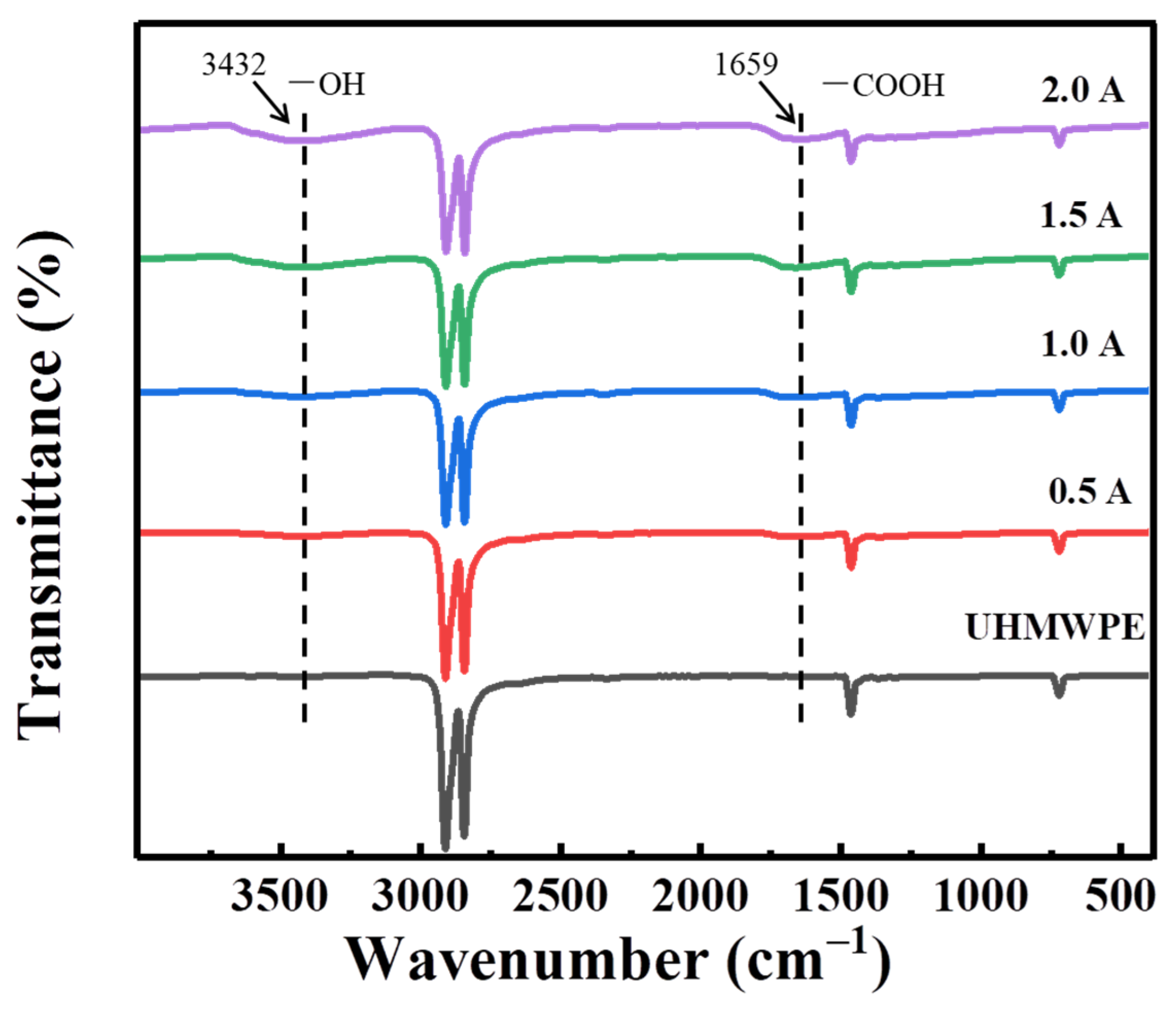
The FTIR of UHMWPE substrates treated with different carbon plasma currents with the wavenumber range of 4000–400 cm−1 are shown in Figure 1. The main infrared absorption peak wavenumbers of UHMWPE are about 2912, 2844, 1464 and 722 cm−1, which respectively represent the asymmetric stretching vibration of methylene, the symmetric stretching vibration of methylene, the bending vibration of methylene, and the rocking vibration of methylene. The intensities of the characteristic peaks of the UHMWPE substrates gradually decrease with the increase of the carbon plasma treatment current, while new characteristic peaks appear at wavelengths 3432 and 1659 cm−1, corresponding to the hydroxyl and carboxyl groups, respectively. The appearance of these polar groups may be due to the carbon plasma bombarding the macromolecular chain on the UHMWPE surface, resulting in the formation of an active polymer chain, which reacts with residual oxygen [23,24,25]. The large number of polar groups generated continues to increase with the treatment current. The results show the peak intensity peaks of hydroxyl and carboxyl groups increase in the infrared spectrum.
3.2. Raman Spectroscopy
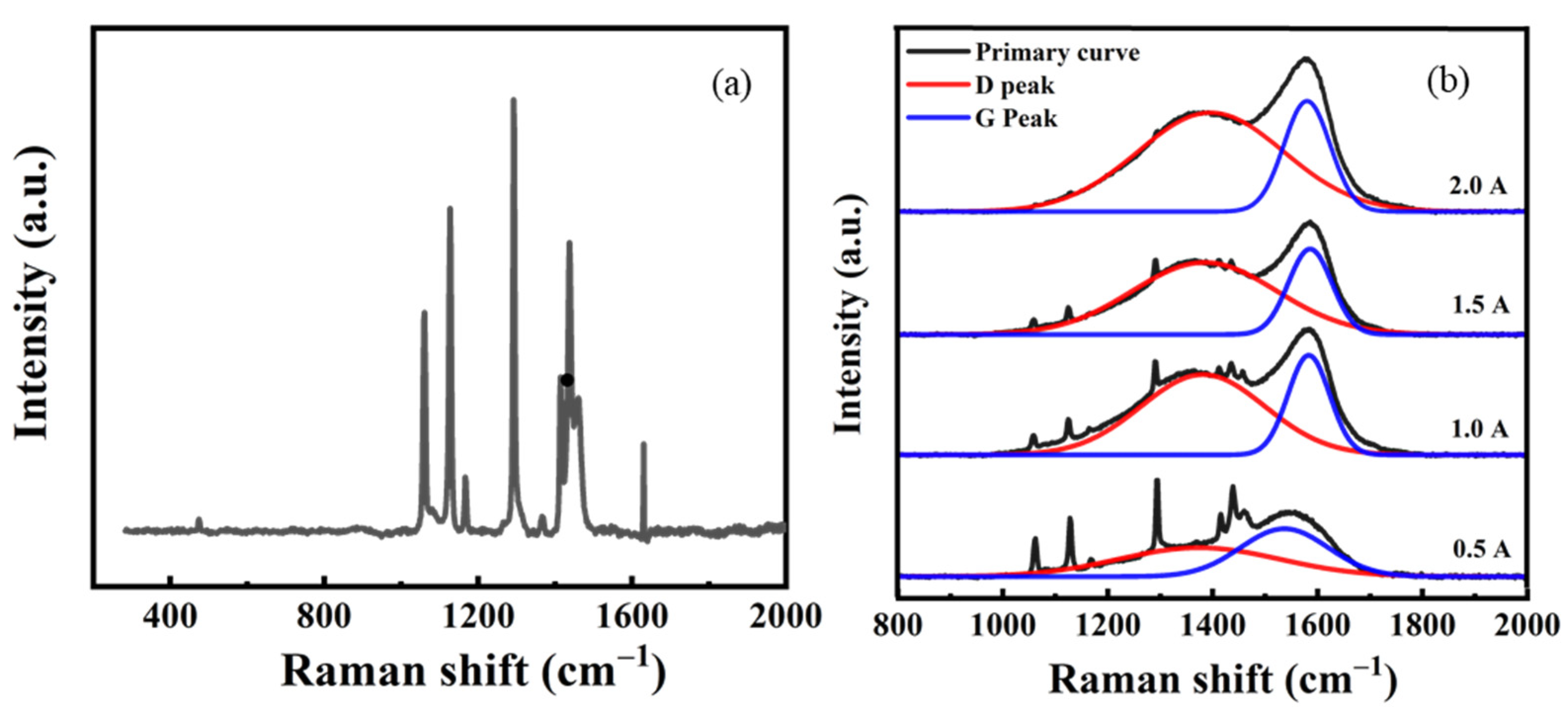
Raman spectroscopy is considered to be an effective method for analyzing carbon structure [26,27]. Figure 2 shows the Raman spectra of the UHMWPE substrates and the Raman spectra of the UHMWPE substrates treated with different carbon plasma currents. It can be clearly observed from the figure that the Raman characteristic vibration types of the UHMWPE substrates are mainly C–C stretching vibration, –CH2 shear vibration, –CH2 curling vibration, etc. As the current increases, the peak intensity gradually weakens, and the intensity of the characteristic peaks of the a-C films gradually increases. Only the characteristic peaks of a-C exist in the system when increasing the carbon plasma treatment current to 2.0 A. The results indicate that the organic carbonaceous structure can change to an inorganic amorphous carbonaceous structure increasing treatment current.
The Raman spectrum of UHMWPE substrates treated with different carbon plasma currents is fitted to two peaks by Gaussian function. The two peaks are located at around 1380 cm−1 of the D Peak and 1580 cm−1 of the G Peak, respectively [28]. The D Peak is attributed to modes of the sp2 sites in the six-fold rings, while the G Peak is due -to the tensile vibration of all of the paired sp2 sites in the six-membered ring and the carbon chain [29]. The intensity ratios of the D peak and the G peak are closely related to the content of sp2 carbon and sp3 carbon in the a-C structure [30]. The ratio value of ID/IG is related to the content of sp2. Higher ID/IG ratios indicate the presence of more sp2 carbon structures in the a-C [21,28,30]. Table 3 shows the position and FHWM of the D peak and the G peak, as well as the ID/IG ratio values of UHMWPE substrates treated with different carbon plasma currents. The positions of the D and G Peaks gradually shift to higher wavenumbers, and the ID/IG value ratio gradually increases from 0.97 to 2.83, when increasing the treatment current from 0.5 to 2.0 A. This indicates that a-C films fabricated on UHMWPE substrates form more sp2 carbon structures in the system with increasing carbon plasma treatment current.
3.3. XPS Spectra
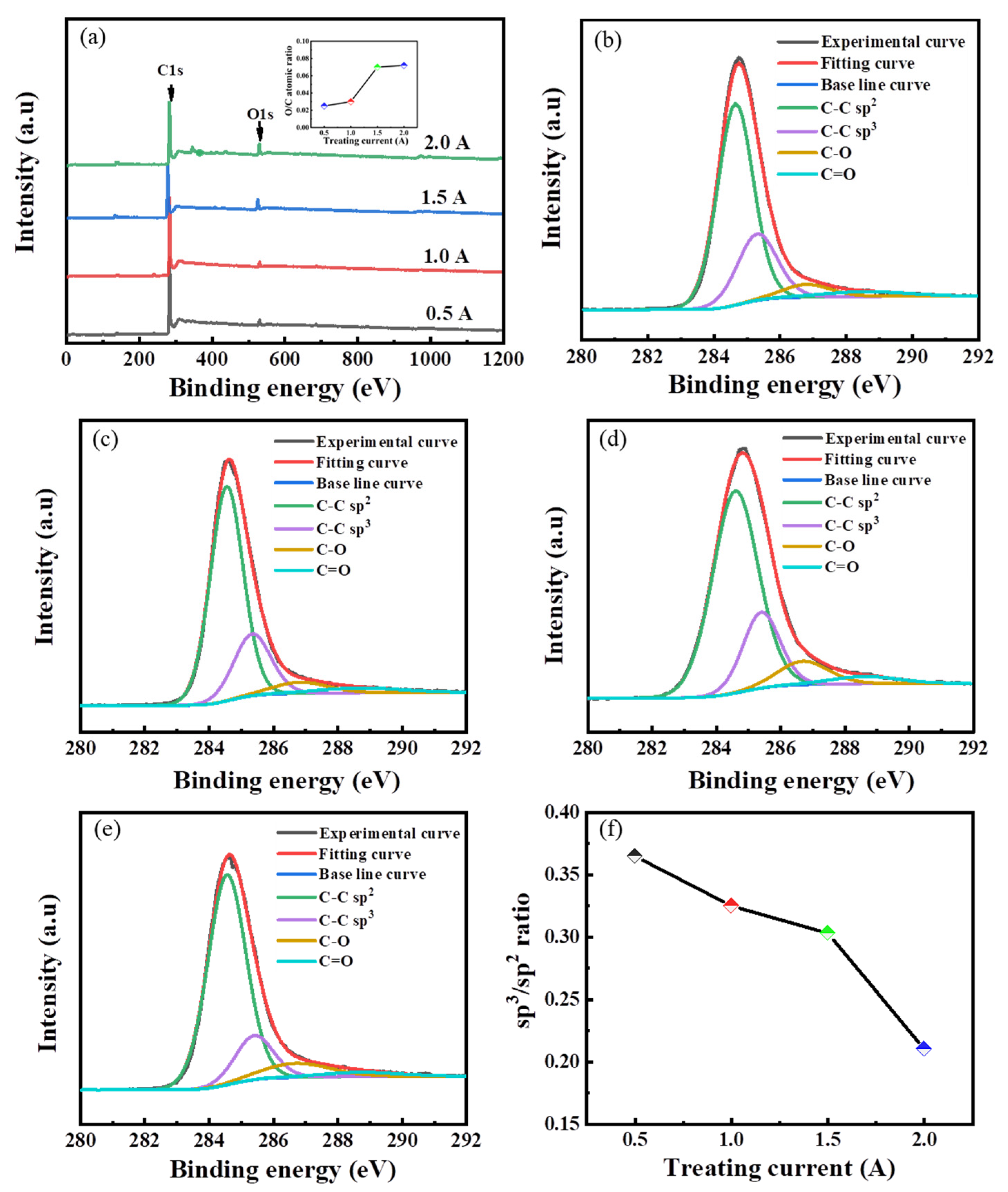
Figure 3a shows the wide XPS spectra of UHMWPE substrates treated with different carbon plasma currents. It can be clearly seen that there are two obvious peaks at 284.8 and 532.8 eV, Corresponding to C1s and O1s, respectively. The O/C atomic ratio value is shown in the inserted picture. With the increase in the carbon plasma treatment current, the increasing value of O/C ratio leads to the emergence of new oxygen-containing groups [31], which is in agreement with the FTIR results. The treatment with currents of 0.5 A (Figure 3b), 1.0 A (Figure 3c), 1.5 A (Figure 3d) and 2.0 A (Figure 3e) indicated that the C1s spectrum fits to four peaks at around 284.6, 285.3, 286.7, and 288.6 eV, which are assigned to sp2 C–C, sp3 C–C, C–O and C=O, respectively [32,33]. The appearance of C–O and C=O peaks is in agreement with the FTIR results. In addition, Figure 3f gives the sp3/sp2 ratio values of UHMWPE substrates treated with different carbon plasma currents. It can be observed that the sp3/sp2 ratio value decreases with increasing treatment current, which is in agreement with the Raman spectra results. This is probably because the carbon plasma current continuously bombards the UHMWPE surface, resulting in the formation of a large number of sp2 clusters [34].
3.4. Surface Morphology
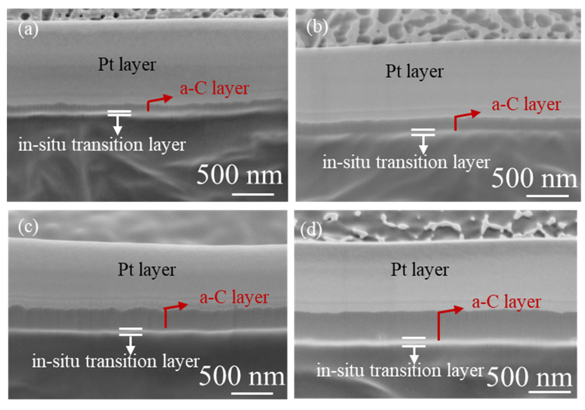
Figure 4 and Figure 5 show the surface and cross-section morphologies of UHMWPE treated with different carbon plasma currents, respectively. For Figure 4, the surface morphologies of a-C films present an island-shaped structure, which is correlated with the strong bombardment by high-energy particles during magnetron sputtering [21]. White particles can be observed on the surface with a carbon plasma treatment current of 0.5 A. The white particles disappear, and the island-shaped structures become dense, when the carbon plasma current is increased to 2.0 A. These white particles may belong to the segments resulting from the breaking of the macromolecular chains of the UHMWPE surface when bombarded by high-energy carbon particles. For Figure 5, a Pt layer was added on the as-fabricated a-C films in order to avoid the energetic ion beam and improve conductivity. In addition, an in situ transition layer can clearly be observed. The thickness of the a-C and transition layers becomes thicker with increasing carbon plasma treatment current.
3.5. Growth Mechanism of a-C Film on the UHMWPE Substrate
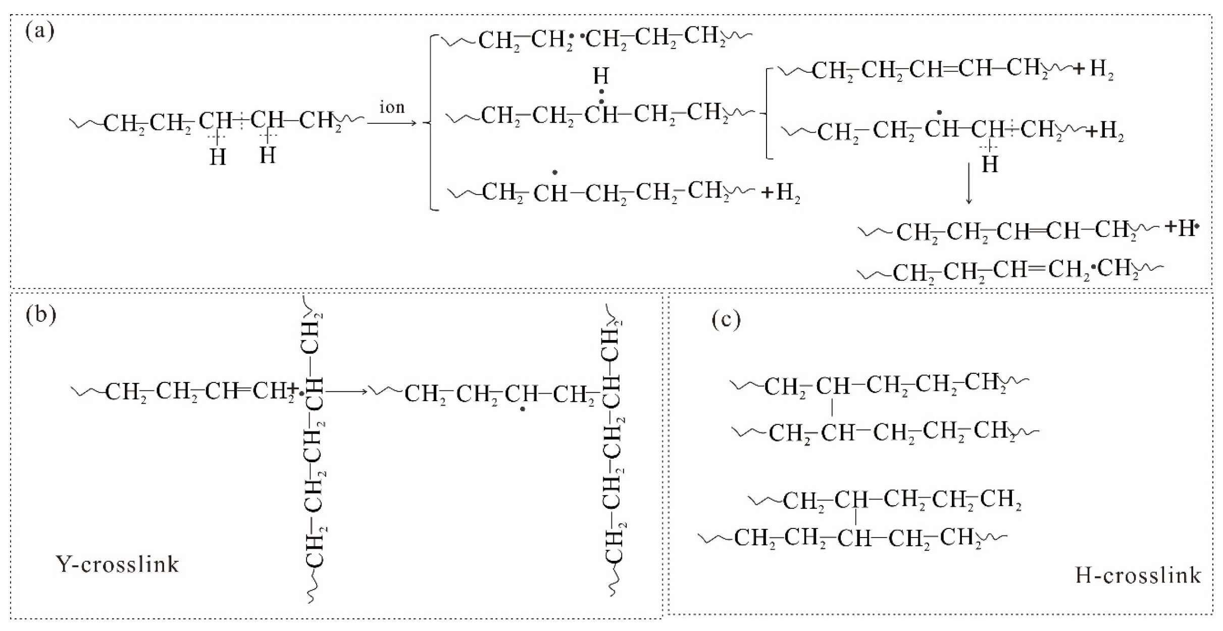
On the basis of the above characterization analysis, we concluded that the growth mechanism of a-C film on the UHMWPE substrate includes three aspects, as shown in Figure 6. Firstly, argon plasma generated by glow discharge continuously bombards the graphite target, sputtering carbon plasma. The carbon plasma bombards the UHMWPE surface (Figure 6a) under the action of the electric field to activate its surface. The series of chemical reactions after activation are shown in Figure 7. The C–C bond and C–H bond of the UHMWPE surface randomly break when bombarded with carbon plasma energy [18], resulting in a series of different products, as shown in Figure 7a, including hydrogen radicals, secondary carbon radicals, tertiary carbon radicals, chains with different molecular weights, some allyl fragments, etc. Then, a series of complex reactions occurs among the carbon radicals and the different products under the continuous bombardment of the treatment current. One is that the active chains of the UHMWPE surface form Y crosslinks and H crosslinks [35]. These structures are presented in Figure 7b,c. The other aspect is that carbon radicals react with active chains of the UHMWPE surface to form a composite structure of organic–inorganic chains, while carbon–carbon radicals also react to produce amorphous carbon chains that do not contain hydrogen. In addition, active chains with low molecular weight overflowing from the UHMWPE surface react with other active chains or carbon radicals. These results are shown in Figure 6b. Finally, the formed crosslinked structures act as a barrier to prevent continued overflow of the active chains of the UHMWPE surface. The crosslinked structures reach a certain level following continuous bombardment with carbon plasma; there will be no overflow of active chains from the UHMWPE surface, and only existing carbon plasma will interact in the system. Carbon plasma continues its epitaxial growth, forming amorphous carbon chains, as shown in Figure 6c. From the above mechanism analysis, it can be concluded that a-C film grown in situ on the UHMWPE substrates include an in situ transition layer and an epitaxial growth layer. The in situ transition layer, which contains a composite structure of inorganic amorphous and organic carbon chains, forms between the UHMWPE substrates and the a-C film. It can be seen from the cross-section analysis that the thicknesses of the in situ transition layer and the epitaxial growth layer increase with the increase of the treatment current.
3.6. Contact Angle
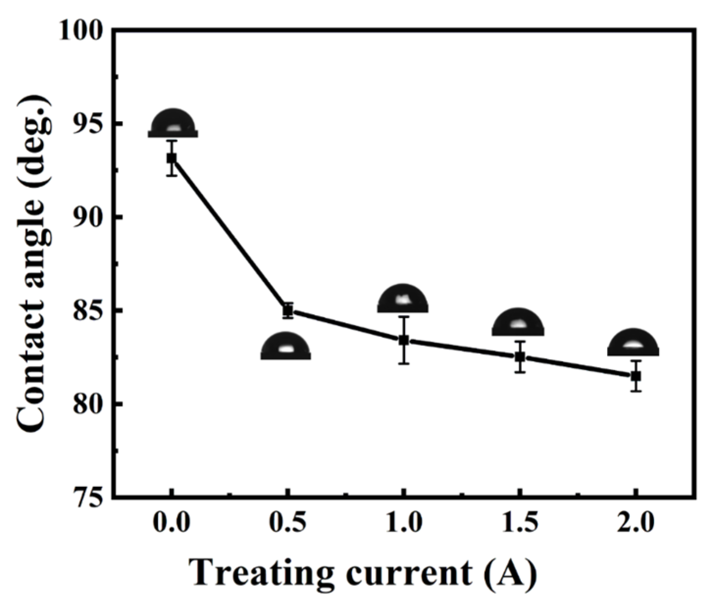
Figure 8 illustrates the contact angle of UHMWPE substrates treated with different carbon plasma currents under deionized water in an atmosphere environment. The results show that the contact angle of the original UHMWPE is about 93.2°, and the contact angle decreases from 85.0° at 0.5 A to 81.5° at 2.0 A with increasing treatment current. The reduction of the contact angle may be caused by polar groups, which is consistent with XPS and FTIR spectroscopy. The presence of polar groups increases the hydrophilicity of the samples [25,36].
3.7. Mechanism Properties
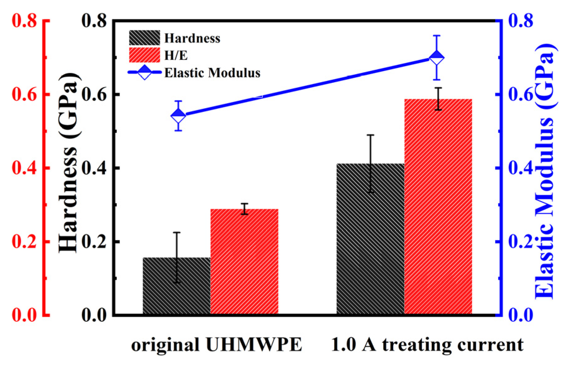
Hardness is an important parameter for evaluating the mechanical properties and abrasion resistance of hard carbon-based films. Hardness–elasticity ratio is an important parameter for evaluating the durability, compressive resistance and plastic deformation of coatings [37]. We conducted nano-hardness tests at 0.5 A, 1.0 A and 1.5 A, and found that in situ growth amorphous carbon films increased the hardness of the UHMWPE surface. Here, we take the larger error as an example. Figure 9 shows the hardness, elastic modulus and hardness–elasticity ratio of the UHMWPE substrate treated with carbon plasma of 1.0 A. The results indicate that the mechanical properties of the UHMWPE substrate treated with carbon plasma of 1.0 A were promoted compared with the original UHMWPE.
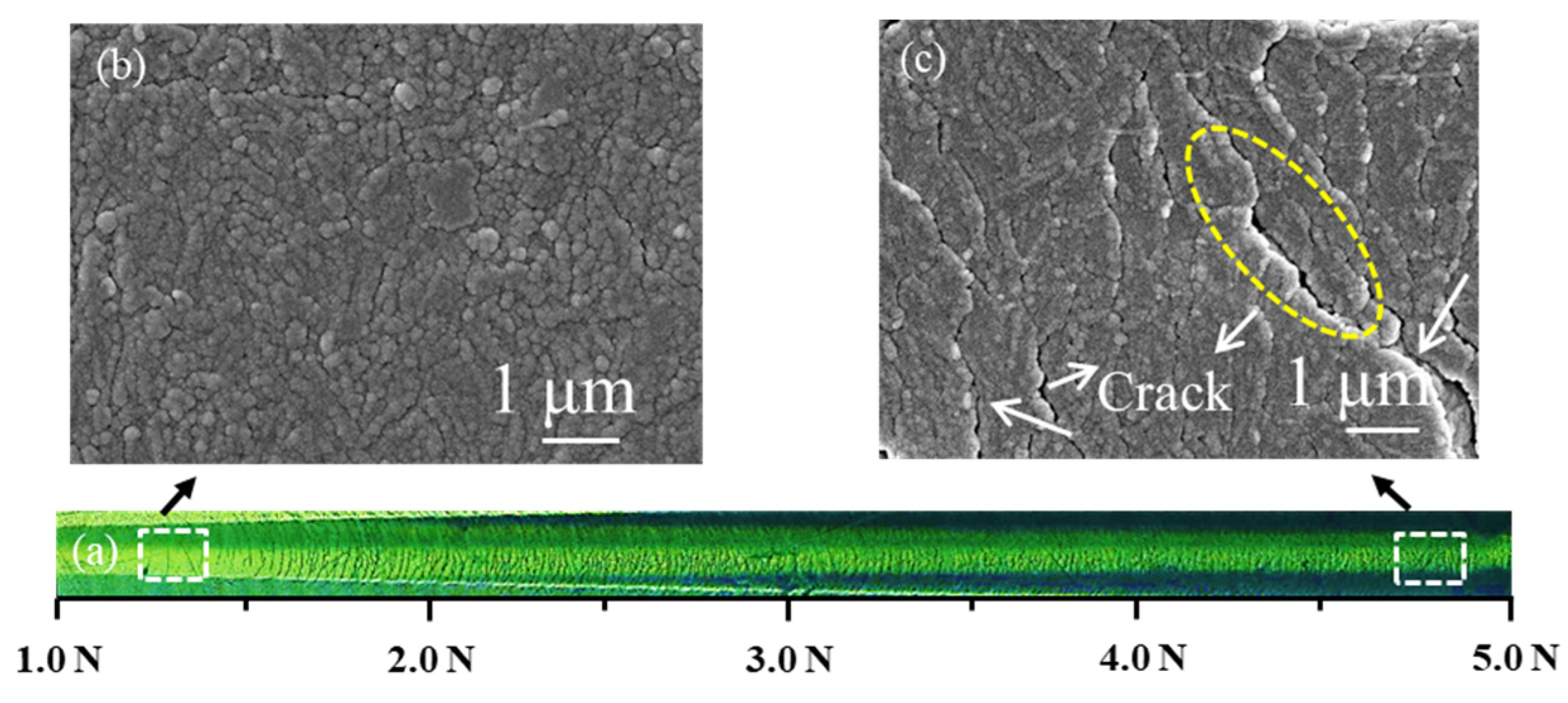
Insufficient film-base bonding strength restricts the application of the UHMWPE in many fields, so it is necessary to study adhesive strength between the UHMWPE substrate and the a-C film. The results of the scratch test of the UHMWPE substrate treated with carbon plasma of 1.0 A are shown in Figure 10. We selected the area with small loads and the area with large loads on the scratch surface, respectively. Then, SEM was applied to observe the morphologies of these two areas. It can be seen from Figure 10b,c that the scratch surface exhibited a small change in the area with small loading force, with the crack area and the crack becoming larger with increasing loading force, but the peeling phenomenon of the a-C film was rarely found in the scratch area. The cracking phenomenon appears without peeling. This indicates that in the situ transition layer in the form of chemical bonds provides strong adhesion between the a-C film and the UHMWPE substrate, resulting in superior protection.
3.8. Tribological Performances
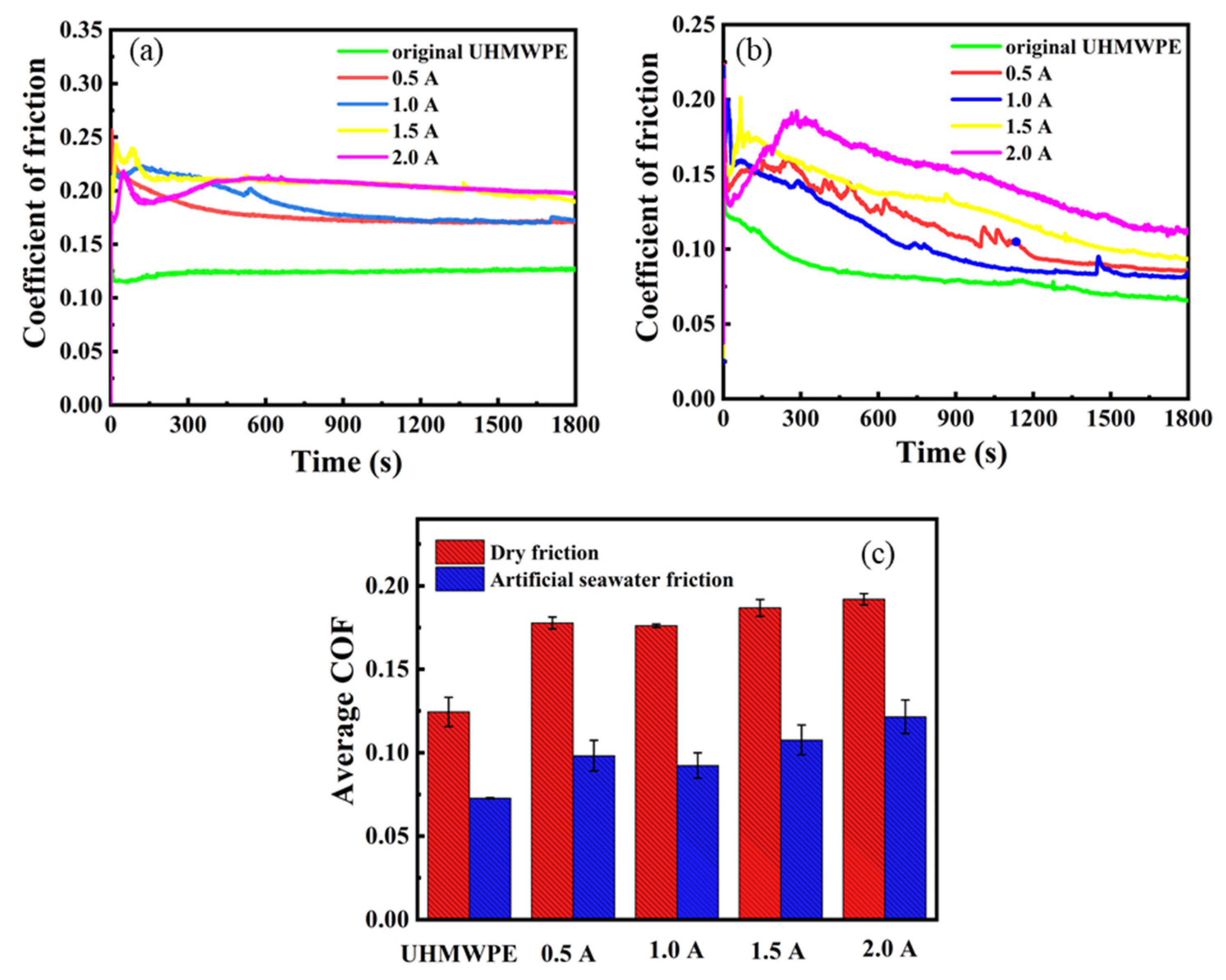
Figure 11 shows the evolution of the friction coefficient of the UHMWPE substrates treated with different carbon plasma currents sliding against 304 stainless steel balls under dry and artificial seawater friction. As shown in Figure 11a. When the current is 0.5 and 1.0 A, the friction coefficient curve decreases and tends to be stable with the progress of the wear process. When the current is 2.0 A, the friction coefficient curve suddenly rises, indicating serious wear. It can be seen from Figure 11c that the original UHMWPE shows a low average COF (coefficient of friction) of 0.125. The samples treated with carbon plasma exhibit slightly higher average COF. The reason for this may be that the molecular structure of the UHMWPE surface is linear and the intermolecular force is weak. Under the action of the loading force, the linear structure is easily destroyed, resulting in poor wear resistance and a low friction coefficient. Frictional heat induces graphitization at the surface of the a-C film during friction [21]. Both materials have a self-lubricating mechanism, but their self-lubricating mechanisms are different. The viscosity caused by deformation of the UHMWPE substrate under loading force increases the friction coefficient of the a-C film. Although the a-C films exhibit self-lubricating properties on a hard substrate [38,39], they exhibit a slightly higher friction coefficient on the UHMWPE substrate. The average COF of the UHMWPE substrates treated with different carbon plasma currents slightly decreases from 0.178 at 1.0 A to 0.176 at 0.5 A, with the average COF continuously increasing to 0.192 under 2.0 A.
Figure 11b shows the friction coefficient curve under the artificial seawater environment. The friction coefficient curve of the original UHMWPE and the UHMWPE substrates treated with different carbon plasma currents exhibits a downward trend with the progress of the wear process. When the current is 2.0 A, the friction coefficient curve sharply increases in the initial stage, indicating that friction and wear are more serious at this stage. The friction coefficient decreases after running-in. Figure 11c shows the average COF values of the UHMWPE substrates treated with different carbon plasma currents under the artificial seawater environment, which are 0.072 (original UHMWPE), 0.098 (0.5 A), 0.092 (1.0 A), 0.107 (1.5 A), and 0.122 (2.0 A), respectively. The water film has a lubricating effect, but it is difficult to form a continuous water film under the contact conditions of this experiment. The experiment simulates the state of semi-dry friction or boundary lubrication. The microscopic scale of the friction contact surface includes water film lubrication and a solid–solid contact area. The a-C film has good self-lubricating properties, and its self-lubricating mechanism is different from that of UHMWPE. Due to the viscosity caused by the deformation of the substrates under the action of the loading force, the friction coefficient of the a-C film increases. Therefore, the entire material system still exhibits a slightly higher friction coefficient on the UHMWPE substrate.
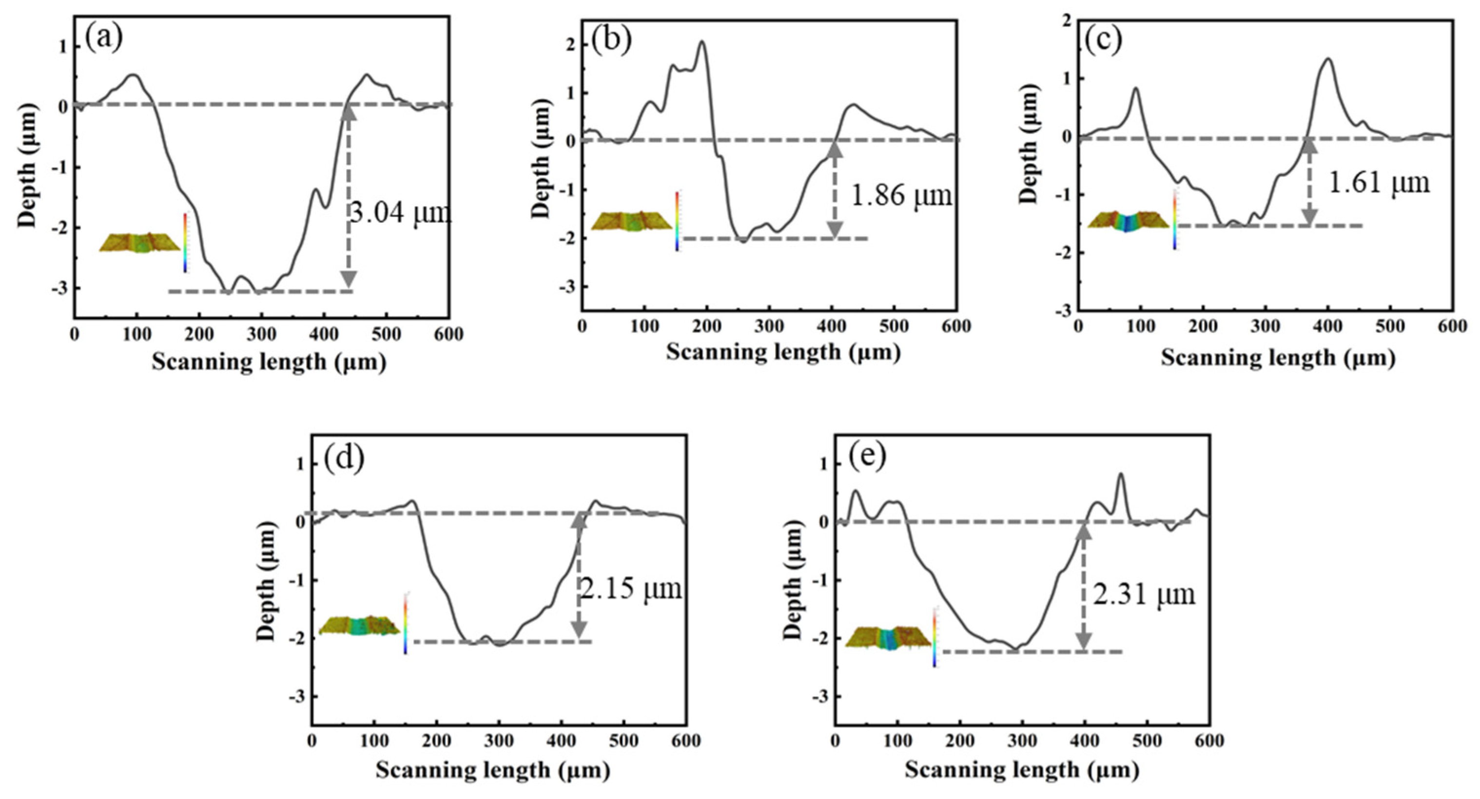
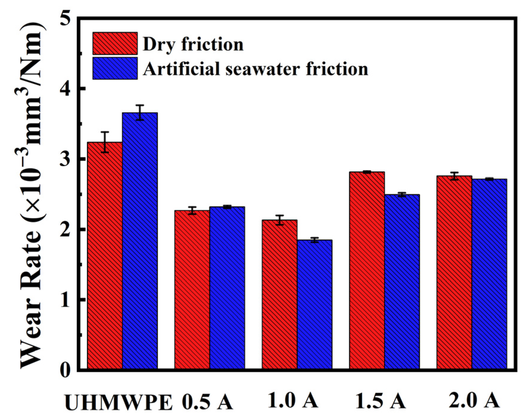
The cross-section profiles and three-dimensional (3D) micrographs of the worn track UHMWPE substrates treated with different carbon plasma currents under dry and artificial seawater friction are shown in Figure 12 and Figure 13, respectively. It can be concluded from the 3D profile that the roughness of the UHMWPE substrate is 0.31 μm, and the roughness of the a-C films prepared under currents of 0.5 A, 1.0 A, 1.5 A and 2.0 A is 0.57 μm, 0.71 μm, 0.89 μm, 1.33 μm, respectively. From these data, it can be concluded that the roughness of the sample after carbon plasma treatment increases, leading to an increase in friction. Compared with UHMWPE substrates, the coefficient of friction is increased. At the same time, the increase in roughness also leads to an increase in the wettability of the sample, resulting in a decrease in the contact angle, which is consistent with the measurement results for the contact angle. It can be observed that the UHMWPE substrate treated with carbon plasma current of 1.0 A exhibits a lower wear depth under dry friction conditions (1.81 μm) and the artificial seawater environment (1.61 μm). By integrating the worn track and calculation profiles, the wear rate value of the samples under the two environments are shown in Figure 14. Whether under dry friction or artificial seawater friction, UHMWPE has the most severe wear rate, reaching as high as 3.24 × 10⁻⁵ and 3.66 × 10⁻⁵ mm3/Nm, respectively. The wear rate values of the samples under dry friction are about 2.26 × 10⁻⁵ (0.5 A), 2.13 × 10⁻⁵ (1.0 A), 2.81 × 10⁻⁵ (1.5 A), 2.75 × 10⁻⁵ mm3/Nm (2.0 A). The wear rate values of the samples under artificial seawater friction are about 2.32 × 10⁻⁵ (0.5 A), 1.85 × 10⁻⁵ (1.0 A), 2.49 × 10⁻⁵ (1.5 A), 2.71 × 10⁻⁵ mm3/Nm (2.0 A). Because artificial seawater has a good lubrication effect [6], the average COF under artificial seawater conditions is lower than under dry conditions, with the wear rate for artificial seawater friction decreasing relative to the dry friction. The wear rate of the UHMWPE substrate treated using carbon plasma of 1.0 A exhibits values 1.5 times and 2.0 times lower than the original UHMWPE under dry friction and artificial seawater friction, respectively.
The UHMWPE substrate treated with carbon plasma of 1.0 A presents excellent tribological performances under the two friction environments, so the surface morphologies of the wear track under the two friction environments are shown in Figure 15. It can be clearly seen from Figure 15a,b that small particles appear on the surface of the wear track, which was mainly due to the existence of abrasive wear and adhesive wear of the two materials after friction under the two environments. At the same time, it was observed that the irregular fragments and tiny crack phenomena appear on the surface of the UHMWPE under dry friction and artificial seawater friction, respectively. However, the a-C film rarely peels away from the UHMWPE substrate, indicating that the presence of the in situ transition layer provides reliable adhesion between the a-C film and the UHMWPE substrate. The epitaxial growth layer of a-C based on the in situ transition layer acts as a contact surface for the grinding ball, so the depth of the wear is shallower than the original UHMWPE under the two friction environments. Under the action of the friction load, the UHMWPE substrate is prone to plastic deformation, the hard a-C film generates irregular fragments due to the plastic deformation of the substrate, protecting the UHMWPE substrate with strong adhesion under dry friction. Under artificial seawater friction, seawater plays a role in lubrication and cooling, causing tiny cracks with strong adhesion to appear during wear. Therefore, good protection is achieved during sliding wear under the two environments. The good protection mechanism with strong adhesion is shown in Figure 16, preventing the severe wear of the UHMWPE substrate during sliding.
4. Conclusions
a-C film of different thicknesses was successfully prepared on a UHMWPE substrate using different carbon plasma current treatments. The microstructure, growth mechanism, wettability, mechanical properties, and tribological properties of the a-C films prepared on the UHMWPE substrates were studied. The main conclusions can be drawn as follows. (1) As the carbon plasma current increased, more sp2-C content was formed in the system. (2) An in situ growth mechanism for the a-C film on UHMWPE substrate was proposed. (3) The results of the contact angle test showed that the a-C films improved the wetting performance of the UHMWPE substrates. (4) The in situ transition layer formed during the in situ growth process improved the adhesive strength of the film-base, thereby improving the mechanical properties of the UHMWPE substrates. (5) The reliable adhesive strength of the film-base ensured that the a-C film, which has excellent wear resistance, plays a major role at the surface of the substrate. Among these, the wear rate of the UHMWPE treated with 1.0 A carbon plasma current was reduced by 1.5 times and 2.0 times with respect to the two friction environments, respectively. In general, this work provided a new way of broadening the application of polymer materials in many respects.
Author Contributions
Conceptualization, D.P. and B.X.; supervision, S.Z.; methodology; L.M; writing—review and editing, R.D.; Writing-review and editing, L.M. and S.Z.; investigation, R.D., D.P. and B.X. All authors have read and agreed to the published version of the manuscript.
Funding
This research was funded by the National Natural Science Foundation of China (Grant No. 51975563).
Institutional Review Board Statement
Not applicable.
Informed Consent Statement
Not applicable.
Data Availability Statement
Data are contained within the article.
Acknowledgments
The authors are thankful for financial support of the National Natural Science Foundation of China (Grant No. 51975563).
Conflicts of Interest
The authors declare no conflict of interest.
References
- Wu, Y.M.; Jiang, F.W.; Qiang, Y.J.; Zhao, W.J. Synthesizing a novel fluorinated reduced graphene oxide-CeO2 hybrid nanofiller to achieve highly corrosion protection for waterborne epoxy coatings. Carbon 2021, 176, 39–51. [Google Scholar] [CrossRef]
- Wu, Y.M.; Zhao, W.J.; Qiang, Y.J.; Chen, Z.J.; Wang, L.P.; Gao, X.L.; Fang, Z.W. π-π interaction between fluorinated reduced graphene oxide and acridizinium ionic liquid: Synthesis and anti-corrosion application. Carbon 2020, 159, 292–302. [Google Scholar] [CrossRef]
- Abdul-Kader, A.M. Photoluminescence and optical properties of He ion bombarded ultra-high molecular weight polyethylene. Appl. Surf. Sci. 2009, 255, 5016–5020. [Google Scholar] [CrossRef]
- Chen, J.S.; Zhu, F.Y.; Pan, H.C.; Cao, J.Q.; Zhu, D.Z.; Xu, H.J.; Qiang, C.; Shen, J.G.; Chen, L.H.; He, Z.R. Surface modification of ion implanted ultra high molecular weight polyethylene. Nucl. Instrum. Methods Phys. Res. Sect. B Beam Interact. Mater. At. 2000, 169, 26–30. [Google Scholar] [CrossRef]
- Chen, B.B.; Wang, J.Z.; Yan, F.Y. Friction and Wear Behaviors of Several Polymers Sliding Against GCr15 and 316 Steel Under the Lubrication of Sea Water. Tribol. Lett. 2011, 42, 17–25. [Google Scholar] [CrossRef]
- Pang, W.C.; Ni, Z.F.; Wu, J.L.; Zhao, Y.W. Investigation of tribological properties of graphene oxide reinforced ultrahigh molecular weight polyethylene under artificial seawater lubricating condition. Appl. Surf. Sci. 2018, 434, 273–282. [Google Scholar] [CrossRef]
- Wang, Y.Z.; Yin, Z.W.; Li, H.L.; Gao, G.Y.; Zhang, X.L. Friction and wear characteristics of ultrahigh molecular weight polyethylene (UHMWPE) composites containing glass fibers and carbon fibers under dry and water-lubricated conditions. Wear 2017, 380–381, 42–51. [Google Scholar] [CrossRef]
- Shi, W.; Dong, H.; Bell, T. Wear performance of ion implanted ultra high molecular weight polyethylene. Surf. Eng. 2003, 19, 279–283. [Google Scholar] [CrossRef]
- Valenza, A.; Visco, A.M.; Torrisi, L.; Campo, N. Characterization of ultra-high-molecular-weight polyethylene (UHMWPE) modified by ion implantation. Polymer 2004, 45, 1707–1715. [Google Scholar] [CrossRef]
- Zhang, J.; Wang, Y.; Zhou, S.; Wang, Y.; Wang, C.; Guo, W.; Lu, X.; Wang, L. Tailoring self-lubricating, wear-resistance, anticorrosion and antifouling properties of Ti/(Cu, MoS2)-DLC coating in marine environment by controlling the content of Cu dopant. Tribol. Int. 2020, 143, 106029. [Google Scholar] [CrossRef]
- Donnet, C. Recent progress on the tribology of doped diamond-like and carbon alloy coatings: A review. Surf. Coat. Technol. 1998, 100, 180–186. [Google Scholar] [CrossRef]
- Donnet, C.; Grill, A. Friction control of diamond-like carbon coatings. Surf. Coat. Technol. 1997, 94–95, 456–462. [Google Scholar] [CrossRef]
- Wang, Y.J.; Li, H.X.; Ji, L.; Liu, X.H.; Wu, Y.X.; Zhou, H.D. Superior tribological properties of an amorphous carbon film with a graphite-like structure. Chin. Phys. B 2012, 21, 320–328. [Google Scholar] [CrossRef]
- Ferrari, A.C.; Robertson, J. Interpretation of Raman spectra of disordered and amorphous carbon. Phys. Rev. B 2000, 61, 14095–14107. [Google Scholar] [CrossRef] [Green Version]
- Shi, X.L.; Wang, Q.L.; Xu, L.L.; Ge, S.R.; Wang, C. Hydrogenated diamond-like carbon film deposited on UHMWPE by RF-PECVD. Appl. Surf. Sci. 2009, 255, 8246–8251. [Google Scholar] [CrossRef]
- Michler, T.; Grischke, M.; Bewilogua, K.; Dimigen, H. Properties of duplex coatings prepared by plasma nitriding and PVD Ti–C:H deposition on X20Cr13 ferritic stainless steel. Thin Solid Films 1998, 322, 206–212. [Google Scholar] [CrossRef]
- Akovalı, G. (Ed.) The Interfacial Interactions in Polymeric Composites; Springer: Berlin/Heidelberg, Germany, 1993; Volume 230, pp. 9–17. [Google Scholar]
- Liston, E.M. Plasma Treatment for Improved Bonding—A Review. J. Adhes. 1989, 30, 199–218. [Google Scholar] [CrossRef]
- Egitto, F.D.; Matienzo L, J. Plasma Modification of Polymer Surfaces for Adhesion Improvement. IBM J. Res. Dev. 1994, 38, 423–439. [Google Scholar] [CrossRef]
- Baba, K.; Hatada, R. Deposition of diamond-like carbon films on polymers by plasma source ion implantation. Thin Solid Films 2006, 506, 55–58. [Google Scholar] [CrossRef]
- He, F.F.; Bai, W.Q.; Li, L.L.; Wang, X.L.; Xie, Y.J.; Jin, G.; Tu, J.P. Enhancement of adhesion by a transition layer: Deposition of a-C film on ultrahigh molecular weight polyethylene (UHMWPE) by magnetron sputtering. Appl. Surf. Sci. 2016, 364, 280–287. [Google Scholar] [CrossRef]
- Jacob, W.; Moller, W. On the Structure of Thin Hydrocarbon Films. Appl. Phys. Lett. 1993, 63, 1771–1773. [Google Scholar] [CrossRef]
- Guruvenket, S.; Rao, G.M.; Komath, M. Raichur AM. Plasma surface modification of polystyrene and polyethylene. Appl. Surf. Sci. 2004, 236, 278–284. [Google Scholar] [CrossRef] [Green Version]
- Svorcik, V.; Kotal, V.; Slepicka, P.; Blahova, O.; Spirkova, M.; Sajdl, P. Modification of surface properties of polyethylene by Ar plasma discharge. Nucl. Instrum. Meth. B Beam Interact. Mater. At. 2006, 244, 365–372. [Google Scholar] [CrossRef]
- Svorcik, V.; Kolarova, K.; Slepicka, P.; Mackova, A.; Novotna, M.; Hnatowicz, V. Modification of surface properties of high and low density polyethylene by Ar plasma discharge. Polym. Degrad. Stabil. 2006, 91, 1219–1225. [Google Scholar] [CrossRef]
- Ferrari, A.C.; Robertson, J. Raman spectroscopy of amorphous, nanostructured, diamond-like carbon, and nanodiamond. Philos. Trans. R. Soc. Lond. Ser. A Math. Phys. Eng. Sci. 2004, 362, 2477–2512. [Google Scholar] [CrossRef] [PubMed]
- Osada, M.; Kakihana, M. Application of Raman spectroscopy to characterization of carbon-based materials Recent advances and their applications to nano-carbons. TANSO 2007, 228, 174–184. [Google Scholar] [CrossRef]
- Dhandapani, V.S.; Subbiah, R.; Thangavel, E.; Arumugam, M.; Park, K.; Gasem, Z.M. Tribological properties, corrosion resistance and biocompatibility of magnetron sputtered titanium-amorphous carbon coatings. Appl. Surf. Sci. 2016, 371, 262–274. [Google Scholar] [CrossRef]
- Robertson, J. Properties of Diamond-Like Carbon. Surf. Coat. Technol. 1992, 50, 185–203. [Google Scholar] [CrossRef]
- Zhang, J.W.; Zhou, S.G.; Wang, Y.X.; Wang, Y.C.; Wang, C.T.; Lu, X. Enhancing anti-corrosion and antifouling properties of Cu/GLC composite film for marine application. Surf. Coat. Technol. 2019, 375, 414–426. [Google Scholar] [CrossRef]
- Yang, L.Q.; Chen, J.R.; Guo, Y.F.; Zhang, Z. Surface modification of a biomedical polyethylene terephthalate (PET) by air plasma. Appl. Surf. Sci. 2009, 255, 4446–4451. [Google Scholar] [CrossRef]
- Xie, D.; Liu, H.J.; Deng, X.R.; Leng, Y.X.; Huang, N. Deposition of a-C:H films on UHMWPE substrate and its wear-resistance. Appl. Surf. Sci. 2009, 256, 284–288. [Google Scholar] [CrossRef]
- Wu, Y.M.; Zhao, W.J.; Lu, Z.B.; Wang, L.P. Fluorinated graphene film for corrosion control on copper: Experimental and theoretical studies. Carbon 2021, 179, 445–457. [Google Scholar] [CrossRef]
- Wang, Y.J.; Li, H.X.; Ji, L.; Zhao, F.; Kong, Q.H.; Wang, Y.X. Microstructure, mechanical and tribological properties of graphite-like amorphous carbon films prepared by unbalanced magnetron sputtering. Surf. Coat. Technol. 2011, 205, 3058–3065. [Google Scholar] [CrossRef]
- Luigi, C.; Bracco, P. Mechanisms of Crosslinking and Oxidative Degradation of UHMWPE; William Andrew Publishing: Norwich, NY, USA, 2004; Volume 11, pp. 245–261. [Google Scholar]
- Bui, X.L.; Pei, Y.T.; Mulder, E.; Hosson, J. Adhesion improvement of hydrogenated diamond-like carbon thin films by pre-deposition plasma treatment of rubber substrate. Surf. Coat. Technol. 2009, 203, 1964–1970. [Google Scholar] [CrossRef] [Green Version]
- Zhang, S.D.; Yan, M.F.; Yang, Y.; Zhang, Y.X.; Yan, F.Y.; Li, H.T. Excellent mechanical, tribological and anti-corrosive performance of novel Ti-DLC nanocomposite thin films prepared via magnetron sputtering method. Carbon 2019, 151, 136–147. [Google Scholar] [CrossRef]
- Wang, J.J.; Cao, X.Q.; Lu, Z.B.; Zhang, G.G.; Xue, Q.J. The improved mechanical and tribological properties of amorphous carbon film by doping boron carbide. Ceram. Int. 2020, 46, 9878–9884. [Google Scholar] [CrossRef]
- Erdemir, A.; Donnet, C. Tribology of diamond-like carbon films: Recent progress and future prospects. J. Phys. D Appl. Phys. 2006, 39, R311–R327. [Google Scholar] [CrossRef]
Figure 1.
FTIR of UHMWPE substrates treated with different carbon plasma currents.

Figure 2.
(a) Raman spectra of UHMWPE substrates, (b) Raman spectra of UHMWPE substrates treated with different carbon plasma currents.
Figure 2.
(a) Raman spectra of UHMWPE substrates, (b) Raman spectra of UHMWPE substrates treated with different carbon plasma currents.

Figure 3.
XPS of UHMWPE substrates treated with different carbon plasma currents: (a) wide XPS spectrum (the inserted picture is the atomic ratio of O/C), (b–e) the fitting results of the C1s spectrum with treatment currents of 0.5, 1.0, 1.5 and 2.0 A, respectively, (f) the sp3/sp2 ratio value.
Figure 3.
XPS of UHMWPE substrates treated with different carbon plasma currents: (a) wide XPS spectrum (the inserted picture is the atomic ratio of O/C), (b–e) the fitting results of the C1s spectrum with treatment currents of 0.5, 1.0, 1.5 and 2.0 A, respectively, (f) the sp3/sp2 ratio value.

Figure 4.
SEM morphologies of UHMWPE substrates treated with different carbon plasma currents: (a) 0.5 A, (b) 1.0 A, (c) 1.5 A, (d) 2.0 A.
Figure 4.
SEM morphologies of UHMWPE substrates treated with different carbon plasma currents: (a) 0.5 A, (b) 1.0 A, (c) 1.5 A, (d) 2.0 A.

Figure 5.
Cross-section morphologies of UHMWPE substrates treated with different carbon plasma currents: (a) 0.5 A, (b) 1.0 A, (c) 1.5 A, (d) 2.0 A.
Figure 5.
Cross-section morphologies of UHMWPE substrates treated with different carbon plasma currents: (a) 0.5 A, (b) 1.0 A, (c) 1.5 A, (d) 2.0 A.

Figure 6.
Growth mechanism of a-C film on UHMWPE substrate: (a) plasma activation, (b) in-situ transition layer formation, (c) epitaxial growth of amorphous carbon structure.
Figure 6.
Growth mechanism of a-C film on UHMWPE substrate: (a) plasma activation, (b) in-situ transition layer formation, (c) epitaxial growth of amorphous carbon structure.

Figure 7.
A series of reactions after surface activation: (a) different products generated after the breaking of macromolecular chain of UHMWPE surface treated with carbon plasma, (b,c) segments of UHMWPE react to form Y crosslinks and H crosslinks.
Figure 7.
A series of reactions after surface activation: (a) different products generated after the breaking of macromolecular chain of UHMWPE surface treated with carbon plasma, (b,c) segments of UHMWPE react to form Y crosslinks and H crosslinks.

Figure 8.
Contact angle of UHMWPE substrates treated with different carbon plasma currents.

Figure 9.
The hardness, elastic modulus, and H/E of the original UHMWPE and UHMWPE substrate treated with carbon plasma of 1.0 A.
Figure 9.
The hardness, elastic modulus, and H/E of the original UHMWPE and UHMWPE substrate treated with carbon plasma of 1.0 A.

Figure 10.
The scratch morphology of the UHMWPE substrate treated with carbon plasma of 1.0 A: (a) optical morphology; (b,c) surface morphologies of different positions.
Figure 10.
The scratch morphology of the UHMWPE substrate treated with carbon plasma of 1.0 A: (a) optical morphology; (b,c) surface morphologies of different positions.

Figure 11.
The friction coefficient of UHMWPE substrates treated with different carbon plasma currents under dry friction and artificial seawater friction: (a) the friction coefficient curve under dry friction, (b) the friction coefficient curve under artificial seawater friction, (c) the average friction coefficient under two environments.

Figure 12.
The cross-section profiles and three-dimensional (3D) micrographs (inserted pictures) of the worn track of UHMWPE substrates treated with different carbon plasma currents under dry friction: (a) original UHMWPE, (b) 0.5 A, (c) 1.0 A, (d) 1.5 A, (e) 2.0.
Figure 12.
The cross-section profiles and three-dimensional (3D) micrographs (inserted pictures) of the worn track of UHMWPE substrates treated with different carbon plasma currents under dry friction: (a) original UHMWPE, (b) 0.5 A, (c) 1.0 A, (d) 1.5 A, (e) 2.0.

Figure 13.
The cross-section profiles and three-dimensional (3D) micrographs (inserted pictures) of the worn track of UHMWPE substrates treated with different carbon plasma currents under artificial seawater friction: (a) original UHMWPE, (b) 0.5 A, (c) 1.0 A, (d) 1.5 A, (e) 2.0 A.
Figure 13.
The cross-section profiles and three-dimensional (3D) micrographs (inserted pictures) of the worn track of UHMWPE substrates treated with different carbon plasma currents under artificial seawater friction: (a) original UHMWPE, (b) 0.5 A, (c) 1.0 A, (d) 1.5 A, (e) 2.0 A.

Figure 14.
The wear rate of UHMWPE substrates treated with different carbon plasma currents under two environments.
Figure 14.
The wear rate of UHMWPE substrates treated with different carbon plasma currents under two environments.

Figure 15.
The surface morphology of the wear track of the UHMWPE substrate treated with carbon plasma of 1.0 A: (a) under dry friction, (b) under artificial seawater friction.
Figure 15.
The surface morphology of the wear track of the UHMWPE substrate treated with carbon plasma of 1.0 A: (a) under dry friction, (b) under artificial seawater friction.

Figure 16.
The good protection mechanism of in situ growth of a-C on UHMWPE during sliding wear: (a) under dry friction, (b) under artificial seawater friction.
Figure 16.
The good protection mechanism of in situ growth of a-C on UHMWPE during sliding wear: (a) under dry friction, (b) under artificial seawater friction.


Table 1.
Depositing parameters for the a-C films.
| Parameters | Ar Gas Flow (sccm) | DC Bias Voltage (v) | Graphite Current (A) | Deposition Time (min) |
|---|---|---|---|---|
| a-C films | 60 | −150 | 0.5, 1.0, 1.5, 2.0 | 120 |
Table 2.
Chemical composition ratio of artificial seawater.
| Ingredient | NaCl | MgCl2 | Na2SO4 | CaCl2 | KCl | NaHCO3 | KBr | H3BO3 | SrCl2 | NaF |
|---|---|---|---|---|---|---|---|---|---|---|
| Concentration (%) | 24.53 | 5.20 | 4.09 | 1.16 | 0.695 | 0.201 | 0.101 | 0.027 | 0.025 | 0.003 |
Table 3.
The position and FHWM of D peak and G peak, as well as the ID/IG ratio values of UHMWPE substrates treated with different carbon plasma currents.
Table 3.
The position and FHWM of D peak and G peak, as well as the ID/IG ratio values of UHMWPE substrates treated with different carbon plasma currents.
| Treatment Current (A) | D Peak | G Peak | ID/IG | ||
|---|---|---|---|---|---|
| Position (cm−1) | FWHM (cm−1) | Position (cm−1) | FWHM (cm−1) | ||
| 0.5 | 1351 | 296.7 | 1548 | 166.6 | 0.97 |
| 1.0 | 1384 | 277.3 | 1586 | 93.6 | 2.38 |
| 1.5 | 1387 | 314.8 | 1588 | 93.7 | 2.79 |
| 2.0 | 1396 | 329.5 | 1581 | 104.3 | 2.83 |
Publisher’s Note: MDPI stays neutral with regard to jurisdictional claims in published maps and institutional affiliations. |
© 2021 by the authors. Licensee MDPI, Basel, Switzerland. This article is an open access article distributed under the terms and conditions of the Creative Commons Attribution (CC BY) license (https://creativecommons.org/licenses/by/4.0/).
Share and Cite
MDPI and ACS Style
Dang, R.; Ma, L.; Zhou, S.; Pan, D.; Xia, B. Achieving Good Protection on Ultra-High Molecular Weight Polythene by In Situ Growth of Amorphous Carbon Film. Coatings 2021, 11, 584. https://0-doi-org.brum.beds.ac.uk/10.3390/coatings11050584
AMA Style
Dang R, Ma L, Zhou S, Pan D, Xia B. Achieving Good Protection on Ultra-High Molecular Weight Polythene by In Situ Growth of Amorphous Carbon Film. Coatings. 2021; 11(5):584. https://0-doi-org.brum.beds.ac.uk/10.3390/coatings11050584
Chicago/Turabian StyleDang, Rui, Liqiu Ma, Shengguo Zhou, Deng Pan, and Bin Xia. 2021. "Achieving Good Protection on Ultra-High Molecular Weight Polythene by In Situ Growth of Amorphous Carbon Film" Coatings 11, no. 5: 584. https://0-doi-org.brum.beds.ac.uk/10.3390/coatings11050584
Note that from the first issue of 2016, this journal uses article numbers instead of page numbers. See further details here.