Article

Axisymmetric Slow Motion of a Porous Spherical Particle in a Viscous Fluid Using Time Fractional Navier–Stokes Equation

Department of Mathematics, École Centrale School of Engineering, Mahindra University, Hyderabad 500043, India
*
Author to whom correspondence should be addressed.
Colloids Interfaces 2021, 5(2), 24; https://0-doi-org.brum.beds.ac.uk/10.3390/colloids5020024
Submission received: 5 February 2021 / Revised: 25 March 2021 / Accepted: 8 April 2021 / Published: 13 April 2021
(This article belongs to the Special Issue Locomotion of Colloidal Particles)

Abstract

:
In this paper, we present the unsteady translational motion of a porous spherical particle in an incompressible viscous fluid. In this case, the modified Navier–Stokes equation with fractional order time derivative is used for conservation of momentum external to the particle whereas modified Brinkman equation with fractional order time derivative is used internal to the particle to govern the fluid flow. Stress jump condition for the tangential stress along with continuity of normal stress and continuity of velocity vectors is used at the porous–liquid interface. The integral Laplace transform technique is employed to solve the governing equations in fluid and porous regions. Numerical inversion code in MATLAB is used to obtain the solution of the problem in the physical domain. Drag force experienced by the particle is obtained. The numerical results have been discussed with the aid of graphs for some specific flows, namely damping oscillation, sine oscillation and sudden motion. Our result shows a significant contribution of the jump coefficient and the fractional order parameter to the drag force.

1. Introduction

Fractional differential equations are a type of differential equation where derivatives are not the traditional derivatives but are of fractional order. Fractional differential equations have several applications in various branches of science and engineering. For example, in a porous media, when there is a fluid flow through it, there is a change in both solid and fluid properties of the porous media due to chemical reactions, mineral precipitation, etc., and, this results in a change in permeability of the porous media and viscosity of the fluid flowing through it over time. The phenomenon that solid and fluid properties change over time is represented by the term ‘memory’. To quantify the effect of history, ‘memory’ is incorporated in the mathematical model. Two types of memory, time memory and space memory, are found in literature. Space memory considers the previous space that the fluids have passed through [1]. One way to include history in any mathematical model is to use fractional order derivative. History of any parameter can be taken into consideration using fractional order derivatives of that parameter. To consider time memory, fractional order derivatives in time are used, and to consider space memory, fractional order derivatives in space are used. Therefore, fractional differential equations are used to model mass transport from fractures in porous media to a porous rock matrix [2]. Fractional differential equations have been used in other different areas such as fractional telegraph equation. The telegraph equation, also known as a damped wave equation is classified as a hyperbolic partial differential equation, which governs physically the voltage and current in an electrical transmission line with distance and time. The fractional telegraph equation has been solved using a combination of homotopy analysis and Laplace transform methods [3]. Similar to the fractional telegraph equation, the equation governing the fluid flow popularly known as the Navier–Stokes equation has been solved for the fractional order time derivative [4]. Kumar et al. [4] developed a new analytical and approximate method by coupling Adomian decomposition method and Laplace transform which they termed as modified Laplace decomposition method to obtain the solution of the fractional Navier–Stokes equation. In their study they replaced the unsteady time derivative term by a fractional order time derivative in the unsteady Navier–Stokes equation. Existence and uniqueness of solutions of the Navier–Stokes equations with fractional time derivatives was studied by Zhou and Peng [5] recently. Wang and Liu [6] developed a modified reduced differential transform method and a new iterative Elzaki transform method to obtain the analytical solutions of the time fractional Navier–Stokes equation while studying the problem of one-dimensional unsteady flow of a viscous fluid in a tube.
The classical Navier–Stokes equation under the assumption of vanishing inertia has been used by many authors to investigate the unsteady motion of spherical objects in viscous fluids. Stokes [7] obtained the drag force on a rigid sphere that is oscillating along one of its diameters in a quiescent fluid. Basset [8] studied the problem of a solid sphere in a viscous fluid undergoing arbitrary translational motion and obtained the drag force. For detailed discussion on the unsteady motion of solid bodies in creeping flows, one may refer to [9] and the references therein. Michaelides and Feng [10] discussed the motion of a small viscous sphere in an unsteady viscous fluid. They reported the presence of two length scales in the momentum diffusion; furthermore, they obtained the force on the sphere and reported that both the length scales appear in the force expression. Choudhuri and Padmavati [11] analyzed the problem of arbitrary unsteady Stokes flow past a liquid sphere. They assumed the shape of the liquid drop to be spherical as a first approximation and used an iterative procedure to determine the shape of the deformed liquid sphere. Bogoyavlenskij [12] obtained smooth and bounded solutions with infinite kinetic energy for the unsteady Navier–Stokes equations of a magneto-hydrodynamic viscous fluid. Ardekani and Rangel [13] studied the unsteady motion of two solid spherical particles in an unbounded incompressible Newtonian flow. They obtained the unsteady force exerted on each particle and reported a larger Besset force due to motion of two spheres rather than the Besset force for a single sphere. Ashmawy [14] investigated the problem of unsteady rotational motion of a rigid sphere about its diameter in a viscous fluid with slip condition. Ashmawy [15] further studied the rotary oscillation of a composite sphere in a viscous liquid bounded by a concentric spherical shell using Navier–Stokes equations and Brinkman model. It was reported that the couple which is responsible for the torque acting on the porous surface decreases with increase in permeability.
Jaber and Ahmad [16] developed analytical solution of the time fractional Navier–Stokes equation using a residual power series method. This power series method is different from the classical power series method in the sense that in the residual power series method one need not compare the coefficients of the corresponding term. They solved the two dimensional problem with variable pressure and obtained the solutions in terms of rapidly convergent series. Their results were found to be in excellent agreement with the existing results. Ashmawy [17] investigated the translational motion of a slip sphere with time-dependent velocity in an incompressible viscous fluid. The unsteady Navier–Stokes equation was used where in the unsteady term the ordinary time derivative was replaced with fractional order time derivative. He obtained an exact formula for the drag force exerted by the fluid on the spherical object and applied this formula to some flows, namely damping oscillation, sine oscillation and sudden motion. It was reported that the order of the fractional derivative contributes considerably to the drag force. An increase in this parameter resulted in an increase in the drag force. Recently, Xu et al. [18] studied the problem of pressure driven flow between two parallel stationary plates. They considered the space fractional Navier–Stokes equation which contains a Riesz space fractional derivative. Their results showed a strong influence of fractional order parameter on the flow velocity and hence, on the flow rate.
There are theoretical and experimental studies available in literature which show that modeling via integer-order derivatives does not provide better prediction in comparison to modeling via fractional order derivatives in the real-world problems. The modeling of physical phenomena via fractional-order derivatives is significant for the control theory, pharmacokinetics, electrical engineering, anomalous diffusion, fluids, electromagnetism, heat transfer (see [19] and references therein). Zhou et al. [20] used the energy method to study the Navier–Stokes equations with the time fractional derivative. Such equations can be used to simulate anomalous diffusion in fractal media. Kang et al. [21] developed a sophisticated diffusion model for gas transport in heterogeneous coal matrix. In view of the disadvantages of existing Fickian diffusion-based models, they proposed an anomalous subdiffusion by introducing the fractional time and space derivatives to classical Fickian flux equation. They concluded that the presence of the fractional parameter describes the gas transport in heterogeneous coal matrix accurately. Muzaffar et al. [22] investigated the helical effects for the fractionalized viscoelastic fluid in helically moved cylinder using fractional derivative in which study of Newtonian and non-Newtonian fluids is presented for rotational and oscillating flows of circular pipe. Zafar and Fetecau [23] investigated the flow of viscous fluid using fractional derivative, here they used integral transforms (Laplace and Fourier sine transforms). Nadeem et al. [24] observed the effects of magnetic field for the flow of a second-grade fluid via fractional derivative in presence of radiative heat transfer. Atangana and Baleanu [25] explored the effects of groundwater flow within confined aquifer by implementing the fractional derivative.
Inspired and motivated from the above discussed studies, the aim of the present study was to investigate the unsteady translational motion of a porous spherical particle in an incompressible viscous fluid which is otherwise at rest. The translational motion of the porous sphere perturbs the fluid flow and keeps it alive. Flow fields in clear fluid and porous regions are governed by unsteady Navier–Stokes and unsteady Brinkman equations with the unsteady term being replaced by fractional time derivative. Hereafter, these equations will be called as modified Navier–Stokes and modified Brinkman equations, respectively. These equations will be used together with mass conservation in both the regions. This work differs from the work of Ashmawy [17] where he dealt with the unsteady translational motion of a solid sphere using fractional time derivative in Navier–Stokes equation. A popularly known stress jump boundary condition [26,27] at the porous–liquid interface is used in place of continuity of stress components. Expression for drag force is obtained. This paper is organized as follows. Section 2 deals with mathematical formulation, solution methodology and implementation of feasible boundary conditions. Section 3 deals with finding the drag force exerted on the porous sphere. Results for different cases of the basic flow are presented in Section 4.

2. Mathematical Formulation and Solution Methodology

Let us consider a porous sphere of radius a and permeability k translating with a time-dependent velocity U ( t ) in an incompressible viscous fluid which is otherwise at rest. In addition, we shall assume that the velocity U ( t ) takes the form U ( t ) = U 0 f ( t ) , where the constant U 0 has the dimensions of velocity. We have transformed the classical unsteady Stokes and Brinkman equations into modified Stokes and Brinkman equations where the unsteady term has been replaced by a fractional time derivative with the help of the Caputo operator (for more details see [17,19,28,29] and references therein). The analytical solution for velocity and pressure of the time fractional Stokes and time fractional Brinkman equations is examined by Laplace transform technique. The flow fields exterior and interior to the porous sphere under the creeping flow conditions are governed by modified Navier–Stokes equation and modified Brinkman equation together with mass conservation, respectively. Hence, the equations governing the fluid flows are given by
ρ α v e t α = p e + μ 2 v e , and · v e = 0 if r > a
ρ α v i t α = p i + μ 2 v i μ k v i , and · v i = 0 if r < a
where ρ is the density of the fluid, v j , j = e , i denotes the velocity field. The superscript j = e corresponds to the velocity field exterior to the porous sphere and j = i corresponds to the velocity field inside the porous sphere. Similarly, p j , j = e , i denotes the pressure at any point in the exterior and interior of the porous sphere, μ is the dynamic viscosity and k is the permeability. The parameter α is the order of Caputo fractional derivative such that 0 α 1 . The fractional derivative of f ( t ) in Caputo sense is defined as
α f ( t ) t α = 1 Γ ( n α ) 0 t f ( n ) ( x ) ( t x ) α n + 1 d x , n 1 α n , n N , t > 0 ,
where f ( n ) represents the nth ordinary derivative of f ( t ) with respect to t. One of the great advantages of the Caputo fractional derivative is that it allows traditional initial and boundary conditions to be included in the formulation of the problem. In addition its derivative for a constant is zero. To compute the fractional derivative of a function in the Caputo sense, we must first calculate its derivative. Caputo derivatives are defined only for differentiable functions. Since the velocity and pressure fields in the fluid and porous regions are smooth functions, use of Caputo fractional derivative is justified. We use the following dimensionless variables X ˜ = X a , v ˜ = v U 0 , p ˜ = p ( μ U 0 / a ) , t ˜ = t t c and ψ ˜ e = ψ e U 0 a 2 to non-dimensionalize the governing equations. Here, U 0 is the amplitude of the velocity U ( t ) = U 0 f ( t ) . As a result, Equations (1) and (2) are transformed into non-dimensional form as
T u α v ˜ e t ˜ α = ˜ p ˜ e + ˜ 2 v ˜ e , ˜ · v ˜ e = 0 ,
T u α v ˜ i t ˜ α = ˜ p ˜ i + ˜ 2 v ˜ i λ 2 v ˜ i , ˜ · v ˜ i = 0 ,
where T u = ρ a 2 μ t c is the unsteadiness parameter, ˜ = a , ˜ 2 = a 2 2 and t c is a characteristic time scale, λ 2 = 1 D a and D a = k a 2 is the Darcy number. The porous particle is assumed to be nondeformable. The spherical coordinate system ( r , θ , ϕ ) is established with its origin at the particle center. Using the spherical coordinates ( r , θ , ϕ ) , and dropping the symbol ˜ , the r, θ and ϕ components in Equations (3) and (4) can be written in dimensionless form as
T u α v r e t α = p e r + 2 v r e , T u α v θ e t α = 1 r p e θ + 2 v θ e , T u α v ϕ e t α = 1 r sin θ p e ϕ + 2 v ϕ e · v e = 0 . T u α v r i t α = p i r + 2 v r i λ 2 v r i , T u α v θ i t α = 1 r p i θ + 2 v θ i λ 2 v θ i
T u α v ϕ e t α = 1 r sin θ p i ϕ + 2 v ϕ i λ 2 v ϕ i , · v i = 0 .
Since the flow of the fluid is axially symmetric, all the physical quantities are independent of ϕ . Hence, we assume the velocity vectors v e and v i of the form
v j = v r j ( r , θ ) e r + v θ j ( r , θ ) e θ , j = e , i ,
where ( e r , e θ , e ϕ ) are unit base vectors in spherical polar coordinates. Introducing the stream functions ψ j ( r , θ ) , j = e , i , through
v r j = 1 r 2 sin θ ψ j θ and v θ j = 1 r sin θ ψ j r , j = e , i
Using Equation (8), Equations (5) and (6) become
T u α v r e t α = p e r 1 r 2 sin θ θ E 2 ψ e
T u α v θ e t α = 1 r p e θ + 1 r sin θ r E 2 ψ e
1 r 2 ( r 2 v r e ) r + 1 r sin θ ( v θ e sin θ ) θ = 0
T u α v r i t α = p i r 1 r 2 sin θ θ E 2 ψ i + λ 2 r 2 sin θ ψ i θ
T u α v θ i t α = 1 r p i θ + 1 r sin θ r E 2 ψ i λ 2 r sin θ ψ i r
1 r 2 ( r 2 v r i ) r + 1 r sin θ ( v θ i sin θ ) θ = 0
where E 2 is a linear operator defined as follows
E 2 = 2 r 2 cot θ r 2 θ + 1 r 2 2 θ 2
We solve the Equations (9) and (10), and the Equations (12) and (13) using the integral Laplace transform. The Laplace transform of a function h ( r , θ , t ) ) is defined by
h ¯ ( r , θ , s ) = 0 h ( r , θ , t ) e s t d t
L α h ( r , θ , t ) t α = s α h ¯ ( r , θ , s ) s α 1 h ( r , θ , 0 )
Taking the Laplace transform of the Equations (9) and (10), and the Equations (12) and (13), we arrive at the following equations
T u s α v ¯ r e = p ¯ e r 1 r 2 sin θ θ E 2 ψ ¯ e
T u s α v ¯ θ e = 1 r p ¯ e θ + 1 r sin θ r E 2 ψ ¯ e
T u s α v ¯ r i = p ¯ i r 1 r 2 sin θ θ E 2 ψ ¯ i + λ 2 r 2 sin θ ψ ¯ i θ
T u s α v ¯ θ i = 1 r p ¯ i θ + 1 r sin θ r E 2 ψ ¯ i λ 2 r sin θ ψ ¯ i r
where the following conditions have been used
v r e ( r , θ , 0 ) = v θ e ( r , θ , 0 ) = 0 , a n d v r i ( r , θ , 0 ) = v θ i ( r , θ , 0 ) = 0
Eliminating the pressure form (17) and (18), we get the following equation
E 2 E 2 l 2 ψ ¯ e = 0 , where l 2 = s α T u
similarly, after eliminating the pressure from (19) and (20), we obtain
E 2 E 2 m 2 ψ ¯ i = 0 , where m 2 = ( l 2 + λ 2 ) .
The general solution of the partial differential equation (PDE), defined in Equation (22) is given as follows,
ψ ¯ e = A 1 r + A 2 r 2 + A 3 r I 3 / 2 ( l r ) + A 4 r K 3 / 2 ( l r ) sin 2 θ ,
where I n ( . ) and K n ( . ) are the modified Bessel functions of the first and second kinds of order n and A 1 , A 2 , A 3 , A 4 are the unknown constants to be determined using feasible boundary conditions at the porous -liquid interface. Since the solution of the problem must be bounded as r tends to infinity, we must have A 2 = A 3 = 0 . Similarly, the general solution of Equation (23) can be written as,
ψ ¯ i = B 1 r + B 2 r 2 + B 3 r I 3 / 2 ( m r ) + B 4 r K 3 / 2 ( m r ) sin 2 θ ,
where B 1 , B 2 , B 3 , B 4 are the unknown constants to be determined. Here also the solution must be bounded as r 0 , therefore we set B 1 = B 4 = 0 . Substituting the stream functions given in Equations (24) and (25) into Equation (8), we get the velocity components external and internal to the porous sphere as follows
v ¯ r e = 2 A 1 r 3 + A 4 r 3 / 2 K 3 / 2 ( l r ) cos θ ,
v ¯ θ e = A 1 r 3 + A 4 r 3 / 2 K 3 / 2 ( l r ) + l r K 1 / 2 ( l r ) sin θ
v ¯ r i = 2 B 2 + B 3 r 3 / 2 I 3 / 2 ( m r ) cos θ ,
v ¯ θ i = 2 B 2 B 3 r 3 / 2 I 3 / 2 ( m r ) m r I 1 / 2 ( m r ) sin θ
Substitution of Equations (24) and (25) into Equations (18) and (20), respectively, and subsequent integration of these equations yield the pressure expressions exterior and interior to the porous sphere which are given as follows
p ¯ e = p 0 A 1 l 2 r 2 cos θ
p ¯ i = p 0 + 2 B 2 m 2 r cos θ ,
where p 0 is a constant.
The following subsection presents a short discussion on the use of boundary conditions at the porous–liquid interface.

Boundary Conditions

The applicability of a suitable boundary condition at the porous–liquid interface is a topic of debate. However, researchers have used a set of boundary conditions depending on the nature of porous material and the corresponding governing equations that are employed inside the porous medium. For example, Darcy’s law is assumed to govern the fluid flow through porous media with low permeability and the same in case of high permeability is governed by generalized Darcy’s (Brinkman) equation. Due to the difference in the order of Darcy equation and Stokes equation, the boundary condition in terms of stresses cannot be imposed in case of Stokes–Darcy coupling. Instead of conditions on stresses, pressure continuity is used along with continuity of normal velocity and slip in tangential velocity (please see [30] and references therein). However, the case of Stokes–Brinkman coupling enables one to use stress boundary conditions due to matching order of Stokes and Brinkman equations, i.e., 2. In general, for a Stokes–Brinkman coupled system, continuity of stresses together with continuity of velocity components are used at the porous–liquid interface. One may refer Nield [31] for developments on the boundary conditions at a porous–liquid interface. For the current problem under investigation, we use continuity of velocity components and continuity of normal stress component together with a jump in tangential stress popularly known as stress jump condition (please see [26,27,32] and references therein for more details). Accordingly, we use the following boundary conditions at a porous–liquid interface in order to determine the velocity and pressure fields outside and inside the porous sphere. In addition, we shall assume that the velocity of the boundary takes the form U ( t ) = U 0 f ( t ) , where U 0 is a constant.
We apply the following boundary conditions on r = 1 :
(i)
continuity of the velocity components: v ¯ r e v ¯ r i = U ( t ) cos θ , v ¯ r e v ¯ r i = U ( t ) sin θ ,
(ii)
continuity of the normal stress component: T ¯ r r e = T ¯ r r i ,
(iii)
stress jump boundary condition for the shear stress:
T ¯ r θ e T ¯ r θ i = β λ v ¯ θ i ,
where β is the stress jump coefficient. The unknowns A 1 , A 4 and B 2 , B 3 are evaluated with the help of the aforementioned boundary conditions. These coefficients are obtained in Laplace domain and they are given as follows:
A 1 = M 1 M 2 ,
where
M 1 = f ¯ ( s ) ( 24 cosh m β λ m + 21 sinh m β λ m 2 β λ l 2 m 4 sinh m + β λ l 2 m 3 cosh m + 7 β λ l 2 m 2 sinh m 3 cosh m l m 5 + 12 sinh m l m 2 + 3 cosh m β λ m 3 3 sinh m β λ m 4 + 15 sinh m l m 4 + 24 sinh m β λ l 12 cosh m l m 3 + 3 l 2 m 2 sinh m 8 β λ l 2 m cosh m 3 sinh m β λ l m 4 + 3 cosh m β λ l m 3 + 21 sinh m β λ l m 2 24 cosh m β λ l m 3 cosh m m 5 + 15 sinh m m 4 12 cosh m m 3 + 12 sinh m m 2 + 24 sinh m β λ l 3 m 2 sinh m + 8 β λ l 2 sinh m 3 l 2 m 3 cosh m + l 3 m 3 cosh m l 2 m 5 cosh m + 6 l 2 m 4 sinh m + l 3 m 4 sinh m )
M 2 = l 2 ( 9 cosh m β λ m + 9 sinh m β λ m 2 β λ l 2 m 2 sinh m + 43 sinh m l m 2 + 2 cosh m β λ m 3 2 sinh m β λ m 4 + 2 sinh m l m 4 7 sinh m β λ l 7 cosh m l m 3 36 cosh m m l 3 sinh m + l 3 m cosh m + 6 l 2 m 2 sinh m + 3 l 2 sinh m + 36 sinh m + 3 β λ l 2 m cosh m 5 sinh m β λ l m 2 + 7 cosh m β λ l m 2 cosh m m 5 + 12 sinh m m 4 15 cosh m m 3 + 51 sinh m m 2 + 9 sinh m β λ + 36 sinh m l + l 3 m 2 sinh m 3 β λ l 2 sinh m 3 l 2 m cosh m l 2 m 3 cosh m 36 cosh m l m )
A 4 = M 3 M 4 ,
where
M 3 = 2 e l l 3 / 2 f ¯ ( s ) ( β λ l 2 m 2 sinh m 3 sinh m β λ m 4 3 cosh m m 5 + 15 sinh m m 4 + β λ l 2 m cosh m + 3 cosh m β λ m 3 β λ l 2 sinh m + 21 sinh m β λ m 2 12 cosh m m 3 + 12 sinh m m 2 24 cosh m β λ m + 24 sinh m β λ ) M 4 = π M 2 .
B 2 = M 5 M 6 ,
where
M 5 = f ¯ ( s ) l 2 ( β λ l 2 m 2 sinh m l 3 m 2 sinh m + l 2 m 3 cosh m + 3 sinh m β λ l m 2 6 l 2 m 2 sinh m β λ l 2 m cosh m l 3 m cosh m + 3 cosh m l m 3 + β λ l 2 sinh m + 3 sinh m β λ m 2 + l 3 sinh m 39 sinh m l m 2 3 cosh m β λ l m + 3 l 2 m cosh m + 3 cosh m m 3 + 3 sinh m β λ l 3 l 2 sinh m 39 sinh m m 2 3 cosh m β λ m + 36 cosh m l m + 3 sinh m β λ 36 sinh m l + 36 cosh m m 36 sinh m )
M 6 = 2 l 2 ( 9 cosh m β λ m 9 sinh m β λ m 2 + β λ l 2 m 2 sinh m 43 sinh m l m 2 2 cosh m β λ m 3 + 2 sinh m β λ m 4 2 sinh m l m 4 + 7 sinh m β λ l + 7 cosh m l m 3 + 36 cosh m m + l 3 sinh m l 3 m cosh m 6 l 2 m 2 sinh m 3 l 2 sinh m 36 sinh m 3 β λ l 2 m cosh m + 5 sinh m β λ l m 2 7 cosh m β λ l m + 2 cosh m m 5 12 sinh m m 4 + 15 cosh m m 3 51 sinh m m 2 9 sinh m β λ 36 sinh m l l 3 m 2 sinh m + 3 β λ l 2 sinh m + 3 l 2 m cosh m + l 2 m 3 cosh m + 36 cosh m l m )
and
B 3 = f ¯ ( s ) m 3 / 2 π l 2 β λ l 2 3 l m 2 + 3 β λ l 3 m 2 + 3 β λ M 6 2 ,
where f ¯ ( s ) denotes the Laplace transform of the function f ( t ) and l , m are functions of s in Laplace domain. It is worth mentioning here that to obtain any physical quantity such as force and velocities in the physical domain, we need to obtain the inverse Laplace transform of the coefficients. In the following section, we calculate force exerted by the surrounding fluid on the surface of porous particle.

3. Force Acting on the Particle

The drag force (in the z direction) exerted by the external fluid on the porous sphere with the spherical boundary r = 1 in dimensionless form in the Laplace domain can be determined from
F z α ¯ = ϕ = 0 2 π θ = 0 π T r r e e r ^ + T r θ e e θ ^ + T r ϕ e e ϕ ^ r 2 sin θ d θ d ϕ | r = 1 = 4 π 3 l 2 A 1 2 A 4 K 3 / 2 ( l ) .
We take an inverse Laplace transform of A 1 and A 4 to get the force in the time domain. It may be noted here that D a 0 or λ corresponds to the case of solid sphere and force obtained in Equation (37) reduces to
F z α ¯ = 6 π f ¯ ( s ) + 1 9 l 2 f ¯ ( s ) + l f ¯ ( s ) .
It may be noted that the expression obtained in Equation (38) in dimensionless form agrees with Equation (18) as a limiting case of γ in [17]. In this case, the force can be obtained in the time domain by following the procedure mentioned in [17]. Moreover, the classical formula of the drag force in the case of no-slip given by Basset [8] can be deduced as a special case by assuming D a 0 and α = 1 in Equation (37) and taking the inverse Laplace transform as stated in [17]. However, for the general case, we obtain a cumbersome force expression in Laplace domain and due to inability to find out closed form expression after taking inverse Laplace transform, we resort to numerical inverse Laplace transform. The Gaver–Stehfest algorithm [33] has so far been the most popular technique to compute the inverse Laplace transform in the context of transient electromagnetics. However, the accuracy of the Gaver–Stehfest algorithm, even when using double-precision arithmetic, is relatively low at late times due to round-off errors. In addition, the Gaver–Stehfest algorithm is significantly problem dependent. Therefore, we have turned our attention to two other algorithms for computing inverse Laplace transforms, namely, the Talbot and Euler algorithms (please see [34,35]). These two methods are the most widely used methods for numerical inversion of Laplace transform due to their efficiency and computational cost. Euler and Talbot have same efficiency; however, Euler has less CPU time compared to Talbot. Therefore, we use the Euler scheme to find inverse Laplace transform numerically. Here we present the Euler algorithm in brief.

Numerical Inverse Laplace Transform (Euler’s Method)

Let f be non-negative real valued and F ¯ be complex valued functions. Then the Laplace transform of f is defined as,
F ¯ ( s ) = 0 e s t f ( t ) d t , where s C .
Under some sufficient conditions on f the transform (39) is well defined. The inverse transform of F ¯ is defined in the form of Bromwich inversion integral,
f ( t ) = lim y 1 2 π i a i y a + i y e s t F ¯ ( s ) d s ,
where a R and F ¯ has no singular points on the right side of the vertical line s = a . After change of variables, Equation (40) is written in the following form [36]
f ( t ) = 2 π e a t 0 R e ( F ¯ ( a + i u ) ) cos ( u t ) d u , where i = 1 .
There exist many [37,38,39] numerical schemes to find inversion of F ¯ , defined in the Equation (39). However, it has been noticed that the Euler’s method [38,40,41] is computationally efficient as compared to other numerical schemes. Therefore we discuss Euler’s method briefly in the following lines for the sake of continuity.
In Euler’s method, the improper integral defined in the Equation (41) is evaluated using the trapezoidal rule as follows
f ( t ) f h ( t ) = h π e a t R e ( F ¯ ) ( a ) + 2 h π e a t k = 0 R e ( F ¯ ) ( a + i k h ) cos ( k h t ) .
Equation (42) can be written in the form of alternating series with the step size h = π 2 t and a = A 2 t as follows
f h ( t ) = e A / 2 2 t R e ( F ¯ ) A 2 t + e A / 2 t k = 0 ( 1 ) k R e ( F ¯ ) A + 2 k π i 2 t .
Equation (43) has been evaluated efficiently using the following Euler summation
E ( m , n , t ) = k = 0 m 2 m m k s n + k ( t ) ,
which is defined as the weighted average of the last m partial sums by binomial probability distribution with probability p = 1 2 and the partial sums are defined as
s n ( t ) = e A / 2 2 t R e ( F ¯ ) A 2 t + e A / 2 t k = 0 n ( 1 ) k R e ( F ¯ ) A + 2 k π i 2 t .
Assuming n = 2 m in Equation (44), an alternative formula to find the Laplace inverse transform numerically is proposed in the unified framework [35]
f ( t ) f n ( t ) 1 t k = 0 2 m w k F ¯ α k t , t > 0 ,
where w k and α k are the weights and nodes, respectively. The weights and nodes are defined as w k = 10 m / 3 η k , η k = ( 1 ) k ξ k , α k = m l n ( 10 ) 3 + π i k , ξ 0 = 1 2 , ξ k = 1 , 1 k m , ξ 2 m = 1 2 m , and
ξ 2 m k = ξ 2 m k + 1 + 2 m m k , 0 < k < m .
Here w k and α k are called the exterior and interior scaling factors, they depend only on m and not on the transform F ¯ or the time argument t. However, the accuracy of numerical scheme, defined in Equation (46), depends on F ¯ and t.

4. Special Fluid Flows

Here, we present the non-dimensional drag force F ˜ z α = F ¯ z α / 6 π μ U 0 a exerted on the porous sphere for three different types of fluid flow:
Case 1: Damping oscillation
As already mentioned, he velocity of the boundary of the porous sphere is of the form U ( t ) = U 0 f ( t ) . In this case, we assume that the porous sphere starts to move with the velocity U ( t ) , but with f ( t ) = e ω t sin ω t , where ω is the frequency of oscillations. It may be noted from Equation (37) that the drag force is obtained in the Laplace domain and it depends on the coefficients A 1 and A 4 . It may also be noted that these coefficients are obtained in Equations (33) and (34) which contain Laplace transform of f ( t ) which is f ¯ ( s ) . In the case of damping oscillation, f ¯ ( s ) takes the form f ¯ ( s ) = ω ( s + ω ) 2 + ω 2 . In order to plot the force with respect to time, we seek the inversion of the expression in Equation (37) numerically.
Case 2: Sine oscillation
In this case, we assume that the porous sphere oscillates with the velocity U ( t ) = U 0 f ( t ) , but with f ( t ) = sin ω t , where ω is the frequency of oscillations. As mentioned in case 1, the drag force is obtained in Laplace domain and it depends on the coefficients coefficients A 1 and A 4 and the Laplace transform of f ( t ) which is f ¯ ( s ) . In the sine oscillation case, f ¯ ( s ) takes the form f ¯ ( s ) = ω s 2 + ω 2 .
Case 3: Impulsive motion
In this case, the porous sphere starts to translate suddenly with the velocity U ( t ) = U 0 H ( t ) , where H ( t ) is Heaviside step function or unit step function. The unit step function is defined as
H ( t ) = 0 t < 0 1 t 0
Note that the coefficients A 1 and A 4 appearing in the force expression obtained in Equation (37) are in Laplace domain and they contain Laplace transform of unit step function H ( t ) .

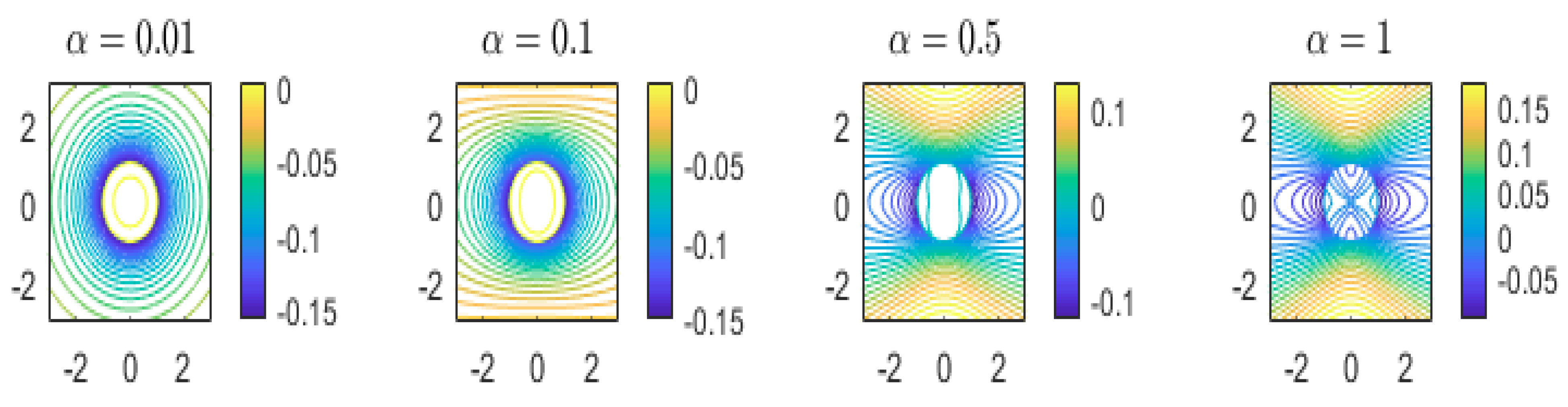
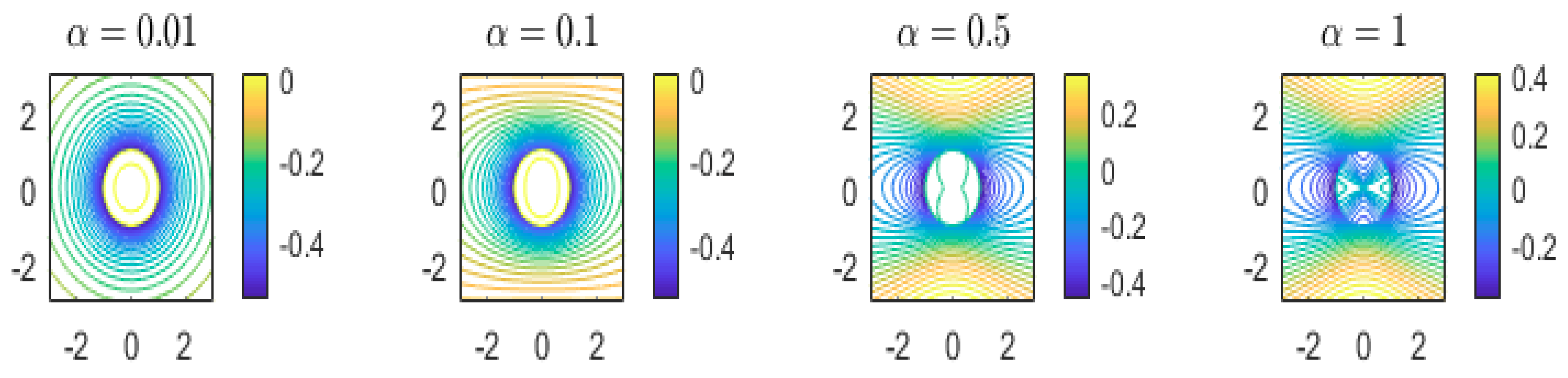
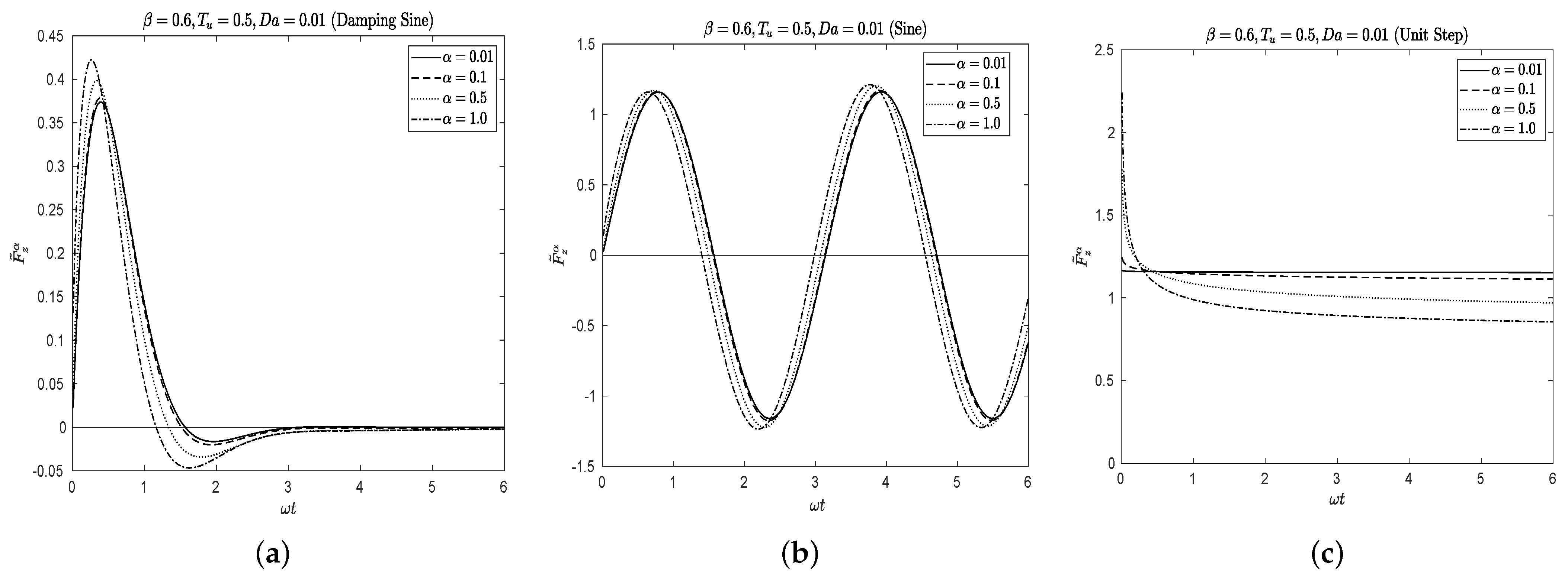
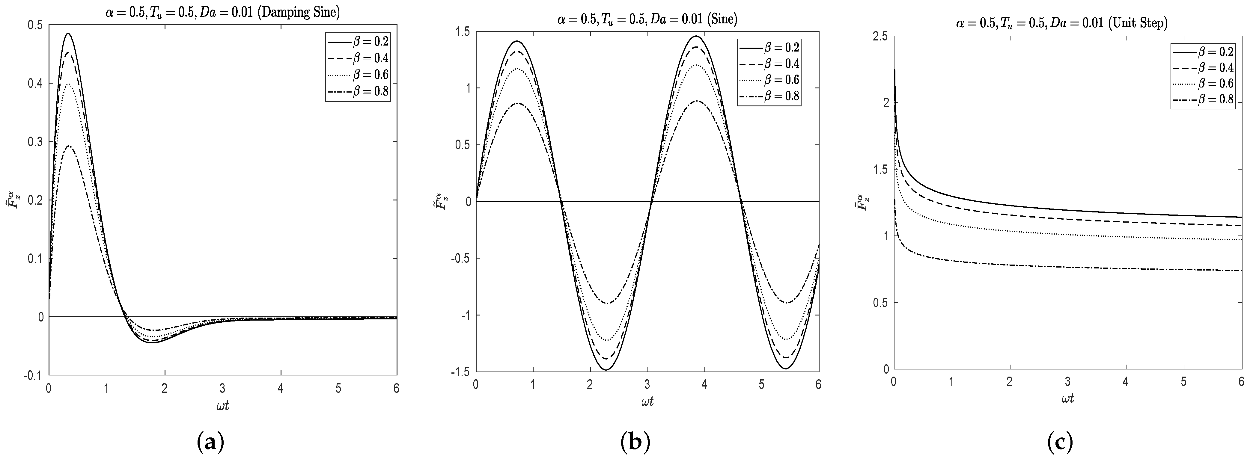
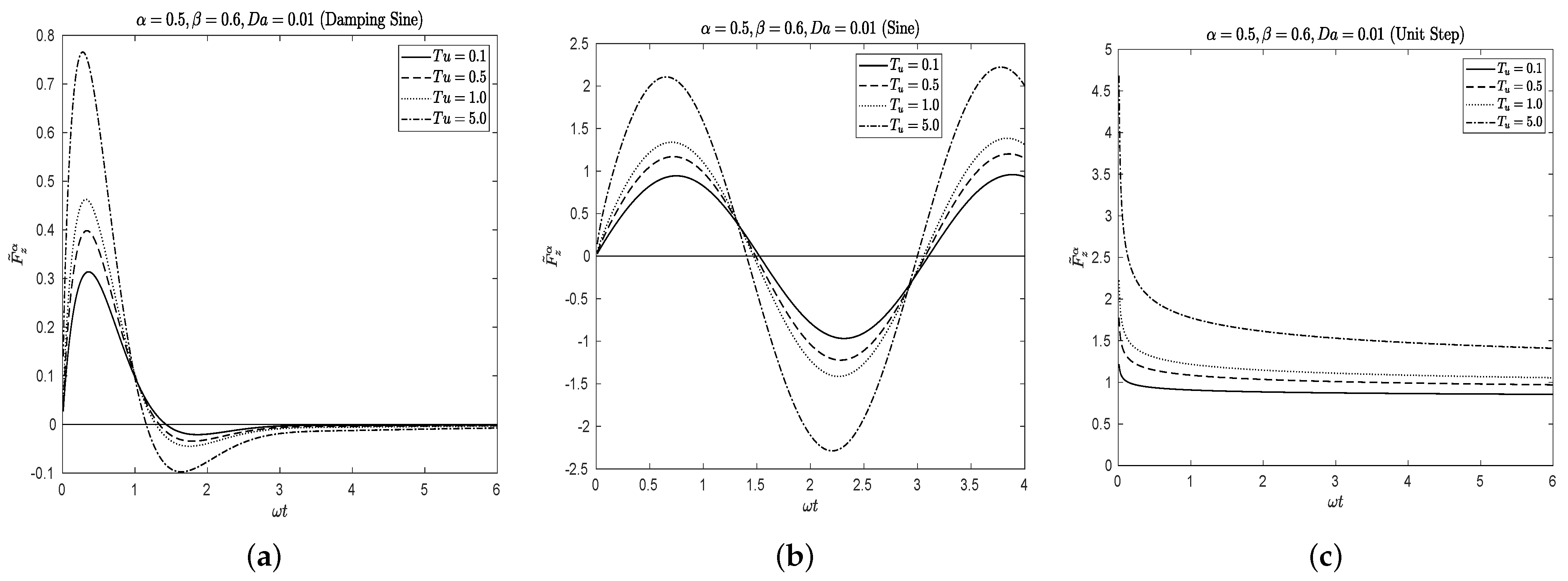
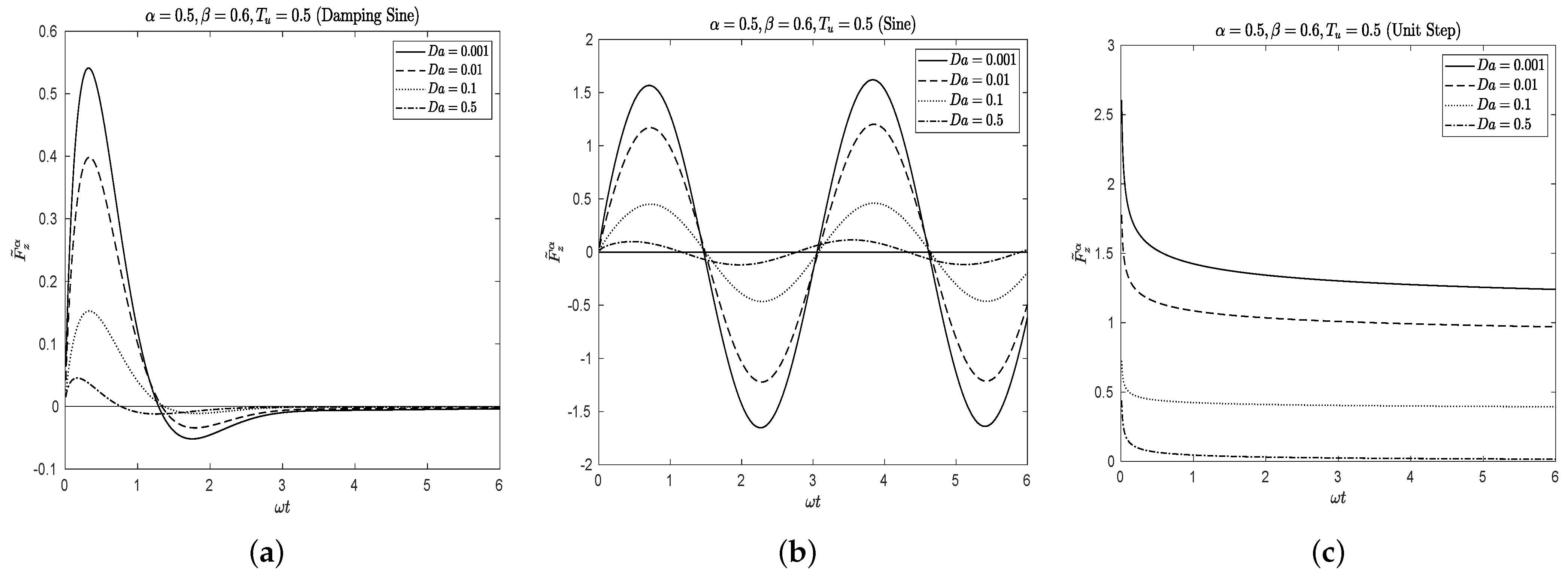
5. Numerical Results and Discussions

Here, we present some graphical representations of the streamlines for damping sine oscillation and unit step function.
Figure 1 presents streamline patterns for damping oscillations for various values of fractional parameter ( α ) at fixed T u = 0.5 , β = 0.6 , D a = 0.3 , ω = 1 and t = 0.5 . It can be seen that at smaller values of α , closed streamlines are formed inside and outside of the porous sphere (see Figure 1 at α = 0.01 and α = 0.1 ). At α = 0.1 , the streamlines in the vicinity of the porous sphere are clustered and velocity is highest around the porous sphere. This is observed because the fluid in the vicinity of the porous sphere gets accelerated due to motion of the porous sphere. The velocity decays as we move away from the porous sphere in the y-direction, because far from the porous sphere the magnitude of disturbance to the ambient fluid reduces at smaller value of α . Values of α < 0.5 do not affect the streamlines much. At α = 0.5 , the streamlines near the porous sphere get deformed in the x-direction. In addition, the velocity is maximum in the vicinity of the porous sphere and also far from porous sphere where the streamlines are clustered. At the values α 0.5 , the effect of unsteadiness is more profound as it contributes to the momentum leading to an increase in velocity far from the porous sphere. It is interesting to note that at α = 1 , closed streamlines are formed in the vicinity of the porous sphere along the x-axis. In addition, the streamlines inside the porous sphere close to the center form parabolic shape which is symmetric about the x-direction. In fact, as α grows the disturbance far from the center of the sphere grows.
Figure 2 presents streamline patterns for unit step function for various values of fractional parameter ( α ) at fixed T u = 0.5 , β = 0.6 , D a = 0.3 , t = 0.5 and ω = 1 . It may be noticed that at the smaller value of α = 0.01 , the streamlines are undeformed and clustered in the vicinity of the porous sphere leading to maximum velocity on the surface which decays far from the sphere surface. As seen in Figure 2, the smaller values of α < 0.5 do not affect the streamlines much. At α 0.5 , streamlines start getting to deform in the vicinity of the porous sphere and also inside the porous sphere. It may be noted that in case of unit step function, the magnitude of disturbance far from the center of the sphere grows as α grows, but at α = 1 , more fluid seeps through the porous sphere forming streamlines inside it as compared to the damping sine oscillation at α = 1 (see Figure 2 at α = 1 ).
Figure 3, Figure 4, Figure 5 and Figure 6 present the non-dimensional drag force, F ˜ z α , for the three cases mentioned above for different values of the fractional order parameter ( α ) , Darcy number ( D a ) , unsteadiness parameter ( T u ) and the stress jump coefficient ( β ) .
Figure 3a–c demonstrate variations of the dimensionless drag force exerted on the spherical surface for different values of the fractional derivative parameter α by fixing the other parameters such as Darcy number ( D a ) , unsteadiness parameter ( T u ) and the stress jump coefficient ( β ) . In Figure 3a–c, β , T u and D a are kept at 0.6, 0.5 and 0.01, respectively. It can be observed that the fractional order parameter ( α ) makes an effective contribution to the drag. An increase in this parameter increases the values of the drag force. The classical case of non-fractional derivative is achieved when the parameter α is assigned the value of one. It may be concluded that use of fractional order derivative in the Navier–Stokes equation leads to the reduction of drag force on spherical objects. Physically, the smaller the values of α , the more rapidly the shear decays which results in reduction of drag force. This may be due to the fractional order derivatives which examines the complete description of the memory effectively. It may also be observed that in the case of damping sine oscillations, drag force tends to zero as ω t which is large time behavior. In this case, the porous sphere does not experience any force arising due to damping effect. It is interesting to see that the particle experiences a reverse force at relatively smaller values of ω t (Figure 3a). In case of sine oscillation, the force profile exhibits oscillatory behavior and it never approaches zero (Figure 3b). Unlike the damping sine and sine oscillations, the porous sphere does not experience negative force in case of unit step function.
Figure 4a–c exhibit variations of drag force versus the time parameter for different values of stress jump coefficient ( β ) at fixed α = 0.5 , T u = 0.5 and D a = 0.01 . It can be noticed that an increase in this coefficient results in a decrease in the drag force. This may be due to the fact that increase in the stress jump coefficient ( β ) forces more fluid to seep through the porous sphere before it slips from the surface which leads to a reduction in the drag force. Figure 5a–c depict the variation of drag force versus the time parameter for different values of unsteadiness parameter ( T u ) at fixed α = 0.5 , β = 0.6 and D a = 0.01 . It may be noted that increase in unsteadiness parameter contributes to the momentum of the fluid flow which further helps the shear stress acting on the porous sphere leading to an increase in the drag force experienced by the porous sphere.
Figure 6a–c present variation of drag force versus the time parameter for different values of Darcy number ( D a ) at fixed α = 0.5 , β = 0.6 and T u = 0.5 . It can readily be seen that an increase in Darcy number ( D a ) reduces the drag force. This occurs due to the fact that increase in Darcy number increases the permeability of the porous medium which helps ease the fluid flow inside the porous particle and this leads to a decrease in the drag force. It is to be noted that the force reflects the pattern of the basic flow, for example if the basic flow is damping sine, the force exhibits damping behavior and eventually becomes zero at larger time. If the basic flow is oscillatory, the force exhibits oscillatory behavior. In case of the basic flow taken as unit step function, the force obtained is large in magnitude at ω t = 0 and the magnitude decreases as ω t grows. It can be concluded that the use of fractional order derivatives exhibits the history (‘memory’) of the basic flow in the obtained physical quantities of interest.

6. Conclusions

This paper presents a semi analytical solution for the problem of unsteady translational motion of a porous sphere in an incompressible viscous fluid. The fluid flow exterior and interior of the porous sphere is governed by the modified Navier–Stokes equation with fractional time derivative and the modified Brinkman equation with fractional time derivative. The Laplace transform technique is used and the inversion is obtained with the aid of numerical inversion formula of Laplace transform. Streamline patterns for damping sine and unit step function are presented. It was observed that increase in the fractional parameter α increases the disturbance far from the center of the porous sphere in both the cases. However, it was noticed that at smaller values of α , the streamlines do not deform outside and inside the porous sphere. It may also be noted that in case of unit step function, at α = 1 , more fluid seeps through the porous sphere resulting in formation of clustered streamlines leading to increase in velocity inside the porous sphere compared to the case of damping sine oscillation. The drag force formula is obtained analytically in Laplace domain and is inverted numerically. Variation of the drag force with various parameters such as fractional parameter ( α ) , stress jump coefficient ( β ) , unsteadiness parameter ( T u ) and Darcy number ( D a ) is discussed graphically. It is concluded from the numerical results that the fractional order parameter, α , contributes considerably on the drag force. It is observed that the values of the drag force increase with increase of this parameter. In addition, it is observed that drag force decreases with stress jump coefficient and Darcy number whereas it increases with unsteadiness parameter.

Author Contributions

Conceptualization, J.P.; methodology, J.P.; software, J.P. and C.S.; validation, J.P. and C.S.; formal analysis, J.P.; investigation, J.P.; writing—original draft preparation, J.P. and C.S.; writing—review and editing, J.P.; supervision, J.P. All authors have read and agreed to the published version of the manuscript.

Funding

This research was funded by Science and Engineering Research Board (SERB) sanction order no. MTR/2017/000446.

Acknowledgments

One of the authors (J.P.) acknowledges the support by Science and Engineering Research Board (SERB) sanction order no. MTR/2017/000446.

Conflicts of Interest

The authors declare that they have no conflict of interest.

References

  1. Caputo, M. Diffusion with space memory modelled with distributed order space fractional differential equations. Ann. Geophys. 2003, 46, 223–234. [Google Scholar]
  2. Hilfer, R. Applications of Fractional Calculus in Physics; World Scientific Publishing: Singapore, 2000. [Google Scholar]
  3. Kumar, S. A new analytical modelling for fractional telegraph equation via Laplace transform. Appl. Math. Model. 2014, 38, 3154–3163. [Google Scholar] [CrossRef]
  4. Kumar, S.; Kumar, D.; Abbasbandy, S.; Rashidi, M.M. Analytical solution of fractional Navier–Stokes equation by using modified Laplace decomposition method. Ain Shams Eng. J. 2014, 5, 569–574. [Google Scholar] [CrossRef] [Green Version]
  5. Zhou, Y.; Peng, L. On the time fractional Navier-Stokes equations. Comput. Math. Appl. 2017, 73, 874–891. [Google Scholar] [CrossRef]
  6. Wang, K.; Liu, S. Analytical study of time-fractional Navier-Stokes equation by using transform methods. Adv. Differ. Equ. 2016, 2016, 61. [Google Scholar] [CrossRef] [Green Version]
  7. Stokes, G.G. On the effect of the internal friction of fluids on the motion of pendulums. Trans. Camb. Philos. Soc. 1851, 9, 8–106. [Google Scholar]
  8. Basset, A.B. On the motion of a sphere in a viscous liquid. Philos. Trans. R. Soc. Lond. A 1888, 179, 43–63. [Google Scholar]
  9. Feng, J.; Joseph, D.D. The unsteady motion of solid bodies in creeping flows. J. Fluid Mech. 1995, 303, 83–102. [Google Scholar] [CrossRef] [Green Version]
  10. Michaelides, E.E.; Feng, J.-G. The Equation of Motion of a Small Viscous Sphere in an Unsteady Flow with Interface Slip. Int. J. Multiph. Flow 1995, 21, 315–321. [Google Scholar] [CrossRef]
  11. Choudhuri, D.; Padmavati, B.S. A study of an arbitrary unsteady Stokes flow in and around a liquid sphere. Appl. Math. Comput. 2014, 243, 644–656. [Google Scholar] [CrossRef]
  12. Bogoyavlenskij, O.I. Exact unsteady solutions to the Navier-Stokes and viscous MHD equations. Phys. Lett. A 2013, 307, 281–286. [Google Scholar] [CrossRef]
  13. Ardekani, A.M.; Rangel, R.H. Unsteady motion of two solid spheres in Stokes flow. Phys. Fluids 2006, 18, 103306. [Google Scholar] [CrossRef] [Green Version]
  14. Ashmawy, E.A. Unsteady Rotational Motion of a Slip Spherical Particle in a Viscous Fluid. ISRN Math. Phys. 2012, 2012, 513717. [Google Scholar] [CrossRef] [Green Version]
  15. Ashmawy, E.A. Rotary oscillation of a composite sphere in a concentric spherical cavity using slip and stress jump conditions. Eur. Phys. J. Plus 2015, 130, 163. [Google Scholar] [CrossRef]
  16. Jaber, K.K.; Ahmad, R.S. Analytical solution of the time fractional Navier-Stokes equation. Ain Shams Eng. J. 2018, 9, 1917–1927. [Google Scholar] [CrossRef]
  17. Ashmawy, E.A. Unsteady translational motion of a slip sphere in a viscous fluid using the fractional Navier-Stokes equation. Eur. Phys. J. Plus 2017, 132, 142. [Google Scholar] [CrossRef]
  18. Xu, H.; Jiang, X.; Yu, B. Numerical analysis of the space fractional Navier–Stokes equations. Appl. Math. Lett. 2017, 69, 94–100. [Google Scholar] [CrossRef]
  19. Kashif, A.A.; Ilyas, K. MHD flow of fractional Newtonian fluid embedded in a porous medium via Atangana-Baleanu fractional derivatives. Discret. Contin. Dyn. Syst. 2020, 13, 377–387. [Google Scholar]
  20. Zhou, Y.; Peng, L.; Ahmad, B.; Alsaedi, A. Energy methods for fractional Navier–Stokes equations. Chaos Solitons Fractals 2017, 102, 78–85. [Google Scholar] [CrossRef]
  21. Kang, J.; Zhou, F.; Xia, T.; Ye, G. Numerical modeling and experimental validation of anomalous time and space subdiffusion for gas transport in porous coal matrix. Int. J. Heat Mass Trans. 2016, 100, 747–757. [Google Scholar] [CrossRef]
  22. Muzaffar, H.L.; Kashif, A.A.; Asif, A.S. Helical flows of fractional viscoelastic fluid in a circular pipe. Int. J. Adv. Appl. Sci. 2017, 4, 97–105. [Google Scholar]
  23. Zafar, A.A.; Fetecau, C. Flow over an infinite plate of a viscous fluid with non-integer order derivative without singular kernel. Alex. Eng. J. 2016, 5, 2789–2796. [Google Scholar] [CrossRef] [Green Version]
  24. Nadeem, A.S.; Ali, F.; Khan, I.; Saqib, M. A modern approach of Caputo-Fabrizio timefractional derivative to MHD free convection flow of generalized second grade fluid in a porous medium. Neural Comput. Appl. 2018, 30, 1865–1875. [Google Scholar]
  25. Atangana, A.; Baleanu, D. Caputo-Fabrizio derivative applied to groundwater flow within confined aquifer. J. Eng. Mech. 2016, 142, D4016005. [Google Scholar] [CrossRef]
  26. Ochoa-Tapia, J.A.; Whitaker, S. Momentum transfer at the boundary between a porous medium and a homogeneous fluid—I. theoretical development. Int. J. Heat Mass Transf. 1995, 38, 2635–2646. [Google Scholar] [CrossRef]
  27. Ochoa-Tapia, J.A.; Whitaker, S. Momentum transfer at the boundary between a porous medium and a homogeneous fluid—II. comparison with experiment. Int. J. Heat Mass Transf. 1995, 38, 2647–2655. [Google Scholar] [CrossRef]
  28. Haq, S.U.; Khan, M.A.; Shah, N.A. Analysis of Magnetohydrodynamic Flow of a Fractional Viscous FluidThrough a Porous Medium. Chin. J. Phy. 2018, 56, 261–269. [Google Scholar] [CrossRef]
  29. Khan, Z.A.; Haq, S.U.; Khan, T.S.; Khan, I.; Nisar, K.S. Fractional Brinkman type fluid in channel under the effect of MHD with Caputo-Fabrizio fractional derivative. Alex. Eng. J. 2020, 59, 2901–2910. [Google Scholar] [CrossRef]
  30. Sekhar, G.R.; Amaranath, T. Stokes flow past a porous sphere with an impermeable core. Mech. Res. Commun. 1996, 23, 449–460. [Google Scholar] [CrossRef]
  31. Nield, D.A. Modelling fluid flow and heat transfer in a saturated porous medium. Adv. Decis. Sci. 2000, 4, 165–173. [Google Scholar] [CrossRef]
  32. Prakash, J.; Sekhar, G.R. Slow motion of a porous spherical particle with a rigid core in a spherical fluid cavity. Meccanica 2017, 52, 91–105. [Google Scholar] [CrossRef]
  33. Stehfest, H. Algorithm 368: Numerical inversion of Laplace transforms. Commun. ACM 1970, 13, 47–54. [Google Scholar] [CrossRef]
  34. Talbot, A. The accurate numerical inversion of Laplace transforms. IMA J. Appl. Math. 1979, 23, 97–120. [Google Scholar] [CrossRef]
  35. Abate, J.; Whitt, W. A Unified Framework for Numerically Inverting Laplace Transforms. INFORMS J. Comput. 2006, 18, 408–421. [Google Scholar] [CrossRef]
  36. Doetsch, G. Introduction to the Theory and Application of the Laplace Transformation; Springer: New York, NY, USA, 1974. [Google Scholar]
  37. Abate, J.; Whitt, W. The Fourier-series method for inverting transforms of probability distributions. Queueing Syst. 1992, 10, 5–88. [Google Scholar] [CrossRef]
  38. Abate, J.; Choudhury, G.L.; Whitt, W. An introduction to numerical inversion and its application to probability models. In Computational Probability; Grassman, W., Ed.; Kluwer: Boston, MA, USA, 1999; pp. 257–323. [Google Scholar]
  39. Abate, J.; Valko, P.P. Multi-precision Laplace inversion. Int. J. Numer. Methods Eng. 2004, 60, 979–993. [Google Scholar] [CrossRef]
  40. Hosono, T. Numerical inversion of Laplace transform and some applications to wave optics. Radio Sci. 1981, 16, 1015–1019. [Google Scholar] [CrossRef]
  41. Hosono, T. Fast Inversion of Laplace Transform by BASIC; Kyoritsu Publishers: Tokyo, Japan, 1984. (In Japanese) [Google Scholar]
Figure 1. Streamlines at different α and ω = 1 for case 1 (damping oscillation).
Colloids 05 00024 g001
Figure 2. Streamlines at different α and ω = 1 for case 3 (unit step function).
Colloids 05 00024 g002
Figure 3. Variation of drag force for all three cases: (a) damping sine oscillation, (b) sine oscillation, (c) unit step function.
Colloids 05 00024 g003
Figure 4. Variation of drag force at different β for all three cases: (a) damping sine oscillation, (b) sine oscillation, (c) Unit step function.
Colloids 05 00024 g004
Figure 5. Variation of drag force at different T u for all three cases: (a) damping sine oscillation, (b) sine oscillation, (c) Unit step function.
Colloids 05 00024 g005
Figure 6. Variation of drag force at different D a for all three cases: (a) damping sine oscillation, (b) sine oscillation, (c) Unit step function.
Colloids 05 00024 g006
Publisher’s Note: MDPI stays neutral with regard to jurisdictional claims in published maps and institutional affiliations.

