Article

A Methodology for Generating Systems Architectural Glimpse Statements Using the 5W1H Maxim

1
School of Electrical and Computer Engineering, National Technical University of Athens, 15773 Athens, Greece
2
Research Institute of Environment and Information Sciences, Yokohama National University, Kanagawa, Yokohama 240-8501, Japan
3
Faculty of Environment and Information Studies, Keio University, Endo, Kanagawa, Fujisawa 252-0882, Japan
4
R&D Delivery Department, Worldline Iberia SA, 08020 Barcelona, Spain
5
Graduate School of Media and Governance, Keio University, Endo, Kanagawa, Fujisawa 252-0882, Japan
*
Author to whom correspondence should be addressed.
Submission received: 10 September 2021 / Revised: 30 September 2021 / Accepted: 9 October 2021 / Published: 15 October 2021
(This article belongs to the Special Issue Edge and Cloud Computing in IoT)

Abstract

:
Attempts to facilitate and streamline systems architecting have resulted in a great number of reusable principles, practices, mechanisms, frameworks, and tools. Such a practice is the use of architectural viewpoints and views. However, as systems change, these practices should also evolve. The increasing scale and complexity of systems resulting from an ever-growing pool of human needs and breakthroughs may lead, in some cases, to an increased gap between the abstraction activities attempting to capture the whole of a system, and the instantiation activities that produce concrete and detailed descriptions of a system’s architecture. To address this issue, this article introduces a new notion, that of architectural glimpse statements, fundamental questions acting as the building blocks for architectural views and products. This notion can help architects ask the right questions in the right manner to create fundamental statements, the elaboration on which can lead directly to concrete architectural products. Working on top of standardized and common approaches, the article introduces a language for the creation of architectural glimpse statements using the 5W1H maxim. Based on this language, a tool and guidelines are also provided to facilitate the usage of glimpses. Finally, the overall methodology is demonstrated in two case studies.

1. Introduction and Problem Statement

1.1. Systems Architecture and Architecting

Under the context of systems engineering, every system (individual applications, systems in the traditional sense, subsystems, systems of systems, product lines, product families, whole enterprises, and other aggregations of interest) can be considered to have an architecture [1], a conceptual construct that represents the fundamental organization of a system embodied in its components, their relationships to each other and to the environment, and the principles guiding its design and evolution [2].
Architecting in general refers to all the activities related to the definition, certification, maintenance, improvement, and documentation of proper implementations (instantiations) of architectures. The definition of architectures can be implemented through architectural analysis (understanding the environment in which a proposed system will operate and determining the requirements for the system) and architectural synthesis (transforming needs and requirements in a specific design). The certification of an implemented architecture is supported by architecture evaluation (determining how well the current design or a portion of it satisfies the requirements derived during analysis). The maintenance and improvement of an architecture refers to the architecture evolution (maintaining and adapting an existing architecture to meet changes in requirements and environment) [3]. Finally, regarding the documentation activity, an architecture can be recorded by an architectural description (AD) [1]. A distinction should be made between the architecture of a system (conceptual construct) and particular descriptions of that architecture (concrete products or artifacts). For the same architecture, several ADs can be produced.
The architects are the ones responsible for capturing the systems architecture. Architects have to identify the concerns of stakeholders, the mission behind a system to be developed, the environment characteristics related to the system, etc. and, using a combination of engineering and intuition (or art), create a series of abstract and specific models, mostly in a top-down manner [4]. In other words, the main contribution of the architect is the conceptualization and design of a unique structure to meet specific needs. As such, the architect’s role in development projects (and not only) is really important, as the ADs they produce during the concept and design phases set the baseline for steps to be followed during e.g., the development, implementation, and deployment phases. The ADs can facilitate communication between the several system stakeholders, provide the basis for analysis of systems’ behavior before actually building the systems, offer the opportunity of re-using already available elements, etc.
In an ever-changing world, new needs and breakthroughs constantly appear that increase both the scale and the complexity of systems. New organizational and social structures, an expanding spectrum of operations and applications representing all human activities, and rapid changes in technology act as a driving force for the creation (and, inevitably, the architecting) of new systems. A characteristic example of such a change is the appearance of the vision of the creation of the Internet of Things (IoT). The IoT leads to networks connecting billions of real-time interacting and communicating things, creating huge ICT systems that expand in a great variety of administrative domains. Another more recent example is the appearance of the vision of connecting the IoT to Earth Observation (EO) systems and the geospatially enabled web as investigated in [5].
The increasing scale and complexity of developed and managed systems makes architecting more and more necessary, but also, more and more challenging. This pertains to the fact that architecture is an intellectually graspable abstraction of a complex system which, even though Computer-Aided Software Engineering (CASE) tools are available, is primarily produced directly by the human intellect and recorded in ADs.

1.2. Motivation, Contributions, and Paper Structure

Given the scale and complexity of systems and the interdisciplinary nature of systems engineering, in an attempt to facilitate and streamline architecting, a great number of reusable principles, practices, mechanisms, and tools of identifying, representing, and materializing architectures have been produced, while specific architecture processes have been identified and standardized [6]. Such a practice is the use of architectural viewpoints and views [1]. However, as is discussed in Section 2, such solutions still have some limitations, whereas, in many cases, it is necessary for architects to create composite solutions of their own, due to the particularities of the systems they have to design or analyze [7]. Most importantly though, these solutions tend to follow a primarily top-down approach, without any further instructions through which architects can move from an initially abstract view of their system to more concrete and specific results.
To address this issue, this article introduces a new notion, that of Systems Architectural Glimpses. The resulting architectural glimpse statements are fundamental questions acting as the building blocks for architectural views and products. As such, the first contribution of this article is the introduction of the very concept of glimpses as a means to following a bottom-up approach for producing architectural products. The second contribution is the definition of a specific language through which glimpse statements can be constructed methodically. The third contribution is the identification and classification of several entities of interest related to systems engineering based on international standards. Finally, the fourth contribution is a pen-and-paper “generator” of glimpse statements and a set of guidelines through which the extraction of glimpses can be realized.
The aforementioned contributions are addressed in this article in seven sections. Section 2 presents the related work on solutions for architecture description extraction, focusing mainly on architectural views. The section provides all the background information needed to identify the necessity of architectural glimpses (complex systems, abstract approaches). Section 3 introduces the concept of architectural glimpses and architectural glimpse statements and identifies the relations between them and other related concepts such as architectural views. Section 4 presents a recommended language through which it can be ensured that glimpse statements can be well-defined. To that end, the section suggests the usage of the 5W1H maxim as an appropriate practice for the construction of glimpse statements, and elaborates further on matters related to the corresponding needed linguistics, such as the required context identification, vocabulary population, grammar and syntax formation, and semantics construction. Section 5 presents a tool that codifies all the language concepts and rules of the suggested glimpse statements language and produces useful glimpse statements following specific guidelines. Section 6 provides examples of glimpse statements and shows through two case studies how glimpses can be used (a) to construct new architectures, and (b) to decompose already identified architectural products (demonstrating compatibility with other architecting practices). Finally, Section 7 discusses issues related to the usage of the suggested methodology and identifies next steps for future work, while Section 8 concludes the paper.

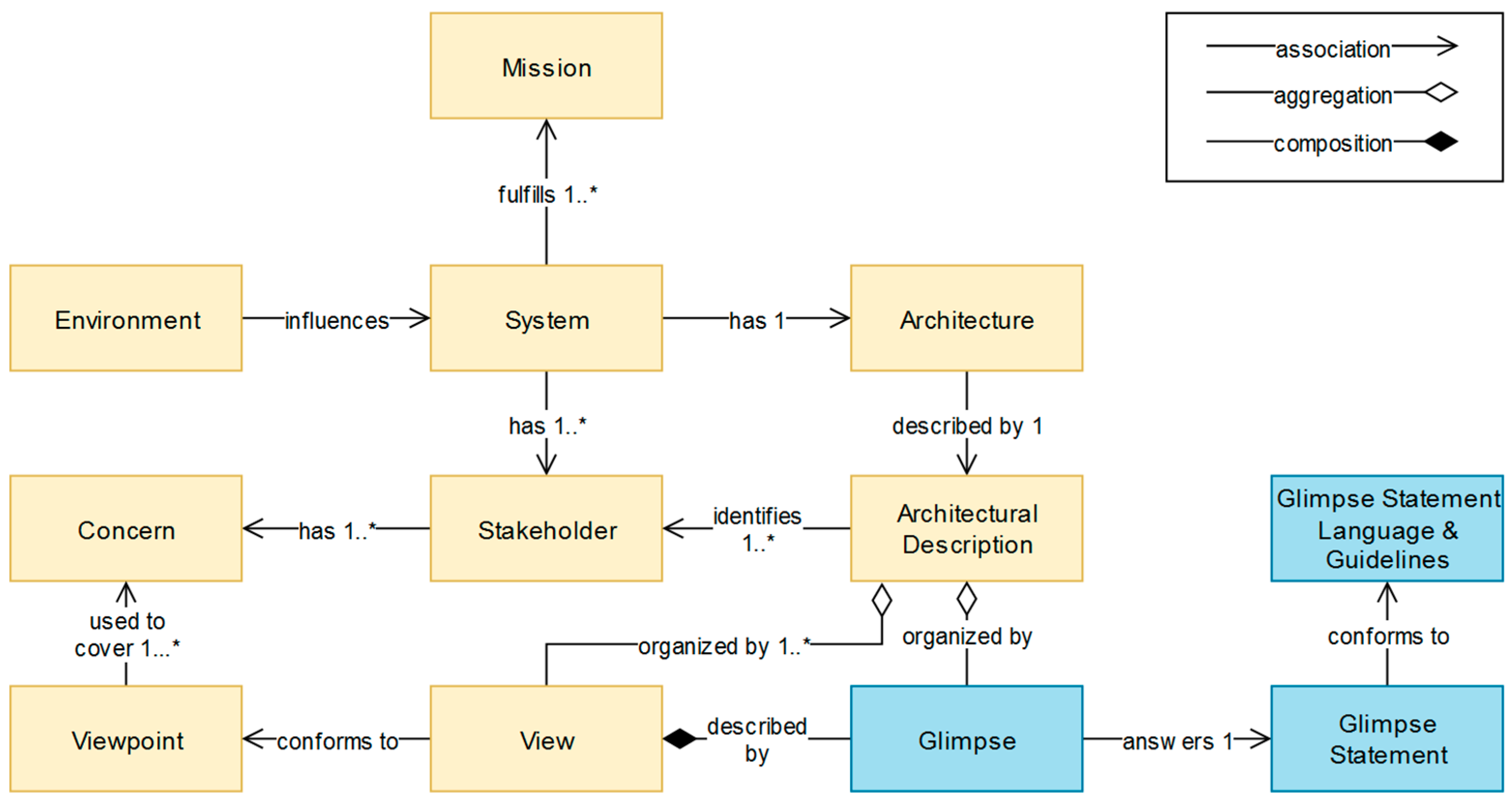
2. Related Work: Architectural Views and Other Approaches

As stated above, a great number of reusable principles, practices, mechanisms, and tools of identifying, representing, and materializing architectures have been produced. By studying the terms and the corresponding literature cited in [2], the following reusable notions of interest are identified:
  • Architectural design methodology: “Systematic approach to creating an architectural design consisting of the ordered application of a specific collection of tools, techniques, and guidelines”.
  • Architectural technique: “Systematic procedure to perform an activity to produce an architectural product, that may employ one or more tools”. An example is the Structured Analysis and Design Technique (SADT) [8] upon which IDEF0 [9] is based.
  • Architectural style: “Definition of a family of systems in terms of a pattern of structural organization”. Depending on the styles used, an architecture may be layered, component-based, (micro-) service-oriented, function-oriented, object-oriented, data-centric, event-driven, rule-based, etc.
  • Architecture framework (AF): A reusable architectural design (models and/or code) that can be refined (specialized) and extended to provide some portion of the overall functionality of many applications. A framework is usually implemented in terms of one or more viewpoints or architecture description languages.”
  • Architectural model: “A semantically closed abstraction of a system or a complete description of a system from a particular perspective.”
  • Architectural views: “A representation of a whole system from the perspective of a related set of concerns.”
  • Architecture description language (ADL): “Any means of expression used to describe a software architecture.”
Most architects must operate within the confines of a prescribed architecture framework or architecture description language as dictated by their organization or client [7]. Current architectures and AFs (like the ones presented in [10,11]) and ADLs (such as the ones introduced in [12,13]) are defined with varying degrees of rigour and offer varying levels of tool support. Furthermore, these resources are mostly closed: their developers expect that each framework or ADL is all that an architect will ever need. For example, frameworks may be tailored downward, some suggested viewpoints or model kinds may be omitted in use, etc., but rarely there are means for extension provided.
Compared to AFs and ADLs, architectural viewpoints in general give more flexibility to architects. The use of architectural views for architectural descriptions is a generally accepted trend and a common practice followed by various initiatives, also included as part of the ISO/IEC/IEEE international standards series [14]. Each view addresses a set of system concerns, following the conventions of its viewpoint, where a viewpoint is a specification that describes the notations, modeling, and analysis techniques to use in a view that expresses the architecture in question from the perspective of a given set of stakeholders and their concerns. A viewpoint can be considered as a template from which to develop individual views by establishing the purposes and audience for a view and the techniques for its creation and analysis. Through the use of viewpoints and views, simplified models can be formed including only those entities of interest (see Section 4.2) related to the corresponding concerns. For example, a data viewpoint focuses on the data as they are realized and manipulated within the system. Given the interdisciplinary nature of systems engineering, architectural viewpoints and views make it easier to organize entities of interest of complex systems around different domains of expertise that can then be naturally assigned to the corresponding experts. In other words, views make it possible to examine a “slice” or a portion of a particular interest area in a system or the system’s environment, while the complete representation of the corresponding architecture requires different views.
In literature, several types of system view models can be found, which suggest different types of views. Indicatively, in [15], the “4 + 1 View Model of architecture” introduced by P.Kruchten in 1995 identifies a logical view (the object model of the design), a process view (concurrency and synchronization aspects of the design), a physical view (mappings of S/W to H/W), and a development view (static organization of the software in its development). The description of architecture can be organized around these four views, and then illustrated by a few selected scenarios which become a fifth view. In [16], the Reference Model of Open Distributed Processing (RM-ODP), a joint effort by the international standards bodies ISO and ITU-T to develop a coordinating framework for the standardization of open distributed processing, defines the following five viewpoints: enterprise viewpoint (purpose, scope, and policies), information viewpoint (semantics of information and information processing), computational viewpoint (functional decomposition), engineering viewpoint (infrastructure required to support distribution), and technology viewpoint (choices of technology for implementation). The C4ISR Architecture Framework document [17] issued by the Department of Defense specifies three views of information architecture: operational view, systems view, technical, and standards view (a fourth view can be considered an “Overarching All View”). The authors in [18] are focusing on providing an IoT Architecture Reference model, and identify a domain viewpoint, an information viewpoint, a functional viewpoint, and a communication viewpoint. In [19], the Reference Architecture for Modeling Space Systems (RAMSS) extends the RM-ODP and identifies more than 20 different views based on viewpoint specifications, expressed in terms of “objects”. One of the latest additions is [20], which introduces an operational view as a “forgotten architectural view”.
Different initiatives that introduce views and viewpoints such as the above follow a top-down approach to define architectures and they often include guidelines on how to instantiate views. For example, in [17], the authors provide an extensive list of architecture products (deliverables) that are mapped to specific views. However, sometimes, viewpoints may be deemed to be too conceptual, and the guidelines to extract final results and products from them may be insufficient, especially when very complex systems are considered.

3. Architectural Glimpses

In order to generate views, an architect has to extract or represent at some point of analysis and/or design all the necessary information for all entities of interest within the system or the system’s environment. As architects attempt to get clearer and clearer views of the several elements of the system, they will move from high-level questions (e.g., “What is the functional view of the system?”) to concrete ones. For example, the requirements view identified in [19] can be considered to face the challenge of describing the requirements, goals, and objectives that drive the system and states what the system must be able to do. There is an unlimited number of concrete questions that can be stated in order to break down this challenge into more specific sub-challenges. On the same example, questions that could be extracted are: “What system functional requirements have to be covered, and what are the constraints for covering them?”, “What are the goals to be fulfilled, how can or must they be fulfilled, at which date or with what sequence do they have to be fulfilled exactly?”, “What are the user requirements that have been extracted, with what means were they extracted, from what stakeholders were they extracted, and by which stakeholder were they extracted?”, “What are the technical requirements that are already covered, through which functional component are they already covered, and by whom are they covered?”, etc. The first question could be answered through a simple populated table including columns such as “requirement code”, “requirement description”, “constraints on requirement fulfillment”; the second question could be answered through a table with similar columns and an accompanying sequence diagram, etc. The more concrete and well-defined the questions are, the easier it is to identify the content of their answers and the means to produce them. Βy asking the right questions in the right manner, it is possible to create fundamental statements, the elaboration on which can lead directly to concrete architectural (sub-)products. The answers to these fundamental statements can be seen as the elemental, building blocks of views. Based on the above, we introduce the notion of architectural glimpses.
Definition 1:
An architectural glimpse is the representation of a detailed answer to a very concrete (not abstract) and, in some cases, complex (containing more than one interrogatives) question related to a specific action performed on a particular system entity of interest, so as to facilitate architecting.
As the name suggests, architectural glimpses (referred to as “glimpses” in the remainder of the article) provide a partial view of a system. In other words, glimpses, on a conceptual level, can be understood as the elemental parts of views. The concrete questions on which these glimpses are based are referred to as glimpse statements. Glimpse statements are the lowest-level questions that can be asked in order to analyze or design a system and define the context of glimpses which are represented through documentation artifacts such as tables, textual descriptions, diagrams, etc. If views can be understood as elements of top-down approaches, glimpses can be understood as elements of bottom-up approaches.
Given the huge number of entities of interest and of the actions that can be performed on the said entities, it can be realized that there is a practically infinite number of glimpse statements that can be produced (this is made more clear in Section 5). For glimpse statements to be useful during architecting, they should not be ambiguous, and they should be accompanied by a set of rules through which their creation and selection can be methodized.
To that end, on one hand we need a concrete definition of concepts and rules (a language) for the specification of glimpse statements, and on another hand a series of steps through which an architect can identify which are the possible glimpse statements that they can use, and which glimpse statements are the ones necessary to be used (guidelines).
Figure 1 provides an informative summary of the relationships between key concepts introduced in Section 1 and Section 2. For this representation, the Unified Modeling Language (UML) [21] is used. Boxes represent classes of concepts, whereas the different lines connecting them represent different types of relations (association, aggregation, composition). Association relations are not one-way ones in the strict sense, but are presented as such to simplify the overall view. The figure does not include all of the possible relationships between these concepts, but focuses on the main ones of interest for this paper. The boxes in yellow represent concepts as described in [1,2], whereas the boxes in light blue represent concepts unique in this paper. The “1..*” symbol means “one or more” (for example, a System has one or more Stakeholders).

4. Glimpse Statements Language (GSL)

4.1. Context: Asking the Right Questions (5W1H Maxim)

The problem of creating glimpse statements is the same as stating questions related to a specific action performed on a particular system entity of interest. Questions function as requests for information and the context of the questions per se (how they are interpreted) is defined partially by the interrogative words used to express them. In order to acquire rich answers, the usage of a combination of interrogative words is necessary. The question “What components are deployed on what layer (Where) with what priority/sequence (When)” is much richer and more useful than the plain question “What components are deployed?”. Of course, there is a tradeoff between expressiveness and complexity that has to be taken under consideration. A very complex question may be too hard to answer and should probably be broken down into simpler questions.
A common, popular, and straightforward way to bring the main interrogatives of the English natural language together is by using the “five Ws and one H” maxim (5W1H maxim): “What”, “Who”, “Where”, “When”, “Why”, and “How”. Beyond being a (mostly informal and non-standardized) rule of conduct used in journalism or problem-solving activities, the maxim has also been used to propose frameworks that aid computer-assisted context management and reasoning, as demonstrated in, for example, [22] which introduces an ontological context-aware model based on this maxim.
Considering all of the above, in order to set the basis for identifying the context of glimpse statements, in this specific GSL, we choose to use the 5W1H maxim. It should be noted that in no way this maxim is considered the only one that can be used to build a GSL or even the optimal one. However, from the experience of the authors, this approach is considered to achieve a good balance between expressiveness (possible combinations) and complexity (ease of use).
What remains at this point is to identify the context hidden behind each interrogative used. Under the context of this article, the five Ws and one H are used to represent the following:
  • What: It identifies the main entity of interest that can act as a subject in a glimpse statement (see Section 4.2 and Section 4.3 for further elaboration).
  • Who: It addresses concepts such as “role”, “actor”, “stakeholder”, or “beneficiary”.
  • Where: It addresses concepts related to physical or conceptual “location”.
  • When: It addresses concepts related to “time” (duration, sequence, etc.).
  • Why: It addresses concepts related to “purpose”, “goals”, etc.
  • How: It addresses concepts related to “processes”, implementation of “activities”, ways of conduct, etc.

4.2. Vocabulary: Entities of Interest and Verbs

The provided definition in Section 3 links the concept of glimpses with that of entities of interest. As “entities of interest” (hereon “entities”), we identify fundamental things of relevance to the architecture about which information should be kept. Entities can be physical (discrete, identifiable parts of the physical environment, e.g., humans, animals, plants, vehicles, store or logistics chain items, electronic appliances, or open environments, etc.), digital (any computational or data element of an ITC-based system, e.g., a program, data store, etc.), virtual (computational or data elements representing physical entities), or conceptual (mental concepts, e.g., a requirement, a goal, time, process, etc.). Each entity belongs to at least one class of entities, i.e., an Entity Type, and each entity type represents at least one entity. For example, the term “computer” corresponds to an entity type, whereas the personal computer of the second author of this article is a specific entity of entity type “computer”, “equipment”, “machine”, etc. The same definition also mentions a “specific action performed on a particular system entity of interest”. This action is a necessary element in our approach, as, together with the 5W1H maxim, it gives context to glimpse statements. As it will be seen in Section 4.3, the action is the glue between all the phrases in our grammar. Asking “What data (What) are extracted (Action), by which end-users (Who)” is a completely different statement from “What data (What) are secured (Action), by which end-users (Who)”. Nouns and nominal phrases (entity types), and verbs (actions), together with the interrogatives mentioned in the previous section, and some more elements to be presented in Section 4.4 constitute the vocabulary used in this GSL. The more entity types and verbs are identified, the more expressive the GSL becomes and the more glimpse statements can be created.
There are two processes that took place in order to define the vocabulary of this GSL. The first one is the extraction of fundamental entity types and actions. The second one is the formation of simple rules through which more entity types and actions can be produced by using fundamental entities, verbs, or concepts.
The fundamental entity types and actions were extracted through a very extensive and meticulous search in the literature. As a first step, specific characteristics by which the considered literature should abide were identified. The considered sources should:
  • Criterion 1: aggregate terms from several systems engineering domains, in order to provide a holistic view of all the corresponding related concepts and avoid focusing on terms that are too domain- or application-specific.
  • Criterion 2: use as sources standards, in order to support standardization activities and ensure “interoperability” of the produced vocabulary with other initiatives.
  • Criterion 3: have an extensive number of terms and, ideally, the meanings of the terms, in order to make it possible to work on a big pool of terms.
  • Criterion 4: have a public dissemination level, in order to make it possible for the authors of this article to easily access the said sources on the one hand, and, on other hand, to freely republish content from the sources.
The ISO/IEC/IEEE International Standard-Systems and software engineering–Vocabulary [2] fulfills all of the above criteria, and as such, it was selected as the primary source for the extraction of fundamental entity types and verbs. This International Standard was prepared to collect and standardize terminology currently in use in the field of systems and software engineering, and standard definitions for these terms. The source is not only a standard on its own, but it also uses around 100 other standards sources as references. The definitions in this International Standard are drawn from normative standards and informative guidance documents, including ISO Technical Reports (TR). The standard was prepared with the contributions of the International Organization for Standardization (ISO), the International Electrotechnical Commission (IEC), the Institute of Electrical and Electronics Engineers (IEEE), and Project Management Institute (PMI). The version of the standard that was studied [23] included 3349 terms and definitions in total. The primary tool for maintaining this vocabulary is a database publicly accessible at [24]. The copyright notice provided with the database permits users to copy definitions from the database as long as the source is cited.
The second step for the extraction of fundamental entity types and verbs was the filtering of the terms included in the chosen source. From the 3349 terms that were studied, 292 terms were selected as candidate ones from which fundamental entity types and verbs can be extracted. These terms can be found in Table S1. All terms that appear in this article in italics can be found in this table with their definitions. This filtering took place in an intuitive way, but it follows a few loose rules. For example, terms that did not pass through this filtering were mostly: one-word adjective terms (e.g., “acceptable”), acronyms, terms with more than three words (e.g., “attribute for quality measure”), terms that referred to very specific techniques and methods (e.g., “call by value”), terms focusing on a very low level (e.g., “byte”), etc. In order to check whether the identified terms were enough, we also used the glossaries included in [17,18]. The glossaries of these two documents were chosen as extra sources due to the fact that they are both linked to the two case studies of Section 6 (more specifically, [18] is related to Section 6.1 and [17] to Section 6.2). From the 70 terms included in [18], only 6 were identified as terms not already covered by Table S1. From the ~30 terms in [17], no extra terms (and thus fundamental entities and terms) were identified.
The final step for the extraction of fundamental entity types and verbs was the “scanning” of the produced Table S1. Yet again, a few loose rules were used in order to execute this process. More specifically, a fundamental entity has to be expressed with one word. Most fundamental entities are easily recognized by the fact that they have more than one definition, extensive descriptions, and/or a number of related terms (e.g., “requirement”, “functional requirement”, “user requirement”, etc.). For the extraction of fundamental verbs, we either use verbs that are used directly in definitions or we transform mentioned processes to verbs. Adjectives are transformed, if possible, to their corresponding nouns or verbs. Words that are part of the same word family of an already identified fundamental entity type or verb are ignored. A term or definition can provide more than one fundamental entity type or verb. For example, following the above rules, from the term-definition pair “abstract data type: a data type for which only the properties of the data and the operations to be performed on the data are specified, without concern for how the data will be represented or how the operations will be implemented”, we extract the fundamental entity types and verbs “abstracted”; “data”; “type”; “property”; “operation”; “performed”; “specified”; “represented”; “operation”; “implemented”.
The results of the extraction are shown in Table 1 and Table 2. Around 250 fundamental entity types and verbs are recognized. Definitions for all the terms can be found in the Table S1. It is worth noting that most entity types and verbs were already extracted after scanning up to the Table S1 terms starting with the letter “E”.

4.3. Semantics: Relations between and Groups of Entity Types and Verbs

Semantics studies the meaning of words combinations, phrases, and sentences (compositional semantics) and the meaning of words per se (lexical semantics).
On the subject of compositional semantics, Table 1 and Table 2 classify all the identified entity types into 5 categories. Entity types below the What, Who, Where, When, Why, and How columns are of the respective 5W1H type, loosely identified by the definitions in Section 4.1. An entity type of <5W1H> type can also be referred to as <5W1H> entity type (e.g., “What” entity type). Actual entities of <entity type> inherit the <5W1H> class of their entity type. Entity types can be mapped to more than one 5W1H type, depending on the context of the questions we want to ask. For example, in the question “What functional components (What) are deployed (Verb) in what devices (Where)?”, the entity type “devices” is of “Where” type. However, in the question “What devices (What) are deployed (Verb) in what locations (Where)”, the entity type “devices” is of “What” type. As such, in the above tables, all of the entity types of “Who” type could be moved to the “What” column. Depending on the context, all entity types can be identified as of “What” type, “Who” entity types may be considered as “Where” entity types (but not “When”, “Why”, or “How” entity types), but “Where”, “When”, “Why”, and “How” entity types may not exchange entity types between them, with the exception of “When” and “Why” entity types that may be considered as “How” entity types in some cases. To avoid extensive repetitions of the same words in all columns of these two tables, we have mapped most entity types in only one 5W1H type, with the exception of a few characteristic examples (e.g., “constraint” as a “Why” and “How” entity type).
On the subject of lexical semantics, going beyond the 5W1H + Verb classification, the identified fundamental terms have been grouped based on their inherent meaning. In each column of the tables, words at the same line share a semantic relation (the same line among all columns though does not link related terms). These semantic relations of our lexical items correspond to specific patterns of association. Some types of such relations between our terms include [25]:
  • Synonymy: Synonyms are words that are pronounced/spelled differently but contain the same meaning (e.g., buyer—customer).
  • Relational Antonymy: A pair of words that refer to a relationship from opposite points of view (e.g., supplier—consumer).
  • Graded Antonymy: A pair of words that denotes one end of a scale while the other term denotes the other end (e.g., centralized-decentralized).
  • Complementary Antonymy: A pair of words wherein affirmative use of one entails the negative of the other with no gradability (e.g., installed—uninstalled).
  • Holonymy and meronymy. A meronym is in a part-of relationship with its holonym (e.g., a “task” includes “activities”).
The identification of compositional and lexical semantics is a useful process through which the relation between “What” entity types (and as an extension, between glimpse statements) can be recognized in an early stage and be used to create composite glimpses (see Section 6.1). These relations can be represented through e.g., classes trees, ontologies, etc., but the creation of such products is out of the scope of this paper.
Regarding the semantics of our GSL, a final issue that should be noted is that of the polysemy of the fundamental terms. Some of the words that have been identified may have two or more (related) meanings, as is demonstrated in Table S1. This issue should be kept in mind as it can lead to several misunderstandings during the analysis and design phases. As such, when an architect decides to build a GSL, it is important that they identify not only the terms to be used but also their definition. Besides, the creation of glossaries in development projects or other related activities is a common recommended practice that facilitates smooth communication and documentation.

4.4. Syntax: Asking Questions the Right Way

In Section 4.1, Section 4.2, Section 4.3 the free elements (words) which build up glimpse statements were recognized. In this section, we formulate rules that dictate how these words are combined to form larger units such as phrases, and, eventually, statements.
  • Rule 1: New entity types or verbs can be extracted from the fundamental entity types and the verbs in Table 1 and Table 2, through processes such as nominalizations, adjectivization, and combination of terms.
  • Rule 2: Each glimpse statement has to include a “What” phrase and a Verb phrase (in that order), and may include one or more “Who”, “Where”, “When”, “Why”, and “How” phrases (their order being irrelevant). If more than one phrases (Who, Where, When, Why, How) of the same type (e.g., two different “Where” phrases) appear, they should be grouped together and not have phrases of a different type in between them.
  • Rule 3: A What phrase consists of the interrogative word “What” and the plural (if it exists) of a What entity type. For example: “What requirements”, “What functional user requirements”, “What equipment”, etc.
  • Rule 4: A Verb phrase consists of one transitive passive verb (as in Table 1) preceded by a passive auxiliary verb. For example: “have to be developed”, “can be tested”, “were transferred”, etc.
  • Rule 5: The rest of the phrases have to include a preposition, followed by the word “what” and an entity type (most of the times, different from that of the What phrase). For example: “by what process” (how), “due to what requirement” (why), “from what stakeholder” (who), “with what order” (when), “at what building” (where).
Rule 1 identifies how new terms can be added to the GSL vocabulary. Although Table 1 and Table 2 provide around 250 fundamental entity types, depending on the scenarios, use cases, and domains within which a system is analyzed and/or designed, many other terms can be used. For example, adjectivization can be accomplished by using entity types can be used to create adjectives (e.g., the entity type “functional user requirement” can be created by combining the terms “function”, “user”, and “requirement”, all entity types identified in the tables). Domain-specific adjectives, nouns, verbs, and words in general can be added by other architects to the tables to enrich the vocabulary that they want/need to use.
Rules 2 and 3 ensure that the used syntax follows the 5W1H maxim that was described in Section 4.1. Rules 3 and 4 ensure that the glimpse statements to be produced are compliant with the definition of glimpses in Section 3. Especially Rule 4 makes it possible for statements to express ability, permission, possibility, obligation, advice, etc. through the use of the corresponding auxiliary verbs. Finally, Rule 5 simple defines the structure through which complex statements can be created in a non-ambiguous, grammatically correct, and easily understandable way.
Rule 5 hides a very important detail that has to be noted. Who, Where, When, Why, and How phrases have to include entity types specifically (and not e.g., entities) and the word “what”. To identify the reasoning behind this rule, we give four examples that present four different ways through which glimpse statements could be created using the 5W1H maxim. The question to be asked is “What components are deployed…”
  • “… where?” (Approach 1)
  • “… to devices?” (Approach 2)
  • “… to what devices?” (Approach 3)
  • “… to device with ID XYZ.123?” (Approach 4)
All of the above approaches introduce a phrase that addresses the Where aspect of the What + Verb phrases. Approach 1 just uses the where interrogative and may be too generic, especially when complex systems are analyzed/designed. Approach 2 uses a “Where” entity type and is a bit more specific than the previous one. The answer to the corresponding question would produce just a stub, a list of components (names, IDS, etc.) with the title “Components deployed on devices”. Approach 3 uses both a “Where” entity type and the interrogative “what”. Answering the corresponding question (instantiating the glimpse) would produce a table with one more column compared to the previous approach, which would add one extra dimension to the information produced by the glimpse. Instead of a simple list of components, we would get a list of component–devices pairings. Finally, Approach 4 uses a specific entity. This results in a question that is too specific and does not provide much information.
From all of the above approaches, Approach 3 gives the richest results, and that is the reason we consider that glimpse statements should follow Rule 5.

5. Glimpse Statements and Glimpses: Creation Guidelines

5.1. Glimpse Statements Generator

Although Section 4 presents in great detail the Glimpse Statement Language we choose to use as well the ways through which this language was constructed, the rules (or the way they were presented) may be too complex for direct use by architects. To tackle this problem, we provide a glimpse statements generator (a pen-and-paper tool through which multiple complex glimpse statements can be constructed), an algorithm explaining step by step how to use the generator, and a corresponding quick-start guide. The generator is depicted (partially) in Table 3.
The above table is missing the “When”, “Where”, “Why”, and “How” phrase columns. These columns were omitted to make the table more legible. Their structure is exactly the same with the one of the “Who” phrase columns: a column for prepositions and a column for Entity Types.
From an algorithmic point of view, to use the table and generate glimpse statements, the following steps are followed:
  • Step 1: Populate the generator with entity types and verbs of interest either by choosing words from Table 1 and Table 2, by identifying them intuitively or by following the methodology in Section 4.2.
  • Step 2: From the first column (“What” phrase column) select the entity type for which a glimpse statement has to be generated.
  • Step 3: From the third column, select the verb that expresses the action of interest that is performed on the chosen “What” entity type.
  • Step 4: From the second column, choose the auxiliary verb that adds the desired context to the statement.
  • Step 5: Create a fundamental glimpse statement by writing the question “What [selected entity type (plural)] [selected auxiliary verb] [selected verb]”.
  • Step 6: Decide whether you want to make the statement more complex by adding (another/) a “Who” phrase. If the answer is yes, move to Step 7. If the answer is no, move to Step 11.
  • Step 7: From the fourth column, select the preposition that you deem it adds appropriate context to the statement.
  • Step 8: Based on the chosen preposition in Step 7, select an appropriate “Who” entity type in the fifth column.
  • Step 9: Create a “Who” phrase in the form of “[selected preposition] what [selected entity type (plural)]” and add it to the formed glimpse statement.
  • Step 10: Go back to Step 6.
  • Step 11: Decide whether you want to make the statement more complex by adding (another) a “When” phrase. If the answer is yes, repeat Step 7 to 10 in the context of a “When” phrase. If the answer is no, repeat this step for all the remaining types of 5W1H phrases, until there are no extra phrases to add to the glimpse statement.
  • Step 12: Go back to Step 4 and repeat all Steps from 5 to 11. Then go to Step 13.
  • Step 13: Go back to Step 3 and repeat all Steps from 4 to 12. Then go to Step 14.
  • Step 14: Go back to Step 2 and repeat all Steps from 3 to 13, until there are no “What” entity types of interest left.
The quick-guide to the usage of the glimpse statements generator is the following: After filling in the generator with entity types, verbs, auxiliary verbs, and prepositions that are of special interest, mentally go through all possible combinations of these elements by moving from one column of the generator to another, and write down all the interesting/required glimpse statements that are produced.

5.2. Glimpses Creation Guidelines

This paper does not address methodologies that can be used to extract specific glimpses of specific glimpse statements. For the purpose of completeness though, we suggest a series of steps that can be followed during the process of glimpses creation, regardless of the context of the glimpses per se.
  • Step 1: [Optional] Choose a view or perspective that you want to address.
  • Step 2: Populate the glimpse statements generator (Table 3) with the corresponding words deemed sufficient to produce useful and complex statements.
  • Step 3: Follow the methodology introduced in Section 5.1 and produce all the necessary glimpse statements.
  • Step 4: Identify the appropriate techniques, methods, means that could be used to instantiate the glimpses based on the glimpse statements.
  • Step 5: Identify which glimpses could be combined to produce richer and more complex architectural artifacts.
  • Step 6: Identify a schedule/sequence for the actual production of glimpses, keeping in mind that architecture activities are performed iteratively and at different stages of the initial software development life-cycle, as well as over the evolution of a system.
  • Step 7: Give answers to glimpse statements by replacing the Entity Types with the corresponding Entities.
  • Step 8: Produce the corresponding products (visualizing/describing glimpses) based on the outcomes of Steps 7 (What), 6 (When) and 5 (How).
  • Step 9: [Optional/If Step 1 was skipped]: Group the glimpses/final products in architectural views.
Regarding Step 4, Table 4 provides a list of common tools that could be exploited for the description/presentation of glimpses. All of these tools are mentioned in [2] and were extracted in a similar manner with the one followed to extract the vocabulary terms in Section 4.2. Their definitions are given in Table S1.

6. Glimpse Statements and Glimpses Examples in Case Studies

6.1. M-Sec Case Study: A Bottom-Up Approach

In this section, we present some concrete examples of glimpse statements and show how a composite glimpse can be produced, following a bottom-up approach (glimpse statements are produced first and foremost, without prior architectural analysis following a framework or viewpoints). The case study chosen is that of the development of the functional components of the M-Sec project [26].
M-Sec is an EU&JP R&D Project co-financed by the European Commission under the H2020 programme, and the National Institute of Information and communications-National Research and Development Agency which is specialized in the field of information and communications technology that promotes innovation and research in Japan. The M-Sec consortium is a partnership of leading European and Japanese universities and research centers as well as companies in the area of Big Data, IoT, Cloud Computing, and Blockchain and all of them have an extensive experience in smart city related projects.
The M-Sec solution has as a main goal the development of technologies capable of ensuring the safety and privacy of the data exchanged in highly connected smart cities through the development of several protection layers (device level, Cloud level, etc.). At the device level, M-Sec provides secure elements embedded in the hardware of devices that store all confidential information using cryptographic keys, perform sensitive operations more securely and verify the integrity of the system. Data collection and transfer are carried out in an interoperable and scalable way thanks to the use of protocols and the usage of an access control mechanism that allows only authorized individuals to read raw data or interact with IoT devices. Regarding data storage, a layer of security is added on top of the traditional encrypted data storage systems through the coupled use of blockchain.
The M-Sec system can be considered a relatively complex one for various reasons. Some of them are the fact that the M-Sec use cases are focused on smart cities (an umbrella term hiding a large number of applications behind it), its consortium consists of many partners from various countries and types of organizations, and its technical implementation is based on several different technologies.
Table 5 provides an indicative list of glimpse statements that focus mostly on the functional components of the project.
Glimpses produced by the above glimpse statements can provide a lot of rich information related to the functional capabilities of the system, design and development activities, exploitation of the final results of the project, etc. In all of these glimpse statement examples, the entity type “component” is always used (as a “What” type or “Where” type). This common link between the glimpse statements makes it possible to partially merge aspects of the corresponding glimpses and produce a composite glimpse. A representation of this composite glimpse is shown in Figure 2.
In a sense, this figure demonstrates why glimpse statements can be a powerful analysis and/or representation tool enhancing expressiveness. As through glimpse statements we can extract the fundamental building blocks of entity-centric related aspects, it becomes possible to compose very complex and expressive constructs which would be hard to grasp or imagine through a top-down approach. Of course, the composition can take place because the glimpse statements abide to a language that defines relatively strict conceptual relations between the several entities of interest.

6.2. C4ISR Case Study: Compatibility with Other Architectures

The C4ISR Architecture Framework document [17] issued by the Department of Defense specifies three views of information architecture: operational view, systems view, and technical view. To each one of these views, the framework maps a specific list of 27 architectural products that have to be produced. This set of products acts as mechanisms for visualizing, understanding, and assimilating the broad scope and complexities of an architecture description through graphic, tabular, or textual means. The principal objective of the effort is to define a coordinated approach, i.e., a framework, for Command, Control, Communications, Computers, Intelligence, Surveillance, and Reconnaissance (C4ISR) architecture development, presentation, and integration. The C4ISR Architecture Framework is intended to ensure that the architectures developed by the geographic and functional unified commands, military services, and defense agencies are interrelated between and among the organizations’ operational, systems, and technical architecture views, and are comparable and integrable across joint and multi-national organizational boundaries.
Table 6 presents some of these products related to the systems view, while Table 7 decomposes the scope/context of these same products to glimpse statements.
While the case study in the previous section demonstrates the value of glimpse statements in composition activities, the case study in this section demonstrates the value of glimpse statements in decomposition activities. The combined result of Table 6 and Table 7 shows that, when we are following a top-down approach, the path of analysis/design from frameworks to views and from views to products can be extended even further, by reaching the level of glimpse statements.

7. Discussion and Future Work

Glimpses are a powerful tool that can be used for both composition and decomposition activities. Compared to architectural views, architectural glimpses produce directly concrete, expressive questions that can then be mapped to specific (analysis, design, and/or documentation) activities. Glimpses can be used on any administrative level of an architectural endeavor—on a project-level, task-level, activity-level, etc. However, glimpses are not appropriate for all circumstances. Too many glimpses (or too complex ones) may be hard to extract in a structured manner and also hard to manage, especially when there is no initial roadmap (e.g., starting from views) or a domain model of the system (identification of the relations between entities of interest, see Section 4.3). It is considered that glimpses are most effective when they are used for relatively small focus activities (not the entirety of a development project for example), and in combination with other tools, such as architectural frameworks or views.
It is worth noting that the glimpse statements language and guidelines provided in this article can be replicated in other domains beyond those of systems engineering (e.g., purely on a project management level). In any case, through the methodology introduced in Section 4 and Section 5, it is possible for architects to create their own 5W1H statements generator.
A final issue that should be addressed is that of too much “Big Design Up Front”. Due to the large number of glimpse statements that can be produced, an architect may be tempted to identify far too many glimpses, sacrificing development and integration agility. Architecture is mostly an intuitive approach to begin with, so we do not make any claims about the necessity of the usage of glimpse statements. Under this prism, in the guidelines offered in Section 5.2 a Step 0 should be added: to determine whether the glimpse statements approach will benefit the architecting activities of the specific project.
Regarding future work, the presented language, methodology, guidelines, and generator could be expanded. Studying how the architecture products of various architectures are mapped to glimpse statements could also lead to the creation of a framework that would introduce a list of fundamental, necessary glimpse statements to define architectures. The most interesting prospect though is that of creating a Computer-Aided Software Engineering (CASE) that could transform the pen-and-paper process presented in Section 5.1 to an automated one. This tool could receive as input by the user several entities of interest (through e.g., a checklist) and could then autogenerate a list of suggested glimpse statements. To accomplish that, the tool would have to use a variation of the algorithm presented in Section 5.1 and would have to filter out all those glimpse statements that have no meaning (not all possible word combinations provide meaningful statements) or are not important enough. That filtering could be implemented through ontology-based reasoning (Section 4.3), rule-based reasoning (Section 4.1 and Section 4.2), and/or Machine Learning techniques on top of crowd-sourced data (e.g., humans noting meaningless statements in an extracted glimpse statements list). Future work will focus on the implementation of such a tool.

8. Conclusions

Architectural Views and other similar solutions can support architects and provide them a baseline for extracting Architecture Descriptions. These solutions follow a primarily top-down approach and are based on high-level constructs (such as those of the architectural viewpoints). However, these solutions either provide guidelines that are too open and do not offer many tools for architects to move from the definition of viewpoints to specific, concrete parts of architectural products, or suggest sets of architectural products that are too specific and hard to adapt or extend.
To address this issue, we introduced the notion of architectural glimpse statements: fundamental questions acting as the building blocks for architectural views and products. Following a bottom-up approach and starting the architectural analysis from the level of specific entities of interest rather than that of high level views, glimpse statements offer architects a technique through which they can ask the right questions in the right manner, the elaboration on which can lead directly to concrete architectural products. By using the 5W1H maxim, we created a well-defined and flexible language and methodology through which, as demonstrated in Section 6.1, architectural glimpse statements are created in a way that makes it possible not only to identify a concrete list of questions to be answered for the description of an architecture, but also to produce more complex representations and architectural products through composition. Moreover, due to the nature of the suggested language and the fact that we worked on top of standardized and common approaches, architectural glimpse statements can be used for the decomposition of already existing architectures and architecture frameworks, thus ensuring backward compatibility of our approach with other attempts.

Supplementary Materials

The following are available online at https://0-www-mdpi-com.brum.beds.ac.uk/article/10.3390/computers10100131/s1, Table S1: Filtered terms from ISO/IEC/IEEE International Standard-Systems and software engineering–Vocabulary.

Author Contributions

Conceptualization, O.V.; Formal analysis, O.V.; Investigation, O.V., A.H.B., and A.T.; Methodology, O.V.; Project administration, O.V., A.L. and T.V.; Supervision, A.L. and T.V.; Visualization, O.V.; Writing—original draft, O.V., A.H.B., A.T., G.P., T.K., X.C.-C., J.N., A.L. and T.O.; Writing—review and editing, O.V., A.H.B., A.T., G.P., A.L and T.V. All authors have read and agreed to the published version of the manuscript.

Funding

The research leading to these results has received funding from the European Commission under the H2020 Programme’s project M-Sec (“Multi-layered Security technologies to ensure hyper connected smart cities with Blockchain, BigData, Cloud and IoT”, grant agreement nr. 814917) and the National Institute of Information and communications-National Research and Development Agency.

Institutional Review Board Statement

Not applicable.

Informed Consent Statement

Not applicable.

Data Availability Statement

Data is contained within the article and Supplementary Materials.

Conflicts of Interest

The authors declare no conflict of interest. The funders had no role in the design of the study; in the collection, analyses, or interpretation of data; in the writing of the manuscript, or in the decision to publish the results.

References

  1. IEEE. Recommended Practice for Architectural Description for Software-Intensive Systems; IEEE Std. 1471-2000; IEEE: New York, NY, USA, 2000; pp. 1–30. [Google Scholar] [CrossRef]
  2. ISO; IEC; IEEE. International Standard—Systems and Software Engineering—Vocabulary; ISO/IEC/IEEE 24765:2017(E); IEEE: New York, NY, USA, 2017; pp. 1–541. [Google Scholar] [CrossRef]
  3. Hofmeister, C.; Kruchten, P.; Nord, R.L.; Obbink, H.; Ran, A.; America, P. A general model of software architecture design derived from five industrial approaches. J. Syst. Softw. 2007, 80, 106–126. [Google Scholar] [CrossRef]
  4. Rechtin, E. The art of systems architecting. IEEE Spectr. 1992, 29, 66–69. [Google Scholar] [CrossRef]
  5. Percivall, G.; Taylor, T. Connecting the Internet of Things to the eo community and the geospatially enabled web using OGC standards. In Proceedings of the 2017 IEEE International Geoscience and Remote Sensing Symposium (IGARSS), Fort Worth, TX, USA, 23–28 July 2017; pp. 5577–5580. [Google Scholar] [CrossRef]
  6. ISO; IEC; IEEE. International Standard—Software, Systems and Enterprise—Architecture Processes; ISO/IEC/IEEE 42020:2019(E); IEEE: New York, NY, USA, 2019; pp. 1–126. [Google Scholar] [CrossRef]
  7. Hilliard, R.; Malavolta, I.; Muccini, H.; Pelliccione, P. On the Composition and Reuse of Viewpoints across Architecture Frameworks. In Proceedings of the 2012 Joint Working IEEE/IFIP Conference on Software Architecture and European Conference on Software Architecture, Helsinki, Finland, 20–24 August 2012; pp. 131–140. [Google Scholar] [CrossRef] [Green Version]
  8. Marca, D.; McGowan, C. Structured Analysis and Design Technique; McGraw-Hill: New York, NY, USA, 1987; ISBN 0-07-040235-3. [Google Scholar]
  9. IEEE. Standard for Functional Modeling Language—Syntax and Semantics for IDEF0.2.1.60; IEEE Standard 1320.1-1998 (R2004); IEEE: New York, NY, USA, 1998. [Google Scholar]
  10. IEEE. Standard for an Architectural Framework for the Internet of Things (IoT); IEEE Std 2413-2019; IEEE: New York, NY, USA, 2020; pp. 1–269. [Google Scholar] [CrossRef]
  11. Reuter, A.; Andrikopoulos, V. Architectures of Cloud-enabled Cyber Physical Systems—A Systematic Mapping Study. In Proceedings of the 46th Euromicro Conference on Software Engineering and Advanced Applications (SEAA), Portoroz, Slovenia, 26–28 August 2020; pp. 455–462. [Google Scholar] [CrossRef]
  12. Oquendo, F. Formally Describing the Architectural Behavior of Software-Intensive Systems-of-Systems with SosADL. In Proceedings of the 21st International Conference on Engineering of Complex Computer Systems (ICECCS), Dubai, United Arab Emirates, 6–8 November 2016; pp. 13–22. [Google Scholar] [CrossRef]
  13. Cavalcante, E.; Batista, T.; Oquendo, F. Supporting Dynamic Software Architectures: From Architectural Description to Implementation. In Proceedings of the 12th Working IEEE/IFIP Conference on Software Architecture, Montreal, QC, Canada, 4–8 May 2015; pp. 31–40. [Google Scholar] [CrossRef]
  14. IEEE; ISO; IEC. Draft International Standard for Systems and Software Engineering—Architecture Description; ISO/IEC/IEEE P42010/DIS; IEEE: New York, NY, USA, 2020; pp. 1–68. [Google Scholar]
  15. Kruchten, P.B. The 4+1 View Model of architecture. IEEE Softw. 1995, 12, 42–50. [Google Scholar] [CrossRef] [Green Version]
  16. ISO/IEC DIS 10746-3. Basic Reference Model of Open Distributed Processing—Part 3: Prescriptive Model; ISO: Geneva, Switzerland, 1994. [Google Scholar]
  17. C4ISR Architecture Working Group. C4ISR Architecture Framework Version 2.0.; U.S. Department of Defense: Washington, DC, USA, 1997.
  18. Bauer, M.; Boussard, M.; Bui, N.; Carrez, F.; Jardak, C.; De-Loof, J.; Magerkurth, C.; Meissner, S.; Nettstraeter, A.; Olivereau, A.; et al. Internet of Things—Architecture IoT-A Deliverable D1.5—Final Architectural Reference Model for the IoT v3.0.; European Commission: Brussels, Belgium, 2013. [Google Scholar]
  19. Shames, P.; Skipper, J. Toward a Framework for Modeling Space Systems Architectures. In Proceedings of the SpaceOps 2006 Conference, Rome, Italy, 19–23 June 2015. [Google Scholar] [CrossRef] [Green Version]
  20. Woods, E. Operational: The Forgotten Architectural View. IEEE Softw. 2016, 33, 20–23. [Google Scholar] [CrossRef]
  21. Object Management Group, Inc. OMG Unified Modeling Language™. Version 2.5. March 2015. Available online: http://www.omg.org/spec/UML/2.5 (accessed on 20 August 2021).
  22. Jeong-Dong, K.; Jiseong, S.; Doo-Kwon, B. CA5W1H onto: Ontological Context-Aware Model Based on 5W1H. Int. J. Distrib. Sens. Netw. 2012, 2012, 247346. [Google Scholar] [CrossRef]
  23. ISO; IEC; IEEE. International Standard—Systems and Software Engineering—Vocabulary; ISO/IEC/IEEE 24765:2010(E); IEEE: New York, NY, USA, 2010; pp. 1–418. [Google Scholar] [CrossRef]
  24. SEVOCAB: Software and Systems Engineering Vocabulary. Available online: www.computer.org/sevocab (accessed on 28 August 2021).
  25. Fromkin, V.; Victoria, R. Introduction to Language, 6th ed.; Harcourt Brace College Publishers: Fort Worth, TX, USA, 1998; ISBN 978-0-03-018682-0. [Google Scholar]
  26. M-Sec. Available online: https://www.msecproject.eu/ (accessed on 30 August 2021).
Figure 1. Conceptual model of the architectural description, views, and glimpses.
Computers 10 00131 g001
Figure 2. A composite glimpse inside the functional and technical architecture of the M-Sec system.
Computers 10 00131 g002
Table 1. Fundamental entity types of What type, and fundamental verbs.
WhatVerb
fact, data, information, knowledge, fileabstracted, defined, designed, specified, formulated
input, outputmapped, categorized, classified
service, function, functionality, capabilityacquired, bought, purchased, consumed, supplied
activity, task, action, operation, procedure, processproduced, developed, created, constructed
product, result, applicationowned, outsourced, delegated, (re)used, adopted
document, deliverablemodified, enhanced, refined, adapted
component, module, unit, subsystem, systemcollected, aggregated, combined
algorithm, program, code, S/Wdelivered, documented, inquired, notified
computer, H/W, device, equipment, machineread, written, deleted, edited, changed
sector, domain, industrytransferred, communicated, accessed, retrieved
environment, problem, scenario, use casesearched, discovered
technology, protocolmanaged, maintained
asset, resource, artifact(un)installed, configured, deployed
supply, commodity, material, consumableprocessed, analyzed, transformed
instrument, tool, facility, buildingstored, saved, encapsulated
budget, fundperformed, executed, invoked, called
element, entity, object, Thing, artifacttested, emulated, demonstrated
criterion, class, type, dimension, categoryverified, checked, evaluated
attribute, characteristicpresented, represented, visualized
association, relation, interaction, flow, groupdigitalized, virtualized, automated
constraint, restriction, limitationprotected, secured
interface, node, level, layerconsidered, faced, mitigated, constrained, limited
error, fault, failure, risk, threatdistributed, centralized
event, contingency, condition, probability(de)modularized, connected, integrated
agreement, decisiondetected, monitored, predicted, forecasted, modeled
Table 2. Fundamental entity types of Who, Where, When, Why, and How types.
WhoWhereWhenWhyHow
rolelocation, placetime, daterequirement, needaction
team, organizationspacedurationobjective, goalprocedure, process
individual, humanaddresstiming, schedulemission, visionrule
actor, stakeholderlayer, level, nodeperiodRationalestandard
acquirer, supplierdevice, machinephasestrategy, planconstraint, condition
buyer, customerbuilding, facilityevent, contingencycondition, constraintinstruction, plan
ownerconstructscenario, use caserestriction, prohibitioncost, quality
user, consumer priorityrule, law
agent, delegate order, sequencepolicy
analyst, architect concurrence
expert, engineer synchronicity
Table 3. Glimpse Statements Generator (GSG).
What PhraseVerb PhraseWho Phrase
What Entity TypeAuxiliary Verb.VerbPrepositionWho Entity Type
functional componentshave to becollectedbyOrganizations
functional requirementsmust beextractedfromUsers
health datahave beendevelopedtoIndividuals
environmental deviceshall betransferredforStakeholders
Table 4. Indicative glimpses instantiation/representation tools.
Indicative Glimpses Instantiation/Representation Tools
block diagram, configuration diagram, system resources chart, bubble chart, flowchart, graph, input-process-output chart, structure chart, box diagram, control flow diagram, Chapin chart, Nassi-Shneiderman chart, program structure diagram, call graph, call tree, tier chart, context diagram, decomposition diagram, entity-relationship (E-R) diagram, entity-relationship map, data structure diagram, flowchart, flow diagram, Gantt chart, Petri Net graph, influence diagram, organizational breakdown structure, state diagram, timing diagram, use case diagram, use case model
Table 5. Glimpse statements focused mostly on functional components of the M-Sec system.
WhatVerbWhereWhenHow
What componentshave been developed through what tasks
What integration pointshave been materializedbetween what components through what means
What componentshave been usedon what layersat what project phases
What componentscan be reusedin what external projectsat what project phaseswith what infrastructure
What componentsare interconnected at what project phasesthrough what functional groups
What types of dataare transferredfrom what components to what components through what integration points
Table 6. Description of C4ISR Architecture Framework system-view Products adapted from ref. [17].
CodeProduct NameDescription
SV-1System Interface DescriptionIdentification of systems and system components and their interfaces, within and between nodes
SV-2Systems Communication DescriptionPhysical nodes and their related communications laydowns
SV-4Systems Functionality DescriptionFunctions performed by systems and the information flow among system functions
SV-5Operational Activity to System Function Traceability MatrixMapping of system functions back to operational activities
SV-6System Information Exchange MatrixDetailing of information exchanges among system elements, applications and H/W allocated to system elements
SV-10bSystems State Transition DescriptionSystems activity sequence and timing—responses of a system to events
Table 7. Decomposition of C4ISR Architecture Framework system-view products through glimpse statements.
CodeGlimpse Statement
SV-1• What systems are exposed, within what nodes, between what nodes, through what interfaces?
• What system components are exposed, within what nodes, between what nodes, through what interfaces?
SV-2• What communication laydowns are deployed, in what physical nodes?
SV-4• What functions are performed, by what systems?
• What information is forwarded from what system function to what system function?
SV-5• What operational activities are supported by what system functions?
• What operational activities are exposed through what system functions?
SV-6• What H/W is allocated to what system elements?
• What information is forwarded e.g., from what system elements to what system elements?
SV-10b• What events are handled, by what systems, through what activities, in what sequence, with what timing?
Publisher’s Note: MDPI stays neutral with regard to jurisdictional claims in published maps and institutional affiliations.

