Designing Secure Heterogeneous Multicore Systems from Untrusted Components


Adaptive and Secure Computing Systems (ASCS) Laboratory, Department of Electrical and Computer Engineering, Boston University, Boston, MA 02215, USA
*
Author to whom correspondence should be addressed.
Cryptography 2018, 2(3), 12; https://0-doi-org.brum.beds.ac.uk/10.3390/cryptography2030012
Submission received: 17 May 2018
/
Revised: 22 June 2018
/
Accepted: 23 June 2018
/
Published: 26 June 2018
(This article belongs to the Section Hardware Security)
Abstract
:In current systems-on-chip (SoCs) designs, processing elements, i.e., intellectual property (IP) cores, may come from different providers, and executable code may have varying levels of trust, all executing on the same compute platform and sharing resources. This creates a very fertile attack ground and represents the Achilles’ heel of heterogeneous SoC architectures and distributed connected devices. The general consensus today is that conventional approaches and software-only add-on schemes fail to provide sufficient security protections and trustworthiness. In this paper, we develop a secure heterogeneous SoC architecture named Hermes. It represents a new architectural model that integrates multiple processing elements (called tenants) of secure and non-secure cores into the same chip design while: (a) maintaining individual tenant security; (b) preventing data leakage and corruption; (c) promoting collaboration among the tenants; and (d) tolerating untrusted tenants with potentially malicious purposes. The Hermes architecture is based on a programmable secure router interface and a trust-aware routing algorithm. Depending on the trust levels of computing nodes, it is able to virtually isolate them in different access modes to the memory blocks. With secure key management and join protocols, Hermes is also able to function properly when nodes request for, or allow, memory access in a dishonest manner. With 17% hardware overhead, it enables the implementation of processing-element-oblivious secure multicore systems with a programmable distributed group key management scheme. The Hermes architecture is meant to emblematize the design of secure heterogeneous multicore computing systems out of unsecured or untrusted components using user-defined security policies to create at the hardware-level virtual zones to enforce these security and trust policies.
1. Introduction
Cyber security is now a critical concern in a wide range of embedded computing modules, communications systems, and connected devices used in medical electronics, automotive systems, power grid systems, military equipment, robotics and public safety, and avionics. The current trend in these systems-on-chip (SoCs) designs is system-level integration of heterogeneous technologies onto the same chip. The design of these systems and the development of associated kernels and applications are increasingly global [1]; system designers and users of integrated circuits (ICs), intellectual property (IP), and SoC systems are increasingly facing trust issues. In these designs, the processing elements may come from different providers, and application executable code may have varying levels of security and trust, all executing on the same compute platform and sharing resources. This creates a very fertile attack ground and represents the Achilles’ heel of heterogeneous SoC architectures and distributed connected devices. The general consensus today is that conventional approaches and software-only add-on schemes have failed to provide sufficient security protections and trustworthiness.
1.1. Security Problem
Heterogeneous systems-on-chip are vulnerable to a variety of software-centric and hardware-centric attacks, such as spyware, Trojans or viruses at the software level and side channel analysis or trojans at the hardware level [2]. On SoC architectures consisting of multiple or a multitude of cores, the runtime interactions between processing elements can be very complex and difficult to fully analyze at design time. As a result, processors running untrusted applications can sometimes circumvent the built-in security guards and access memory blocks in encrypted sections of the system [3].
These SoC architectures generally have: (a) a set of heterogeneous processing elements; (b) a memory subsystem; and (c) an interconnect network. For scalability reasons, network-on-chip (NoC) is broadly used as the communication fabric in these systems [4]. Unfortunately, the NoC is not immune to attacks. In fact, it is one of most targeted parts of the architecture, because it serves as the gateway to the other modules in systems (i.e., processing elements and memory units).
An adequate solution needs to provide: (i) a provable mechanism for robust isolation of hardware subsystems (e.g., trusted vs. untrusted) and program code; (ii) efficient and fast access control to system resources (e.g., physical memory and routing paths); and (iii) support for user-defined security policies.
1.2. Threat Models
Network-on-Chip based heterogeneous multicore systems can be vulnerable to several attacks [5], including invasive attacks against hardware modules (using micro probing or other similar techniques), non-invasive attacks such as side channel attacks, Trojans and malware. In this work, we focus on the following attack scenarios:
- (a)
- On-Chip Denial of Service (OC-DoS) attacks: System performance is degraded by injecting a deluge of useless packets into the network.
- (b)
- Virtual Channel (VC) attacks: Shared VCs can be plowed, allowing malicious flows to build their packet contents out of other flows’ residual data.
- (c)
- Physical Memory attacks: Traditional security features built in the Memory Management Unit (MMU) or the Direct Memory Access (DMA) are bypassed or the address space layout randomization (ASLR) protection is circumvented.
The design methodology behind the Hermes architecture is to provide hardware-supported mechanisms for user-defined or software-defined security rules and their enforcement in heterogeneous many-core systems-on-chip. It effectively decouples the security or trust levels management of processing cores from the integrated SoC. The architecture has a predesigned, security and trust aware hardware template where existing or third party processing cores and routers can be placed.
The key contributions of this work are:
- (1)
- a processing-element-oblivious secure network interface architecture;
- (2)
- a programmable, efficient and distributed group key management algorithm;
- (3)
- a set of security-enhancing schemes to detect and tolerate dishonest processing elements (PEs) attempting illegal memory accesses, while preserving the privacy of trusted PEs; and
- (4)
- a hardware-supported security-aware on-chip routing.
The rest of the paper is organized as follows: Section 2 briefly lists the related work; Section 3 gives an overview of the security policy of the proposed design; Section 4 introduces the distributed key management of Hermes, which is the core mechanism of the proposed system; Section 5 proposes three schemes to enhance the security of Hermes on dishonest PE tolerance and PE privacy preserving; Section 6 explains the architecture supporting the Hermes system; Section 7 evaluates Hermes in various aspects; and finally Section 8 concludes the paper.
2. Related Work
Many hardware-based security techniques have been proposed in recent years [6]. For most multicore systems-on-chip, a secure core at each node is unnecessary. In these systems, mixed criticality or multi-tenant/multi-trust computation is often the design choice [1]. Different solutions have been proposed at different design abstraction levels, from gate-level description [7] to system virtualization [8]. Wassel et al. implemented a non-interfering scheme for secure NoC in SurfNoC [9]. Sajeesh and Kapoor [10] highlighted some of the advantages of implementing security policies at the network interface level in NoC based systems for secure communication among such IP cores. Porquet et al. [11] introduced a solution for co-hosting different protection domains or compartments on the same shared memory multiprocessor SoC using a NoC architecture. Our proposed design model addresses both the hardware and software components of multi-tenant execution. It allows system designers to define and enforce execution communication rules for both secure and non-secure cores or software at the on-chip communication layer. Previously proposed secure processors [12] are still supported in our architecture model since the security protocols are not bound by the processor core type. The design of our group key management scheme is informed by the model of attacks highlighted in [13]. In this model, if a secure processor core is used at a processing site, the system designer can bypass the network interface security module. In such cases, the traffic coming from the processor is treated as non-secure communication from the point of view of the on-chip network security protocol. In [13], an Authenticated Key Exchange amongst a group is explored. Using group keys allows a message to be sent to multiple recipients without having to pay the cost of encrypting the data multiple times.
3. Security Policy
Hermes is a secure multicore computing architecture model. It reduces the system attack surface by creating a virtualization layer that isolates compute threads based on system and user defined trust levels and security policies.
3.1. Process Isolation via Hardware Virtualization
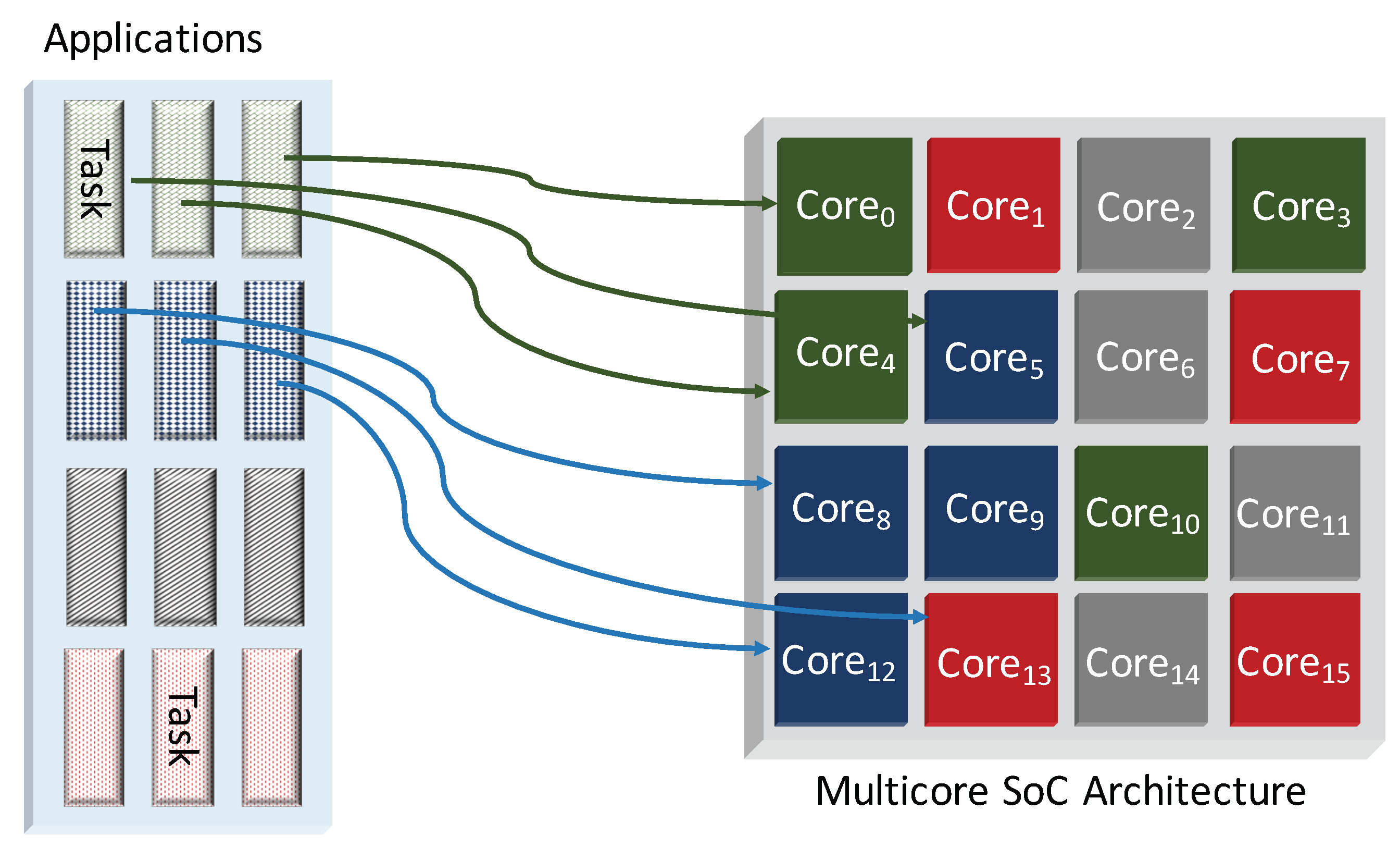
In current SoCs, the way to schedule tasks to processing nodes generally makes it difficult to reason about the runtime interactions between functions of different trust levels, especially in the absence of hardware-level support. This procedure often leads to ad-hoc execution modes where trusted or untrusted software could be running on both trusted or untrusted hardware. Figure 1 shows a set of applications with mixed security mapped onto mixed security hardware. Hermes achieves both hardware and software views of secure processing by grouping processors into physical zones called wards and virtual logical zones called islands.
First, the on-chip processing elements are divided into wards that are identified and formed at system integration time, based on IP or processing element provenance. Wards are created to help negotiate the security keys used to create the islands in a trusted manner. Because the security level is inherent to the IP origin, the wards remain constant throughout the chip’s lifetime. The chip is divided into physical quadrants, and, within each quadrant, nodes of the same security level make up one ward. Hardware security is divided into highly trusted, trusted, untrusted, and unknown levels. Each ward has a representative node/module, called the anchor node, specified and selected during system integration stage. The anchor node has a table containing the reachability and security information of the other anchor nodes and nodes in the same ward. Figure 2 shows the ward grouping of the illustrative mixed security heterogeneous architecture presented in Figure 1. The anchoring of wards provides a simple method of node discovery and key distribution without requiring a full list of node keys at each node.
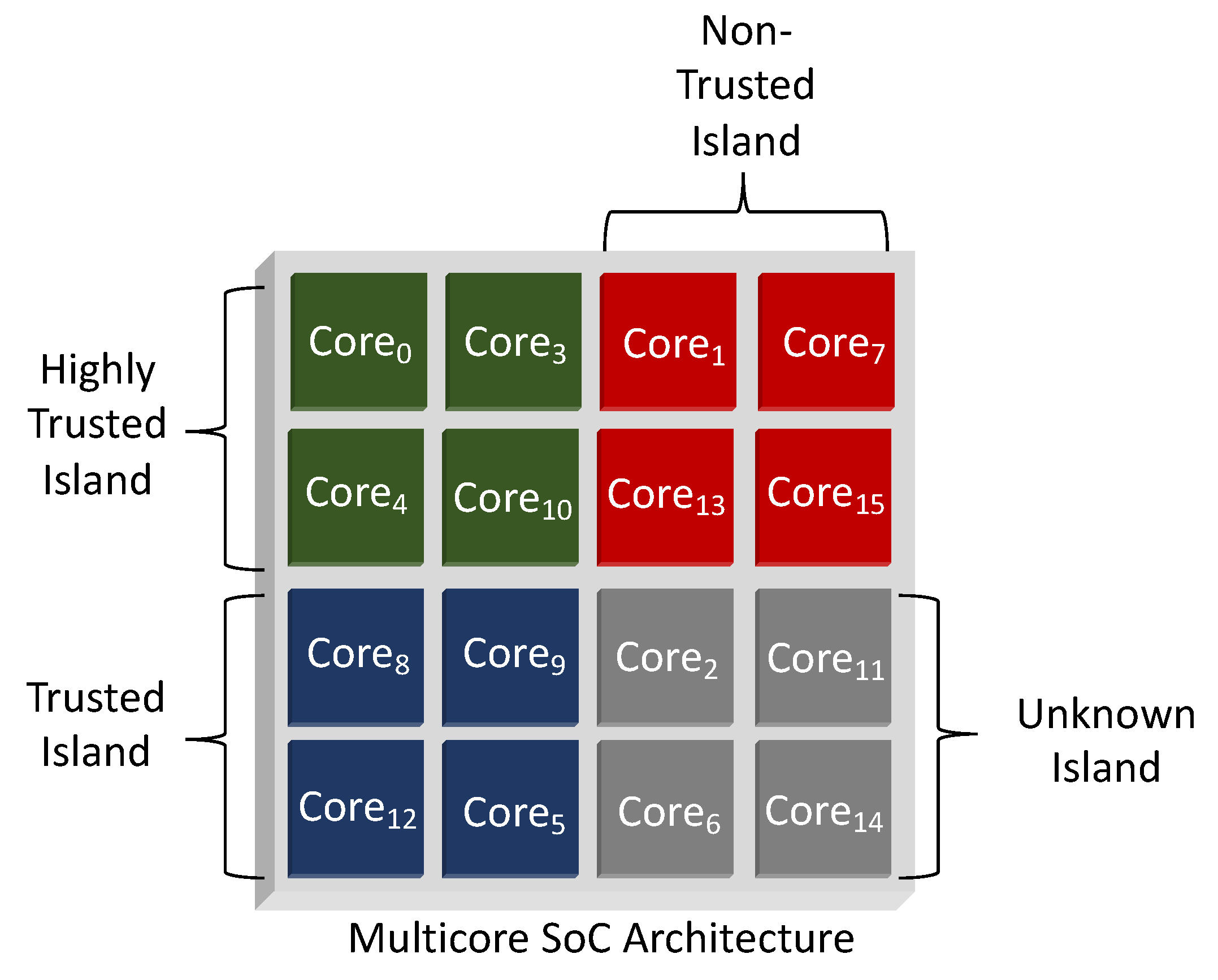
Second, the processing nodes of Hermes are virtually grouped into logical zones called islands based on their static or runtime security characteristics. These nodes can be either secure processors or non-secure processors, as well as any combination of hardware processing units with varying levels of trust. Figure 3 shows an illustration of a virtually partitioned view in the baseline multicore chip, based on the trust level. Kernel or user applications are assigned a security abstraction, trusted and untrusted, that creates four basic island security levels namely: (1) trusted hardware and software; (2) trusted hardware and untrusted software; (3) untrusted hardware and trusted software; and (4) untrusted hardware and software. Each node is assigned to an island based on the applications running on them and their IP trust credentials. Islands allow keys to be managed at runtime to maintain isolation, as tasks are moved between the processing units.
One of the key innovations of the Hermes architecture is that the physical wards and the virtual islands are decoupled, hence making the node placement decisions independent of the processing cores’ security needs. This allows for efficient on-chip routing and node grouping.
3.2. Enhanced Programmable Memory Access Management
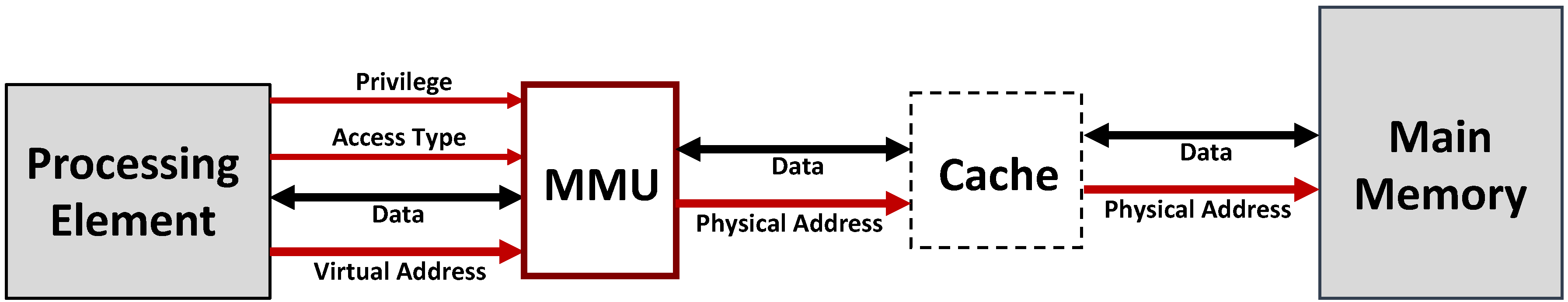
In multicore systems, the implementation of on-chip security policies is typically handled by the memory management unit (MMU) through: (1) application memory management; (2) operating system memory management; and (3) hardware memory management. The MMU is placed between the processing element and the memory subsystem where it translates virtual addresses into physical addresses and performs access right validations. All of the memory management safeguards, however, stop at the processing node boundary. Figure 4 shows the typical hardware memory arrangement.
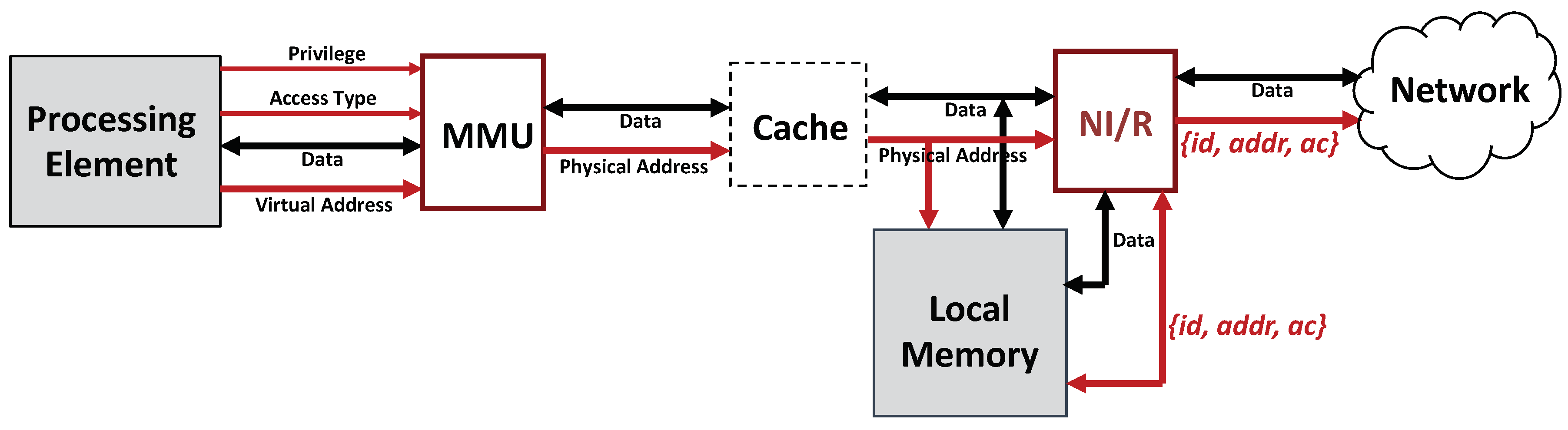
The Hermes design extends the MMU protections and security policies beyond the node boundary into the NoC layer while still applying conventional system memory management techniques at the node-level. The Hermes architecture is an interconnected network of nodes where the physical memory is distributed. A portion of the total on-chip memory is allocated to each processor node in a Non-uniform Memory Access (NUMA) style. Figure 5 shows the new enhanced system node organization. The MMU not only provides local memory protection guarantees for processing requests serviced at the node-level but also guarantees their secure routing when requests need to traverse the on-chip network by sending processor id and access code ac along with the messages.
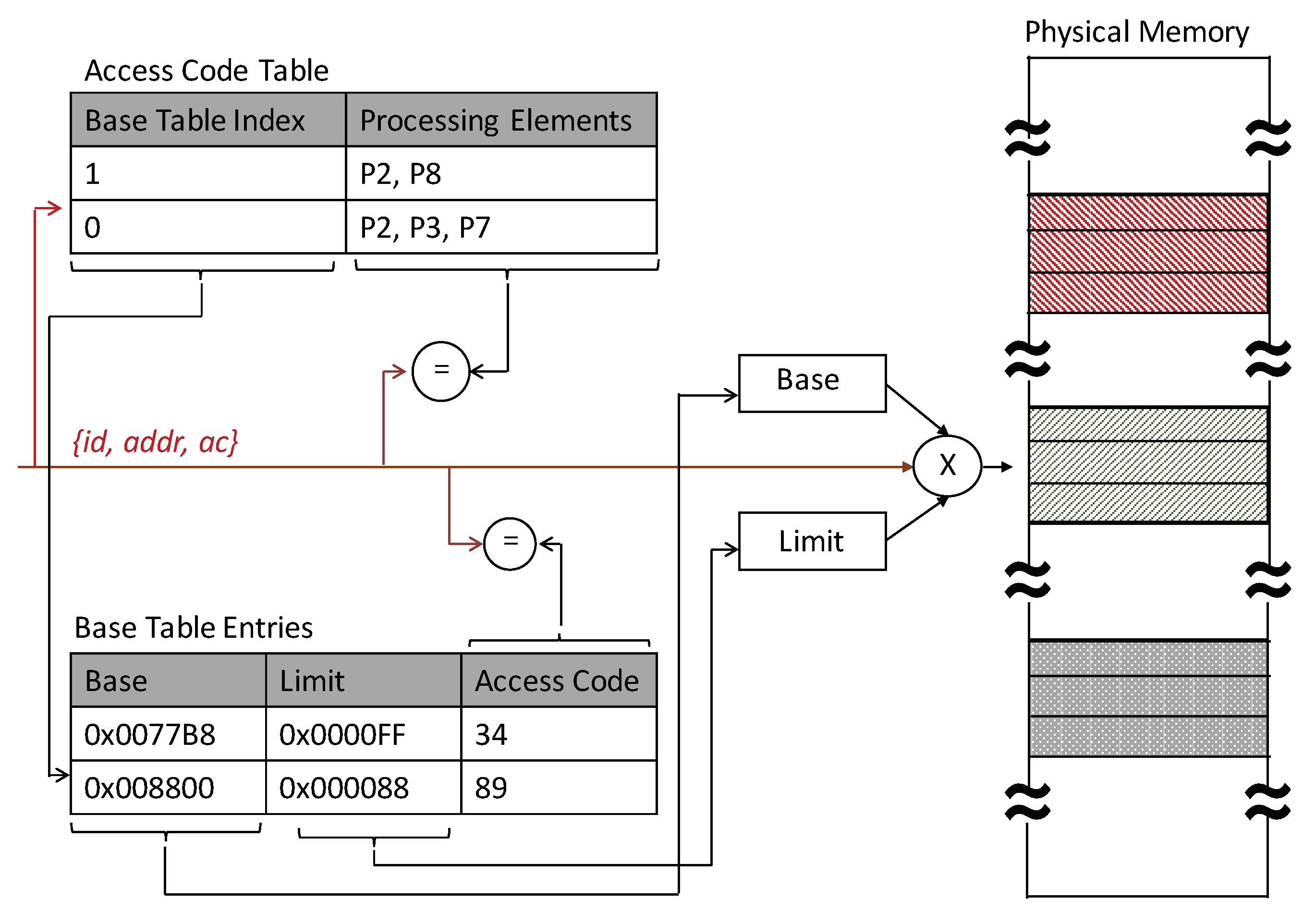
On a load or store miss at the processing element, the higher order bits in the address are used to locate the physical location of the memory block being addressed. During packetization at the source, the processing element id is added to the address and/or data with an access code (shorter version of island key). The packet is then encrypted using the island key or the destination master key. At the remote node, the security layer checks that the process or processor making the request belongs to the appropriate island. After depacketization, the local router sends the source PE id, the address, the access code (AC), and the data if it is a write operation, to the memory module. The lower bits of the address are used to index into the Access Code Table (ACT) to check that the PE is part of the island authorized to access the memory block. In parallel to this, memory boundaries and access code are fetched from Base Table (BT) to verify that the PE protection key matches the current access code value associated with the memory block being accessed. The AC, in addition to the Base and Limit registers, helps preserve forward and backward secrecy by being updated on changes in island membership, even over the same memory range. Figure 6 illustrates the memory access control logic.
4. Security Mechanisms: Distributed Island Key Management Approach
The Hermes system uses an efficient dynamic key management protocol to manage and isolate various trust levels with low hardware-overhead [14]. The protocol generates island keys based on the processing elements’ and applications’ trust levels.
For this type of distributed key management system, there are three general approaches for handling the distribution: (1) store the full list of public keys at each node; (2) store only neighbor’s key at each node; and (3) divide the nodes into clusters, where one node in the cluster stores the public keys of the other clusters, while the remaining nodes in the cluster only store the lead node’s public key. For practicality and security purposes, we implement the third approach: a distributed and coarse-grained method, where nodes only store certain public keys.
During application mapping, initial public keys are created using the Diffie–Hellman protocol. As the application data are placed onto the nodes, public keys are stored on anchor nodes. Each anchor node has a table containing the public key list of the other anchor nodes and the nodes in its ward. The notation for node keys is as follows: the public key of a node i is denoted , the private key is , and an island v’s key is represented as . Public requests and responses are denoted and , respectively. The process of dynamically creating, expanding and contracting islands happens through the join and leave operations.
The join operation protocol is used to add a node to an island or to create an island. An island is a set of nodes with access to a particular data block. When a new node needs access to a data block, it first must obtain the public key of an island member (referred to as its sponsor) and join the island before requesting access. The sponsoring node will verify the security level of the requesting node and, if the security is sufficient, will initiate the key update process and provide the new node with the island key. The full protocol is described below, assuming requesting node i is in anchor node x’s ward and the sponsor node j is in anchor node y’s ward.
Protocol 1.
The protocol of a new node conducting the join operation is as follows:
- 1.
- Node i sends an encrypted message to anchor node x requesting node j’s public key: . E and M denote the encryption operation and message, respectively.
- 2.
- Anchor node x sends an encrypted message to anchor node y requesting node j’s public key for node i (denoted ) including i’s public key: .
- 3.
- Anchor node y sends an encrypted message to node i using i’s public key containing node j’s public key for node i: .
- 4.
- Node i then sends an encrypted message to node j using j’s public key requesting to join the island assigned to the memory block at j: .
- 5.
- Node j verifies node i’s access code embedded in the key request message to determine i’s trust level. If there is no island, node j creates a symmetric key and sends it to i, . If there is an existing island, node j creates a new island key using a one-way function f such that . Node j sends the new island key to both i and j sponsors for the island to enable the propagation of updates. Node j also marks its island table to reflect i as a dependent node. When sponsor key update reply comes back, then j sends i the new key.
- 6.
- When node i receives the message, it updates its island table to make j its sponsor for the particular island.
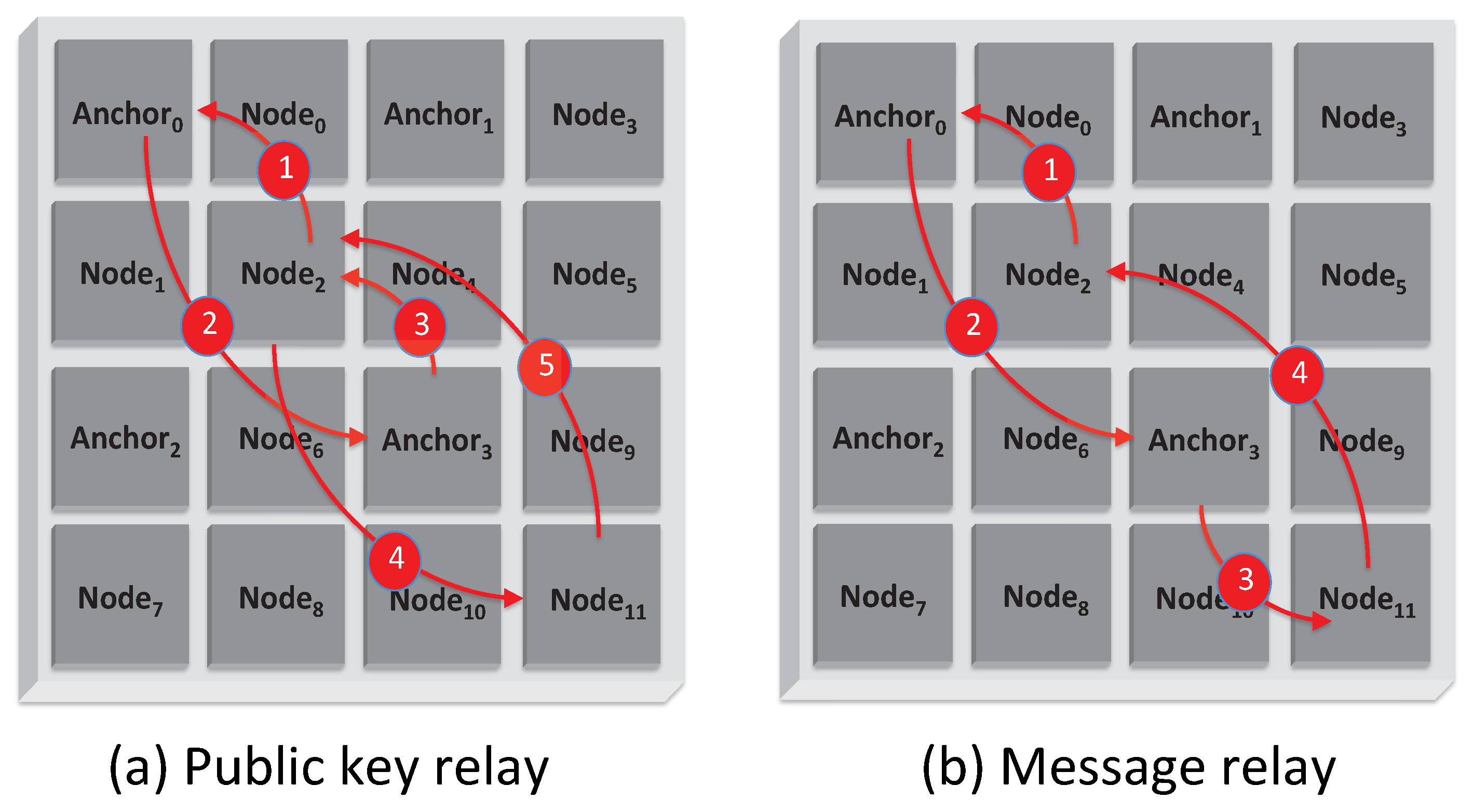
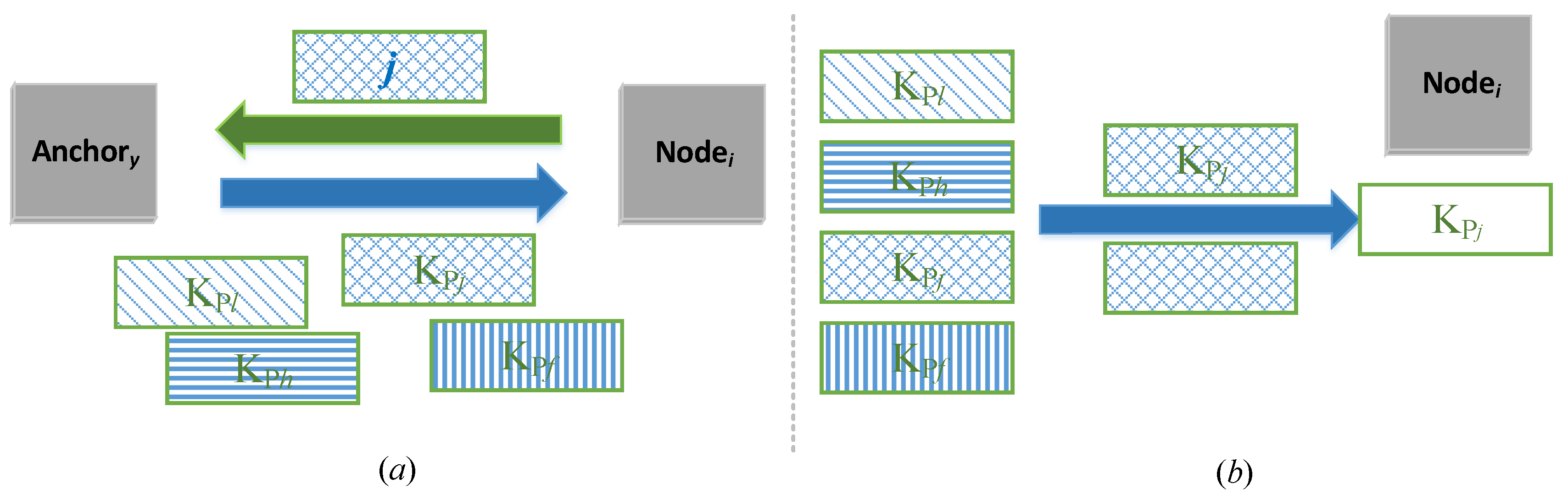
Figure 7 shows an illustration of the join operation. To cut down the number of messages for establishing or joining a new island, we add the message relay capability, where if two anchor nodes are at the same trust level, then the second anchor can directly send the island key request to the node in its ward, as shown Figure 7b.
Protocol 2.
The leave operation protocol is as follows:
- 1.
- Node i sends to node j, its sponsor for an island, a leave request. j sends the new island key to its node sponsor of the island for propagated updates. When the sponsor’s reply arrives, node j removes i from its island table and sends a reply to i.
- 2.
- When node i receives the message, it updates its island table for the particular island.
Islands dynamically change when certain execution events occur. For example, when a cache-miss involves a remote access and the processing node making the cache request is not part of the island holding access key to the memory block of interest. This event will lead to an island join operation. Dynamic task and thread scheduling, re-scheduling and load re-balancing may also activate idle nodes and create join operations. When tasks or threads finish or exit the system, these events may trigger leave operations.
Both join and leave operations may lead to a new island topology. In such cases, the routing connectivity graph of the island needs to be rebuilt and associated routing tables will need to be updated. During the re-keying process, network virtual channels are also reset to prevent VC plowing.
5. Untrusted Processing Element Tolerance and Privacy Preservation
Protocols 1 and 2 have provided a convenient and trustworthy approach to allow a node to join and leave a virtual island though physical wards and anchors. However, in this approach, an assumption is made that, although nodes have different trust levels, they will remain honest in the entire join and leave processes. This means that: (1) a node i will only apply for an island using an access code matching its trust level; and (2) a sponsor node j will verify the requesting node i’s trust level honestly and will not let in any of the disqualified nodes.
With any of the above conditions broken, there will be grave vulnerabilities in the system. For example, since the access code is a static string, any node who has knowledge of this code (by legal or illegal means) can request for an island key it does not deserve. Another scenario can be that a sponsor node j, say from an unknown island, treats its sponsorship with misconduct by letting in a node without a proper .
Additionally, there may also be a need that a requesting node wants to join and leave an island silently without being known by other nodes and even the anchor nodes, except a necessary sponsor. This applies particularly to the scenario when a highly trusted node has to join a lower trust-level island and it does not want to be listed as a potential sponsor. This invisible join ensures that its public key will not be requested by other untrusted nodes who also want to join the island.
In response to these vulnerabilities caused by dishonesty and the one demand in invisible join, we propose three corresponding solutions that enhance the join and leave protocol, particularly, Protocol 1. With these solutions:
- We can apply a dynamic access code fetching scheme, so that only the nodes properly being verified and applying for can present to its sponsor node a legal , which is also personalized for the requesting node.
- We can apply a threshold join authorization scheme, so that it takes more than one sponsor node to allow a join of a new node. Thus, even if one sponsor node is casual about the join request, other sponsor(s) can still hold the line.
- We can apply an invisible island join request scheme, so that a requesting node with a higher trust level can hide its lower trust-level destination from the anchor or any other nodes. The privacy of the node is preserved and it will not be listed as a potential sponsor in a lower trust-level island.
In other words, this section provides a strong protection to the key management approach in Section 4, under the assumption of dishonest entities’ existence. The protection scheme consists of three protocols to address the problems mentioned above.
5.1. Dishonest Requesting Nodes Tolerance—Dynamic Access Code (ac) Fetching
As introduced in Section 3.2, the access code is one of the key elements in the Hermes system. It is derived from the island key, and grants a node with the permission to access the block of data which matches the node’s trust level. The is usually static (shorter version of island key ) and remains the same to any node acquiring it. Its generation and storage are not privacy preserving. This means any node with this string will be able to make a request, and there is no particular protection approach to prevent nodes from re-using it without authorization.
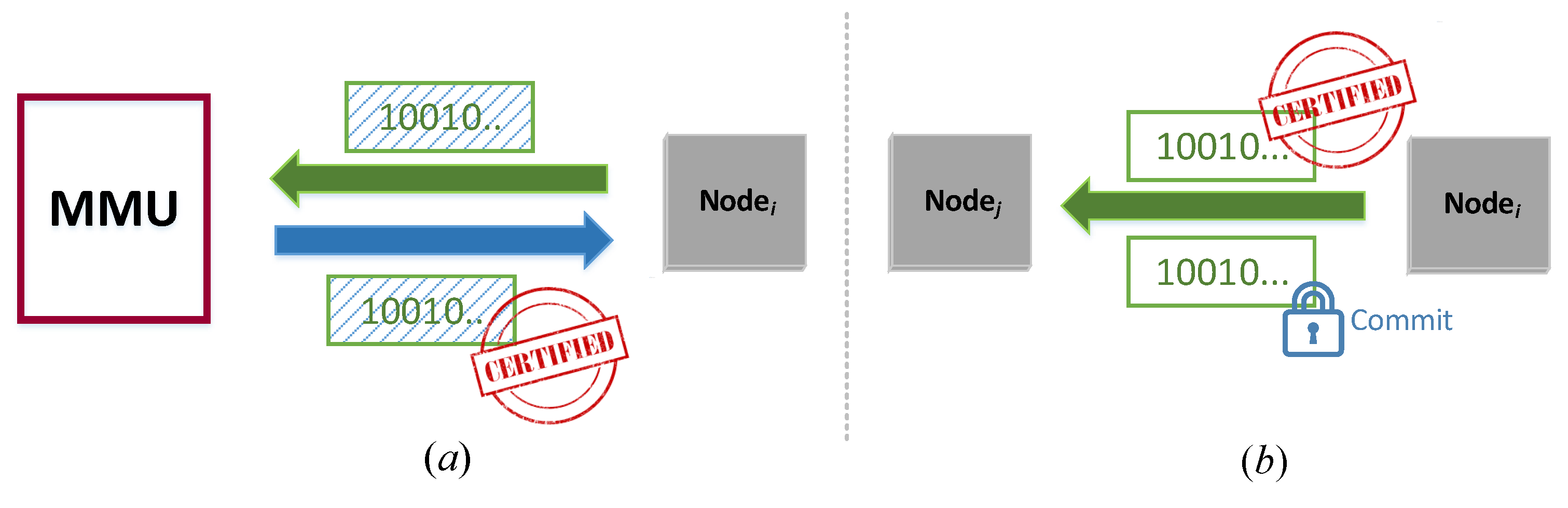
A desirable secure fetching would require that each node has to dynamically acquire a temporary (one-time) and personalized before its join request; this should be valid only once for this request. The basic idea is, when node i is authenticated and verified with its trust level, it needs to acquire a temporary , whose value is only known to itself. To do so, it will firstly send a masked string to the MMU, who will sign the masked string. Then, i will remove the mask without destroying the MMU’s signature. The signature and a proof of knowledge of the string will be sent to its prospective sponsor j for verification.
The figurative illustration of the procedure is shown in Figure 8.
Protocol 3.
Inspired by the compact e-cash [15] scheme, we propose the following protocol for the dynamic fetching.
- 1.
- Node i firstly proves its authenticity and trust level to the MMU through authentication (i.e., secret key or PUF authentication etc.).
- 2.
- Node i selects an arbitrary string x, computes its commitment . For simplicity, a commitment here can be considered as a one-way hash.
- 3.
- Node i selects a masking function , such that leaks zero knowledge of x. In addition, there exists a function such that .
- 4.
- Node i shows to the MMU. The MMU signs it with function and returns it to the device. In addition, there exists a function that . This function is known by all the current island members.
- 5.
- At the time of the join request, node i applies , which is the temporary , and sends together with to node j.
- 6.
- Node j applies , and verifies if:If so then node j agrees to be the sponsor of node i.
- *
- (Note: The functions can be generated by the Carmichael’s totient function, similar to the RSA key generation algorithm.)
In this way, the is dynamically generated and no longer a reusable string. Consequently, the Access Code Table (ACT) is replaced by the verification of , which carries out the same task to check that the PE is part of the island authorized to access the memory block.
5.2. Dishonest Sponsor Tolerance—Threshold Join Authorization
In Protocol 1 Step 5, node j, the prospective sponsor, needs to first decrypt , and then check node i’s . Upon the verification of the embedded in , node j determined whether to send the new island key to node i.
Although in Section 5.1 Hermes ensures the proper fetch of , if a sponsor node j is not honest, then it could let in any node with or without a qualified . This might not happen among the sponsors on the highly trusted islands or trusted islands. However, it is possible among the untrusted or unknown ones in Figure 3.
Therefore, we propose a dishonest sponsor tolerance scheme that does not put the trust on a single sponsor. Instead, it takes the permission from multiple sponsors to enable the join operation. In this scheme, we set a threshold t where node i must acquire the permission from no less than t of any sponsor nodes in the desired island. Less than this threshold, node i is unable to join.
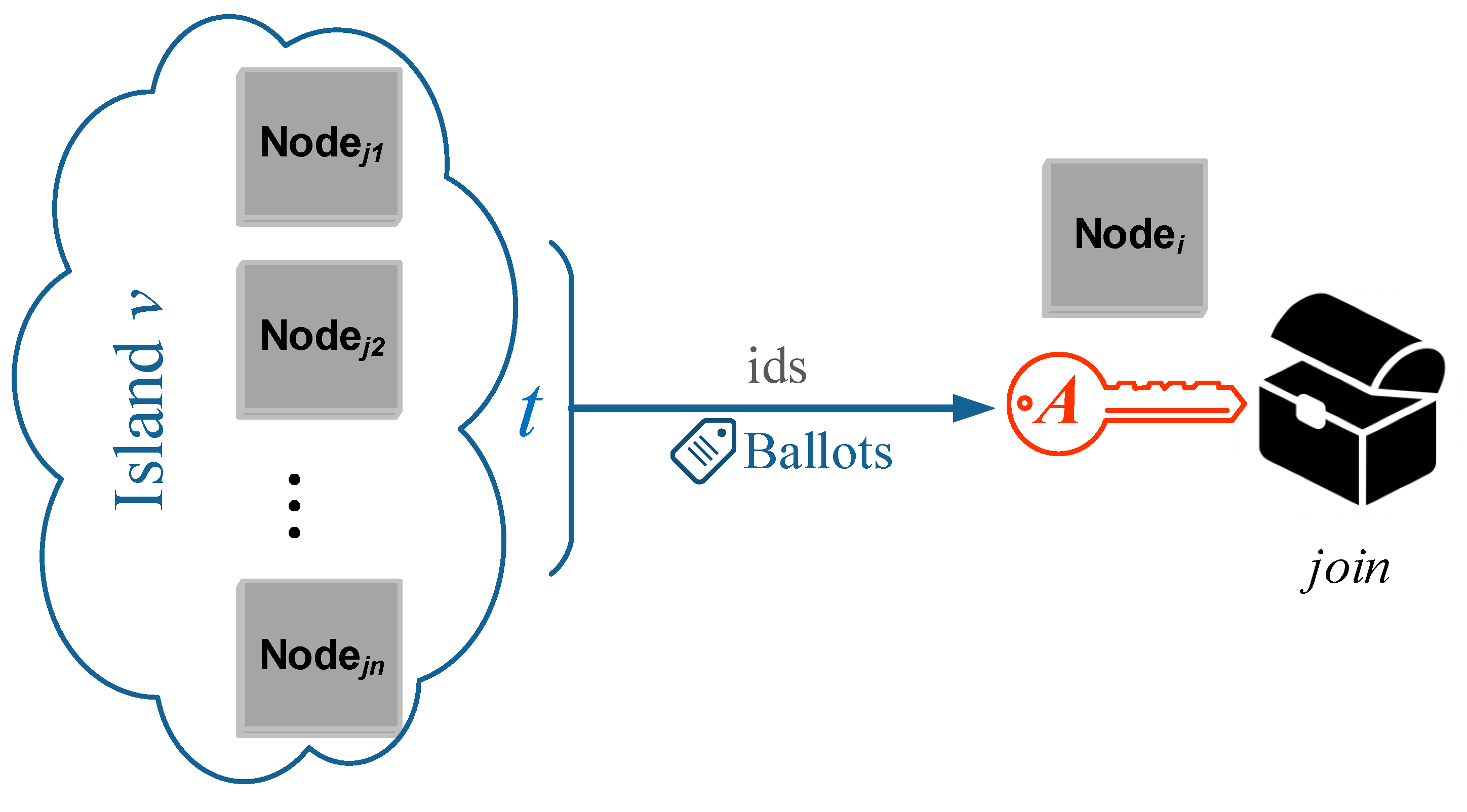
Such a group decision approach has been proposed by a number of researchers [16,17,18]. Briefly speaking, to gain the access to the desired island, node i must acquire an authorization token A. In that island, each of the existing nodes holds its own id and a ballot, which is computed by Shamir’s secret sharing equation based on A and its id. After verifying the in node i’s request message, the prospective sponsors who agree to grant i the island key will send their ballots to i, and those who do not agree will not. Node i needs to collect at least t ballots to retrieve A to prove its qualification for .
Figure 9 depicts the voting procedure:
Protocol 4.
The threshold island key authorization protocol with dishonest sponsor tolerance has two stages:
- 1.
- Ballot Distribution:
- (a)
- For an authorization token A at an island, its commitment is made publicly known to all existing nodes;
- (b)
- Denote node j’s id as , then node j’s ballot is computed by:where all the coefficients of a can be arbitrarily chosen.
- 2.
- Threshold Voting:
- (a)
- Node i has to contact t prospective sponsors, who will verify its (some dishonest sponsors may not). Only the sponsors who agree to let i join will send their ballots to i. If there are at least t sponsors supporting the decision, then with the Lagrange interpolation formula:the authorization token A can be reconstructed by node i. If there are less than t supportive voters, then A remains unknown to i, meaning the join request is denied;
- (b)
- Node i computes and proves to all the sponsors it reaches the qualification threshold. Then, the island key will be granted by any of the supportive sponsors.
- (c)
- Once i joins the island, it will hold its ballot as a potential sponsor too.
Equations (2) and (3) are the share distribution and secret reconstruction equations of the t-threshold secret sharing (TSS) scheme, which was first introduced by Shamir [19] and later studied by many researchers. With this technique, the probability of letting in disqualified nodes by dishonest or unfaithful sponsors is drastically reduced. For example, at an unknown trust level island where , a dishonest sponsor decides to casually give its ballot to node i, whose is disqualified. Another sponsor checks the faithfully and decides not to support the join of i. Then, without enough ballots, information of A remains unknown to node i. Thus, i cannot acquire by showing .
5.3. Invisible Island Join
In these heterogeneous SoC architectures, the attacker needs to first identify the victim node before devising an attack scheme. Consequently, any degree of node identity obfuscation will harden the system’s security posture. Concretely, in cases where a highly trusted node i wishes to join an untrusted or unknown island, it may be favorable if its privacy can be preserved when communicating with other lower trust-level nodes and even the anchor nodes who have introduced i to its sponsor j. In a sense, node i would enter an “incognito” mode.
For security purposes, we only allow trusted and highly trusted nodes to have this invisible island join feature. This feature allows a node i to hide its destination from the anchor who introduces it to the sponsor j, while still getting the public key of j from the anchor, so that in the entire network, only j knows the join of i.
The brief idea is to make the public key request in an oblivious manner. In Protocol 1 Step 1, instead of putting the in the request message, i uses an obfuscated message which does not reveal j’s identity. In step 3, anchor y responds also with obfuscated public keys of all the nodes in its ward. Then, i is only able to retrieve j’s public key but not others.
Figure 10 depicts the invisible join procedure:
Protocol 5.
The invisible join protocol is as follows:
- 1.
- When node i wants to have j as its sponsor, it firstly notifies anchor y through anchor x that it requests for one of the public keys anchor y holds;
- 2.
- Suppose anchor y has m nodes in its ward. It generates m random vectors with the same length of the public keys;
- 3.
- Anchor y has two numbers that mod (). Again, this pair can be generated by the Carmichael’s Totient function in the field of N. Anchor y sends e together with the m random numbers to i, while keeping d to itself privately;
- 4.
- Particularly, i wants to connect with j, so i generates the following vector:where T is a random vector;
- 5.
- On receiving u through anchor x, anchor y calculates:for all .
- 6.
- Anchor y sends all these m messages to i:for all .
- 7.
- Node i computes:
- 8.
- In this way, node i acquires the public key of node j in the desired island. All other public keys remain unknown to i, and the identity of j is unknown to all other nodes including the anchor nodes, except j itself.
This protocol leverages the 1-out-of-n oblivious transfer (OT) [20,21] which provides invisibility of node i’s join into j’s island. This way i stays unlisted from the sponsor list and even anchor nodes x and y in the join Protocol 1 do not know where it has joined. Thus, i’s public key will not be requested by other low trust level nodes who want to join the island.
6. Hermes Architecture Support
The design methodology behind the Hermes architecture is to provide hardware-supported mechanisms for user-defined or software-defined security rules and their enforcement in heterogeneous multicore systems-on-chip. It effectively decouples the security or trust level management of processing cores from the integrated SoC.
6.1. Hardware-Support Implementation
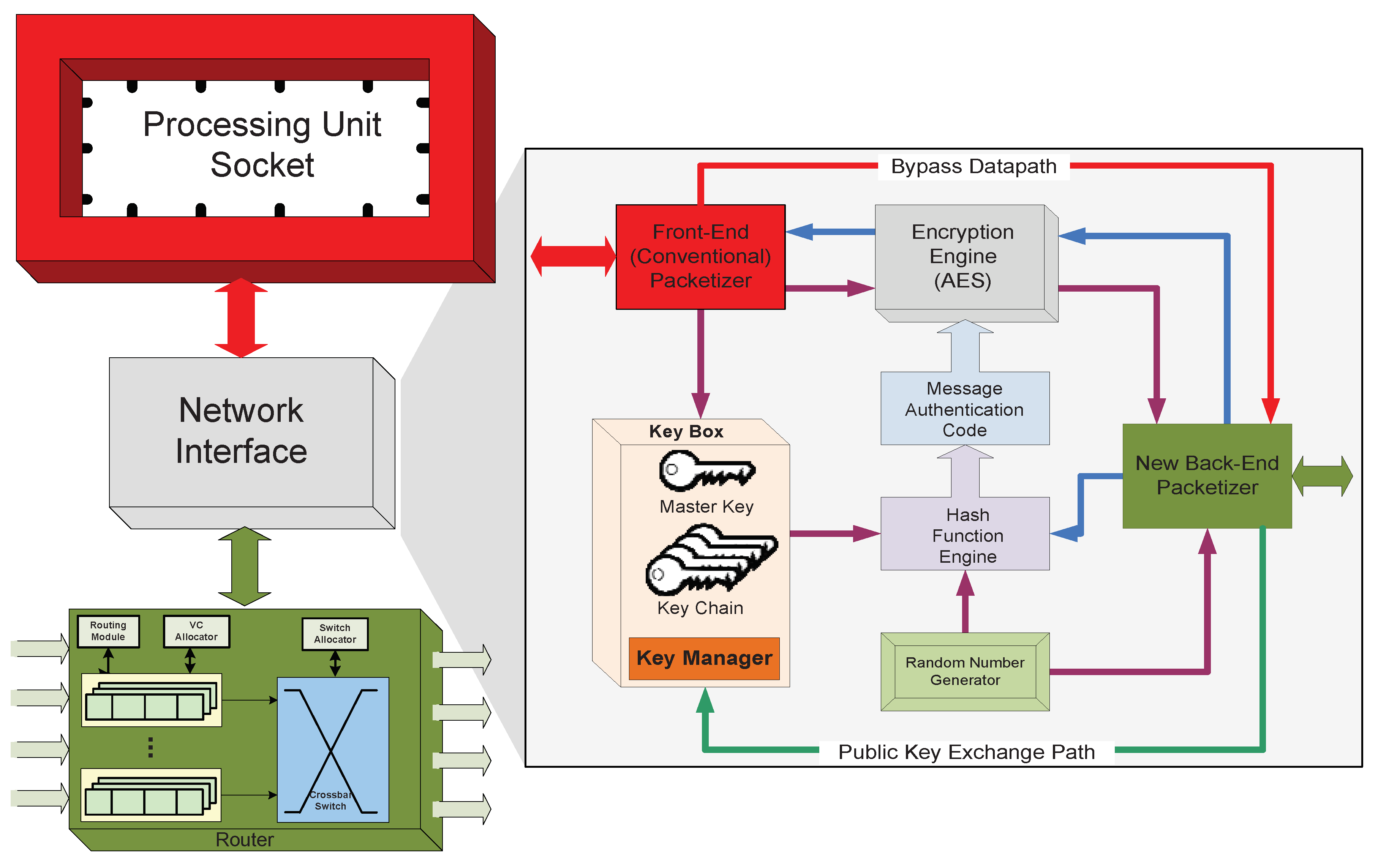
The hardware template depicted in Figure 11 can be described as the high-level node module of the Hermes architecture. Each processing node has: (1) a processor socket to support integration of third party processing IPs; (2) a network interface module supporting our novel secure computing protocol; and (3) a virtual channel router. A major contribution of this work is the complete decoupling of the system level fine-grained security management scheme from the processing elements (cores or tenants) and executing software security level. Any processing unit executing any type of software can be installed in the processor socket. Similarly, our security and trust models are oblivious to the on-chip network router microarchitecture.
The hardware modification is constrained to the Network Interface (NI) module. The NI is responsible for converting data traffic coming from the local processor and cache subsystem into packets/flits that can be routed inside the network, and for reconstructing packets/flits into data traffic at the opposite side when exiting the NoC. The new network interface has two datapaths: one encrypted and one bypass. The encrypted datapath’s functional block description is provided in Section 6.2. The Bypass path through the NI module enables the disabling or power-gating of the encryption function at a given core site.
6.2. Communication Protocol
Hermes is an encryption-based secure architecture. Its communication protocol is as follows:
- A local processor unit generates message traffic consisting of memory load and store operations, cache coherency messages and inter-core communication traffic.
- The Front-End Packetizer converts the processor produced data traffic into packets that can be used for communication with the Network Interface (NI).
- The appropriate communication key is selected by the Key Manager in the NI. All of the keys are stored in the Key Box, which also contains the Key Manager function block. There is a single master key per processing site stored in the Key Box. The set of all the other keys is referred to as the Key Chain.
- The message authentication code (MAC) is generated by feeding the key and one random number into the Hash Function Engine. MAC is used as session encryption key, so that even the same core-pair can have multiple distinctive communication sessions.
- The processor generated packets are fed into the Encryption Engine with the MAC to be encrypted. We implement AES key encryption algorithm for the actual encoding of packets, given its low hardware logic cost.
- The Encryption Engine uses the MAC as a key to encrypt the data using the AES algorithm.
- The encrypted packet and a second random number are re-packetized by the Back-End Packetizer.
- On the receiving side, packets are first depacketized into encrypted packets and random numbers. The random number is used with the communication key to generate the MAC used to decrypt the packet. The blue directional edges in Figure 11 show the return side data-flow.
6.3. Trust-Aware On-Chip Routing Algorithm
The on-chip routing is also aware of the logical security islands and tries to either prohibit or limit the traversal of zones by non-member generated traffic. Algorithm 1 describes the added routing function.
| Algorithm 1: Trust-aware on-chip routing algorithm. |
 |
6.4. Illustrative Example
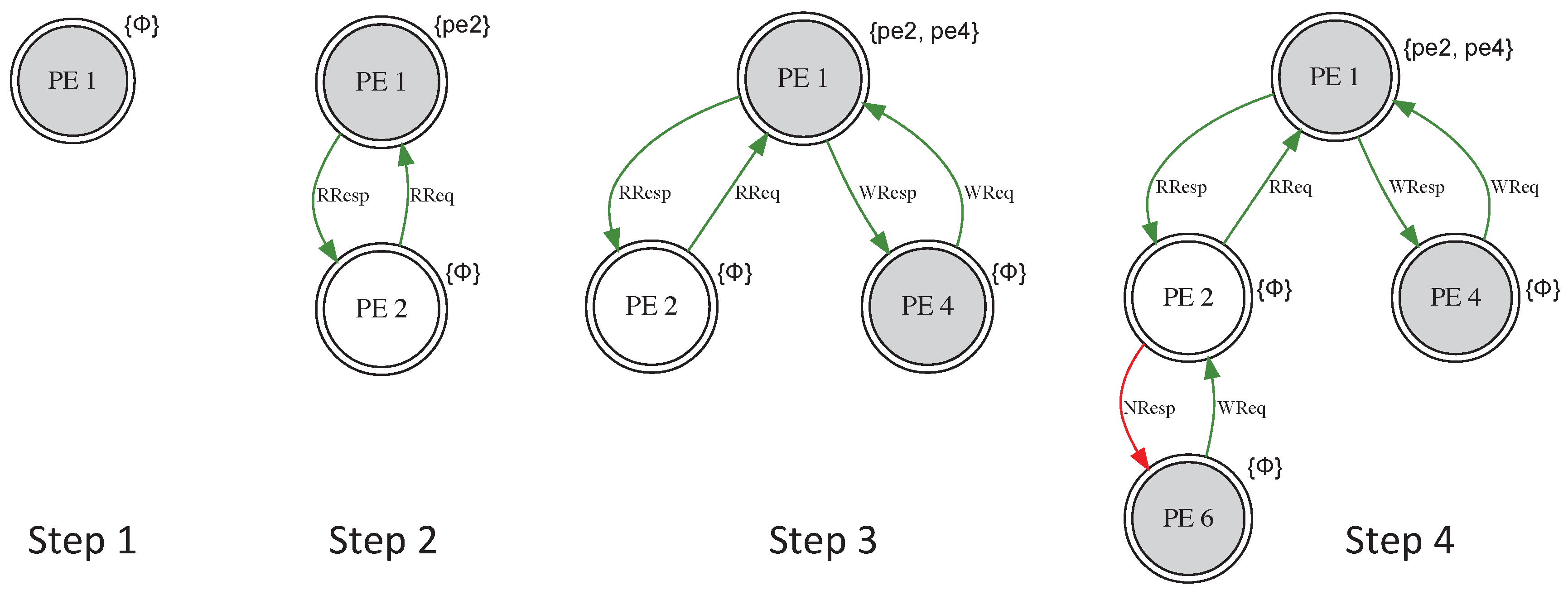
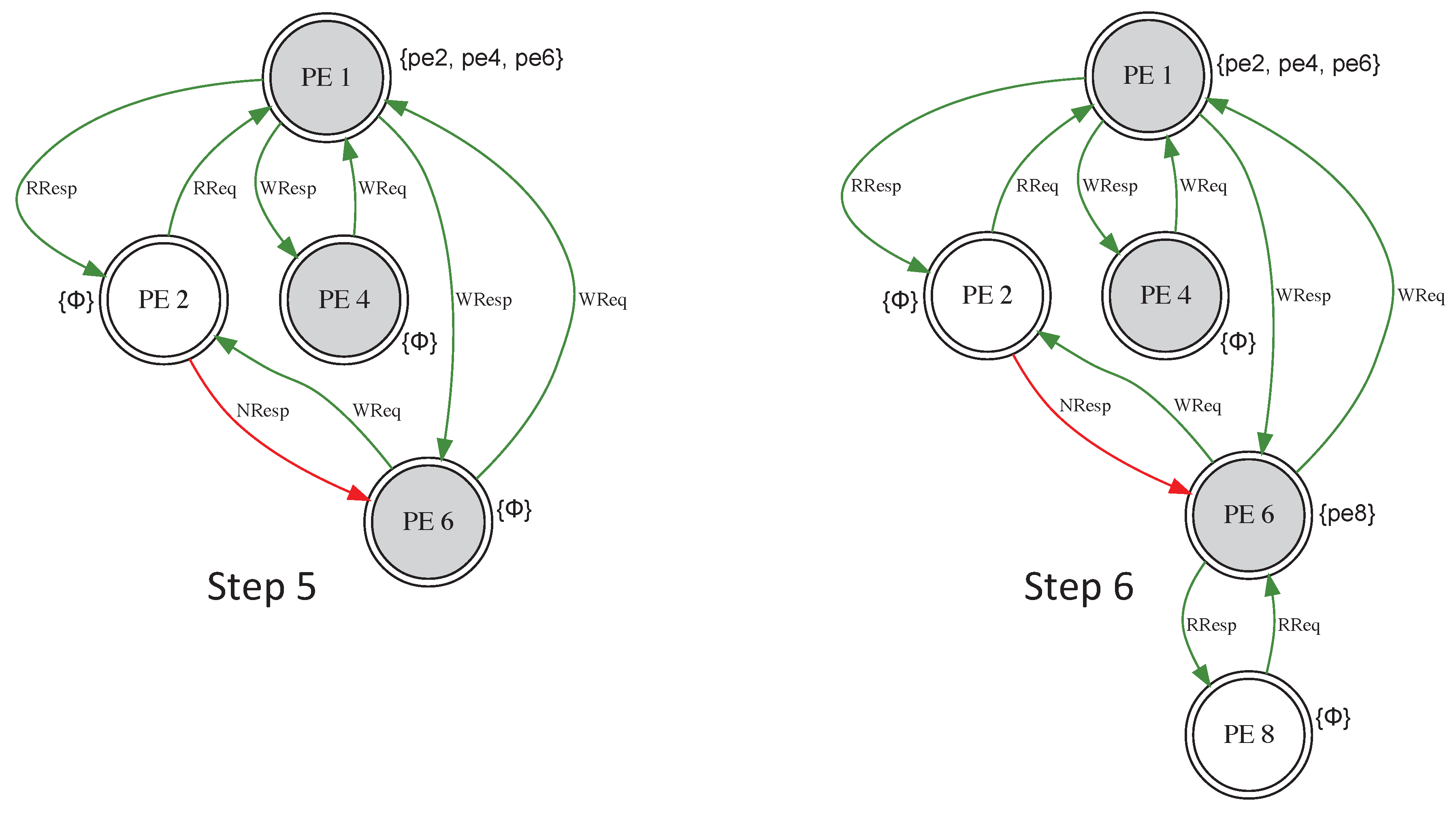
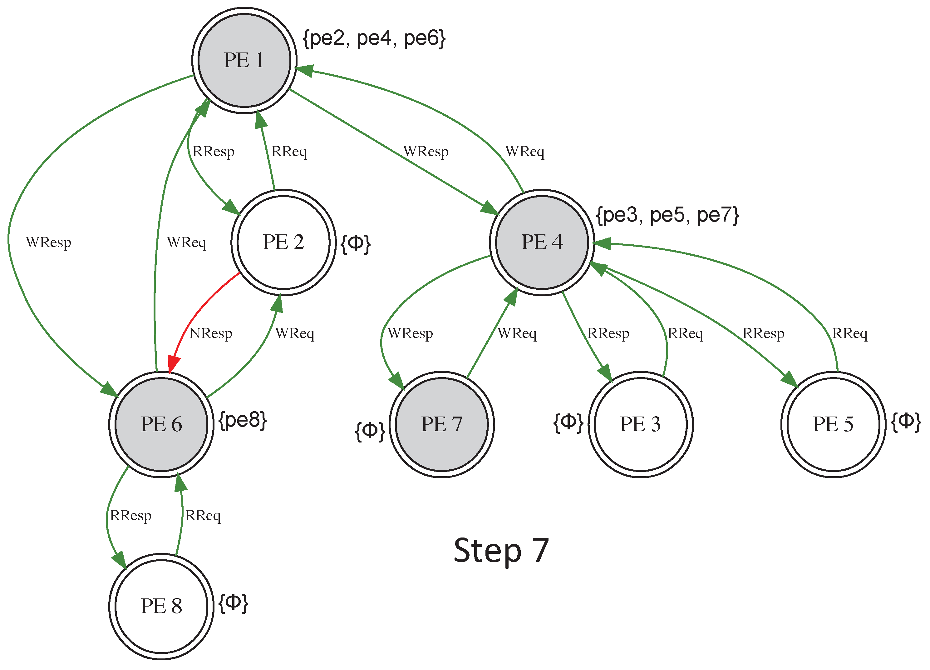
Figure 12 and Figure 13 show the case where the data placement for an application task and read and write operations dynamically create a security group. The initial placement is shown in Step 1. The effect of a read-only request from PE 2 is presented in Step 2. A read/write request from PE 4 causes the group to expand (Step 3). In Step 4, an attempt to read/write by PE 6 through PE 2 fails (red edge), since PE 2 cannot be a sponsor. Sponsorship consists of authorizing other threads/tasks/processes to read or write a copy of data without informing the initial owner. Consequently, PE 6 had to join the security group through PE 1 (Step 5). In Step 6, PE 8 is able to join the group through PE 6 and bypass PE 1’s sponsorship.
As shown in Figure 14, PE 1 has no record of the sharing between PE 3, 5, 7 and PE 4. This is done to avoid updating the whole group structure on every entry or exit. Therefore, the control of the security policies becomes distributed. Changes are more localized and the protocol is more resilient to notification propagation delay associated with group membership alterations. The evaluations show that this distributed approach is more scalable than the full broadcast scheme with equal security guarantees.
7. System Performance Evaluation
The effectiveness of the protection provided by the Hermes architecture to the attack models outlined in Section 1.2 is measured through flows and processes isolation. Strict isolation of flows and processes based on trust levels effectively creates control access to shared resources: (1) shared memory regions in the network, i.e., virtual channels at the router; and (2) distributed shared main memory modules. The degree of process isolation provided by Hermes inversely corresponds to the computing system attack surface, where higher isolation means smaller attack surface.
For the system performance and evaluation, an 8 × 8 2-D mesh topology design is implemented on a Xilinx Virtex7-XC7VX690T FPGA device. The board has LUTs and register slices. The unmodified switch allocation step in the routing process has the critical path due to the arbitration scheme logic. The operating frequency is MHz across all the designs. For the power estimates, the Xilinx Power Estimator (XPE) in the Vivado Design Suites is used. The power numbers are the post-routing estimates using a vector based switching activity format (i.e., SAIF). The process feature was set to maximum, the airflow to 500 LFM and the power supply to default.
The router has four virtual channels and eight slots per virtual channel. The Heracles [22] RTL simulator is used for all the experiments. Heracles’ injector cores are used to create network and memory traffic. Table 1 shows the FPGA synthesis results. In the table, BA stands for baseline architecture—Heracles’ seven-stage in-order RISC processor, AES is the 128-bit version and KS stands for key storage unit. The hardware overhead to fully implement the security features of Hermes architecture is only 17%. Table 2 has the power estimates for the different design. These estimates correlate fairly well to the logic resource utilization.
Since the secure Protocols 1 and 3–5 are all based on cryptographic operations, the number of exponential operations (exp op) can be used to evaluate the computation complexity and overhead. Table 3 shows the exp op of the Hermes join Protocol 1, and the overhead needed for the three secure schemes in Section 5.
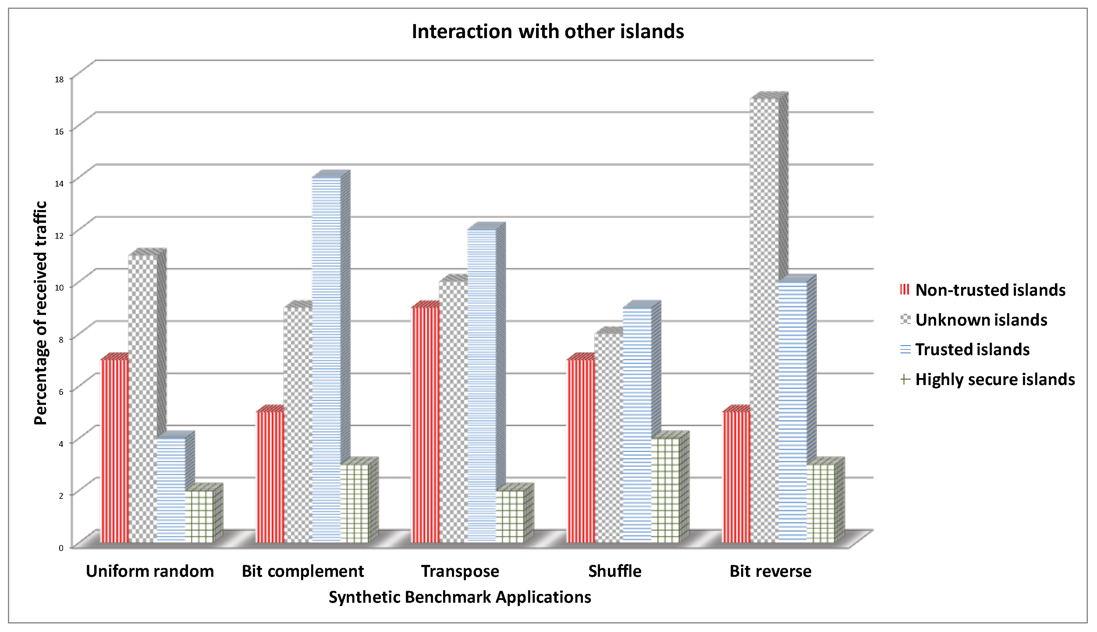
The trust level per core is randomly assigned. The synthetic benchmarks, Uniform random, Bit complement (BitComp), Shuffle, Transpose, and Bit reverse (BitRev), are used for the various evaluations. Figure 15 shows the interactions among the different traffic classifications. For example, in the Uniform random benchmark, less than 2% of the highly secure traffic is interacting (i.e., sharing a physical link or buffer space or memory block) with other types of traffic. The limited interaction reduces the attack surface and ensures greater security.
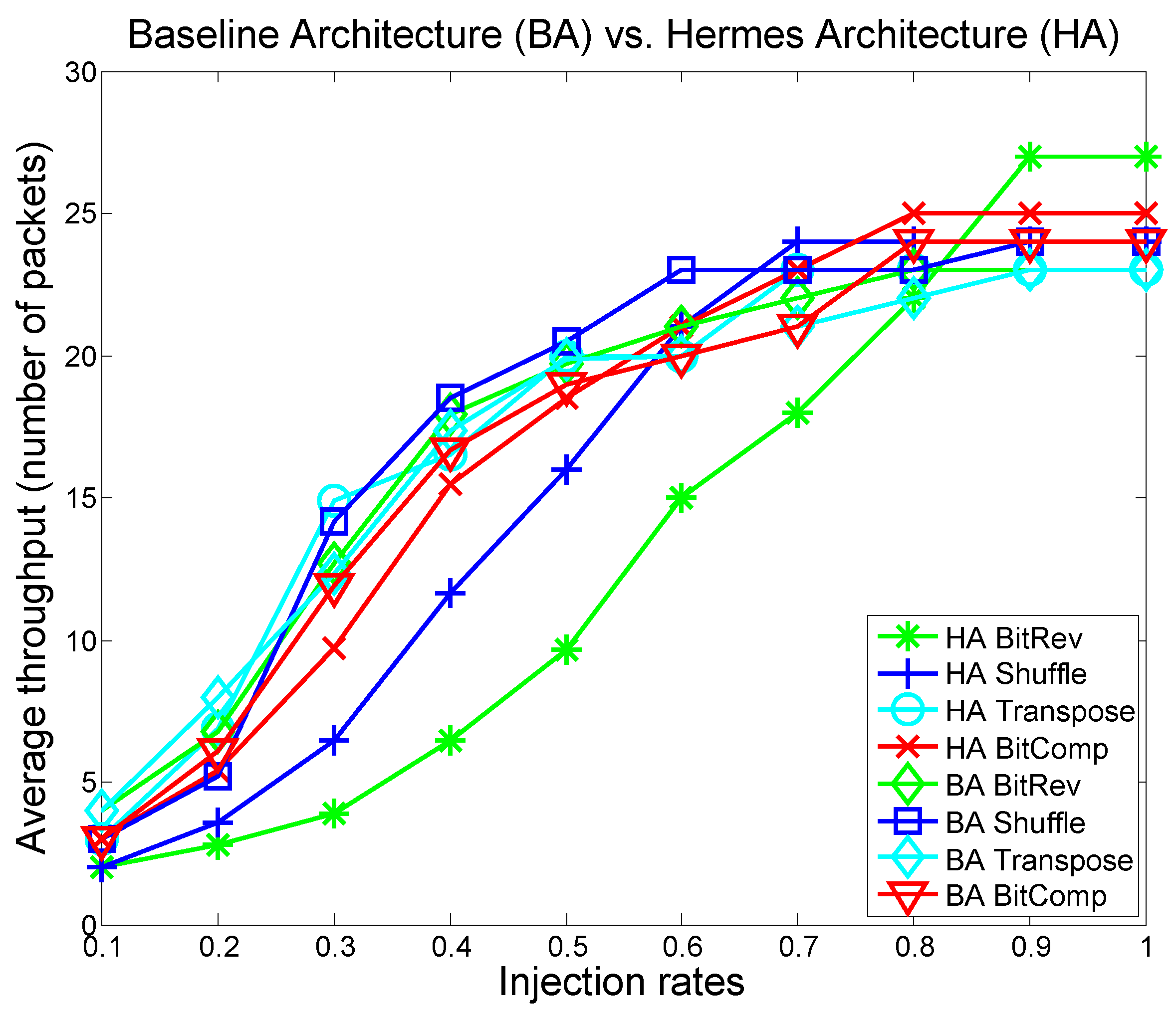
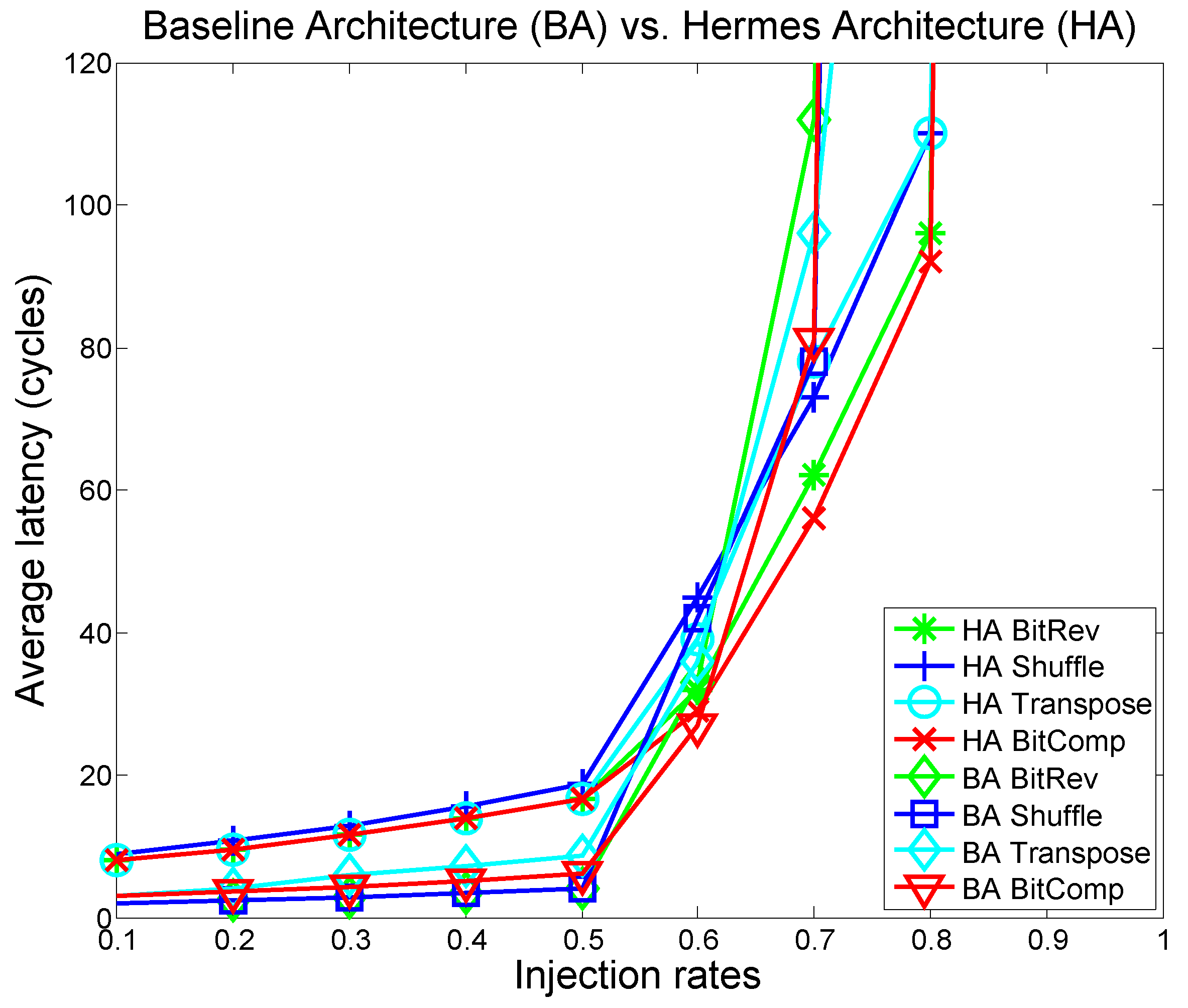
Figure 16 and Figure 17 show throughput and latency results of all the synthetic benchmarks on the baseline and Hermes architectures. The graphs are color-coded to match the trust-level (e.g., HA BitRev green means that the Bit reverse traffic is run in the highly secure mode). Overall, the proposed secure architecture shows no significant performance penalty. In some cases, we actually see a performance improvement at higher injection rates. This improvement occurs because the Hermes architecture tries to confine the traffic to their trust classification islands, which decreases path diversity and throughput for low injection rates but reduces head-of-line-blocking at high injection rates. In other words, by maximizing within-island routing, as a secondary effect, the algorithm also provides better traffic distribution and load balancing in the network.
In addition to the synthetic benchmarks, applications from the SPLASH-2 benchmark suite are used to evaluate the Hermes network performance and security enforcement. SPLASH-2 [23] is a diverse pool of applications commonly used to test and evaluate an architecture or a microarchitecture feature performance in a shared memory setting. These applications are simulated as traces. The Graphite [24] distributed x86 multicore simulator is used to generate the traces. Figure 18 shows the throughput results for the Hermes architecture on the SPLASH-2 benchmarks as fractions of throughput on the baseline architecture. The performance decline is only 1% to 9% across all the benchmarks when compared to the non-secure baseline architecture.
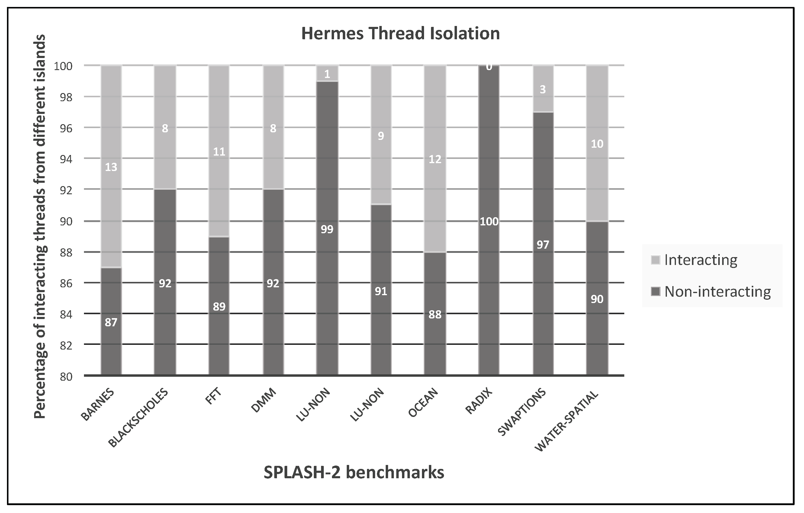
Figure 19 shows the degree of interaction among traffic for the different applications, measured as percentages. For these results, 25 placements (of processes and data) and simulations are performed and the best results are reported. Non-interacting means that flows from the application are routed within the routers assigned to the application without needing to use other applications’ island or local memory.
8. Conclusions
To solve the problem of mixed security of software and hardware components, we develop: (1) Hermes, a generalized multi-tenant, multicore computer architecture with virtual logical zones to enforce trust levels; (2) a dynamic key management protocol that lends itself well to the architecture for secure efficient heterogeneous computing; and (3) a set of schemes to detect and tolerate dishonest processing elements (PEs) in the island join procedure, while supporting privacy preservation for the trusted PEs.
Hermes isolates flows and processes based on their trust levels, effectively creating system-level control access to shared resources: (a) shared memory regions in the network, i.e., virtual channels at the router; and (b) distributed shared main memory modules. In the various sub-parts of the system, the architecture monitors processing traffic to verify their compliance to the trust level security policy in effect. The Hermes design model is currently limited to offline classification of programs and processing elements. In addition, the set of rules governing the mapping of programs to cores must be defined beforehand. The architecture has no runtime learning and classification of threats or trust level re-assignments.
Author Contributions
Conceptualization and methodology, M.A.K.; Security protocol and methodology: L.B.; Data Analysis: M.I.; Writing—Original Draft Preparation, M.A.K. and L.B.; Writing—Review & Editing, M.I. and M.M.
Funding
This research was partially supported by the NSF Grant No. CNS- 1745808.
Acknowledgments
We sincerely thank Joseph Mohr, Shreeya Khadka, Brian Gravelle and Anam Farrukh for their help in exploring earlier versions of the work.
Conflicts of Interest
The authors declare no conflict of interest.
References
- Oberg, J.; Sherwood, T.; Kastner, R. Eliminating Timing Information Flows in a Mix-Trusted System-on-Chip. IEEE Des. Test 2013, 30, 55–62. [Google Scholar] [CrossRef]
- Tehranipoor, M.; Koushanfar, F. A Survey of Hardware Trojan Taxonomy and Detection. IEEE Des. Test Comput. 2010, 27, 10–25. [Google Scholar] [CrossRef] [Green Version]
- Chen, Q.A.; Qian, Z.; Mao, Z.M. Peeking into Your App Without Actually Seeing It: UI State Inference and Novel Android Attacks. In Proceedings of the 23rd USENIX Conference on Security Symposium, San Diego, CA, USA, 20–22 August 2014; pp. 1037–1052. [Google Scholar]
- Jerger, N.E.; Peh, L.S. On-chip networks. Synth. Lect. Comput. Archit. 2009, 4, 1–141. [Google Scholar] [CrossRef]
- Fiorin, L.; Silvano, C.; Sami, M. Security Aspects in Networks-on-Chips: Overview and Proposals for Secure Implementations. In Proceedings of the 10th Euromicro Conference on Digital System Design Architectures, Methods and Tools (DSD 2007), Lubeck, Germany, 29–31 August 2007; pp. 539–542. [Google Scholar]
- Wang, X.; Tehranipoor, M.; Plusquellic, J. Detecting malicious inclusions in secure hardware: Challenges and solutions. In Proceedings of the 2008 IEEE International Workshop on Hardware-Oriented Security and Trust, Anaheim, CA, USA, 9 June 2008; pp. 15–19. [Google Scholar]
- Tiwari, M.; Wassel, H.M.; Mazloom, B.; Mysore, S.; Chong, F.T.; Sherwood, T. Complete Information Flow Tracking from the Gates Up. SIGARCH Comput. Archit. News 2009, 37, 109–120. [Google Scholar] [CrossRef]
- Hwang, J.Y.; Suh, S.B.; Heo, S.K.; Park, C.J.; Ryu, J.M.; Park, S.Y.; Kim, C.R. Xen on ARM: System Virtualization Using Xen Hypervisor for ARM-Based Secure Mobile Phones. In Proceedings of the 2008 5th IEEE Consumer Communications and Networking Conference, Las Vegas, NV, USA, 10–12 January 2008; pp. 257–261. [Google Scholar]
- Wassel, H.M.G.; Gao, Y.; Oberg, J.K.; Huffmire, T.; Kastner, R.; Chong, F.T.; Sherwood, T. SurfNoC: A Low Latency and Provably Non-interfering Approach to Secure Networks-on-chip. In Proceedings of the 40th Annual International Symposium on Computer Architecture, Tel-Aviv, Israel, 23–27 June 2013; ACM: New York, NY, USA, 2013; pp. 583–594. [Google Scholar]
- Sajeesh, K.; Kapoor, H.K. An Authenticated Encryption Based Security Framework for NoC Architectures. In Proceedings of the 2011 International Symposium on Electronic System Design, Kochi, India, 19–21 December 2011; pp. 134–139. [Google Scholar]
- Porquet, J.; Greiner, A.; Schwarz, C. NoC-MPU: A secure architecture for flexible co-hosting on shared memory MPSoCs. In Proceedings of the 2011 Design, Automation & Test in Europe, Grenoble, France, 14–18 March 2011; pp. 1–4. [Google Scholar] [CrossRef]
- Chhabra, S.; Solihin, Y.; Lal, R.; Hoekstra, M. Transactions on Computational Science VII; Chapter An Analysis of Secure Processor Architectures; Springer: Berlin/Heidelberg, Germany, 2010; pp. 101–121. [Google Scholar]
- Katz, J.; Shin, J.S. Modeling Insider Attacks on Group Key-exchange Protocols. In Proceedings of the 12th ACM Conference on Computer and Communications Security, Alexandria, VA, USA, 7–11 November 2005; ACM: New York, NY, USA, 2005; pp. 180–189. [Google Scholar]
- Kinsy, M.A.; Khadka, S.; Isakov, M.; Farrukh, A. Hermes: Secure heterogeneous multicore architecture design. In Proceedings of the 2017 IEEE International Symposium on Hardware Oriented Security and Trust (HOST), McLean, VA, USA, 1–5 May 2017; pp. 14–20. [Google Scholar]
- Camenisch, J.; Hohenberger, S.; Lysyanskaya, A. Compact e-cash. In Proceedings of the Annual International Conference on the Theory and Applications of Cryptographic Techniques, Aarhus, Denmark, 22–26 May 2005; Springer: Berlin/Heidelberg, Germany, 2005. [Google Scholar]
- Ohkubo, M.; Miura, F.; Abe, M.; Fujioka, A.; Okamoto, T. An improvement on a practical secret voting scheme. In Proceedings of the International Workshop on Information Security, Kuala Lumpur, Malaysia, 6–7 November 1999; Springer: Berlin/Heidelberg, Germany, 1999. [Google Scholar]
- Iftene, S. General secret sharing based on the chinese remainder theorem with applications in e-voting. Electron. Notes Theor. Comput. Sci. 2007, 186, 67–84. [Google Scholar] [CrossRef]
- Chu, C.K.; Tzeng, W.G. Efficient k-out-of-n oblivious transfer schemes. J. Univ. Comput. Sci. 2008, 14, 397–415. [Google Scholar]
- Shamir, A. How to Share a Secret. Commun. ACM 1979, 22, 612–613. [Google Scholar] [CrossRef]
- Tzeng, W.G. Efficient 1-out-of-n oblivious transfer schemes with universally usable parameters. IEEE Trans. Comput. 2004, 53, 232–240. [Google Scholar] [CrossRef]
- Li, B.; Li, H.; Xu, G.; Xu, H. Efficient reduction of 1 out of n oblivious transfers in random oracle model. IACR Cryptol. ePrint Arch. 2005, 2005, 279. [Google Scholar]
- Kinsy, M.A.; Pellauer, M.; Devadas, S. Heracles: A Tool for Fast RTL-based Design Space Exploration of Multicore Processors. In Proceedings of the ACM/SIGDA International Symposium on Field Programmable Gate Arrays, Monterey, CA, USA, 11–13 February 2013; ACM: New York, NY, USA, 2013; pp. 125–134. [Google Scholar]
- Woo, S.C.; Ohara, M.; Torrie, E.; Singh, J.P.; Gupta, A. The SPLASH-2 programs: Characterization and methodological considerations. In Proceedings of the 22nd Annual International Symposium on Computer Architecture, Santa Margherita Ligure, Italy, 22–24 June 1995; pp. 24–36. [Google Scholar]
- Miller, J.E.; Kasture, H.; Kurian, G.; Gruenwald, C.; Beckmann, N.; Celio, C.; Eastep, J.; Agarwal, A. Graphite: A distributed parallel simulator for multicores. In Proceedings of the HPCA—16 2010 The Sixteenth International Symposium on High-Performance Computer Architecture, Bangalore, India, 9–14 January 2010; pp. 1–12. [Google Scholar]
Figure 1.
Trusted/untrusted applications running on trusted/untrusted cores. Different trust levels are illustrated by different colors (e.g., red represents the least trusted program or core).
Figure 1.
Trusted/untrusted applications running on trusted/untrusted cores. Different trust levels are illustrated by different colors (e.g., red represents the least trusted program or core).

Figure 2.
Illustrative case of ward groupings with associated ward table.

Figure 3.
Hardware virtualization through trusted, untrusted and unknown island partitioning.

Figure 4.
Typical memory management unit (MMU) based memory subsystem organization.

Figure 5.
Programmable enhanced access control at the node boundary through the router network interface.
Figure 5.
Programmable enhanced access control at the node boundary through the router network interface.

Figure 6.
Access key managed memory zones.

Figure 7.
The two forms of the join operation protocol.

Figure 8.
(a) A temporary is dynamically generated and signed. (b) The now becomes the signature and the proof of knowledge of the signed content, to be verified by node j.
Figure 8.
(a) A temporary is dynamically generated and signed. (b) The now becomes the signature and the proof of knowledge of the signed content, to be verified by node j.

Figure 9.
Node i has to collect at least t supportive sponsors to gain access to island v.

Figure 10.
(a) When node i makes an obfuscated request for j’s public key, anchor y returns to i all the obfuscated public keys in its ward. (b) The obfuscation approach of those public keys by y is related to i’s request, in a way that all the public keys are masked differently, and only j’s key can be recovered by i.

Figure 11.
Hermes Architecture. A new Network Interface is the key component of Hermes. All of the security features of the system are independent of the processing unit.
Figure 11.
Hermes Architecture. A new Network Interface is the key component of Hermes. All of the security features of the system are independent of the processing unit.

Figure 12.
Group-forming example (Steps 1–4).

Figure 13.
Group-forming example (Step 5–6).

Figure 14.
Group-forming example (Step 7).

Figure 15.
Percentage of interaction with other islands for different traffic classifications.

Figure 16.
Throughput per benchmark for the baseline and Hermes architecture.

Figure 17.
The average latency per benchmark for the baseline and Hermes architecture.

Figure 18.
Throughput per benchmark in SPLASH-2 suite for Hermes architecture.

Figure 19.
Degree of interaction among SPLASH-2 application traffic, measured as percentages.


Table 1.
FPGA implementation resource utilization.
| Resource | BA | BA + AES | BA + AES + KS | Hermes |
|---|---|---|---|---|
| Regs | 391,054 | 424,298 | 437,980 | 472,864 |
| LUT | 277,038 | 299,202 | 307,512 | 324,251 |
| Percentage | - | 8 | 11 | 17 |
Table 2.
FPGA power estimates using Xilinx Power Estimator (XPE).
| Power Estimates | BA | BA + AES | BA + AES + KS | Hermes |
|---|---|---|---|---|
| Dynamic | 57.9 | 62.54 | 64.27 | 67.75 |
| Device Static | 6.45 | 6.96 | 7.16 | 7.54 |
| Total On-Chip Power (W) | 64.48 | 69.64 | 71.57 | 75.44 |
Table 3.
Exponential operation (exp op) overhead.
| Hermes | Dishonest Sponsor Tolerance | Dishonest Sponsor Tolerance | Invisible Join | |||
|---|---|---|---|---|---|---|
| (exp op) | (+ exp op) | Overhead | (+ exp op) | Overhead | (+ exp op) | Overhead |
| 14 | +4 | 28.6% | ||||
[I] Symbol “+” means the additional exp op needed other than the original 14 in the Hermes join Protocol 1. [II] m stands for the number of nodes in every ward. [III] t stands for the threshold of the join authorization for the dishonest sponsor tolerance protocol.
© 2018 by the authors. Licensee MDPI, Basel, Switzerland. This article is an open access article distributed under the terms and conditions of the Creative Commons Attribution (CC BY) license (http://creativecommons.org/licenses/by/4.0/).
Share and Cite
MDPI and ACS Style
Kinsy, M.A.; Bu, L.; Isakov, M.; Mark, M. Designing Secure Heterogeneous Multicore Systems from Untrusted Components. Cryptography 2018, 2, 12. https://0-doi-org.brum.beds.ac.uk/10.3390/cryptography2030012
AMA Style
Kinsy MA, Bu L, Isakov M, Mark M. Designing Secure Heterogeneous Multicore Systems from Untrusted Components. Cryptography. 2018; 2(3):12. https://0-doi-org.brum.beds.ac.uk/10.3390/cryptography2030012
Chicago/Turabian StyleKinsy, Michel A., Lake Bu, Mihailo Isakov, and Miguel Mark. 2018. "Designing Secure Heterogeneous Multicore Systems from Untrusted Components" Cryptography 2, no. 3: 12. https://0-doi-org.brum.beds.ac.uk/10.3390/cryptography2030012