Large Angle Forward Diffraction by Chiral Liquid Crystal Gratings with Inclined Helical Axis


Liquid Crystals and Photonics Group, ELIS Department, Ghent University, Technologiepark-Zwijnaarde 126, 9052 Ghent, Belgium
*
Author to whom correspondence should be addressed.
Crystals 2020, 10(9), 807; https://0-doi-org.brum.beds.ac.uk/10.3390/cryst10090807
Submission received: 31 August 2020
/
Revised: 7 September 2020
/
Accepted: 9 September 2020
/
Published: 12 September 2020
(This article belongs to the Special Issue Nematic Liquid Crystals)
Abstract
:A layer of chiral liquid crystal (CLC) with a photonic bandgap in the visible range has excellent reflective properties. Recently, two director configurations have been proposed in the literature for CLC between two substrates with periodic photo-alignment: one with the director parallel to the substrates and one with the director in the bulk parallel to the tilted plane. The transmission experiments under large angles of incidence (AOI) presented in this work prove that, in the bulk, the director does not remain parallel with the substrates. Because of the inclined helical axis, the full reflection band can be observed at a smaller AOI than in planar CLC. For sufficiently large AOI, the reflection of diffracted light is prohibited by total internal reflection and efficient diffraction occurs in the forward direction.
1. Introduction
Flat optical components are interesting to realize in- or out- coupling elements in applications such as near-to-eye displays, head-up displays, and virtual or augmented reality systems [1,2,3,4]. Reflective diffraction gratings based on chiral liquid crystal (CLC) are particularly suitable for these applications, due to their unique properties, such as polarization selectivity, high diffraction efficiency, and large reflection angles [5,6,7,8,9]. In a CLC the liquid crystal (LC), director self-organizes into a periodic helical structure. Due to this periodicity, a photonic band-gap is formed and circularly polarized light is efficiently reflected in a wavelength range that depends on the helical pitch and refractive indices of the material. To make a reflective grating, CLC is deposited on top of a substrate with patterned photo-alignment [5]. The alignment direction is periodically rotating along the x-axis, as depicted in Figure 1a. Thanks to the self-organization of the CLC, very small grating periods and, therefore, larger diffraction angles, can be easily achieved. In literature, gratings with a period as small as 440 nm and an efficiency of ≈90% have been reported [10], proving the huge potential of these components.
However, the structure and diffraction properties of reflective gratings need to be thoroughly investigated and understood in order to reach this potential. In general, there is an agreement that, when CLC is combined with a periodic photo-alignment pattern at the confining substrate, a so called “slanted” structure is formed. The inclination angle () of the planes with equal phase depends on the period of the grating () (see Figure 1a,c). Due to this inclination, the reflection band shifts towards shorter wavelengths as increases, similarly to a planar CLC layer with light incident at an oblique angle [11,12,13]. This was theoretically investigated in [14,15], assuming that the director in the bulk remains parallel to the substrate and the helical axis is perpendicular to the substrate (see Figure 1c). However, no experimental results were provided in this work. A more thorough investigation was carried out in [10], where the helical axis was assumed to be inclined, and in [16], where the LC director was assumed to be tilted over a constant polar angle . Numerical simulations of polarization properties and angular dependency of diffraction efficiency were supported by a limited amount of experimental data in [10], providing evidence that the helical axis was indeed inclined in the studied configuration ( nm, nm). However, no investigation of the spectral properties was provided and questions about the response at large angles of incidence (AOIs) remained unanswered, as only a limited range of incident angles was considered (). Looking into this oblique incidence is important, since it is known that a polarization independent reflection (so-called full reflection band) appears in CLC at very large AOIs [17]. Questions remain as to what extent the inclination angle in CLC gratings is equivalent to the AOI in a planar CLC and whether a similar full reflection band is observed at smaller angles of incidence for the CLC gratings with a large inclination of the helical axis.
Following the previous investigation that was carried out in our group [9], we derived expressions for the LC director angles in the bulk of the reflective grating with inclined helix. Differently from previous research [10,14,15,16], we took into account that the LC director in CLC grating is at an angle with respect to the surface and this angle varies as a function of x and y. We implemented these angles into a numerical model and carried out calculations of the transmission spectra and intensity distributions for a wide range of AOIs and different polarizations. The results were compared with simulations for a CLC grating with vertical helical axis and for a planar CLC layer at equivalent AOIs. We also fabricated a CLC grating with a period nm and helical pitch nm to compare the numerical results with experimental measurements and validate the accuracy of the model. In this paper, the fabrication and characterization method of reflective CLC gratings is described. The analytical formulas for the LC director angles in such gratings are derived and the results of both measurements and simulations are compared.
2. Materials and Methods
2.1. Fabrication and Experimental Characterization
The reflective CLC gratings in this work are fabricated using the following procedure. First, ITO-coated glass substrates are cleaned by sonication in soap, acetone, and isopropanol for 10 min. in each solvent. Subsequently, a thin layer of photo-alignment material (Brilliant Yellow, Sigma Aldrich, 0.5 wt% in dimethylformamide) is spin-coated on top (3000 rpm, 30 s) and soft baked for 5 min at 90 °C. Two identical substrates are glued together with a glue (NOA68) containing spherical spacer balls. The diameter of these spacers ( ) defines the thickness of the LC layer.
We use a contactless photo-alignment technique in order to achieve a periodic variation of the LC director at the substrates. Photo-alignment material contains molecules with photo-sensitive azobenzene-groups that can undergo cis-trans isomerization by illumination with blue or UV light. When illuminating the photo-alignment layer with linearly polarized light, the molecules in this material orient perpendicular to the polarization direction and the LC deposited afterwards follows this alignment close to the surface [18].
We illuminate the empty cell using a UV interference setup, which consists of two coherent, circularly polarized beams at an angle with each other, in order to obtain an alignment pattern with periodic planar anchoring. When the electric fields of the two laser beams are added, this results in approximately linearly polarized light with a polarization direction that rotates as a function of the position on the substrate. In this work, x-z plane is the sample plane and y-axis is the surface normal. The resulting alignment of the LC director at the surface is (Figure 1a):
where and are unit vectors along x- and z-axis, respectively, and nm is the grating period (director rotates over 180°). In this case we use a continuous wave UV laser emitting at nm (Coherent, Genesis CX SLM, 100 mW). The beam is expanded to ≈5 mm diameter, which is also the diameter of the resulting component.
After illumination, the cell is filled with LC, employing the capillary forces. In our experiments, a mixture of E7 (Merck) (≈96.8 wt%) and right-handed chiral dopant BDH 1305 (Merck) (≈3.2 wt%) was used, resulting in a chiral pitch 560 nm. The cells are filled above the nematic-isotropic phase transition point (57 °C) and then slowly cooled down to the room temperature.
The spectral response of the components are measured using a Perkin Elmer Lambda 35 UV-Visible Spectro-photometer. The incoming light goes through a slit (1 mm wide) and it is ≈5 mm long. The incoming polarization was controlled while using a broadband linear polarizer and, if required, a broadband quarter waveplate to achieve a circular polarization. At the detection side, all of the light transmitted in the zero order is measured.
2.2. Numerical Simulations
We make a number of assumptions in order to perform transmission simulations. The main assumption is that the helical axis of the CLC is inclined over an angle with respect to the normal to the substrates. In [9] it has been shown that an inclined helical axis in the bulk indeed minimizes the elastic free energy. The simulations there showed that near the surfaces, there is a relatively thin transition region where the director evolves towards the planar orientation determined by the photo-alignment. In the simulations presented here, we will neglect the boundary region, and assume that the director distribution according to the inclined helix is valid in the entire volume of the cell.
The simulations are based on the finite-element method that is implemented in the commercial software COMSOL Multiphysics 5.5, RF module. This allows for calculating the diffraction efficiencies for the different orders and the spectral transmission as a function of AOI. In the simulations with a plane wave incident on the substrate, we use the periodic CLC grating similar to the one that is shown in Figure 1a with horizontal period = 700 nm and helical pitch p = 560 nm, between two glass layers. The inclination angle is depicted in Figure 1a and can be expressed as:
This yields a slant angle . The thickness of the CLC layer is adjusted so that an integer number of helical pitches fit in the given thickness. The structure that we consider has s = 18 half pitches in a vertical section and the thickness is given by:
The refractive index of the glass is set to 1.5, and the ordinary and extraordinary refractive indices of CLC were set to, respectively, = 1.54 and = 1.74. At the sides of the vertical walls in the simulation domain, periodic boundary conditions are applied. The top and the bottom glass volumes are terminated by perfectly matched layers (PMLs), at a distance of from the CLC/glass interface. This layer is designed to absorb electromagnetic waves without reflections from the edge of the absorber [19]. In all of the plane wave simulations, all the light transmitted in the zero order is detected (like in the measurement with spectrometer described in section Methods).
2.2.1. CLC Grating with Inclined Helical Axis
The orientation of the LC director varies according to a helix that is inclined over an angle , like it is shown in Figure 1a. The polar angle and azimuthal angle of the director can be obtained for every x, y coordinate. In all of the models x-z plane is the sample plane and y-axis is the surface normal. As mentioned before, the polar angle is not constant, but varies between the and . The angles of the LC director in the bulk can be found from the following spherical trigonometry formulae (see also the illustration in Figure 1b):
In an undisturbed CLC with inclination angle , the angle A varies linearly with x and y as:
2.2.2. CLC Grating with Vertical Helical Axis
We also make calculations for the structure suggested by Ozaki and others, which assumes that the planar alignment at the surfaces is maintained in the bulk, while the azimuthal angle varies linearly with x and y [14,15] (Figure 1c). This corresponds to the following coordinates: the polar angle remains zero ( = 0°), and the azimuthal angle varies linearly according to:
2.2.3. Planar CLC Layer
Finally, we also carry out simulations for a conventional one-dimensional planar CLC layer, as shown in Figure 1d, with helical axis perpendicular to the substrates ( = 0°). The director is everywhere parallel to the substrates ( = 0°) and the azimuth angle is independent of the x-coordinate: . Here, we assume the same helical pitch p = 560 nm and a cell thickness of , which corresponds to 20 half pitches. Note that the director at the top and bottom surface is along the z-direction ().
In a second type of simulation, we calculate the distribution of the field intensity inside the structure for an incident Gaussian beam with waist . This beam is incident on the same periodic structure, as described before (glass/CLC/glass) with the angles of the LC director described by Equation (4). For this simulation, a structure with a total width of 105 is used (150 periods ). The structure is confined by PMLs at the top and bottom and this time also at the left and right sides. A triangular mesh is generated and the maximum mesh size in both cases is set to 633 nm/(8).
3. Results
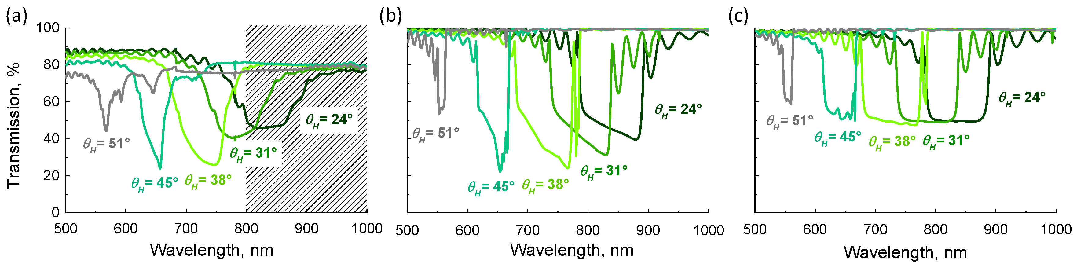
The experimentally measured and simulated transmission spectra for incident plane waves with TE polarization (along the z-axis) are compared in Figure 2 for five AOIs in glass. The incidence is defined by the angle with the helical axis, according to the convention of Figure 1a. The left Figure 2a shows the experimentally obtained spectra. The shaded area marks the range in which the characteristics of the polarizers are not optimal.
The incident light suffers from partial reflections at the glass/air interface and there is some scattering loss. As a result, the experimentally measured transmission remains below 90%. Note that, in order to experimentally obtain a given AOI in glass, the AOI in air has to be adapted, according to Snell’s law of refraction. The AOI in air with respect to the surface normal, for the five spectra is 0°, 11°, 21°, 33°, and 44°.
Figure 2b shows simulated transmission spectra according to the director distribution defined by Equation (4), thus corresponding to an unperturbed helix with an inclined helical axis. Figure 2c on the other hand shows simulated transmission spectra according to the director defined by Equation (6), with the director remaining parallel to the substrates.
For the three sets of spectra, we can see a similar blue shift and a similar narrowing of the band gap when the AOI is increased. However, there is a striking difference between the simulations for the inclined helix (Figure 2b) and the simulations for helix with planar director (Figure 2c). For the inclined helix, the transmission decreases well below 50% for wavelengths close to the long wavelength edge of the band gap, for below 51°. For the helix with planar director, the transmission stays ≈50% for all of the AOIs.
Figure 3, Figure 4 and Figure 5 show the spectral transmission for six different polarizations and five different angles of incidence , as obtained from measurements (a) and numerical simulations for CLC grating with inclined helix (b) and for a standard planar CLC layer, with director independent of the x-coordinate (c). In all of the graphs, the angle of incidence is expressed with respect to the helical axis (). In order to do that, for measurements and simulations of CLC grating with inclined helical axis, AOI is adjusted by adding the inclination angle to the angles of incidence used in the measurements (a) and simulations of CLC grating (b). In case of planar CLC layer = (c). This is only correct in a first approximation, since the refractive indices of the LC and of the glass substrate are different. There is some refraction at the boundaries and the relative angle between the k-vector and the helical axis is slightly different from the case of the inclined helix. This effect is not taken into account. The aim of planar CLC layer simulation is to investigate the role of the relative angle between the helical axis and propagation vector of the light.
For the measurements presented in Figure 3, Figure 4 and Figure 5a, the same remarks apply as in Figure 2a. In the shaded area the polarizer and the broadband quarter waveplate are not within the specifications. The values are not corrected for reflections at the glass/air interfaces and, therefore, remain below 90%. The angles of incidence reported on the graph refer to the angles in glass.
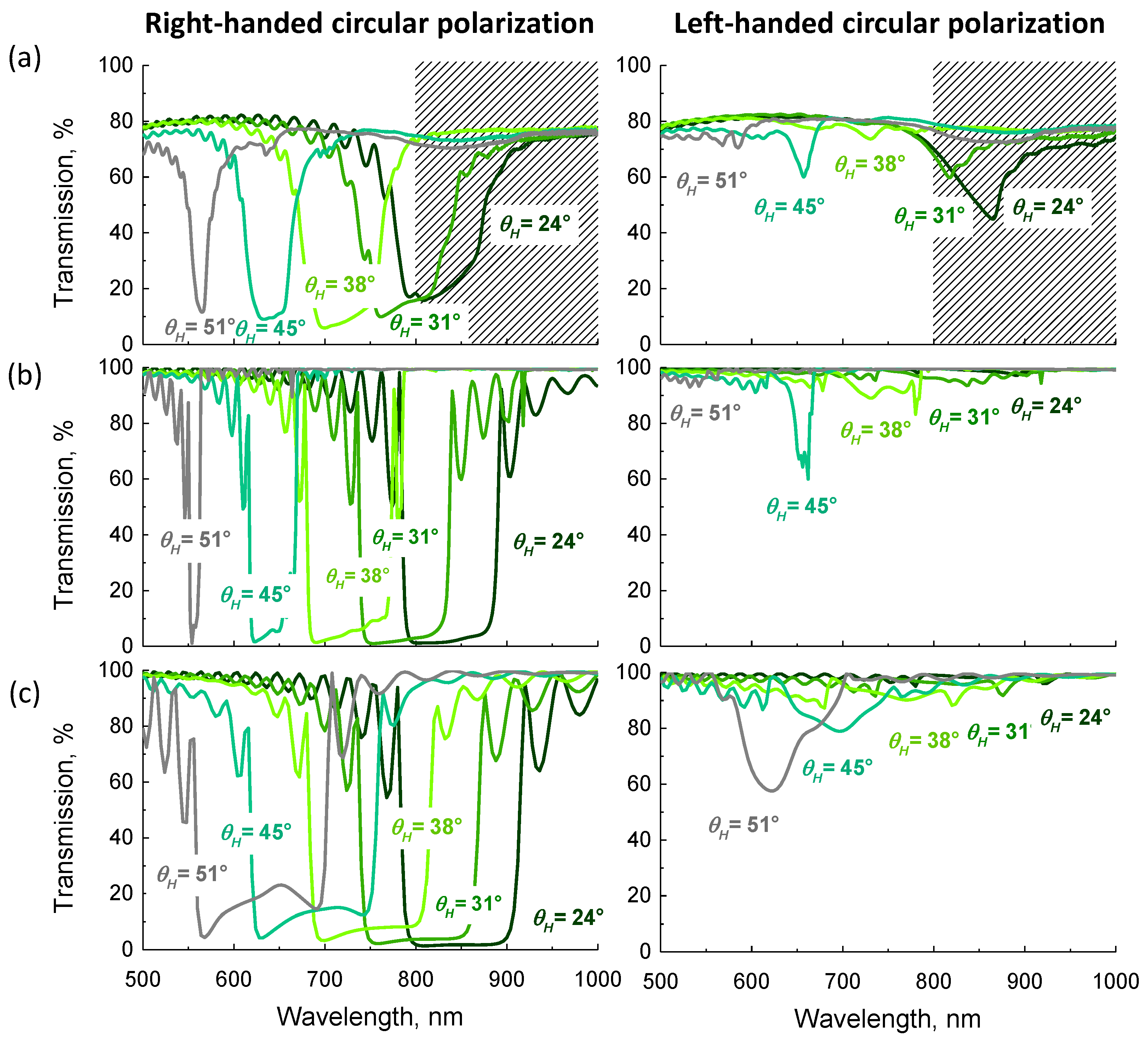
Figure 3 shows the transmission in the three cases for circularly polarized light. As expected, for right-handed circularly polarized (RHCP) light, the transmission is close to 0% in the reflection band region for all AOIs . For left-handed circularly polarized (LHCP) light, the transmission is close to 100%. Both experimentally and in the simulation for a CLC grating with inclined helix, a clear dip in transmission spectrum appears for LHCP at = 45°, which corresponds to = 21°. In case of the planar structure, the LHCP transmission keeps decreasing as AOI increases further.
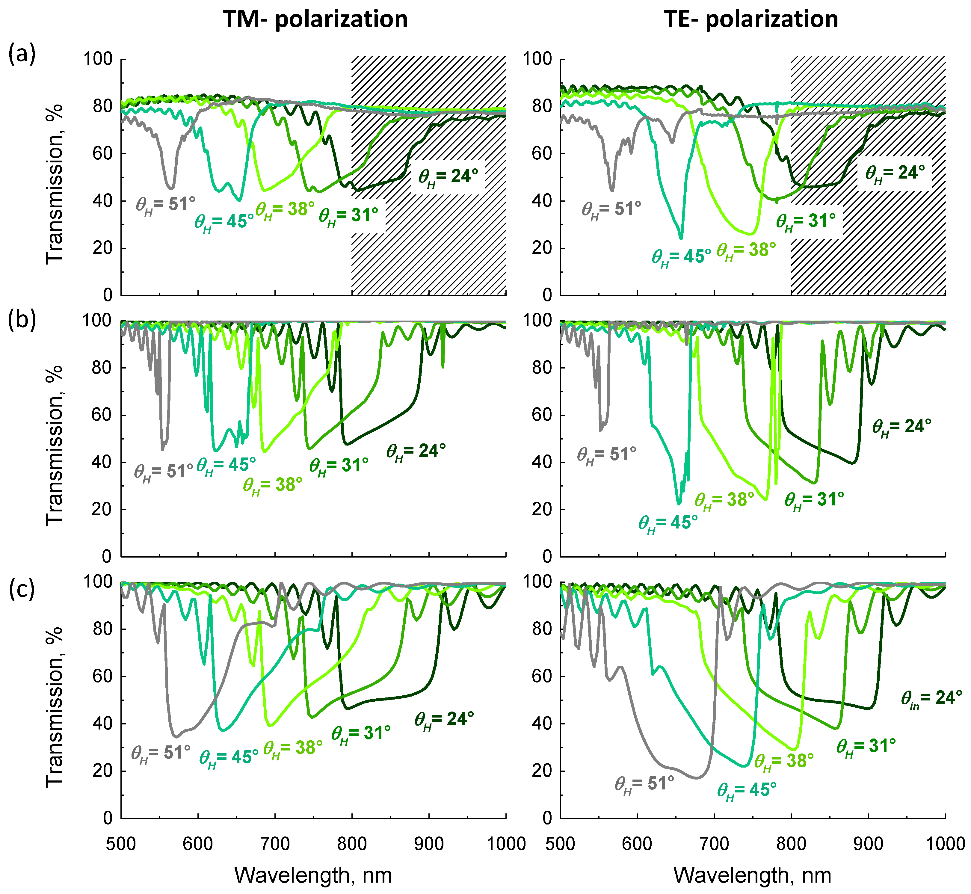
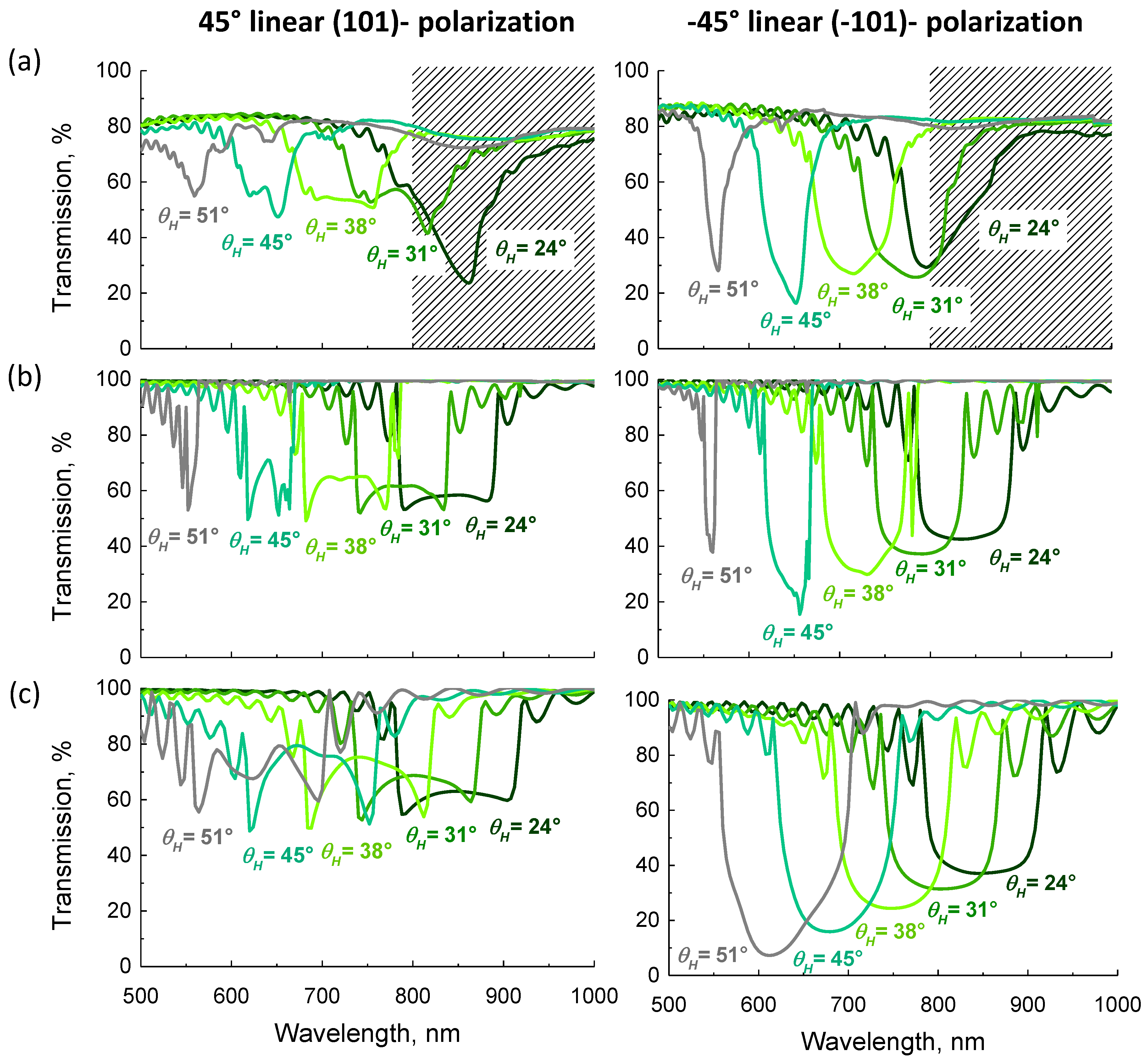
Apart from the circular polarizations, we also investigated the transmission for four different linear polarizations: TM (1 0 0), TE (0 0 1), +45° (1 0 1), and −45° (−1 0 1). In Figure 4, the transmission for incident TM and TE polarizations are compared. The general tendency is that the transmission in the band gap is wavelength dependent: for TM polarization, the transmission in the band gap increases with wavelength, while it decreases for TE polarization. Close to the long wavelength band edge, the transmission for TE is much lower than for TM polarization. For a linear polarization at +45° the transmission is lower near the two band edges, while, for −45°, the transmission is lower near the center of the band gap. This incident polarization dependency of the shape of the reflection band was already observed in the literature for a planar CLC layer [20].
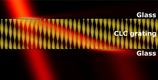
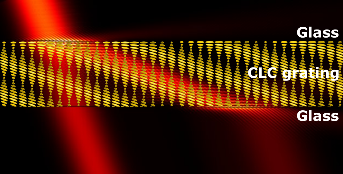
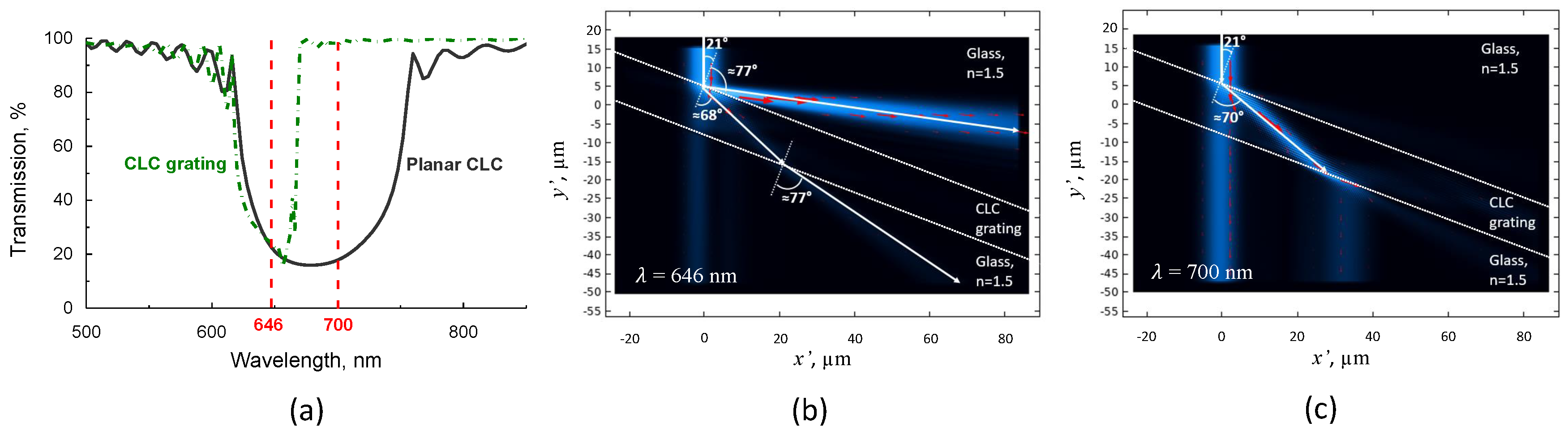
Apart from the transmission simulations for incident plane waves, we also simulated the distribution of the electric field intensity with a Gaussian beam with () and a fixed wavelength. The graph in Figure 6a shows the simulated transmission curves for −45° polarization. For nm both the CLC grating with inclined helix and the planar CLC have low transmission (Figure 6a). The field intensity distribution represented in Figure 6b for this case shows indeed that most of the light is reflected. For nm the transmission for the CLC grating with inclined helix is almost equal to 100% as can be seen in Figure 6a. For the same wavelength, the transmission for the planar CLC is still very low, because the wavelength is within the band gap. Figure 6c indicates that part of the light goes straight through, while the other part is first diffracted into the CLC layer at a large AOI, then travels inside the layer and at the other side is diffracted again into the vertical direction, being shifted by a distance of about 30 .
4. Discussion
First, we investigate the difference between the two configurations (inclined helix and vertical helix) that have been discussed in literature. Comparison with the experimental spectra in Figure 2a shows a very good agreement with Figure 2b, and not with Figure 2c. This indicates that the director distribution in our devices, consisting of a periodic grating at the interfaces filled with CLC, matches very well with the model of the inclined helix, described by Equation (4). This also indicates that the theoretical model (based on spherical trigonometry), neglecting the parallel CLC layer formed at the interface, is sufficiently accurate to describe the experimental structure. Therefore, in all of the simulations for CLC gratings we focused on the inclined helix model and no longer considered the standing helix gratings. For the simulation that was based on the vertical helix, the band edge wavelengths correspond to the experiment, but the spectral distribution is very different, in particular for larger angles of incidence.
When analyzing the transmission spectra in the Figure 3, Figure 4 and Figure 5, we can observe that there is a good agreement between the cases (a) and (b) for all polarizations and all angles . The band gap (best observed for right-handed circularly polarized (RHCP) light) shifts to the blue for larger angles of incidence. For wavelengths above 800 nm the correspondence is less good, as could be expected from limitations in the experimental setup mentioned before. In the experiments, the transmission remains above 10%, which may be due to imperfections in the layers (loss of polarization). The link between the simulations (b) and (c) is also clear, indicating that the relative angle between light propagation and helical axis is important. However, there are also several important differences, induced by the presence of a grating structure. The most striking difference is that the reflection band is much smaller for the inclined helix structure than for the planar CLC for the same (the short band-edge is at the same position, but the long band-edge occurs at a shorter wavelength). This is particularly true for the larger angles of incidence (e.g., for RHCP with the long band-edge is at nm for the CLC grating and at nm for the planar CLC). For the planar CLC layer the bandgap is becoming wider for larger AOI, as described in the literature [11,12,13]. However, for the CLC grating with inclined helix, the bandgap is becoming narrower with increasing AOI. Another difference is that the side lobes of the reflection band are further apart from each other for the planar CLC.
The position of side lobes of the reflection band in Figure 3, Figure 4 and Figure 5, corresponds very well between the measurement (a) and simulations (b). However, in the measured spectra, these side lobes are less strong than in the simulations, which could be related to the resolution of the spectro-photometer or small imperfections in the CLC structure, especially at the edges of the device, where photo-alignment is not strong enough. The oscillation of these side lobes, as explained in [20], gets faster at shorter wavelengths, since the normalized spacing () between two maxima is a constant for fixed cell thickness and AOI. According to this work, the spacing between maxima also increases with larger AOI. This explains why, in the case of an unpatterned planar CLC (c) we have slower oscillations than in the measured (a) and the simulated CLC grating with inclined helix (b), as the AOI (with respect to the substrate normal) in the case of planar CLC is larger than for the CLC grating, for the same angle .
It is well known that the transmission spectrum of a planar CLC for linearly polarized light strongly depends on the orientation of the polarization [21]. This is indeed observed in the simulations of Figure 4c and even more in Figure 5c. Additionally, the measured and simulated transmission spectra for a CLC grating with inclined helix strongly depend on the orientation of linearly polarized light. If the transmission spectra for two orthogonal polarizations are averaged out (RHCP and LHCP, TM, and TE, or +45° and −45°), the same spectrum, corresponding to the transmission for unpolarized light, is obtained.
The transmission spectra for LHCP light incident on a CLC grating with inclined helix (Figure 3) reveal that a reflection band for LHCP (in addition to the band for RHCP light) appears at (). This is in agreement with the angle that was obtained in the literature, at which the full reflection band appears in unpatterned planar CLC layers [17].
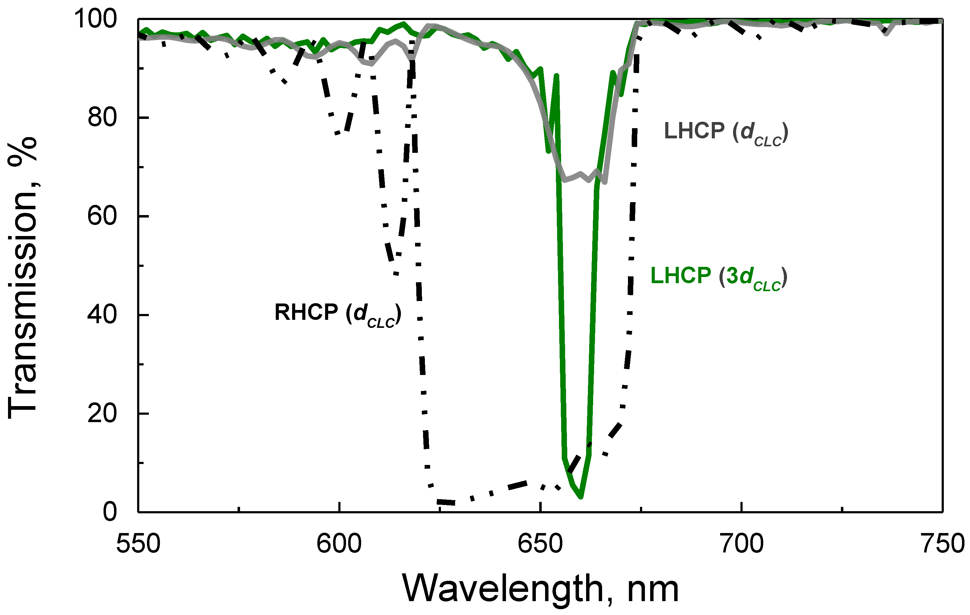
Even though we see stronger reflection for LHCP at , the reflection band for this polarization is not fully developed, because the layer is too thin [20,22]. That is because this mode (which is a Bloch mode in the periodic structure of the CLC) is evanescent with a small imaginary part and, therefore, a thick layer is required for full reflection. To check this, we carried out simulations for LHCP light for a CLC grating with inclined helix with a three times larger thickness. The results of the simulations, as presented in Figure 7, confirm that, for the larger thickness, the transmission drops to ≈0%.
In literature, it is shown that the reflection band for LHCP for planar CLC typically appears more or less in the middle of the selective reflection band [20]. Here, we find that, for the CLC grating with an inclined helix, the reflection band for LHCP light appears closer to the long wavelength edge of the (narrower) selective reflection band for RHCP light (Figure 3). We consider simulations with Gaussian beam in order to understand the origin of the narrowing of the selective reflection band for the CLC grating with inclined helix. From Figure 6b we find that the angle with the normal for the first diffraction order (reflected or transmitted) into air, , is found from the grating equation with :
with the angle of incidence with respect to surface normal and = 1.5 the refractive index of the glass substrate.
This allows for understanding why, for the CLC grating with inclined helix, the transmission increases from a low value to almost 100%, while, for the planar CLC, the transmission remains low over a much wider reflection band. The cut-off wavelength for reflection in the CLC grating corresponds to the wavelength at which the first diffraction order, according to the grating equation, is subjected to total internal reflection in the CLC layer. From the grating equation (Equation (7)), we find:
The cut-off wavelength for in our case is, for example, given by:
From the experimental and numerical data, we can indeed observe that, for (), the transmission increases to a high level near nm. This explains why, in a CLC grating with an inclined helix, the reflection band for LHCP is situated closer to the long wavelength edge of the selective reflection, as light with larger wavelengths is transmitted due to the limitation imposed by the grating equation. In the conventional planar CLC, the angle of the reflected light is equal to and there is no restriction related to diffraction, giving rise to a broader selective reflection band. In fact, for a CLC grating with an inclined helix, the LHCP reflection band completely disappears for larger AOIs, because of the limitation imposed by the grating equation.
The angle of propagation in the CLC grating with an inclined helix at the cut-off wavelength can be estimated from the critical angle for total internal reflection between the CLC and glass interface. From the simulations, we observe the propagation angle of 68° at 674 nm, which corresponds to the critical angle for total internal reflection between glass () and CLC with average refractive index . In a CLC grating with an inclined helix, light with wavelength 700 nm (above the cut-off value) is efficiently coupled into the CLC layer at an angle with the normal to the substrate of ≈70°, as can be seen in Figure 6c. Taking into account that the inclination axis of the helical axis is , the propagation is practically perpendicular to the helical axis of the CLC.
This is the first demonstration of efficient large-angle forward diffraction based on CLC with an inclined helical axis. Circularly polarized light is coupled into the CLC layer. When considering the ray propagation in the COMSOL simulation, it appears as if refraction occurs in the opposite direction than expected from the contrast in refractive index: although both refractive indices of the LC (1.54 and 1.74) are higher than that of the substrate (1.50), the light in the CLC makes a larger angle () with the normal than the light in the substrate (). This effect is entirely due to the periodicity of the structure near the surface of the layer.
The optical behavior of a CLC grating with an inclined helix can be understood by considering three layers: two linear gratings (one near the top substrate and one near the bottom substrate) that are responsible for diffraction, and a homogeneous CLC layer in which only certain Bloch modes can propagate. We show here that very high diffraction efficiency is not only observed when light is reflected, but it can also take place when light is propagating in the CLC itself, leading to a lateral displacement of the beam. We are the first to demonstrate this efficient lateral shift of light in a CLC layer with inclined helix, according to our knowledge.
The excellent agreement with experimental transmission spectra shows that the inclined helix model accurately describes the behavior of reflective CLC gratings, in contrast to the previously suggested vertical helix model [14,15]. Even though a similar configuration was suggested by [10], here we provide a complete description of the LC director orientation in the CLC grating with inclined helix. We also investigate the spectral response of CLC grating with inclined helix at large AOIs and observe the appearance of the reflection band for LHCP light.
5. Conclusions
The very good agreement between experimental and simulated transmission spectra results clearly indicates that, when CLC is deposited on a periodic surface alignment grating, an unperturbed CLC in the bulk is formed with an inclined helical axis. The inclination angle is determined by the periodicity of the grating and the pitch of the CLC. The inclination and azimuth angle of the director in the bulk of the CLC are accurately described by analytical formulae while using spherical trigonometry. For a number of features in the transmission spectra, it is sufficient to consider the relative angle between the propagation direction of the light and the helical axis of the CLC. As a result, the full reflection band for which reflection of circularly polarized light with opposite handedness takes place, occurs at a much smaller angle of incidence with respect to the layer normal. There is also a new phenomenon occurring in the CLC grating with inclined helical axis. The grating near the surface diffracts the light effectively into the first order, and the angle of reflection is determined by the AOI and period through the grating equation. The simulations show that there is a cut-off wavelength above which the first order diffraction can not be reflected into the substrate due to total internal reflection. We show that, for wavelengths above the cut-off wavelength, light is efficiently forward diffracted into the CLC layer and is transmitted at the other side of the layer. The optical components described here with their excellent diffraction efficiencies and operation under very large angles of incidence, may find applications in various optical components, such as lenses with high numerical apertures, waveguide couplers, and diffraction gratings for augmented reality. The thorough investigation in this paper should help to reach the full potential of these CLC based flat optical components.
Author Contributions
Conceptualization, M.S., I.N. and K.N.; methodology, M.S., I.N. and K.N.; software, M.S. and Y.Y.U.; validation, M.S., I.N., Y.Y.U., J.B. and K.N.; formal analysis, M.S.; investigation, M.S.; resources, M.S.; data curation, M.S.; writing–original draft preparation, M.S., I.N. and K.N.; writing–review and editing, M.S., I.N., Y.Y.U., J.B. and K.N.; visualization, M.S.; supervision, I.N., J.B. and K.N.; project administration, K.N.; funding acquisition, M.S., J.B. and K.N. All authors have read and agreed to the published version of the manuscript.
Funding
This work was funded by the Research Foundation—Flanders, grant number 1S88220N.
Conflicts of Interest
The authors declare no conflict of interest. The funders had no role in the design of the study; in the collection, analyses, or interpretation of data; in the writing of the manuscript, or in the decision to publish the results.
References
- Kress, B.; Starner, T. A review of head-mounted displays (HMD) technologies and applications for consumer electronics. In Photonic Applications for Aerospace, Commercial, and Harsh Environments IV. International Society for Optics and Photonics; Kazemi, A.A., Kress, B.C., Thibault, S., Eds.; SPIE: Philadelphia, PA, USA, 2013; Volume 8720, pp. 62–74. [Google Scholar]
- Guo, J.; Tu, Y.; Yang, L.; Wang, L.; Wang, B. Holographic waveguide display with a combined-grating in-coupler. Appl. Opt. 2016, 55, 9293–9298. [Google Scholar] [CrossRef] [PubMed]
- Pan, C.; Liu, Z.; Pang, Y.; Zheng, X.; Cai, H.; Zhang, Y.; Huang, Z. Design of a high-performance in-coupling grating using differential evolution algorithm for waveguide display. Opt. Express 2018, 26, 26646–26662. [Google Scholar] [CrossRef] [PubMed]
- Chen, W.T.; Zhu, A.Y.; Sanjeev, V.; Khorasaninejad, M.; Shi, Z.; Lee, E.; Capasso, F. A broadband achromatic metalens for focusing and imaging in the visible. Nat. Nanotechnol. 2018, 13, 220–226. [Google Scholar] [CrossRef] [PubMed] [Green Version]
- Kobashi, J.; Yoshida, H.; Ozaki, M. Planar optics with patterned chiral liquid crystals. Nat. Photonics 2016, 10, 389–392. [Google Scholar] [CrossRef]
- Yin, K.; Zhan, T.; Xiong, J.; He, Z.; Wu, S.T. Polarization Volume Gratings for Near-Eye Displays and Novel Photonic Devices. Crystals 2020, 10, 561. [Google Scholar] [CrossRef]
- Lee, Y.H.; Yin, K.; Wu, S.T. Reflective polarization volume gratings for high efficiency waveguide-coupling augmented reality displays. Opt. Express 2017, 25, 27008–27014. [Google Scholar] [CrossRef] [PubMed]
- Weng, Y.; Zhang, Y.; Cui, J.; Liu, A.; Shen, Z.; Li, X.; Wang, B. Liquid-crystal-based polarization volume grating applied for full-color waveguide displays. Opt. Lett. 2018, 43, 5773–5776. [Google Scholar] [CrossRef] [PubMed]
- Nys, I.; Stebryte, M.; Ussembayev, Y.Y.; Beeckman, J.; Neyts, K. Tilted Chiral Liquid Crystal Gratings for Efficient Large-Angle Diffraction. Adv. Opt. Mater. 2019, 7, 1901364. [Google Scholar] [CrossRef]
- Lee, Y.H.; He, Z.; Wu, S.T. Optical properties of reflective liquid crystal polarization volume gratings. J. Opt. Soc. Am. B 2019, 36, D9–D12. [Google Scholar] [CrossRef]
- Berreman, D.W.; Scheffer, T.J. Bragg Reflection of Light from Single-Domain Cholesteric Liquid-Crystal Films. Phys. Rev. Lett. 1970, 25, 577–581. [Google Scholar] [CrossRef]
- Ozaki, R. Simple model for estimating band edge wavelengths of selective reflection from cholesteric liquid crystals for oblique incidence. Phys. Rev. E 2019, 100, 012708. [Google Scholar] [CrossRef] [PubMed]
- Dreher, R.; Meier, G.; Saupe, A. Selective Reflection by Cholesteric Liquid Crystals. Mol. Cryst. Liq. Cryst. 1971, 13, 17–26. [Google Scholar] [CrossRef]
- Ozaki, R.; Hashimura, S.; Yudate, S.; Kadowaki, K.; Yoshida, H.; Ozaki, M. Optical properties of selective diffraction from Bragg-Berry cholesteric liquid crystal deflectors. OSA Continuum. 2019, 2, 3554–3563. [Google Scholar] [CrossRef]
- Cho, S.; Yoshida, H.; Ozaki, M. Emission Direction-Tunable Liquid Crystal Laser. Adv. Opt. Mater. 2020, 2000375. [Google Scholar] [CrossRef]
- Xiang, X.; Escuti, M.J. Numerical analysis of Bragg polarization gratings. J. Opt. Soc. Am. B 2019, 36, D1–D8. [Google Scholar] [CrossRef]
- Risse, A.M.; Schmidtke, J. Angular-Dependent Spontaneous Emission in Cholesteric Liquid-Crystal Films. J. Phys. Chem. C 2019, 123, 2428–2440. [Google Scholar] [CrossRef]
- Yaroshchuk, O.; Reznikov, Y. Photoalignment of liquid crystals: basics and current trends. J. Mater. Chem. 2012, 22, 286–300. [Google Scholar] [CrossRef]
- Berenger, J.P. A perfectly matched layer for the absorption of electromagnetic waves. J. Comput. Phys. 1994, 114, 185–200. [Google Scholar] [CrossRef]
- Takezoe, H.; Ouchi, Y.; Hara, M.; Fukuda, A.; Kuze, E. Experimental Studies on Reflection Spectra in Monodomain Cholesteric Liquid Crystal Cells: Total Reflection, Subsidiary Oscillation and Its Beat or Swell Structure. Jpn. J. Appl. Phys. 1983, 22, 1080–1091. [Google Scholar] [CrossRef]
- Belyakov, V. Optics of Chiral Liquid Crystals. In Diffraction Optics of Complex-Structured Periodic Media: Localized Optical Modes of Spiral Media; Springer International Publishing: Cham, Switzerland, 2019; pp. 41–95. [Google Scholar]
- Belyakov, V.A.; Semenov, S.V. Optical defect modes at an active defect layer in photonic liquid crystals. J. Exp. Theor. Phys. 2014, 118, 798–813. [Google Scholar] [CrossRef]
Figure 1.
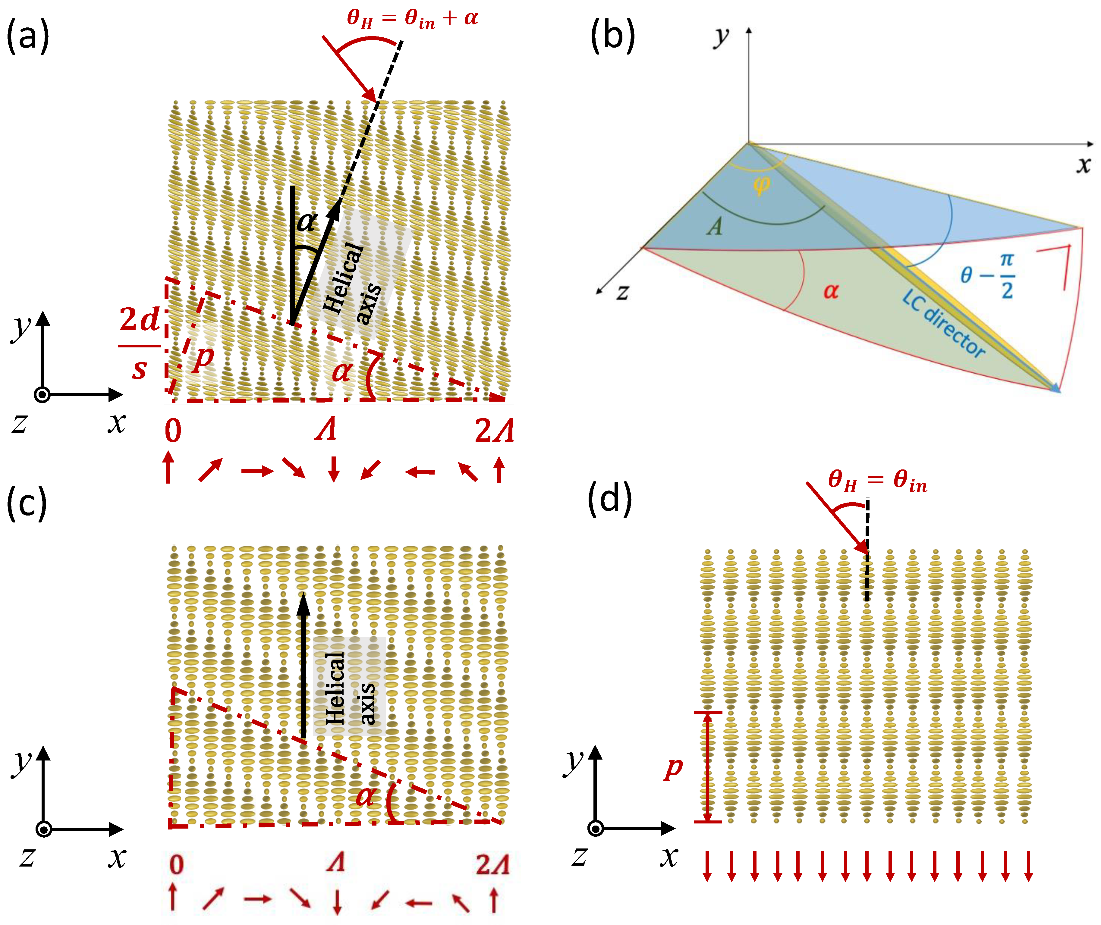
(a) Schematics of chiral liquid crystal (CLC) grating with inclined helix, here is the inclination angle of the helical axis, p is the helical pitch of the CLC, is the angle of incidence (AOI) with respect to surface normal, is the AOI with respect to the helical axis, d is the thickness of the CLC layer and s the number of half-pitches, red arrows indicate the pattern of photo-alignment at the surfaces; (b) schematics of LC director angle definition in spherical coordinate system. Here and are, respectively, the azimuthal and polar angle, A is the angle of LC director with respect to the z-axis; (c) schematics of CLC grating with vertical helix; (d) schematics of planar CLC layer. In the coordinate system used in this work x-z is the sample plane and y-axis is the substrate normal.
Figure 1.
(a) Schematics of chiral liquid crystal (CLC) grating with inclined helix, here is the inclination angle of the helical axis, p is the helical pitch of the CLC, is the angle of incidence (AOI) with respect to surface normal, is the AOI with respect to the helical axis, d is the thickness of the CLC layer and s the number of half-pitches, red arrows indicate the pattern of photo-alignment at the surfaces; (b) schematics of LC director angle definition in spherical coordinate system. Here and are, respectively, the azimuthal and polar angle, A is the angle of LC director with respect to the z-axis; (c) schematics of CLC grating with vertical helix; (d) schematics of planar CLC layer. In the coordinate system used in this work x-z is the sample plane and y-axis is the substrate normal.

Figure 2.
(a) Measured transmission spectra of CLC grating with = 700 nm for TE polarization for different angles with respect to the helical axis . Numerically calculated transmission spectra for TE polarization for different angles assuming inclined helix (b) and vertical helix (c) models.
Figure 2.
(a) Measured transmission spectra of CLC grating with = 700 nm for TE polarization for different angles with respect to the helical axis . Numerically calculated transmission spectra for TE polarization for different angles assuming inclined helix (b) and vertical helix (c) models.

Figure 3.
Transmission spectra for right- and left-handed circular polarization for different angles : (a) experimental; (b) simulated for CLC grating with inclined helix; and, (c) simulated for planar CLC layer.
Figure 3.
Transmission spectra for right- and left-handed circular polarization for different angles : (a) experimental; (b) simulated for CLC grating with inclined helix; and, (c) simulated for planar CLC layer.

Figure 4.
Transmission spectra for TM- and TE- polarization for different angles : (a) experimental; (b) simulated for CLC grating with inclined helix; and, (c) simulated for planar CLC layer.
Figure 4.
Transmission spectra for TM- and TE- polarization for different angles : (a) experimental; (b) simulated for CLC grating with inclined helix; and, (c) simulated for planar CLC layer.

Figure 5.
Transmission spectra for +45° (1 0 1) and −45° (−1 0 1) polarization for different angles : (a) experimental; (b) simulated for CLC grating with inclined helix; and, (c) simulated for planar CLC layer.
Figure 5.
Transmission spectra for +45° (1 0 1) and −45° (−1 0 1) polarization for different angles : (a) experimental; (b) simulated for CLC grating with inclined helix; and, (c) simulated for planar CLC layer.

Figure 6.
(a) Numerically calculated transmission spectra with linearly −45° (−1 0 1) polarized light at for a CLC grating with a 24° inclined helix (), and for a planar CLC with . Simulated field intensity distribution for a linearly −45° (−1 0 1) polarized Gaussian beam with wavelength (b) = 646 nm and (c) = 700 nm incident on the CLC grating at an angle ().

Figure 7.
Calculated transmission spectra for a CLC grating with inclined helix for (): for right-handed circularly polarized (RHCP) and left-handed circularly polarized (LHCP) on a grating with thickness , and for LHCP on a grating with thickness .
Figure 7.
Calculated transmission spectra for a CLC grating with inclined helix for (): for right-handed circularly polarized (RHCP) and left-handed circularly polarized (LHCP) on a grating with thickness , and for LHCP on a grating with thickness .

© 2020 by the authors. Licensee MDPI, Basel, Switzerland. This article is an open access article distributed under the terms and conditions of the Creative Commons Attribution (CC BY) license (http://creativecommons.org/licenses/by/4.0/).
Share and Cite
MDPI and ACS Style
Stebryte, M.; Nys, I.; Ussembayev, Y.Y.; Beeckman, J.; Neyts, K. Large Angle Forward Diffraction by Chiral Liquid Crystal Gratings with Inclined Helical Axis. Crystals 2020, 10, 807. https://0-doi-org.brum.beds.ac.uk/10.3390/cryst10090807
AMA Style
Stebryte M, Nys I, Ussembayev YY, Beeckman J, Neyts K. Large Angle Forward Diffraction by Chiral Liquid Crystal Gratings with Inclined Helical Axis. Crystals. 2020; 10(9):807. https://0-doi-org.brum.beds.ac.uk/10.3390/cryst10090807
Chicago/Turabian StyleStebryte, Migle, Inge Nys, Yera Ye. Ussembayev, Jeroen Beeckman, and Kristiaan Neyts. 2020. "Large Angle Forward Diffraction by Chiral Liquid Crystal Gratings with Inclined Helical Axis" Crystals 10, no. 9: 807. https://0-doi-org.brum.beds.ac.uk/10.3390/cryst10090807
Note that from the first issue of 2016, this journal uses article numbers instead of page numbers. See further details here.