Influence of Alumina Air-Abrasion on Flexural and Shear Bond Strengths of CAD/CAM Composite


1
Division of Biomaterials, Department of Oral Functions, Kyushu Dental University, Fukuoka 803-8580, Japan
2
Division of Operative Dentistry, College of Dentistry, Rangsit University, Pathum Thani 12000, Thailand
*
Author to whom correspondence should be addressed.
Crystals 2020, 10(10), 927; https://0-doi-org.brum.beds.ac.uk/10.3390/cryst10100927
Submission received: 1 September 2020
/
Revised: 7 October 2020
/
Accepted: 10 October 2020
/
Published: 12 October 2020
(This article belongs to the Special Issue Resin Ceramics Composite)
Abstract
:The purpose of this study was to clarify the influence of alumina air-abrasion on flexural and bond strengths of CAD/CAM composites. The flexural strength (FS) of two brands of commercial CAD/CAM composites was investigated by the three-point bending test using two specimen designs: the single-bar according to the ISO standard and the bonded-double-bar fabricated by bonding two bars with a resin cement. The bond strength between the composites and the resin cement was measured by a conventional shear bond strength (SBS) test. The FS of single-bar specimens was significantly decreased by the air-abrasion. For the FS of the bonded-double-bar specimen, on the other hand, there was no significant difference between the specimens with/without air-abrasion. The SBS for the composites was significantly increased by air-abrasion. The results suggest that alumina air-abrasion improves the SBS of the composites while weakening its FS. Contrarily, the FS of the air-abraded composite did not decrease when the composites were bonded with the resin cement.
1. Introduction
Computer-aided design/computer-aided manufacturing (CAD/CAM) is gaining more popularity amongst dental fields around the world. Unlike in the past, now the precision of the CAD/CAM system is comparable to other fabrication techniques [1,2,3,4]. The materials used for the CAD/CAM system have also developed, there are varieties of material to choose from. Recently, tooth-colored esthetic materials used for the CAD/CAM system were categorized into two types including ceramic and resin composite (thereafter composite) [5,6,7]. Since the first introduction of CAD/CAM composites in the market, Paradigm MZ100 (3M ESPE) in 2010, the materials have been improved so far in every aspect including their mechanical properties [5,6,8,9]. Large amounts of filler content and highly converted resin matrix, compared to composites for direct restoration, are the major reasons for their improved properties. Some of the CAD/CAM composites have flexural strength reaching 300 MPa. Such excellent properties allow us to use the CAD/CAM composite for single crown restoration up to the molar region [9,10]. However, some critical issues have been pointed out on restoration using the CAD/CAM composite; fracture and debonding failures of the crown after delivery within a short time period [10,11,12,13]. Although many fundamental and clinical researches have been conducted to overcome these issues [14,15,16,17,18,19,20,21,22,23], it still remains an open research problem.
Regarding the protocol for surface pretreatment of the CAD/CAM composites for cementation, although there is still no definite conclusion, some researchers and manufacturers recommend an alumina air-abrasion followed by silane primer application to the bonded (fit) surface before cementation [24,25]. Nonetheless, there is an issue considering possible undesirable consequences following alumina air-abrasion. According to the study on damage caused by the alumina air-abrasion [26], the surface of some CAD/CAM composites exhibited microcracks or large cracks following alumina air-abrasion. Although the author did not further investigate the strength of the air-abraded CAD/CAM composites, such microcracks on the surface may lead to a fatal fracture of the composite crowns. It is still unclear whether the increase in bond strength is traded with the decrease in strength of the CAD/CAM composite itself or not.
The present study aimed to investigate the influence of the alumina air-abrasion both with and without the artificial aging process or thermocycling on the flexural strength and bond strength of the CAD/CAM composite using two brands of commercially available ones. The flexural strength was examined by means of the three-point bending (TPB) test using two specimen designs: the single- bar shaped specimen with dimension in accordance with ISO standard, and the bonded-double-bar shaped specimen in which two half-thickness single bars are bonded to each other with a resin cement. The former specimen was examined to clarify the influence of the alumina air-abrasion on the flexural strength (FS) of the composites. The latter specimen was used to determine the effect of bonding with the resin cement on flexural strength of the abraded composites. The effect of the air- abrasion on the bond strength between the composites and the resin cement was examined by means of a conventional shear bond strength (SBS) test. Based on these TPB and SBS tests results, we discussed the effect of the air-abrasion both immediately and after thermocycling on the CAD/CAM composites.
2. Materials and Methods
Table 1 lists the materials used in the present study. Table 2 summarizes the experimental groups used in the TPB and SBS tests. Figure 1 describes specimen configurations for the TPB and SBS tests. Figure 2 depicts steps in the preparation of each type of specimen.
2.1. Preparation of Single-Bar Specimen for Three-Point Bending Test
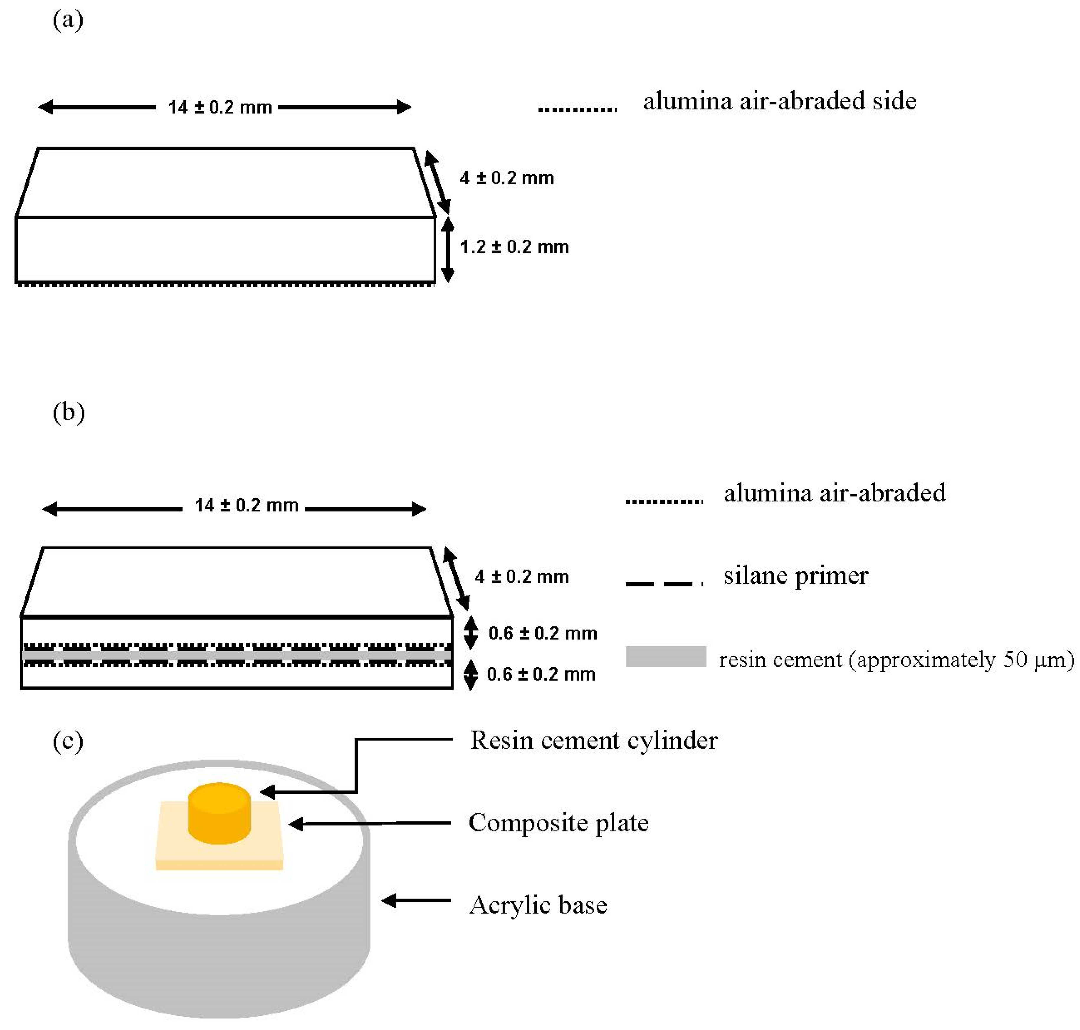
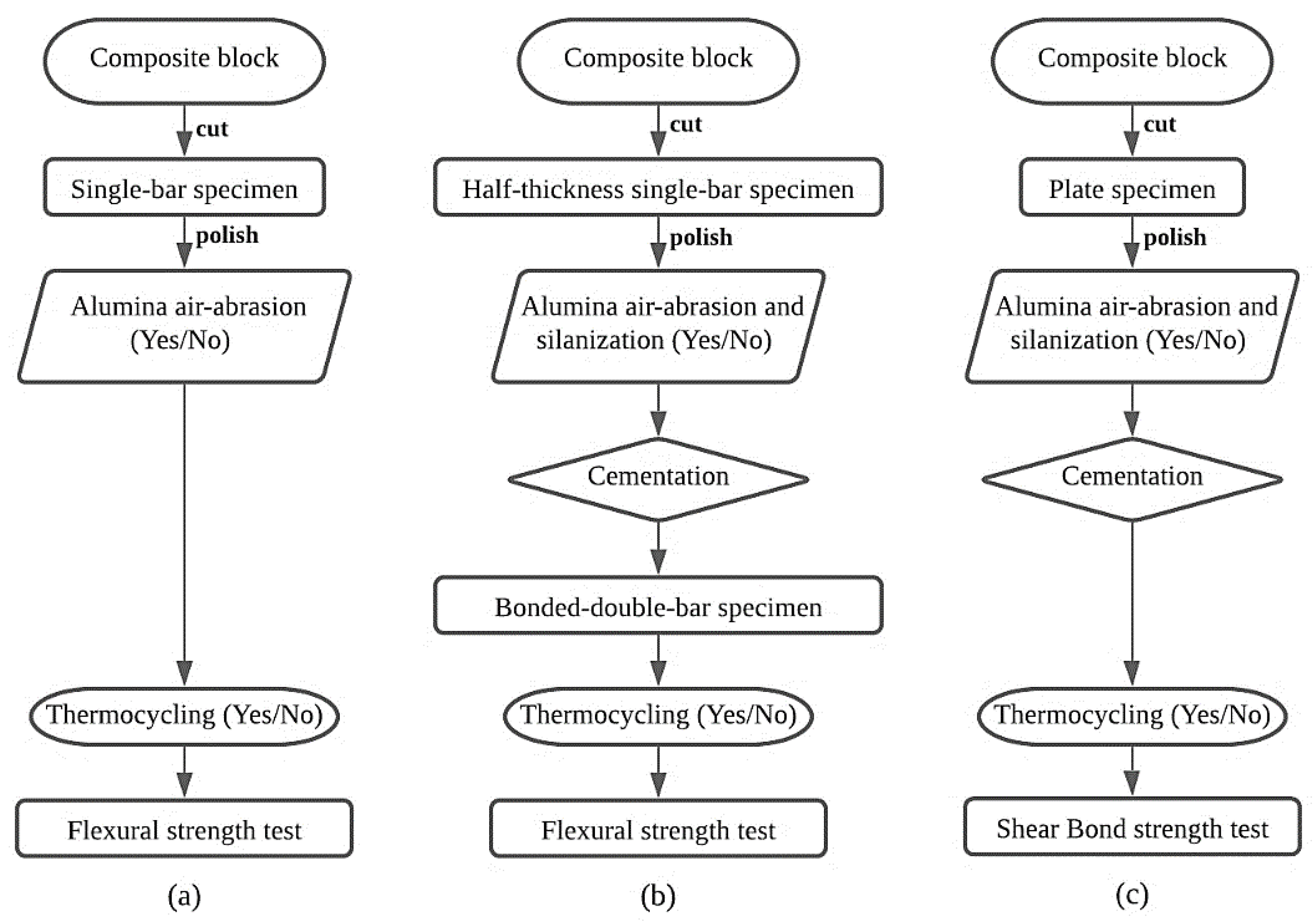
Figure 1a shows the single-bar specimen for the TPB test. Figure 2a depicts steps in the preparation of a single-bar specimen. This specimen dimension is in accordance with the standard protocol for ISO 6872:2008. Each CAD/CAM composite block was cut into bar-shaped specimens (n = 48) using a low-speed diamond wheel-saw (Model 650, South Bay Technology, CA, USA). Every specimen was ground and polished with up to #2000 silicon carbide papers to get a final dimension of 4.0 ± 0.2 × 14.0 ± 0.2 × 1.2 ± 0.2 mm and the dimension was confirmed by a digital vernier caliper (Mitutoyo CD-15CPX, Mitutoyo Corp., Kawasaki, Japan). The right angles between each face of the specimen were estimated by eye. Then, in order to reduce the edge failure during the TPB test, a chamfered edge of approximately 0.1 to 0.2 mm width was prepared using silicon carbide paper. The specimens were then divided in halves. One half was subjected to alumina air-abrasion on only one side, the flat surface, using an airborne-particle abrasion machine (Adabrader, Morita, Tokyo, Japan) at 0.2 MPa pressure for 10 s, from a distance of 10 mm perpendicularly. The other half was a control group with no air-abrasion. Then, every specimen was stored in a water bath at 37 °C for 1 day. Thereafter, each group of specimens was divided into two subgroups for thermocycling which was conducted by alternatively immersing in two water baths between 5 °C and 55 °C for 20,000 cycles with a 60 s dwell time for each temperature.
2.2. Preparation of Bonded-Double-Bar Specimen for Three-Point Bending Test
Figure 1b denotes the bonded-double-bar specimen for the TPB test. Figure 2b depicts steps in the preparation of a bonded-double-bar specimen. Bar-shaped specimens were prepared in the same way as for the single-bar specimens, except for the thickness. In this case, the final dimension of the cut and polished specimens before bonding was 4.0 ± 0.2 × 14.0 ± 0.2 × 0.6 ± 0.1 mm. One-side surface on the single-bar specimens was subjected to the alumina air-abrasion followed by silanization using a silane primer (Porcelain primer). The specimens in the same group were paired and cemented. A generous amount of the resin cement (ResiCem) was applied on the air-abraded side of the specimen. Next, the other prepared bar sample was placed on the cement, surface-treated side facing the cement. A 100 g load was placed on the specimen for 1 min to standardize cement thickness. These procedures were confirmed in the preliminary experiment which was carried out prior to the current experiment. Weight and time were adjusted to find out the best way to achieve a constant cement thickness of approximate 50 µm, which was confirmed by an optical microscope. Preliminary light activation was performed with a hand-held light activator (Pencure, J. Morita, Tokyo, Japan). After that, the cement of the specimen was completely polymerized using a laboratory light curing unit (α Light II N, J. Morita, Tokyo, Japan) for 5 min per side. After cleaning-off the excess cement, the specimen was edge-chamfered in the same way as in the single-bar specimen. The resultant bonded-double-bar specimens were stored in 37 °C water for 1 day, and were divided in half, one group to receive thermocycling, while the other not.
2.3. Preparation of Specimen for Shear Bond Strength Test
The bond strength between each composite and the resin cement was measured using the SBS test with the specimen as illustrated in Figure 1c according to the previous study [27]. Figure 2c depicts steps in the preparation of a shear-bond-strength specimen. Each composite block was cut into 1 mm thick plates (n = 48) and polished in the same way as the specimen for the TPB test. The polished plate was then embedded in an acrylic ring using self-cured resin. Half of the specimens were subjected to the alumina air-abrasion followed by silanization using the silane primer, while the others were not. A Teflon tube, with an internal diameter of 5 mm, was positioned on the sample surface using a fixed tape, to standardize the bonding area. The resin cement was loaded on the surface through the Teflon tube to form a 3 mm high rod. Cement polymerization was carried out in the same way as for the bonded-double-bar specimen. The resultant samples were then stored in 37 °C water for 1 day, and were divided in half, one group to receive the thermocycling, while the other not.
2.4. Three-Point Bending Test
The TPB test was carried out with a jig (supporting span: 12 mm) and a crosshead according to ISO6872:2008 using a universal testing machine (AG-X, Shimadzu Corp., Kyoto, Japan) with a speed of 1 mm/min. For the single-bar specimen, the air-abraded-side was positioned down. For the bonded-double-bar specimens, there was no protocol for positioning the specimens. The flexural strength (σ) was calculated using the following equation:
where F is the maximum load, L is the supporting span, b is the width of the specimen, and h is the thickness of the specimen.
σ = 3FL/2bh2
2.5. Shear Bond Strength Test
The SBS was measured using the universal testing machine. The specimen was fixed with a specialized jig [27] which helped positioning the sample in such a way that the composite–resin cement interface was parallel exactly at the loading blade which moved at 1 mm/min. The maximum load was recorded when the resin cement cylinder detached from the composite surface. The SBS was calculated by dividing the maximum load by the bonding area. After the SBS test, the detached surface of the composites was observed by the naked eye and an optical microscope to classify five categories of failure mode; AD: adhesive failure, CO-Com: cohesive failure in composite, CO-Cem: cohesive failure in cement, AD-Com: mixed failure adhesive + cohesive in composite, and AD-Cem: mixed failure adhesive + cohesive in cement.
2.6. Statistical Analysis
Statistical analysis of the FS and SBS data was performed with a statistical software EZR version 1.38 (Saitama Medical Center, Jichi Medical University, Saitama, Japan) using two-way analysis of variance (ANOVA) followed by Tukey’s test to find statistically significant difference between groups, whereby p < 0.05 was considered statistically significant.
3. Results
3.1. Flexural Strength of the Single-Bar Specimen
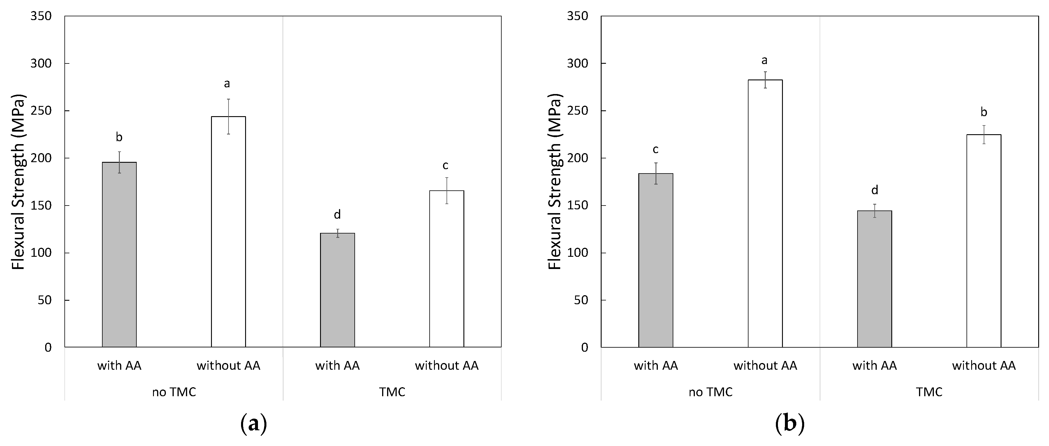
Two-way ANOVA revealed that the FS for single-bar specimens was significantly affected by the air-abrasion and thermocycling (p < 0.05) for both SH and CE composites. There was significant interaction between the air-abrasion and thermocycling for the CE composite (p < 0.05) but no significance for the SH composite (p = 0.6595). Figure 3 shows FS of the single-bar specimens for each composite with Tukey’s post-hoc test result. For the SH composite, FSs of the non-abraded specimens before and after the thermocycling were 243.8 ± 18.4 MPa and 165.7 ± 13.8 MPa respectively. When the specimens were air-abraded, the strength significantly decreased in comparison with those of the non-abraded specimens; 195.5 ± 11.2 MPa and 120.8 ± 4.4 MPa before and after the thermocycling respectively. The FS of the CE composite also gave results in the same trend. The FSs of the CE composite before and after the thermocycling were 282.5 ± 8.6 MPa and 183.8 ± 11.2 MPa respectively. When the specimens were air-abraded, the strength significantly decreased in comparison with those of the non-abraded specimens; 224.8 ± 9.7 MPa and 144.4 ± 7.0 MPa before and after the thermocycling respectively. Statistical analysis indicated significant difference (p < 0.05) in FSs between air-abraded and non-abraded specimens, also between before and after thermocycling, for both SH and CE composites. These results suggested that the alumina air-abrasion and the thermocycling both weakened the strengths of the composites.
3.2. Flexural Strength of Bonded-Double-Bar Specimen
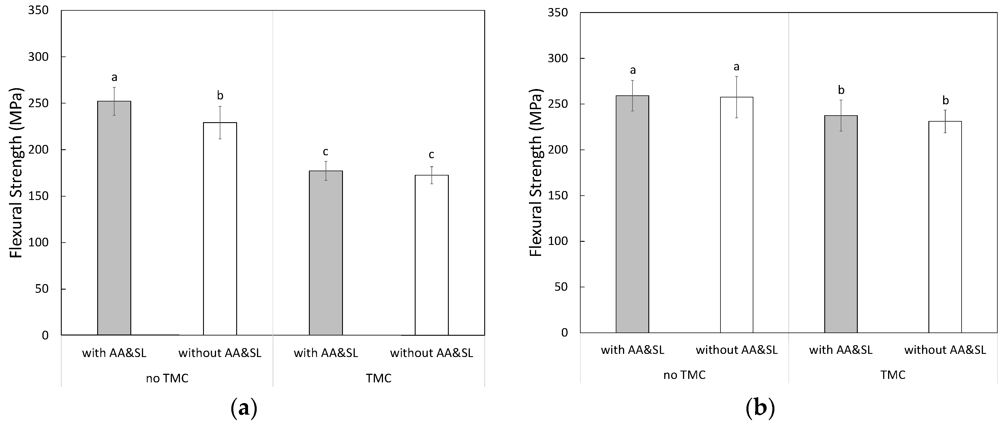
Two-way ANOVA revealed that FS of the bonded-double-bar specimen for the SH composites was significantly affected by the air-abrasion and thermocycling (p < 0.05). There was significant interaction between the air-abrasion and thermocycling for the SH composite (p < 0.05). Meanwhile, FS for the CE composite was significantly affected by thermocycling (p < 0.05) but not by air-abrasion (p = 0.6248). There was no significant interaction between air-abrasion and thermocycling (p = 0.6248). Figure 4 shows FS of the bonded-double-bar specimens for each composite with Tukey’s post-hoc test result. For the SH composite, FSs of the non-abraded specimens before and after the thermocycling were 229.3 ± 17.6 MPa and 172.6 ± 9.3 MPa, respectively. When the specimens received air-abrasion, the FSs were 252.2 ± 14.9 MPa and 177.3 ± 10.3 MPa before and after thermocycling respectively. For the CE composite, FSs of the air-abraded specimens were 257.7 ± 22.6 MPa and 231.1 ± 12.4 MPa before and after thermocycling, respectively. When the specimens received air-abrasion, the FSs were 259.2 ± 16.7 MPa and 237.6 ± 17.0 MPa before and after thermocycling, respectively. Unlike in the single-bar specimen, statistical analysis did not find significant difference (p > 0.05) in the FSs for both SH and CE composites between non-abraded and air-abraded specimens. For the SH composite before thermocycling, the FS of the air-abraded specimen was higher than that of the non-abraded specimen. However, after thermocycling, FSs between air-abraded and non-abraded specimens were statistically comparable (p = 0.8292 for SH, p = 0.800 for CE). Undoubtedly, the thermocycling caused significant decrease in FS for both SH and CE composites. These results indicated that the alumina air-abrasion did not reduce the FS of the bonded-double-bar specimens.
3.3. Shear Bond Strength
Two-way ANOVA revealed that the SBS for the SH composites was significantly affected by air-abrasion and thermocycling (p < 0.05). There was no significant interaction between the air-abrasion and thermocycling (p = 0.3525). Figure 5 gives SBS between each composite and the resin cement with Tukey’s post-hoc test result. For the SH composite before thermocycling, SBS of the air-abraded specimen (34.0 ± 5.0 MPa) was significantly higher (p < 0.05) than that of the non-abraded specimen (25.8 ± 4.2 MPa). Likewise, after thermocycling, SBS of the air-abraded specimen (10.0 ± 1.1 MPa) was significantly higher (p < 0.05) than that of the non-abraded specimen (3.6 ± 0.7 MPa). The CE composite also showed results in the same trend. SBSs of the air-abraded specimen before and after the thermocycling (41.4 ± 6.5 MPa, 12.6 ± 1.9 MPa respectively) were significantly higher (p < 0.05) than those of non-abraded specimen (30.9 ± 4.2 MPa, 8.1 ± 2.1 MPa respectively). Figure 6 denotes their percent values for each failure mode. The results of the failure modes indicated that 100% of adhesive failure was observed in every group of specimens except for the air-abraded specimen before thermocycling. These results indicated that the alumina air-abrasion could strengthen the bond strength between each composite and the resin cement.
4. Discussion
There are many publications evaluating FS of CAD/CAM composites, either with or without intervention. Lauvahutanon, et al. [9] reported a range of FS varying from 127 to 242 MPa in tested composites. When the composites were subjected to various kinds of artificial aging, most of the FSs dropped significantly. Some studies used thermocycling as an aging method and found a significant drop of FS for the tested composites [28,29,30], while Eglimez, et al. [31] exposed Lava Ultimate and GC Cerasmart to water storage, autoclave treatment, and thermocycling and reported a significant drop of FS. The present study also showed the same trend of results, both CE and SH composites had significant drops of FS after thermocycling (Figure 3). The regression in FS of composites mostly occurs by function of hydrolysis in the water-related aging procedure [31]. It is plausible that water penetrates into the resin matrix, softens the polymer network and also breaks the siloxane bond between the resin matrix and the silica fillers [32,33].
Prior to cementation of the CAD/CAM composites, the majority of the manufacturers recommend roughening the fit surface of the restoration by alumina air-abrasion at 0.2–0.3 MPa pressure for 10 s, from a distance of 10 mm (e.g., Shofu Block HC Hard Instruction). There are a number of publications studying alternative surface treatment protocols including alumina air-abrasion at 0.1 MPa [19]; air-abrasion with glass beads at 0.4 MPa [15]; air-abrasion with the CoJet™ system [21,23]; or etching with hydrofluoric acid (HF) [17]. From the ones of recent researches, the alumina air-abrasion and HF are still by far the most promising methods to create surface roughness [24,25]. Almost every research showed that these surface treatments increased bond strength by surface roughening. Nevertheless, surface roughening should be carried out with caution. According to a publication of Yoshihara, et al. [26], there were disadvantages of alumina air-abrasion. The authors evaluated the surface of various CAD/CAM composites with SEM observation before and after alumina air-abrasion and found that some composites exhibited surface and subsurface cracks. These cracks could possibly weaken the composite regarding the results from the current study.
In the present study, the results from the single-bar TPB test (Figure 3) revealed a significant reduction in the FS of both CE and SH composites. This result is in line with the studies by Sevcan, et al. in 2018 [34]. Xu, Garry, and Owen [35] explained that when the tested specimen had few surface flaws or defects at the tension side under stress loading area, the resulted FS would be higher compared to the specimen with many flaws or defects in the stated area. Consequently, when the specimen is air-abraded, especially on the tension side, the specimen is prone to break much easier at lower loading. As well, the decrease in FS of the composites might not fully represent the actual reduction in strength of the material.
Though the TPB test for the bonded-double-bar specimen (Figure 1b) is not listed in common standard testing methods of dental materials according to ISO standard, some researches in the engineering field adopted the present specimen configuration of the bonded-double-bar [36,37,38,39,40]. Because in real clinical situations, every material used in fabrication of fixed prostheses is used in supreme close contact with the cement, it is reasonable to include the cement layer into the specimen design and experiment. There have been many publications regarding FS when the restorative material was evaluated in association with the cement layer [35,41,42]. Plus, there was also a study utilizing a dentine analog to simulate a bonded-crown-on-tooth situation [43]. This study, instead, chose to use the material itself as a substrate to simulate that situation. The fact that the bonded-double-bar specimen included two thin bar samples together ensured that if the alumina air-abrasion weakening effect really could not be counteracted by proper bonding, the alumina abraded groups would demonstrate decreased flexural strength values.
From the results of FS for the bonded-double-bar specimen (Figure 4), unlike that of the single-bar specimens, the specimens which received alumina air-abrasion and silanization before cementation either had a comparable or a higher FS compared to the non-abraded specimens. This finding can partly be explained by the publication from Xu, Garry, and Owen [35]. They reported a significantly higher FS of a porcelain specimen when the specimen was coated with resin cement. They explained that the polymeric resin matrix in the resin cement helped to stabilize the innate flaws on the fit surface of the porcelain, and the stabilizing process was achieved by chemical bonding from silanization. Furthermore, Nathanson et al. [44] formerly presumed that the resin cement created a stress that held the material structure together. Marquis, et al. [45] believed in a crack healing mechanism, saying that interpenetration of the resin cement into the crack reduced the effective crack length and the resulting stress.
In order to gain a higher and more durable bond, it is well-accepted that increasing surface roughness in conjunction with chemical bond enhancement is a fundamentally important process. The bonded surface can be roughened by either mechanical means like alumina air-abrasion or chemical etching with HF. The roughening process will increase the surface area and also create micromechanical interlocking between the bonded surface and the resin cement. On the other hand, silane primer focuses on increasing bond strength via chemical bond promotion. The silane coupling agent in the primer reacts to silanol groups on the filler particles, resulting in an increment of bond strength between the composite and the resin cement [46]. The present study focuses on alumina air-abrasion followed by silanization as methods to achieve strong and durable bonds because it is one of the most well-approved and obtainable in the market. The SBS test revealed that the chosen method increased bond strength of the CAD/CAM composite to resin cement both immediately after cementation and after thermocycling. The results of the failure modes for the composites (Figure 6) supported the SBS test result. The results from the current study were of the same trend as previous researches [17,18,19,20,22,23].
In summary, we found that the alumina air-abrasion itself improves the bond strength of the CAD/CAM composites and weakens the flexural strength. In the case of the air-abraded composites with bonding to the resin cement via silanization, meanwhile, the flexural strength did not decrease. This finding indicates that alumina air-abrasion with silanization for bonding of the CAD/CAM composite to the resin cement can be recommended to reduce the risks of fracture and debonding failures in practical restorations.
5. Conclusions
The alumina air-abrasion to the CAD/CAM composites increased their shear bond strengths to the resin cement while decreasing the flexural strength of the single-bar specimen. On the other hand, the flexural strength was not reduced by alumina air-abrasion followed by silanization and bonding to the resin cement. To conclude, the alumina air-abrasion on CAD/CAM composite with appropriate cementation could improve bond strength without weakening its mechanical strength.
Author Contributions
P.K. designed and performed the experiment and wrote the manuscript in consultation with H.I. and Y.N. and H.S. supervised the research. All authors have read and agreed to the published version of the manuscript.
Funding
This research was supported by JSPA KAKENHI Grant Number JP 20K21685.
Conflicts of Interest
The authors declare no conflict of interest.
References
- Yang, X.; Lv, P.; Liu, Y.; Si, W.; Feng, H. Accuracy of digital impressions and fitness of single crowns based on digital impressions. Materials 2015, 8, 3945–3957. [Google Scholar] [CrossRef]
- Al-hawwaz, Z.M.; Ibraheem, A.F. Marginal and internal fitness of full contour CAD/CAM fabricated zirconia crowns using different digital intra-oral scanners (an in vitro study). JPAM 2018, 12, 839–844. [Google Scholar] [CrossRef]
- Amornvit, P.; Sanohkan, S.; Peampring, C. Studying the optical 3D accuracy of intraoral scans: An in vitro study. J. Healthc. Eng. 2020, 2020, 5739312. [Google Scholar] [CrossRef] [PubMed] [Green Version]
- El Ghoul, W.A.; Özcan, M.; Ounsi, H.; Tohme, H.; Salameh, Z. Effect of different CAD-CAM materials on the marginal and internal adaptation of endocrown restorations: An in vitro study. J. Prosthet. Dent. 2020, 123, 128–134. [Google Scholar] [CrossRef] [PubMed] [Green Version]
- Mainjot, A.K.; Dupont, N.M.; Oudkerk, J.C.; Dewael, T.Y.; Sadoun, M.J. From artisanal to CAD-CAM blocks: State of the art of indirect composites. J. Dent. Res. 2016, 95, 487–495. [Google Scholar] [CrossRef] [PubMed]
- Ruse, N.D.; Sadoun, M.J. Resin-composite blocks for dental CAD/CAM applications. J. Dent. Res. 2014, 93, 1232–1234. [Google Scholar] [CrossRef] [PubMed] [Green Version]
- Lambert, H.; Durand, J.C.; Jacquot, B.; Fages, M. Dental biomaterials for chairside CAD/CAM: State of the art. J. Adv. Prosthodont. 2017, 9, 486–495. [Google Scholar] [CrossRef] [PubMed] [Green Version]
- Giordano, R. Materials for chairside CAD/CAM-produced restorations. J. Am. Dent. Assoc. 2006, 137, 14S–21S. [Google Scholar] [CrossRef]
- Lauvahutanon, S.; Takahashi, H.; Shiozawa, M.; Iwasaki, N.; Asakawa, Y.; Oki, M.; Finger, W.J.; Arksornnukit, M. Mechanical properties of composite resin blocks for CAD/CAM. Dent. Mater. J. 2014, 33, 705–710. [Google Scholar] [CrossRef] [Green Version]
- Nihei, T.; Ohkubo, C.; Nishiyama, Y.; Tsubota, Y.; Koizumi, H.; Maseki, T.; Miyazaki, M. A report on the clinical use of bonding systems for coronal restorations produced from CAD/CAM resin blocks. Dent. Mater. J. 2020, in press. [Google Scholar] [CrossRef]
- Kelly, J.R. Computer-aided designed/computer-assisted manufactured (CAD/CAM) all-ceramic crowns appear to perform better than all-composite resin crowns following the first 3 years of placement. J. Evid. Based. Dent. Pract. 2011, 11, 203–205. [Google Scholar] [CrossRef] [PubMed]
- Miura, S.; Kasahara, S.; Yamauchi, S.; Katsuda, Y.; Harada, A.; Aida, J.; Egusa, H. A possible risk of CAD/CAM-produced composite resin premolar crowns on a removable partial denture abutment tooth: A 3-year retrospective cohort study. J. Prosthodont. Res. 2019, 63, 78–84. [Google Scholar] [CrossRef]
- Zimmermann, M.; Koller, C.; Reymus, M.; Mehl, A.; Hickel, R. Clinical evaluation of indirect particle-filled composite resin CAD/CAM partial crowns after 24 months. J. Prosthodont. 2018, 27, 694–699. [Google Scholar] [CrossRef] [Green Version]
- Stawarczyk, B.; Stich, N.; Eichberger, M.; Edelhoff, D.; Roos, M.; Gernet, W.; Keul, C. Long-term tensile bond strength of differently cemented nanocomposite CAD/CAM crowns on dentin abutment. Dent. Mater. 2014, 30, 334–342. [Google Scholar] [CrossRef]
- Arao, N.; Yoshida, K.; Sawase, T. Effects of air abrasion with alumina or glass beads on surface characteristics of CAD/CAM composite materials and the bond strength of resin cements. J. Appl. Oral Sci. 2015, 23, 629–636. [Google Scholar]
- Cekic-Nagas, I.; Ergun, G.; Egilmez, F.; Vallittu, P.K.; Lassila, L.V.J. Micro-shear bond strength of different resin cements to ceramic/glass-polymer CAD-CAM block materials. J. Prosthodont. Res. 2016, 60, 265–273. [Google Scholar] [CrossRef] [PubMed] [Green Version]
- Kömürcüoglu, M.B.; Sagirkaya, E.; Tulga, A. Influence of different surface treatments on bond strength of novel CAD/CAM restorative materials to resin cement. J. Adv. Prosthodont. 2017, 9, 439–446. [Google Scholar] [CrossRef] [PubMed] [Green Version]
- Higashi, M.; Matsumoto, M.; Kawaguchi, A.; Miura, J.; Minamino, T.; Kabetani, T.; Takeshige, F.; Mine, A.; Yatani, H. Bonding effectiveness of self-adhesive and conventional-type adhesive resin cements to CAD/CAM resin blocks. Part 1: Effects of sandblasting and silanization. Dent. Mater. J. 2016, 35, 21–28. [Google Scholar] [CrossRef] [PubMed] [Green Version]
- Naruse, Y.; Takagaki, T.; Matsui, N.; Sato, T.; Ali, A.; Ikeda, M.; Nikaido, T.; Tagami, J. Effect of alumina-blasting pressure on adhesion of CAD/CAM resin block to dentin. Dent. Mater. J. 2018, 37, 805–811. [Google Scholar] [CrossRef]
- Reymus, M.; Roos, M.; Eichberger, M.; Edelhoff, D.; Hickel, R.; Stawarczyk, B. Bonding to new CAD/CAM resin composites: Influence of air abrasion and conditioning agents as pretreatment strategy. Clin. Oral Investig. 2019, 23, 529–538. [Google Scholar] [CrossRef]
- Alp, G.; Subaşı, M.G.; Johnston, W.M.; Yilmaz, B. Effect of different resin cements and surface treatments on the shear bond strength of ceramic-glass polymer materials. J. Prosthet. Dent. 2018, 120, 454–461. [Google Scholar] [CrossRef] [PubMed]
- Emsermann, I.; Eggmann, F.; Weiger, R.; Krastl, G.; Amato, J. Influence of pretreatment methods on the adhesion of composite and polymer infiltrated ceramic CAD-CAM blocks. J. Adhes. Dent. 2019, 21, 433–443. [Google Scholar] [PubMed]
- Tekçe, N.; Tuncer, S.; Demirci, M.; Kara, D.; Baydemir, C. Microtensile bond strength of CAD/CAM resin blocks to dual-cure adhesive cement: The effect of different sandblasting procedures. J. Prosthodont. 2019, 28, e485–e490. [Google Scholar] [CrossRef] [PubMed]
- Mine, A.; Kabetani, T.; Kawaguchi-Uemura, A.; Higashi, M.; Tajiri, Y.; Hagino, R.; Imai, D.; Yumitate, M.; Ban, S.; Matsumoto, M.; et al. Effectiveness of current adhesive systems when bonding to CAD/CAM indirect resin materials: A review of 32 publications. Jpn. Dent. Sci. Rev. 2019, 55, 41–50. [Google Scholar] [CrossRef] [PubMed]
- Yu, H.; Özcan, M.; Yoshida, K.; Cheng, H.; Sawase, T. Bonding to industrial indirect composite blocks: A systematic review and meta-analysis. Dent. Mater. 2020, 36, 119–134. [Google Scholar] [CrossRef] [PubMed]
- Yoshihara, K.; Nagaoka, N.; Maruo, Y.; Nishigawa, G.; Irie, M.; Yoshida, Y.; Van Meerbeek, B. Sandblasting may damage the surface of composite CAD-CAM blocks. Dent. Mater. 2017, 33, e124–e135. [Google Scholar] [CrossRef] [PubMed] [Green Version]
- Shimizu, H.; Kurtz, K.S.; Tachii, Y.; Takahashi, Y. Use of metal conditioners to improve bond strengths of autopolymerizing denture base resin to cast Ti-6Al-7Nb and Co-Cr. J. Dent. 2006, 34, 117–122. [Google Scholar] [CrossRef]
- Blackburn, C.; Rask, H.; Awada, A. Mechanical properties of resin-ceramic CAD-CAM materials after accelerated aging. J. Prosthet. Dent. 2018, 119, 954–958. [Google Scholar] [CrossRef]
- Sonmez, N.; Gultekin, P.; Turp, V.; Akgungor, G.; Sen, D.; Mijiritsky, E. Evaluation of five CAD/CAM materials by microstructural characterization and mechanical tests: A comparative in vitro study. BMC Oral Health 2018, 18, 1–13. [Google Scholar] [CrossRef] [Green Version]
- Ikeda, H.; Nagamatsu, Y.; Shimizu, H. Data on changes in flexural strength and elastic modulus of dental CAD/CAM composites after deterioration tests. Data Br. 2019, 3, 103889. [Google Scholar] [CrossRef]
- Egilmez, F.; Ergun, G.; Cekic-Nagas, I.; Vallittu, P.K.; Lassila, L.V.J. Does artificial aging affect mechanical properties of CAD/CAM composite materials. J. Prosthodont. Res. 2018, 62, 65–74. [Google Scholar] [CrossRef]
- Druck, C.C.; Pozzobon, J.L.; Callegari, G.L.; Dorneles, L.S.; Valandro, L.F. Adhesion to Y-TZP ceramic: Study of silica nanofilm coating on the surface of Y-TZP. J. Biomed. Mater. Res. B Appl. Biomater. 2015, 103, 143–150. [Google Scholar] [CrossRef] [PubMed]
- Ferracane, J.L.; Berge, H.X.; Condon, J.R. In vitro aging of dental composites in water—Effect of degree of conversion, filler volume, and filler/matrix coupling. J. Biomed. Mater. Res. 1998, 42, 465–472. [Google Scholar] [CrossRef]
- Kurtulmus-Yilmaz, S.; Cengiz, E.; Ongun, S.; Karakaya, I. The effect of surface treatments on the mechanical and optical behaviors of CAD/CAM restorative materials. J. Prosthodont. 2019, 28, e496–e503. [Google Scholar] [CrossRef] [PubMed]
- Cao, X.; Fleming, G.J.P.; Addison, O. The impact of resin-coating on sub-critical crack extension in a porcelain laminate veneer material. Dent. Mater. 2017, 33, 498–504. [Google Scholar] [CrossRef] [PubMed]
- Cheng, J.; Qian, C.; Zhao, M.; Lee, S.W.R.; Tong, P.; Zhang, T.Y. Effects of electric fields on the bending behavior of pzt-5h piezoelectric laminates. Smart Mater. Struct. 2000, 9, 824–831. [Google Scholar] [CrossRef]
- He, J.; Chiang, M.Y.M.; Hunston, D.L. Assessment of sandwich beam in three-point bending for measuring adhesive shear modulus. J. Eng. Mater. Technol. Trans. ASME 2001, 123, 322–328. [Google Scholar] [CrossRef] [Green Version]
- Steeves, C.A.; Fleck, N.A. Collapse mechanisms of sandwich beams with composite faces and a foam core, loaded in three-point bending. Part i: Analytical models and minimum weight design. Int. J. Mech. Sci. 2004, 46, 561–583. [Google Scholar] [CrossRef]
- Yan, L.L.; Han, B.; Yu, B.; Chen, C.Q.; Zhang, Q.C.; Lu, T.J. Three-point bending of sandwich beams with aluminum foam-filled corrugated cores. Mater. Des. 2014, 60, 510–519. [Google Scholar] [CrossRef]
- Tagarielli, V.L.; Fleck, N.A.; Deshpande, V.S. Collapse of clamped and simply supported composite sandwich beams in three-point bending. Compos. Part B Eng. 2004, 35, 523–534. [Google Scholar] [CrossRef]
- Bhamra, G.; Burke, F.M.; Marquis, P.M. The strengthening mechanism of resin cements on porcelain surfaces. J. Dent. Res. 2006, 85, 272–276. [Google Scholar]
- Spazzin, A.O.; Guarda, G.B.; Oliveira-Ogliari, A.; Leal, F.B.; Correr-Sobrinho, L.; Moraes, R.R. Strengthening of porcelain provided by resin cements and flowable composites. Oper. Dent. 2016, 41, 179–188. [Google Scholar] [CrossRef] [PubMed] [Green Version]
- Nogueira, A.D.; Corazza, P.H.; Pecho, O.E.; Perez, M.M.; Borba, M. Effect of cementation on the mechanical behavior of a nanoceramic resin. Ceramica 2020, 66, 236–242. [Google Scholar] [CrossRef]
- Nathanson, D. Porcelain and Composite Inlays and Onlays: Esthetic Posterior Restorations; Garber, D.A., Goldstein, R.E., Eds.; Quintessence: Chicago, IL, USA, 1993; ISBN 0-86715-171-4. [Google Scholar]
- Marquis, P.M. The Influence of Cements on the Mechanical Performance of Dental Ceramics. Bioceramics, 1st ed.; Ravaglioli, A., Krajewski, A., Eds.; Springer-Science+Business Media: Berlin/Heidelberg, Germany, 1992; ISBN 978-94-010-5032-6. [Google Scholar]
- Yano, H.T.; Ikeda, H.; Nagamatsu, Y.; Masaki, C.; Hosokawa, R.; Shimizu, H. Correlation between microstructure of CAD/CAM composites and the silanization effect on adhesive bonding. J. Mech. Behav. Biomed. Mater. 2020, 101, 103441. [Google Scholar] [CrossRef] [PubMed]
Figure 1.
Specimen designs and dimensions for three-point bending tests with (a) single-bar, (b) bonded-double-bar, and (c) for shear bond strength (SBS) test with cylindrical specimen.
Figure 1.
Specimen designs and dimensions for three-point bending tests with (a) single-bar, (b) bonded-double-bar, and (c) for shear bond strength (SBS) test with cylindrical specimen.

Figure 2.
Protocol diagrams of the sample preparation and testing procedures for: (a) flexural strength testing for single-bar specimen; (b) flexural strength testing for bonded-double-bar specimen; (c) shear bond strength testing.
Figure 2.
Protocol diagrams of the sample preparation and testing procedures for: (a) flexural strength testing for single-bar specimen; (b) flexural strength testing for bonded-double-bar specimen; (c) shear bond strength testing.

Figure 3.
Mean flexural strength values of the single-bar specimens for (a) Shofu HC Hard (SH) and (b) Cerasmart 300 (CE), as illustrated in Figure 1a. The vertical error-bars indicate standard deviations. The different letters indicate a significant difference between the groups (p < 0.05, Tukey test, n = 12). AA: alumina air-abraded specimen. TMC: 20,000-thermocycled specimen. No-TMC: 0-thermocycled specimen.

Figure 4.
Mean flexural strength values of the bonded-double-bar specimens for (a) Shofu HC Hard (SH) and (b) Cerasmart 300 (CE), as illustrated in Figure 1b. The vertical error-bars indicate standard deviations. The different letters indicate a significant difference between the groups (p < 0.05, Tukey test, n = 12). AA&SL: alumina air-abraded and silanized specimen. TMC: 20,000-thermocycled specimen. No-TMC: 0-thermocycled specimen.

Figure 5.
Shear bond strength of the specimens for (a) Shofu HC Hard (SH) and (b) Cerasmart 300 (CE), as illustrated in Figure 1c. The vertical error-bars indicate standard deviations. The different letters indicate a significant difference between the groups (p < 0.05, Tukey test, n = 12). AA&SL: alumina air-abraded and silanized specimen. TMC: 20,000-thermocycled specimen. No-TMC: 0-thermocycled specimen.

Figure 6.
Failure modes of the specimens for (a) Shofu HC Hard (SH) and (b) Cerasmart 300 (CE) after the shear bond strength tests. AA&SL: alumina air-abraded and silanized specimen. TMC: 20,000-thermocycled specimen. No-TMC: 0-thermocycled specimen. AD: adhesive failure, CO-Com: cohesive failure in composite, CO-Cem: cohesive failure in cement, AD-Com: mixed failure adhesive + cohesive in composite, AD-Cem: mixed failure adhesive + cohesive in cement.


Table 1.
Materials used in this study. The composition of each material refers to the manufacturer’s information.
Table 1.
Materials used in this study. The composition of each material refers to the manufacturer’s information.
| Material | Product (Manufacturer) | Composition |
|---|---|---|
| CAD/CAM composite | Shofu HC Hard (Shofu, Kyoto, Japan) | UDMA, TEGDMA silica, zirconium silicate |
| Cerasmart 300 (GC Corp., Tokyo, Japan) | Bis-MEPP, UDMA, DMA silica, barium glass | |
| Resin cement | ResiCem-Opaque (Shofu, Kyoto, Japan) | UDMA, TEGDMA, HEMA, glass filler (fluoro-alumino-silicate glass), acrylic adhesive monomer, amorphous fumed silica, DL-camphorquinone |
| Silane primer | Porcelain Primer (Shofu, Kyoto, Japan) | ethanol, silane coupling agent |
| Air-abrasion powder | alumina particle (Akiyama Sangyo Co. Ltd.) | Al2O3 (mean diameter of 50 µm) |
UDMA: urethane dimethacrylate, TEGDMA: triethylene glycol dimethacrylate, Bis-MEPP: 2,2-bis(4-methacryloxypolyethoxyphenyl)propane, DMA: dimethacrylate, HEMA: 2-hydroxyethyl methacrylate.
Table 2.
Alumina air-abrasion and thermocycling for the groups used in each test.
| CAD/CAM Composite | Specimen Shape (Test Type) | Alumina Air-Abrasion | Number of Thermocyclings | Number of Specimens |
|---|---|---|---|---|
| Shofu HC Hard (SH) or Cerasmart 300 (CE) | Single-bar (three-point bending) | No | 0 | 12 |
| 20,000 | 12 | |||
| Yes | 0 | 12 | ||
| 20,000 | 12 | |||
| Bonded-double-bar (three-point bending) | No | 0 | 12 | |
| 20,000 | 12 | |||
| Yes | 0 | 12 | ||
| 20,000 | 12 | |||
| Plate (shear bond strength) | No | 0 | 12 | |
| 20,000 | 12 | |||
| Yes | 0 | 12 | ||
| 20,000 | 12 |
© 2020 by the authors. Licensee MDPI, Basel, Switzerland. This article is an open access article distributed under the terms and conditions of the Creative Commons Attribution (CC BY) license (http://creativecommons.org/licenses/by/4.0/).
Share and Cite
MDPI and ACS Style
Karntiang, P.; Ikeda, H.; Nagamatsu, Y.; Shimizu, H. Influence of Alumina Air-Abrasion on Flexural and Shear Bond Strengths of CAD/CAM Composite. Crystals 2020, 10, 927. https://0-doi-org.brum.beds.ac.uk/10.3390/cryst10100927
AMA Style
Karntiang P, Ikeda H, Nagamatsu Y, Shimizu H. Influence of Alumina Air-Abrasion on Flexural and Shear Bond Strengths of CAD/CAM Composite. Crystals. 2020; 10(10):927. https://0-doi-org.brum.beds.ac.uk/10.3390/cryst10100927
Chicago/Turabian StyleKarntiang, Pirat, Hiroshi Ikeda, Yuki Nagamatsu, and Hiroshi Shimizu. 2020. "Influence of Alumina Air-Abrasion on Flexural and Shear Bond Strengths of CAD/CAM Composite" Crystals 10, no. 10: 927. https://0-doi-org.brum.beds.ac.uk/10.3390/cryst10100927
Note that from the first issue of 2016, this journal uses article numbers instead of page numbers. See further details here.