Article

Direct Observation of Induced Graphene and SiC Strengthening in Al–Ni Alloy via the Hot Pressing Technique

1
Powder Technology Department, Central Metallurgical Research and Development Institute (CMRDI), Helwan 11421, Egypt
2
Mechanical Department, Faculty of Technology and Education, Helwan University, Cairo 11795, Egypt
3
Faculty of Engineering, Cairo University, Cairo 12613, Egypt
4
Mineral Processing Technology Department, Central Metallurgical Research and Development Institute (CMRDI), Helwan 11421, Egypt
5
Mining, Metallurgy and Petroleum Engineering Department, Faculty of Engineering, AL-Azhar University, Cairo 11651, Egypt
*
Author to whom correspondence should be addressed.
Submission received: 19 August 2021 / Revised: 1 September 2021 / Accepted: 9 September 2021 / Published: 18 September 2021

Abstract

:
In this study, Al/5 Ni/0.2 GNPs/x SiC (x = 5, 10, 15, and 20 wt%) nanocomposites were constituted using the powder metallurgy–hot pressing technique. The SiC particles and GNPs were coated with 3 wt% Ag using the electroless deposition technique then mixed with an Al matrix and 5% Ni using ball milling. The investigated powders were hot-pressed at 550 °C and 600 °C and 800 Mpa. The produced samples were evaluated by studying their densification, microstructure, phase, chemical composition, hardness, compressive strength, wear resistance, and thermal expansion. A new intermetallic compound formed between Al and Ni, which is aluminum nickel (Al3Ni). Graphene reacted with the Ni and formed the nickel carbide Ni3C. Additionally, it reacted with the SiC and formed the nickel–silicon composite Ni31Si12 at different percentages. A proper distribution for Ni, GNs, and SiC particles and excellent adhesion were observed. No grain boundaries between the Al matrix particles were discovered. Slight increases in the density values and quite high convergence were revealed. The addition of 0.2 wt% GNs to Al-5Ni increased the hardness value by 47.38% and, by adding SiC-Ag to the Al-5Ni-0.2GNs, the hardness increased gradually. The 20 wt% sample recorded 121.6 HV with a 56.29% increment. The 15 wt% SiC sample recorded the highest compressive strength, and the 20 wt% SiC sample recorded the lowest thermal expansion at the different temperatures. The five Al-Ni-Gr-SiC samples were tested as an electrode for electro-analysis processes. A zinc oxide thin film was successfully prepared by electrodeposition onto samples using a zinc nitrate aqueous solution at 25 °C. The electrodeposition was performed using the linear sweep voltammetric and potentiostatic technique. The effect of the substrate type on the deposition current was fully studied. Additionally, the ohmic resistance polarization values were recorded for the tested samples in a zinc nitrate medium. The results show that the sample containing the Al-5 Ni-0.2 GNs-10% SiC composite is the most acceptable sample for these purposes.

1. Introduction

Recently, the requirement for high-strength and light-weight components has greatly increased for aerospace and automotive applications. This induced us to study and investigate new materials that satisfy our needs. Nowadays, aluminum matrix composites (AMCs) play a vital role because of their low density (2.7 g cm−3), high specific strength (i.e., strength-to-density ratio), high-temperature creep resistance, high thermal conductivity, and low electrical resistivity [1,2]. Al metal’s high coefficient of thermal expansion and low strength cause a restriction on its applications in many fields, such as heat sink materials and other applications requiring mechanical and thermal resistance. To improve these disadvantages, Al has been reinforced with ceramic particles that have a low coefficient of thermal expansion, a high melting point, and high strength, such as Al2O3, SiC, GNs, and Y2O3 [3,4]. Additionally, aluminum metal suffers from low wear resistance, limiting its use in tribological applications [2]. Researchers have investigated different materials in the Al matrix that have a self-lubricating property [5,6]. Graphene is considered to be one of the most important materials widely used to obtain self-lubricating composites [6,7]. Graphene is a two-dimensional material that consists of a single layer of sp2-hybridized carbon atoms with a 0.34 nm thickness [8,9,10]. It has excellent physical properties, such as high strength (~130 Gpa), a high Young’s modulus (~1.0 TPa), high thermal conductivity (~5000 W m−1 K−1), and high electronic mobility (~15,000 cm2 V−1 s−1), at room temperature [11,12,13,14]. Graphene’s unique 2D structure and its properties provide an ideal AMC reinforcing agent. In other literature, it was shown that the addition of GNs caused an increase in the tribological and mechanical properties of AMCs [15,16,17,18,19,20,21,22,23]. Generally, higher graphene contents lead to a decline in the mechanical and tribological properties due to GN particles’ non-uniform distribution within the matrices, which increases clumping [24] and produces extensive carbide formation. Hot extrusion, hot rolling [25], friction stir processing [14], and wet mixing fabrication methods [26] are advanced techniques used for the fabrication of metal matrix composites reinforced with graphene.
Ceramic materials have been used to enhance the Al matrix composite’s mechanical and physical properties [27,28]. The advantages of all forms of SiC include high radiation and chemical tolerance, high thermal conductivity, high hardness and Young’s modulus values (typically ~450 Gpa compared with ~130 GPa for Si), and, for some polytypes (notably 4H and 6H), a high critical electric field (above 2 MVcm−1). These properties offer many possibilities for using SiC as a material for various devices and sensors, particularly in applications featuring high temperatures or power [29,30]. It has unique properties, such as superior hardness, wear resistance, and corrosion resistance, making it a good reinforcing material in metal matrix composites such as Fe, Al, and Mg-based materials [31]. Additionally, the elasticity of Al/SiC decreases when increasing the volume fraction of SiC [32]. So, modification of the metal on the SiC surface is usually utilized to control the interface reaction and enhance the interface combination [33,34]. Amirkhanlou et al. (2010) used SiC as a reinforcement in Al (A356) and found an increase in the hardness and impact energy of the composite [25]. Nickel has a positive effect on the mechanical and physical properties of Al composites in liquidus and solidus temperatures and corrosion resistance [35]. The intermetallic compounds of Al–Ni have attracted attention as materials for applications that need high temperatures due to properties such as a high melting temperature, high creep strength, a low density, high corrosion resistance, and high oxidation resistance [36,37,38,39].
The low wettability between ceramics and Al is a challenge because interfacial bonding is not easy to obtain. It causes the formation of pores inside the prepared composite, which harm the samples’ physical, chemical, and mechanical properties. The electroless deposition technique has been used to produce a wettability layer on the metal surface to enhance the interfacial bond between the metal and ceramic phases [40]. To improve their wettability, Ni powder obtained by using the electroless deposition technique has been used and mixed with Al, SiC, and GNPs.
Several techniques, such as casting [41], mechanical alloying [41,42], mechanical milling [43,44], powder metallurgy [45,46], and powder metallurgy–hot pressing [35,47], have been used in the fabrication of Al matrix composites. Hossam et al. [47] showed that full densification and high diffusion in the Al matrix can be achieved by using the powder metallurgy–hot pressing technique. Powder metallurgy–hot pressing is a technique established in four steps that mix the mixture, press it into a suitably shaped die, heat the die to a predetermined temperature, and perform the final hot pressing at the predetermined pressure [47].
Shimaa A. Abolkassem et al. [35] studied the influence of the vacuum, hot isotactic (HIP), and hot compaction powder metallurgy techniques on an Al matrix composite reinforced with a SiC–Ni hybrid. The results revealed that that the powder metallurgy hot compaction technique achieved the highest densification (97–100%) for the Al matrix composite compared with the HIP samples (94–98%) and the vacuum-sintered ones (92–96%).
A novel hot pressing technique was used to fabricate Al-Ni/Graphene/SiC composites. Mixed powder was placed in a W320 steel die and then cold-pressed at the predetermined pressure. After that, the die was heated in a furnace to a suitable temperature for a suitable time and then hot-pressed. The effects of graphene and different amounts of SiC on the chemical composition, microstructure, densification, hardness, compressive strength, wear resistance, and thermal expansion of the Al/5Ni matrix were investigated.
This study also tested five Al-Ni-Gr-SiC electrodes by electrochemical deposition of a ZnO thin film on these electrodes. The ultimate goal of this work is to determine the suitability of the manufactured Al-Ni-GNs/x SiC composites for electrochemical applications by studying the influence of SiC ratios on the electrochemical behavior of Al-Ni-Gr-SiC electrodes in a traditional three-electrode cell and its ohmic resistance to oxidation and abrasion.

2. Materials and Methods

2.1. Materials

In this study, four different elements (Al, Ni, GNs, and SiC) were used to prepare new aluminum nanocomposites without porosity and with suitable physical and mechanical properties by the hot pressing technique. Fine pure aluminum powder with particle size of 0.5–2 µm (98.9% purity) was supplied by LOBA CHEMIE Pvt. Ltd. Colaba, Mumbai, India. The Al was used as the matrix of the composites. The GNs, Ni, and different amounts of SiC were used as reinforcements. GNs with a purity of 99.99% and a sheet thickness of 2–10 nm were supplied by Advanced Chemical Supply (ACS). To clean the GNs and SiC powders, sodium hydroxide and acetone were used. Nickel chloride (NiCl2.6H2O), potassium sodium tartrate, ammonium chloride, and 33% ammonia were used to adjust the PH, and sodium hypophosphite was used to precipitate the nano-nickel powder by the electroless process. All chemicals were purchased from El-Naser Company, Helwan, Egypt.

2.2. Fabrication Procedures

The SiC powder was milled for 20 h to prepare it on the nanoscale. The milling process was performed with a 10:1 ball-to-powder ratio at 450 rpm. Ceramic alumina balls with a 12 mm diameter were used. Before the GNs and SiC powders were put in the aluminum matrix, they were cleaned of manufacturing contamination by stirring in a 10 wt% sodium hydroxide solution and acetone for 1 h, respectively. To improve the adhesion between the Al and the ceramic particle reinforcements, a 3 wt% nano-silver metal was precipitated by the electroless plating process onto the GN and SiC particles’ surface individually [48,49,50,51,52]. To achieve this, a bath containing 3 g/L of silver nitrate (as a silver metal source) and 5 mL of formaldehyde/10 mL of water (as a reducing agent) was prepared. The pH of the solution was adjusted to 11.
Table 1 illustrates the chemical composition of the bath for the electroless nickel plating process. The plating process is established in four steps: dissolve the nickel chloride (NiCl2.6H2O) in water; add potassium sodium tartrate as a complex agent with vigorous stirring; add ammonium chloride; and adjust the pH to 11. The solution was heated to 94 °C, and sodium hypophosphite (a reducing agent) was added. The precipitated powder was filtrated and washed with distilled water several times until the pH value of the supernatant became neutral. The produced Ni powder was dried at 80 °C for 2 h. This process has previously been discussed in detail [48,53,54,55].
Six nanocomposite samples, in which the Al with 5 wt% Ni was the reference sample (S1) and the Al-5 wt% Ni-0.2 GNs sample was the second one (S2), were prepared. Then, SiC was added at 5, 10, 15, and 20 wt% (S3–S6) to the Al-5 wt% Ni-0.2 GNs mixture (S2), as shown in Table 2. All samples were prepared by mixing for 10 h using a high-energy ball mill (type RETSCH PM 100). For mixing, alumina balls with a 5 mm diameter were used. The ratio of balls to powders was 5:1 at 300 rpm. Methyl alcohol was added (0.5% of the powder’s mass) to the powder mixture as a process control agent to avoid agglomeration and prevent the deposition of powder on the walls of the vial and balls.
The mixed nanocomposite powders were cold-compacted in a steel die with a 12 mm inner diameter and an 80 mm high under high pressure (800 MPa) for 30 s. After that, the die was heated with a heating rate of 7.5 °C/min in an electric furnace with no atmosphere control at two different temperatures (550 °C and 600 °C) for 30 min.

2.3. Characterization

Samples were characterized by studying their densification, phase composition, microstructure, hardness, compression strength, wear rate, and thermal expansion. For the microstructure characterization, the specimens were ground with 400, 800, 1000, and 2500 grit SiC paper then polished with 3 mm alumina paste to reduce the grinding scratches. The microstructural analysis was carried out using a field-emission scanning electron microscope (FE-SEM; model: QUANTAFEG250). X-ray diffraction (XRD) (model x, pert PRO PANalytical) with Cu ka radiation (k = 0.15406 nm) was used to investigate the phase structure of samples and to detect any new phases that formed during the consolidation process.
A macro-Vickers hardness tester (model: 5030 SKV England) was used to study the plastic deformation of the fabricated samples at room temperature. The measurements for each weight were taken on each specimen’s surface with an interval of 3 mm to avoid any effects of neighboring indentations. The mean value was recorded as the Vickers hardness (HV) number.
The wear characteristics of the prepared nanocomposite samples were investigated using a pin-on-disc apparatus. The experiment was performed at room temperature. Pins with a 316 L wheel with a 110 mm diameter and a 20 mm thickness were used as rings. The test was carried out at different rotational speeds (300, 600, and 900 rpm) and under different loads (10 and 15 N) for a 10 min loading time. The specimens were cleaned with ethanol before and after each run of the wear test.
The compressive strength of all prepared samples was measured using a universal testing machine (Shimadzu AD-X plus) at room temperature and a strain rate of 0.001/s.
The coefficient of thermal expansion of the fabricated samples was investigated by using a digital indicator with a sensitivity of 0.001 mm and an electrical furnace at a 5 °C/min heating rate. The temperature range of the experimental test was 150–450 °C. The thermal strain was measured and the mean value of 3 readings was used in the equation to determine the CTE.
For the electrochemical investigation, Al-Ni-GNs doped with different SiC ratios (5, 10, 15, and 20 wt%) served as an electrode in a conventional three-electrode cell. The 5 Al-Ni-Gr-SiC samples were used as working electrodes with an area of 1 cm2. The counter electrode was made of a platinum plate with an area of 1 cm2. A saturated silver/silver chloride (Ag/AgCl) electrode was used as a reference electrode (HANNA Instruments, Rhode, Italy).
The electrodeposition bath contained 0.05 M KNO3 and 0.1 M Zn (NO3)2. The distance between electrodes was fixed at 0.3 cm. All electrodeposition experiments occurred at a temperature of 25 °C. First, before the film deposition, all 5 samples were polished with emery paper followed by etching in 80 g/L of NaOH (at 60 °C) for 20 min to eliminate abrasions and the oxide layer and rinsing in distilled water. After that, all 5 Al electrodes were cleaned and sonicated in an ethyl alcohol bath followed by drying at 80 °C. This preparation method provides a chemically clean and smooth surface, which is important for electrochemical studies. Linear sweep voltammetry curves were measured by sweeping from 0 to −2000 mV vs. the Ag/AgCl electrode at a scan rate of 10 mV s−1. The voltammetric data were obtained from a high-performance 20 V/1A potentiostate/galvanostate (model: Volta Lab 21 PGP 201) coupled to a computer to record currents and potentials. The resulting ZnO film deposited on the tested Al electrode was rinsed with bi-distilled water and ethyl alcohol and then dried under a vacuum in a desiccator for 60 min.

3. Results and Discussion

3.1. Powder Characterization

The particle shape and size of the raw Al, GNs, electroless-deposited nano-Ni, and milled SiC powders are shown in Figure 1. The images show that the Al has an irregular shape with an average particle size of 1–4 µm, while the graphene appears in the form of sheets or layers. The precipitated nickel particles look irregular and have a 40–86 nm particle size. Due to the milling of the SiC powders for 20 h, a reduction in the particle size to the nano scale was achieved and the particles appear to have an irregular shape. An image of the GNs-Ag is overlaid on the image of the GNs to show the change before and after the coating of graphene layers with Ag. As shown, layers of graphene were coated with Ag. An X-ray of the uncoated GNs and Ag-painted GNs is also overlaid on the same image to emphasize the chemical deposition of Ag. The Ag element peaks were detected, indicating that the coating process by electroless chemical deposition was successful.

3.2. XRD

The X-ray diffraction patterns the samples produced at 600 °C are shown in Figure 2. As shown in the figure, Al is a significant phase. The figure shows the mean peaks of the Al, SiC, and GNs. A new intermetallic compound was formed between the Al and the Ni, which is aluminum nickel (Al3N) according to the phase diagram. Graphene reacted with the Ni and formed a nickel carbide (Ni3C). The intensity of the carbon element increased as the SiC content increased, which was due to the interaction between GNs and SiC. The hot pressing technique not only improves the adhesion between the constituents of the composite but also increases the likelihood of interaction between the elements. Several aluminum and nickel compounds have been observed to form during various stages of the preparation of Al–Ni elemental powder mixtures [56,57,58]. It has been reported that solid-state reactions between elementary particles in the temperature interval of 550–600 °C result in Al-rich compounds, such as Al3Ni and Al3Ni2 [56,57,58,59]. According to the Al–Ni phase diagram, the combustion reaction occurs upon heating to about 640 °C, where eutectic melting is expected to happen [60].

3.3. Microstructure Investigation

The micrographs of samples produced by hot pressing at 600 °C for 30 min are shown in Figure 3 at a high magnification. The micrographs show four phases: the grey color represents the Al matrix; the white-gray color indicates the dispersed Ni phase; the dark grey spots refer to the SiC particles; and the dark spots refer to the GNs. A homogeneous distribution of Ni, GNs, and SiC particles and excellent adhesion can be observed. As a result of applying pressure before and after heating, enter-particles were established, and no grain boundaries between the Al matrix particles were observed. Coating SiC and GNs with nano Ag decreased the surface energy between the ceramic SiC and GNs particles and between the metallic Al and Ni particles. So, good wettability between the Al and SiC particles was observed. All constituents dispersed homogenously in the Al matrix. Due to increased SiC-Ag content, some accumulation on the aluminum grain boundaries occurred in the 20 wt% SiC sample.

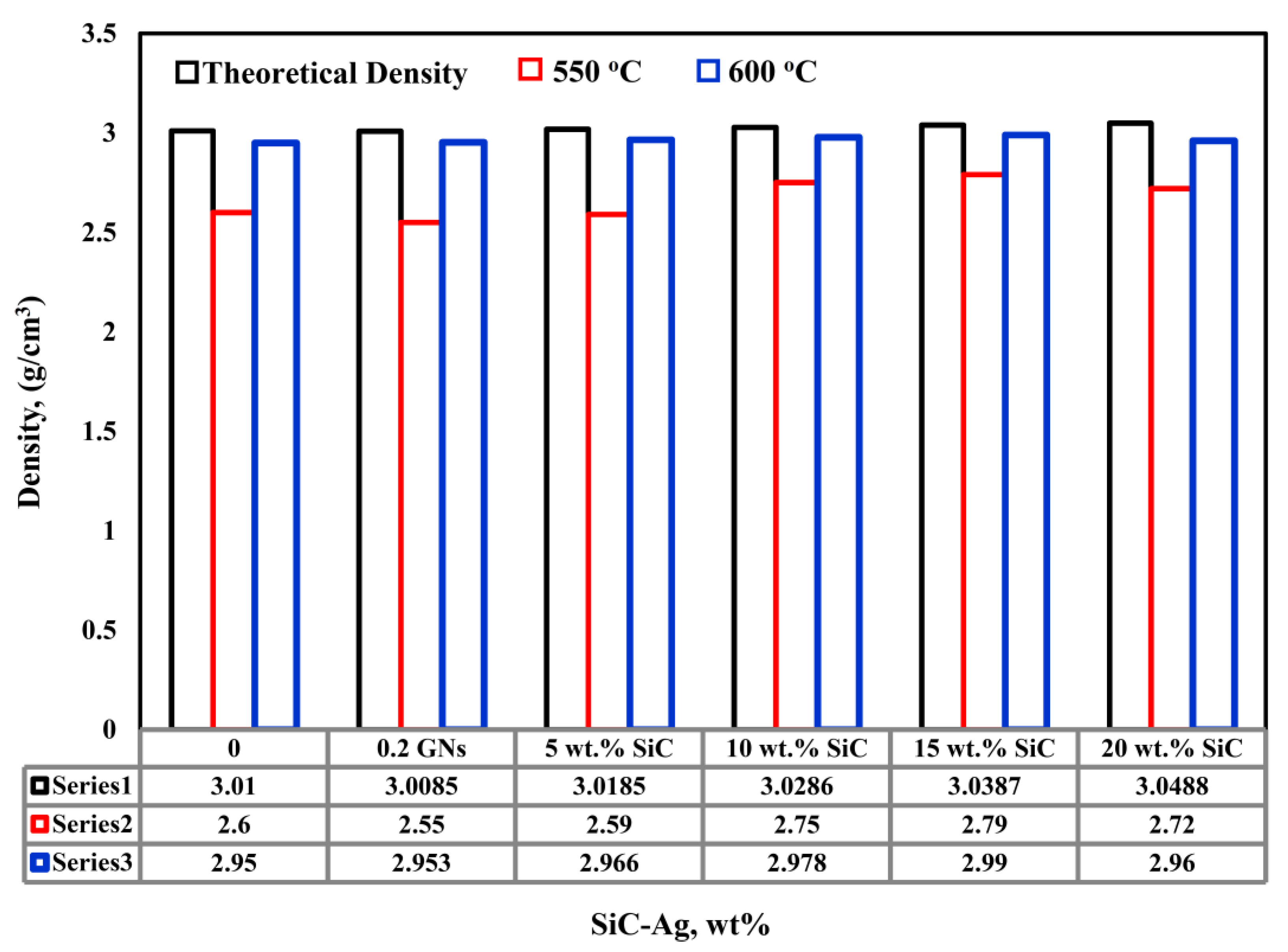
3.4. Density Measurement

Figure 4 shows the variation in the theoretical and actual density of Al caused by adding Ni, GNs, and different weight percentages of SiC at consolidation temperatures of 550 °C and 600 °C. The theoretical density calculations show that the density of the aluminum increased with the addition of Ni and decreased with the addition of GNs. Moreover, the density of Al-5Ni-0.2G increased gradually when increasing the content of the SiC-Ag particles up to 15 wt%. An increase or a decrease in theoretical density is related to the density values of the matrix and the reinforcement. When the reinforcement’s density is higher than the matrix’s density, the composite’s density will increase. This is because the higher-density particles replace the lower-density ones. Three observations can be made from the figure. The first is that the density values of the samples consolidated at 600 °C are higher than those consolidated at 550 °C. The second is the gradual increase in density values when increasing the SiC content to 15 wt%, which then decrease at 20 wt%. The third observation is the slight increase in and the convergence of the density values. At 600 °C, the fabricated nanocomposites’ actual density takes the same trend as the nanocomposite powders’ theoretical density. The density increased when strengthening the aluminum with Ni, GNs, and up to 15 wt% SiC-Ag. Regardless of the decrease in the Al-5Ni nanocomposite matrix’s theoretical density with the addition of 0.2 GNs, the actual density increased for the same sample. The increase in the Al-5Ni nanocomposite matrix’s actual density may be due to the micro-pores being filled with the graphene layer during the hot pressing process. The increase in the Al-5Ni-0.2GNs nanocomposite’s density produced by increasing the SiC-Ag content can be attributed to the efficient densification of the hot pressing process that uses high pressure during thermo-mechanical consolidation. Hot pressing helps to increase the number of interactions between particles, facilitating the high-temperature bonding of neighboring particles. In addition, it cracks any oxidation layer on the particles’ surface that may disengage the excellent adhesion between them [47]. Applying pressure to the thermal load helps the aluminum flow and fill any gaps or voids and, consequently, to achieve the highest degree of densification. The decrease in the density of the 20 wt% SiC-Ag sample may be attributed to the production of agglomerations at this percentage that lead to the micro-pores shown in Figure 3. This participates in reducing the density of all the produced nanocomposites. Overall, the good densification results obtained for all compositions confirm that the selected temperature for the hot pressing process allowed for the plastic flow of aluminum under pressure.

3.5. Hardness Measurements

The hardness values of the investigated samples are presented in Figure 5. This test was performed to study the effect of Ni, GNs, and SiC-Ag wt.% on the plastic deformation of the aluminum matrix. The aluminum metal recorded a hardness of 31 HV [35]. Due to the addition of 5 wt% Ni, the hardness increased to 51.5 HV. This improvement may be due to the hardness of the Ni being higher than that of the Al and the production of Al3Ni and Ni3C intermetallic compounds. Yunya Zhang et al. [61] investigated the hardness behavior of Ni, Ni/Ni3C composites, and Ni-Ti-Al/Ni3C composites at different temperatures using a Vickers hardness tester. The result revealed that the formation of Ni3C enhanced the hardness of the Ni/Ni3C composite to 3.7 GPa compared with 2 GPa for the pure Ni at room temperature and the hardness decreased with increasing temperature. The addition of 0.2 wt% GNs to the Al/5Ni increased the hardness value to 77.8 HV (a 47.38% increment). Upon adding the SiC-Ag to the Al-5Ni-0.2 GNs matrix, the hardness increased gradually, and the 20 wt.% sample recorded a hardness of 121.6 HV (a 56.29% increment). The results reveal the importance of graphene as a strengthening material for the aluminum matrix, as 0.2 wt% graphene enhanced the hardness by 47.38%. This increment can be attributed to the characteristics of graphene. The graphene layer has a large surface area and nanoscale thickness. It represents a plane of atoms in the matrix. Because the high bonding strength between its atoms prevents the indenter from penetrating the matrix, the hardness increased. The addition of 20 wt% SiC enhanced the hardness by 56.29%. This improvement in the percentage is not high compared with the high content of SiC. This low degree of improvement may be due to the SiC’s accumulation on the aluminum grain boundaries, which weakens the bonding between the particles. In addition to the effect of the SiC ceramic material, the X-ray analysis shows that new intermetallic compounds formed during the preparation process. Intermetallic compounds are characterized by high hardness, which also increases the aluminum matrix’s hardness [47].

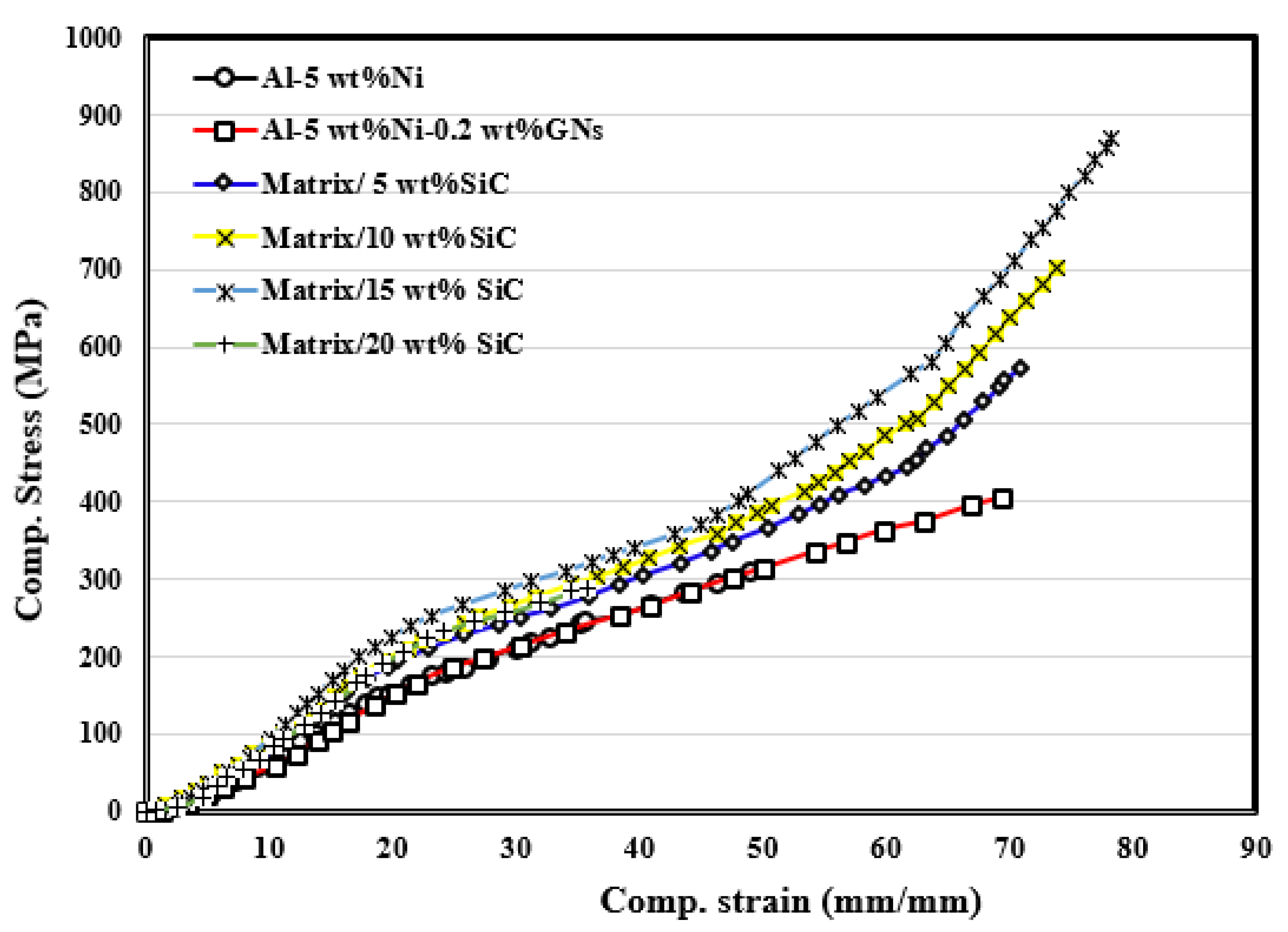
3.6. Compressive Strength

Figure 6 illustrates the stress–strain curves of the fabricated nanocomposites due to applying compression forces at room temperature. The maximum stress and total strain for each tested material are summarized in Table 3. As shown in the table, the compressive strength of the fabricated materials increased upon strengthening the aluminum matrix with 5 wt% Ni and 0.2 wt% GNs, respectively. Reinforcing the Al with SiC increased the maximum compressive strength gradually up to 15 wt% SiC, which then decreased for the 20 wt% SiC sample. According to the parameters that affect the powder metallurgy product, three main factors explain the gradual increase in compressive strength (Cs) with 5 wt% Ni, 0.2 wt% GNs, and up to 15 wt% SiC. The first is the strengthening effect of grain size according to the Hall–Petch equation, the second is the Orowan strengthening impact, which is related to the excellent distribution of the matrix’s reinforcement, and the third is the strong cohesion force between the Al matrix and the ceramic reinforcement, which helps transfer the load from the ductile matrix to the rigid reinforcement. The Al3Ni and Ni3C intermetallic compounds on the grain boundaries of the Al particles and the GNs layers on the Al matrix act as load bearers and prevent cracks from appearing during the application of load, leading to an increase in the compressive strength of fabricated nanocomposites [52,62]. Yunya Zhang et al. [61] showed that the small grains and interstitial solution atoms of the Ni3C in a Ni/Ni3C composite prohibited the propagation of dislocations and enhanced the Ni matrix. In total, a 73% increase in strength with a 28% reduction in flexibility led to a 44% improvement in toughness. The decrease in the maximum compressive strength at 20 wt% SiC may be due to its accumulation at the Al matrix’s grain boundaries. Regardless of the amount of SiC, the model (Al-5 wt% Ni-0.2 wt% GNs) was reinforced with, no cracks or fractures propagated during the compression test, indicating that the fabricated samples had high toughness. The recorded total strain values revealed that the real strain increased with the addition of Ni, GNs, and up to 15 wt% SiC.

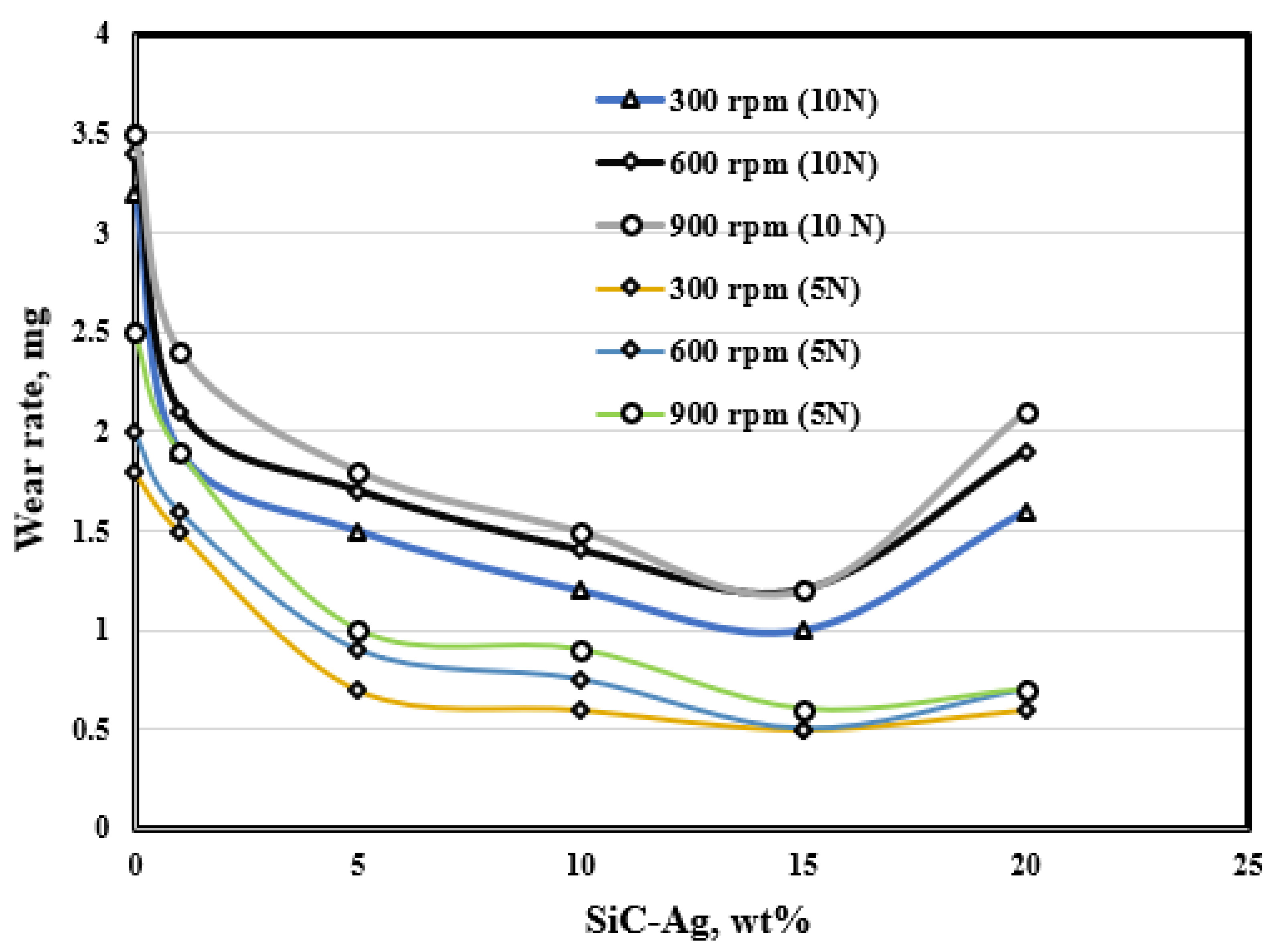
3.7. Wear Measurements

The influence of SiC content on the wear rate of the hybrid Al-5Ni-0.2GNs matrix at different sliding speeds and different loads for 10 min is shown in Figure 7. The results reveal that the wear rate decreased upon the addition of 5 wt% Ni, 0.2 wt% GNs, and up to 15 wt% SiC-Ag and then increased at 20 wt% SiC. Graphene nanosheets are hard ceramic materials with superior mechanical properties; reinforcing an Al matrix with them makes sliding more challenging, as shown in the hardness measurements (Figure 5), consequently increasing the wear resistance. Additionally, the agglomeration of GNs layers on the Al matrix’s surface made it slide easily with a low wear rate. The SiC ceramic material helps improve the wear resistance as it confers strength on the ductile Al. The increase in the wear rate at 20 wt% SiC may be related to the agglomeration of the SiC at the grain boundaries of the Al matrix, which weakened the bonding strength between the particles and, consequently, increased the wear rate. The wear rate increased upon increasing the applied load. The application of load increases the contact area between the frictional parts and increases the wear rate. An essential phenomenon was also observed in which the wear rate increased as the sliding speed increased. As the sliding speed increased, the track of the sample on the frictional parts increased and, consequently, the wear rate increased [51].

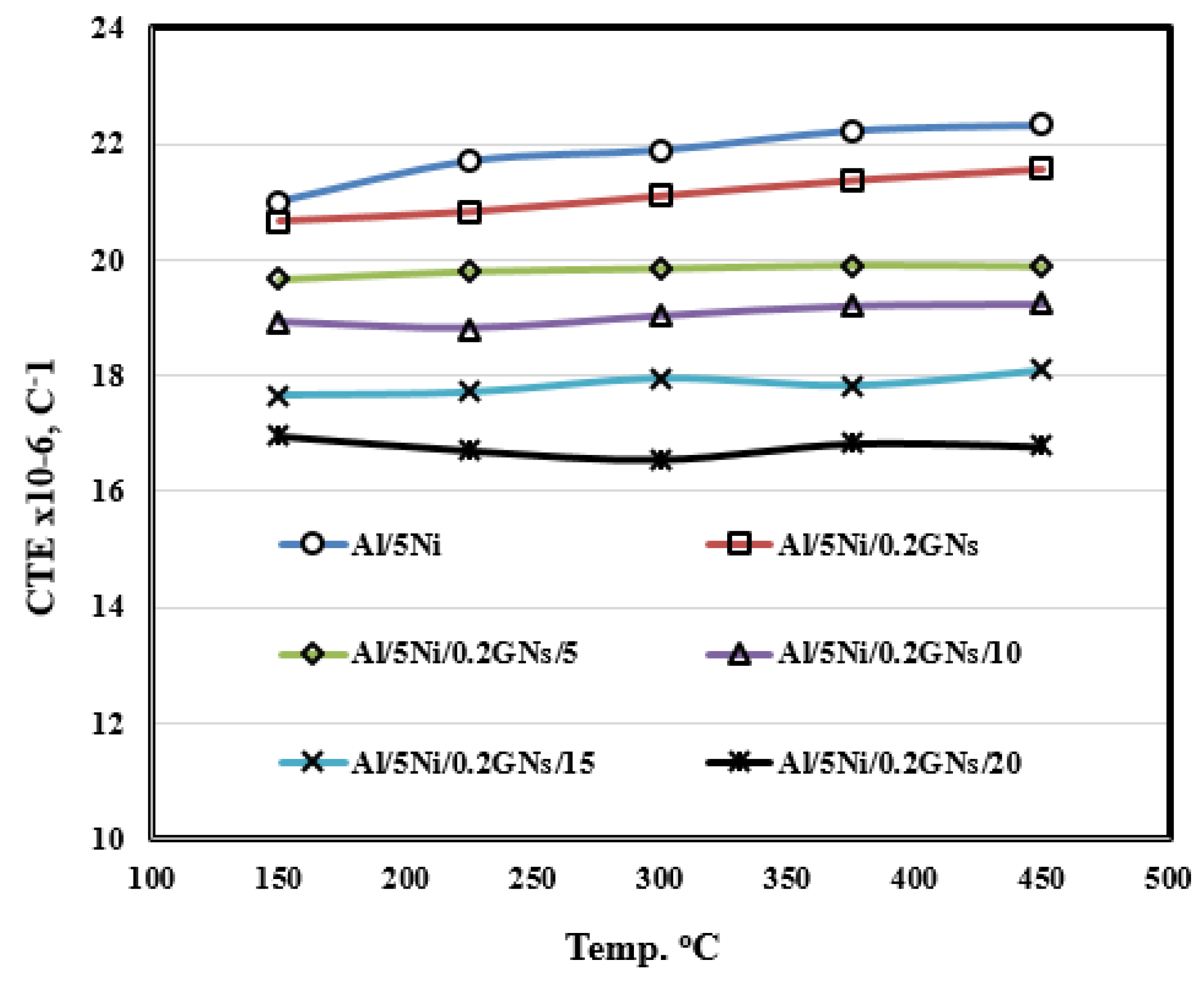
3.8. Thermal Expansion Estimation

The coefficient of thermal expansion (CTE) was determined in order to predict the fabricated samples’ behavior under different applied thermal loads. It is expressed as the change in the material’s dimensions as a function of temperature. The thermal expansion behavior depends on factors such as the type, microstructure, and percentage of the reinforcement, the morphology of the matrix, the thermal history, and the presence and number of pores. Additionally, the internal stress between the model and the support affects the thermal expansion behavior. Figure 8 illustrates the CTE of the fabricated samples at different heating temperatures. The CTE of the fabricated pieces changed upon the application of heat. The CTE increased upon increasing the heating temperature. As shown in the figure, the CTE of the Al-5Ni-0.2GNs sample decreased upon increasing the SiC content for reasons related to the low thermal expansion of the SiC and the porosity of the SiC at high contents. High amounts of SiC particles increase the restriction on the aluminum matrix and reduce the composites’ expansion [35].

4. Electrochemical Investigation

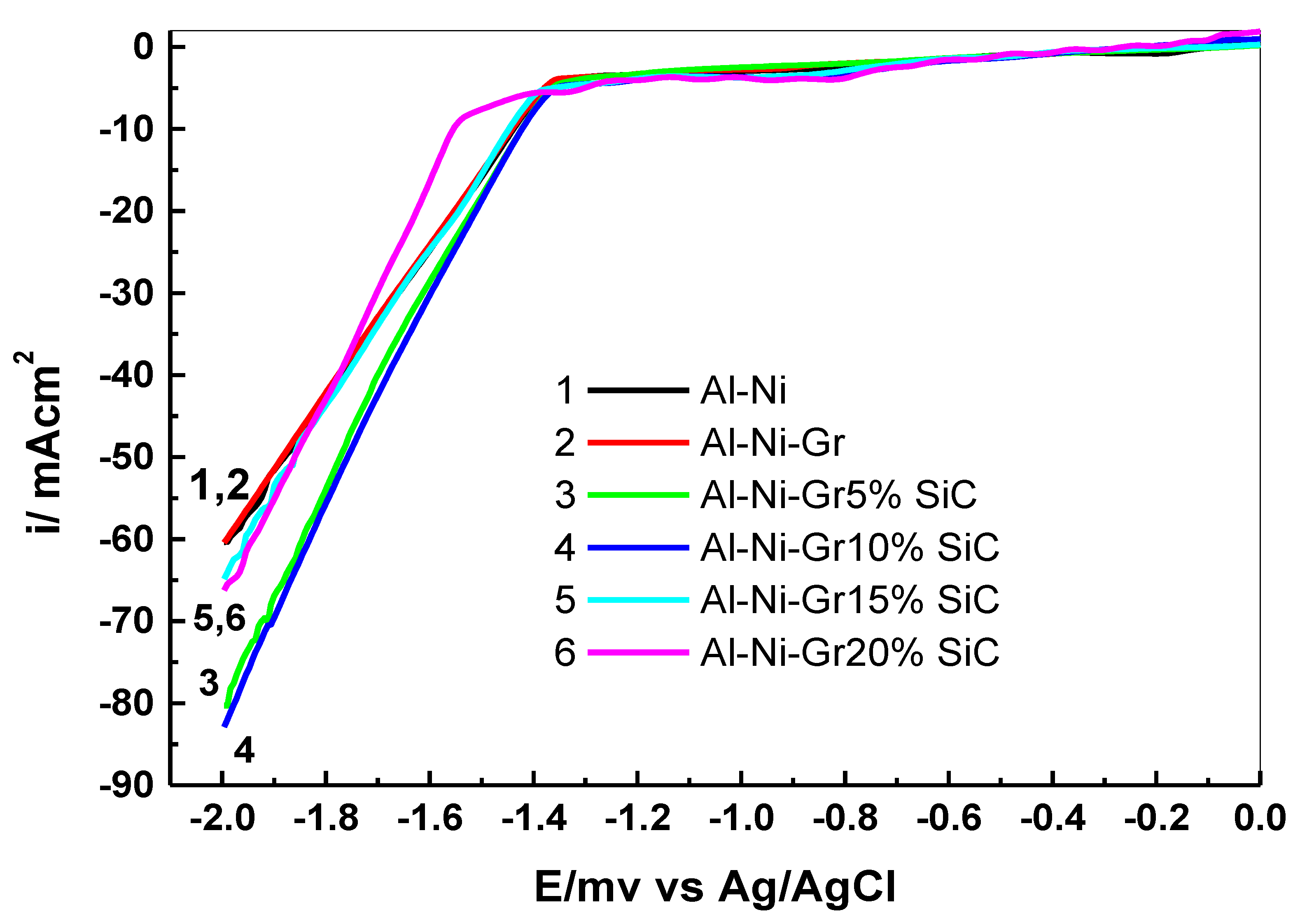
4.1. Linear Sweep Voltammetric Study

We tested the synthesized Al-Ni-GNs substrates doped with different SiC ratios (5, 10, 15, and 20 wt%) by the electrodeposition of a ZnO layer on these substrates. We also studied factors affecting the deposition of ZnO by using linear sweep voltammetry and the potentiostatic technique.
Figure 9 shows the current–potential curves recorded with the Al-Ni-GNs-SiC substrates in a 0.1 M Zn (NO3)2 and 0.05 M KNO3 solution. Linear sweep voltammetric studies were performed in the range of 0 to −2000 mV (versus the Ag/AgCl reference electrode) using a scan rate (SR) of 10 mV/s. During electrodeposition, nitrate ions are used as oxygen precursors. The cathodic deposition of ZnO film in a nitrate bath proceeds via the reduction of nitrate ions. The resulting Zn (OH)2 ions react with Zn+2 ions to form a hydroxide cathode. After that, Zn (OH)2 is spontaneously dehydrated into ZnO [61]. The produced LSV curves for the pure Al-Ni and Al-Ni-GNs substrates are shown in Figure 1 (curves 1 and 2). These curves are similar and indicate similar behavior. The two curves are characterized by an initial weak cathodic deposition current at −5 mA cm−2, associated with an applied potential of −800 mV.
On increasing the potential sweep, the cathode deposition current density begins to increase at a potential of −1350 mV. After that, at a potential of −1350 mV, the cathodic current sharply increases up to −60 mA cm−2. This sharp increase in the cathodic current corresponds to nucleation (a crystallization step) and the electrodeposition of a thin ZnO layer on the tested Al-Ni and Al-Ni-GNs substrates. It is clear from all of the linear sweep curves that the tested Al-Ni and Al-Ni-GNs substrates have an identical ZnO deposition behavior. Curve 3 is associated with the presence of 5 wt% SiC in the Al-Ni-GNs electrode. On this curve, the deposition of ZnO film starts at a potential of −750 mV, earlier than on curves 1 and 2. After that, at a potential of −1350 mV, the cathodic current sharply increases up to −80 mA cm−2. A similar behavior was observed with the presence of 10 wt% SiC (curve 4), but a sharp increase in the cathodic current up to −85 mA cm−2 takes place. This indicates that the 5 wt% SiC in the Al-Ni-GNs composite (substrate) enhanced the cathodic deposition current by 20 mA/cm2 and decreased the substrate’s resistance to electrodeposition.
Moreover, the 10 wt% SiC in the Al-Ni-GNs composite (substrate) improved the cathodic deposition current by 25 mA cm−2 and decreased the resistance of the substrate to electrodeposition. The presence of the 10 wt% SiC in the Al-Ni-GNs composite improved the electrodeposition of the ZnO film to a greater degree than the presence of 5 wt% SiC. The presence of 10 wt% SiC recorded a higher deposition current (−85 mA cm−2) and a higher rate of deposition than the −80 mA cm−2 for 5 wt% SiC. On the other hand, with 15 wt% and 20 wt% SiC in the Al substrate (curves 5 and 6, respectively), the LSV curves are similar and indicate the same electrochemical deposition behavior. An initial deposition current of −5 mA cm−2 characterizes the two curves and is associated with an applied potential of −750 mV. The deposition current density also begins to increase at a potential of −1350 mV, followed by a sharp increase in the cathodic current up to −65 mA cm−2. In general, the presence of SiC in Al-Ni-GNs substrates causes a positive shift in the electrodeposition potential and shifts the film deposition current toward more negative values. This indicates that the presence of SiC in an Al-Ni-GNs substate improves the conductivity and decreases the resistance of the substrate to the electrochemical deposition process. Moreover, the 10 wt% SiC in the Al-Ni-GNs composite improved the electrodeposition of the ZnO film to a greater degree than the 15 and 20 wt% SiC. Additionally, the 5 wt% SiC in the Al-Ni-GNs composite enhanced the substrate’s activity toward ZnO film deposition to a greater degree than the 15 and 20 wt% SiC. Each Al substrate has its own potential energy and conductivity. The conductivity is strongly related to the potential energy of the substrate. The ZnO crystal size is strongly affected by the conductivity of the substrate and its potential energy. The presence of 10 wt% SiC in the Al-Ni-GNs electrode improved the electrode’s potential energy toward the ZnO deposition process and may have enhanced its conductivity.

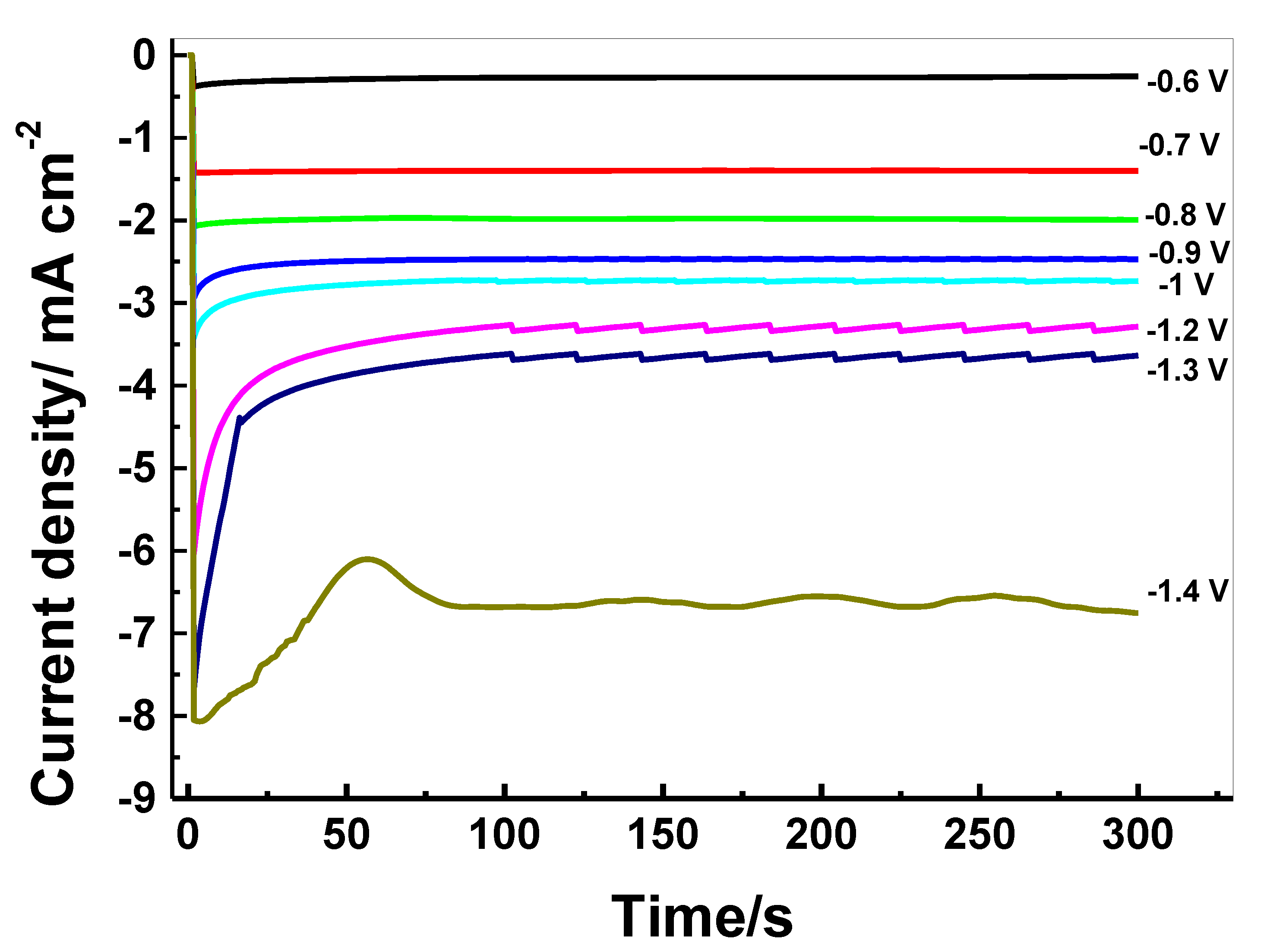
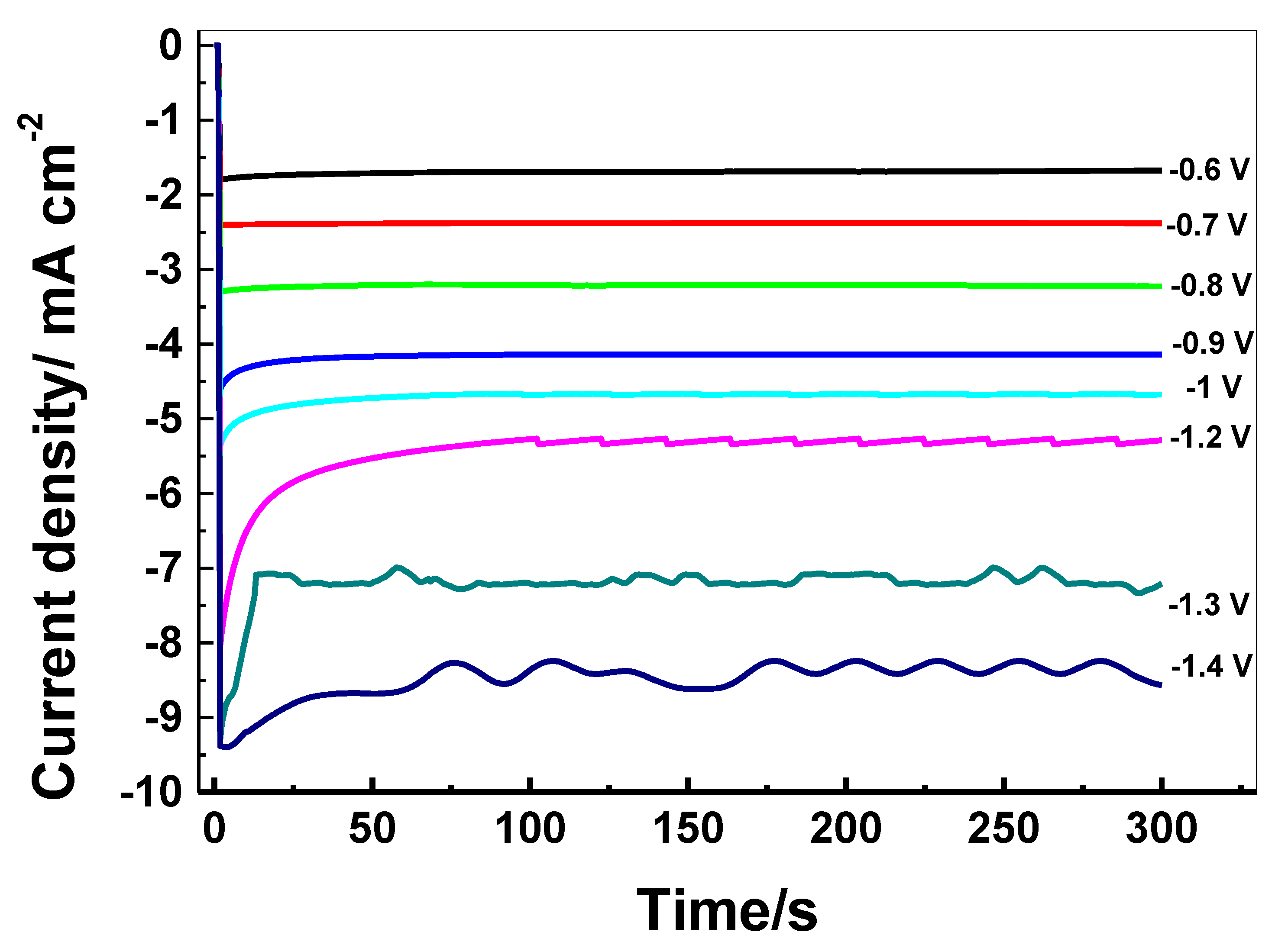
4.2. Potentiostatic Study

Figure 10 presents the potentiostatic current versus time (I-t) transients for the growth and nucleation of ZnO with the Al-Ni-GNs substrate at potentials ranging between −600 and −1400 mV. The eight curves shown in the Figure were recorded with the Al-Ni-GNs substrate in a deposition solution of 0.1 M Zn (NO3)2 and 0.05 M KNO3 under the same conditions.
The eight curves show that, immediately after the application of potential, the cathodic current rapidly increased because the nucleation of ZnO crystals started. Each crystal’s three-dimensional growth rapidly increased the active surface area. The current transient is typical of a three-dimensional electro-crystallization growth process [63,64]. The transients were divided into three regions. The first region corresponds to short time periods (t < 0.5 s). In this region, the decrease in the cathodic current density was related to the charging of a double layer. The second region (1 to 50 s) relates to the crystal nucleation process and the crystals formed in the first region. The cathodic current densities of this region achieve their maximum value. The third region corresponds to long time periods (more than 50 s) and a decline in the current density, which represents the diffusion process [63,65]. A further increase in the deposition time (more than 60 s) causes a leveling out of the current density value (to almost a constant plateau). The current behavior for the eight curves in Figure 10 (the eight plateaus) becomes similar because the eight substrates are completely covered by the ZnO layer, which is especially visible. The figure shows the current plateau with a value of about −0.28 mA cm−2 at a potential of −600 mV, a current plateau with a value of about −1.4 mA cm−2 at a potential of −700 mV, a current plateau with a value of about −1.94 mA cm−2 at a potential of −800 mV, a current plateau with a value of about −2.5 mA cm−2 at a potential of −900 mV, a current plateau with a value of about −2.7 mA cm−2 at a potential of −1000 mV, a current plateau with a value of about −3.2 mA cm−2 at a potential of −1200 mV, a current plateau with a value of about 3.66 mA cm−2 at a potential of −1300 mV, and a current plateau with a value of about −6.6 mA cm−2 at a potential of −1400 mV.
Figure 11 depicts the current–time (I-t) transient curves for the growth of ZnO with the Al-Ni-Gr-10% SiC substrate at a constant potential ranging between −600 and −1400 mV. The figure displays a current plateau with a value of about −1.68 mA cm−2 at a potential of −600 mV, a current plateau with a value of about −2.38 mA cm−2 at a potential of −700 mV, a current plateau with a value of about −3.19 mA cm−2 at a potential of −800 mV, a current plateau with a value of about −4.14 mA cm−2 at a potential of −900 mV, a current plateau with a value of about −4.5 mA cm−2 at a potential of −1000 mV, a current plateau with a value of about −5.3 mA cm−2 at a potential of −1200 mV, a current plateau with a value of about −7.15 mA cm−2 at a potential of −1300 mV, and a current plateau with a value of about −8.33 mA cm−2 at a potential of −1400 mV. Figure 10 and Figure 11 indicate that the increase in the current density as the potential increases could be related to the complete deposition of the ZnO film. Additionally, during the nucleation process, the electrochemical behavior was found to depend on the applied potential in both tested substrates (Al-Ni-Gr and Al-Ni-Gr-10% SiC). The presence of 10 wt% SiC in the Al-Ni-Gr substrate (Figure 11) is associated with higher current–time transient values (i-t plateaus) than the SiC-free substrate (Figure 10). This indicates that the Al-Ni-GN-10% SiC substrate is more conductive and less resistive than the Al-Ni-GN substrate.

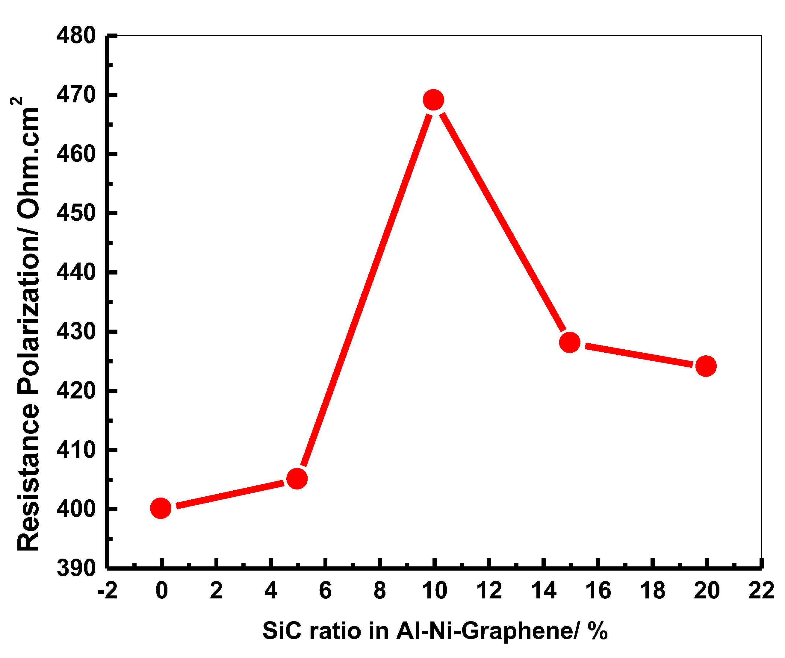
4.3. Ohmic Resistance Polarization Study

The corrosion behavior of six different Al-Ni-Gr substrates doped with different composite SiC percentages was tested using a 0.1 M Zn(NO3)2 + 0.05 M KNO3 bath under the same conditions. The polarization resistance (Rp) is the transition resistance between the Al-Ni-Gr electrode with the composite SiC and the electrolyte. A high Rp value of a metal electrode implies high abrasion and erosion resistance, while a low Rp value implies low abrasion resistance. Thus, the polarization resistance is the ratio of the applied potential to the resulting current response. This resistance is inversely related to a uniform corrosion rate. The ohmic polarization resistance is vital to determining and testing the abrasion behavior of an Al substrate doped with SiC. The polarization resistance behaved like an abrasion resistor for the tested Al electrodes. Figure 12 shows that the ohmic resistance polarization values increase steeply with increasing SiC wt% in the Al samples from 0 to 5 wt% SiC, recording a value of 412 Ohms cm2 with 5 wt% SiC. After that, the ohmic resistance polarization attained a maximum value of 469 ohms cm2 with 10 wt% SiC.
On the other hand, a further increase in the SiC ratio in the Al-Ni-GNs substrate to 15% decreased the ohmic resistance polarization gradually to 428 Ohms cm2. The ohmic resistance polarization gradually decreased to 424 ohms cm2 upon increasing the SiC weight percentage to 20%. Finally, the results reveal that the Al-Ni-GNs sample with 10 wt% SiC showed a higher maximum ohmic resistance polarization value (469 ohms. cm2) than the Al-Ni-GNs-SiC-free sample (400 ohms. cm2).

5. Conclusions

In this work, an Al matrix was reinforced with Ni, GNPs, and different amounts of SiC using the powder technology–hot pressing technique. According to the obtained results, it can be concluded that:
  • Ni was successfully precipitated by the electroless chemical deposition technique on the nano scale;
  • All samples were successfully prepared by powder metallurgy–hot pressing at 600 °C for 30 min;
  • XRD revealed the formation of Al3Ni and Ni3C intermetallic compounds;
  • The density increased upon strengthening the aluminum with Ni, GNs, and up to 15 wt% SiC-Ag;
  • The Al-5Ni recorded a hardness of 51.5 HV. The addition of 0.2 wt% GNs increased the hardness value by 47.38%. The addition of SiC-Ag gradually increased the hardness. The 20 wt% SiC sample recorded a hardness of 121.6 HV with a 56.29% increment;
  • The results showed that the wear rate decreased upon the addition of 5 wt% Ni, 0.2 wt% GNs, and SiC-Ag content up to 15 wt% and then increased at 20 wt% SiC;
  • The high mechanical properties of GNs and SiC, the fair distribution, and the excellent adhesion to Al explained the gradual increases in compressive strength (Cs) with 5 wt% Ni, 0.2 wt% GNs, and up to 15 wt% SiC;
  • Due to the excellent adhesion between the Ni, GNs, SiC, and the Al matrix and their low thermal expansion, the CTE of the new nanocomposites decreased;
  • The results indicate that the presence of 10 wt% SiC in the Al-Ni-GNs substrate decreased the substrate’s resistance to the electrochemical deposition process and consequently improved the electrodeposition of ZnO film to a greater degree than the 15 and 20 wt% SiC; and
  • The results suggest that the Al-Ni-GNs-10% SiC substrate achieved the maximum ohmic resistance polarization value (469 Ohms cm2) compared with the 400 Ohms cm2 of the Al-Ni-GNs-SiC-free sample.

Author Contributions

O.A.E. (Conceptualization, methodology, resources, project administration, and writing—original draft preparation), H.M.Y. (project administration, methodology, investigation, and writing—original draft preparation), A.A.I. (Investigation), A.M.E. (data curation, and writing—review and editing), E.M.E. (investigation, writing—review and editing), and A.A.M. (Investigation, and writing—review and editing). All authors have read and agreed to the published version of the manuscript.

Funding

This research received no external funding.

Conflicts of Interest

The authors declare no conflict of interest.

References

  1. Deaquino-Lara, R.; Gutierrez, E.; Estrada-Guel, I.; Hinojosa-Ruiz, G.; Sanchez, E.G.; Herrera-Ramirez, J.; Perez-Bustamante, R.; Sánchez, R.M. Structural characterization of aluminium alloy 7075–graphite composites fabricated by mechanical alloying and hot extrusion. Mater. Des. 2014, 53, 1104–1111. [Google Scholar] [CrossRef]
  2. Baradeswaran, A.; Perumal, A.E. Wear and mechanical characteristics of Al 7075/graphite composites. Compos. Part B Eng. 2014, 56, 472–476. [Google Scholar] [CrossRef]
  3. Ibrahim, I.A.; Mohamed, F.A.; Lavernia, E.J. Particulate reinforced metal matrix composites—A review. J. Mater. Sci. 1991, 26, 1137–1156. [Google Scholar] [CrossRef]
  4. Barakat, W.S.; Elkady, O.; Abuoqail, A.; Yehya, H.; El-Nikhaily, A. Effect of Al2O3 coated Cu nanoparticles on properties of Al/Al2O3 composites. J. Pet. Min. Eng. 2020, 22, 53–60. [Google Scholar] [CrossRef]
  5. Mansour, N.S.S.; Yehia, H.M.; Ali, A.I. Graphene reinforced copper matrix nano-composite for resistance seam welding electrode. Bull. Tabbin Inst. Metall. Stud. (TIMS) 2021, 109, 25–34. [Google Scholar] [CrossRef]
  6. Li, Y.; Zhao, J.; Tang, C.; He, Y.; Wang, Y.; Chen, J.; Mao, J.; Zhou, Q.; Wang, B.; Wei, F.; et al. Highly Exfoliated Reduced Graphite Oxide Powders as Efficient Lubricant Oil Additives. Adv. Mater. Interfaces 2016, 3, 1–8. [Google Scholar] [CrossRef]
  7. Zidan, H.M.; Hegazy, M.; Abd-Elwahed, A.; Yehia, H.M.; El Kady, O.A. Investigation of the Effectuation of Graphene Nanosheets (GNS) Addition on the Mechanical Properties and Microstructure of S390 HSS Using Powder Metallurgy Method. Int. J. Mater. Technol. Innov. 2021, 1, 52–57. [Google Scholar] [CrossRef]
  8. Worsley, M.; Olson, T.Y.; Lee, J.; Willey, T.; Nielsen, M.H.; Roberts, S.K.; Pauzauskie, P.J.; Biener, J.; Satcher, J.H.; Baumann, T.F. High Surface Area, sp2-Cross-Linked Three-Dimensional Graphene Monoliths. J. Phys. Chem. Lett. 2011, 2, 921–925. [Google Scholar] [CrossRef] [PubMed]
  9. Kausar, A.; Rafique, I.; Anwar, Z.; Muhammad, B. Perspectives of Epoxy/Graphene Oxide Composite: Significant Features and Technical Applications. Polym. Technol. Eng. 2015, 55, 704–722. [Google Scholar] [CrossRef]
  10. Kumar, S.J.N.; Keshavamurthy, R.; Haseebuddin, M.R.; Koppad, P. Mechanical Properties of Aluminium-Graphene Composite Synthesized by Powder Metallurgy and Hot Extrusion. Trans. Indian Inst. Met. 2017, 70, 605–613. [Google Scholar] [CrossRef]
  11. Geim, A.K. Graphene: Status and Prospects. Science 2009, 324, 1530–1534. [Google Scholar] [CrossRef] [PubMed] [Green Version]
  12. Li, X.; Zhu, Y.; Cai, W.; Borysiak, M.; Han, B.; Chen, D.; Piner, R.D.; Colombo, L.; Ruoff, R.S. Transfer of Large-Area Graphene Films for High-Performance Transparent Conductive Electrodes. Nano Lett. 2009, 9, 4359–4363. [Google Scholar] [CrossRef] [PubMed]
  13. Tang, C.; Wang, H.-F.; Huang, J.-Q.; Qian, W.; Wei, F.; Qiao, S.-Z.; Zhang, Q. 3D Hierarchical Porous Graphene-Based Energy Materials: Synthesis, Functionalization, and Application in Energy Storage and Conversion. Electrochem. Energy Rev. 2019, 2, 332–371. [Google Scholar] [CrossRef]
  14. Jeon, C.-H.; Jeong, Y.-H.; Seo, J.-J.; Tien, H.N.; Hong, S.-T.; Yum, Y.-J.; Hur, S.-H.; Lee, K.-J. Material properties of graphene/aluminum metal matrix composites fabricated by friction stir processing. Int. J. Precis. Eng. Manuf. 2014, 15, 1235–1239. [Google Scholar] [CrossRef]
  15. Stankovich, S.; Dikin, D.A.; Dommett, G.H.B.; Kohlhaas, K.M.; Zimney, E.J.; Stach, E.A.; Piner, R.D.; Nguyen, S.; Ruoff, R.S. Graphene-based composite materials. Nature 2006, 442, 282–286. [Google Scholar] [CrossRef]
  16. Bastwros, M.; Kim, G.-Y.; Zhu, C.; Zhang, K.; Wang, S.; Tang, X.; Wang, X. Effect of ball milling on graphene reinforced Al6061 composite fabricated by semi-solid sintering. Compos. Part B Eng. 2014, 60, 111–118. [Google Scholar] [CrossRef]
  17. Lei, Y.; Jiang, J.; Bi, T.; Du, J.; Pang, X. Tribological behavior of in situ fabricated graphene–nickel matrix composites. RSC Adv. 2018, 8, 22113–22121. [Google Scholar] [CrossRef] [Green Version]
  18. Hossam, M.Y.; Mohamed, M.; Allam, S.; Saleh, K. Fabrication of Aluminum Matrix Nanocomposites by Hot Compaction. J. Pet. Min. Eng. 2020, 22, 16–20. [Google Scholar] [CrossRef]
  19. Wang, J.; Li, Z.; Fan, G.; Pan, H.; Chen, Z.; Zhang, D. Reinforcement with graphene nanosheets in aluminum matrix composites. Scr. Mater. 2012, 66, 594–597. [Google Scholar] [CrossRef] [Green Version]
  20. Hu, Z.; Tong, G.; Lin, D.; Chen, C.; Guo, H.; Xu, J.; Zhou, L. Graphene-reinforced metal matrix nanocomposites—A review. Mater. Sci. Technol. 2016, 32, 930–953. [Google Scholar] [CrossRef]
  21. Haghighi, M.; Shaeri, M.H.; Sedghi, A.; Djavanroodi, F. Effect of Graphene Nanosheets Content on Microstructure and Mechanical Properties of Titanium Matrix Composite Produced by Cold Pressing and Sintering. Nanomaterials 2018, 8, 1024. [Google Scholar] [CrossRef] [PubMed] [Green Version]
  22. Li, Z.; Fan, G.; Tan, Z.; Guo, Q.; Xiong, D.; Su, Y. Uniform dispersion of graphene oxide in aluminum powder by direct electrostatic adsorption for fabrication of graphene/aluminum composites. Nanotechnology 2014, 25, 325601. [Google Scholar] [CrossRef]
  23. Zhang, J.; Chen, Z.; Zhao, J.; Jiang, Z.; Zhao, C.J.; Jiang, Z. Microstructure and mechanical properties of aluminium-graphene composite powders produced by mechanical milling. Mech. Adv. Mater. Mod. Process. 2018, 4, 4. [Google Scholar] [CrossRef]
  24. Tabandeh-Khorshid, M.; Omrani, E.; Menezes, P.L.; Rohatgi, P.K. Tribological performance of self-lubricating aluminum matrix nanocomposites: Role of graphene nanoplatelets. Eng. Sci. Technol. Int. J. 2016, 19, 463–469. [Google Scholar] [CrossRef] [Green Version]
  25. Zhang, W.L.; Gu, M.Y.; Wang, D.Z.; Yao, Z.K. Rolling and annealing textures of a SiCw/Al composite. Mater. Lett. 2004, 58, 3414–3418. [Google Scholar] [CrossRef]
  26. Rashad, M.; Pan, F.; Tang, A.; Asif, M.; She, J.; Gou, J.; Mao, J.; Hu, H. Development of magnesium-graphene nanoplatelets composite. J. Compos. Mater. 2014, 49, 285–293. [Google Scholar] [CrossRef]
  27. Peter, N.; Omayma, E.; Hossam, M.Y.; Atef, S.H.; Mohsen, A.H. Effect of Bimodal-Sized Hybrid TiC-CNT Reinforcement on the Mechanical Properties and Coefficient of Thermal Expansion of Aluminium Matrix Composites. Met. Mater. Int. 2021, 27, 753–766. [Google Scholar]
  28. Nyanor, P.; El-Kady, O.; Yehia, H.M.; Hamada, A.S.; Nakamura, K.; Hassan, M.A. Effect of Carbon Nanotube (CNT) Content on the Hardness, Wear Resistance and Thermal Expansion of In-Situ Reduced Graphene Oxide (rGO)-Reinforced Aluminum Matrix Composites. Met. Mater. Int. 2019, 27, 1315–1326. [Google Scholar] [CrossRef]
  29. Elasser, A.; Chow, T. Silicon carbide benefits and advantages for power electronics circuits and systems. Proc. IEEE 2002, 90, 969–986. [Google Scholar] [CrossRef]
  30. Matsunami, H. Technological Breakthroughs in Growth Control of Silicon Carbide for High Power Electronic Devices. Jpn. J. Appl. Phys. 2004, 43, 6835–6847. [Google Scholar] [CrossRef]
  31. Kretz, F.; Gácsi, Z.; Kovács, J.; Pieczonka, T. The electroless deposition of nickel on SiC particles for aluminum matrix composites. Surf. Coatings Technol. 2004, 181, 575–579. [Google Scholar] [CrossRef]
  32. Fathy, A.; Sadoun, A.; Abdelhameed, M. Effect of matrix/reinforcement particle size ratio (PSR) on the mechanical properties of extruded Al-SiC composites. Int. J. Adv. Manuf. Technol. 2014, 73, 1049–1056. [Google Scholar] [CrossRef]
  33. Zhang, S.; Han, K.; Cheng, L. The effect of SiC particles added in electroless Ni–P plating solution on the properties of composite coatings. Surf. Coat. Technol. 2008, 202, 2807–2812. [Google Scholar] [CrossRef]
  34. Zhang, L.; He, X.; Qu, X.; Duan, B.; Lu, X.; Qin, M. Dry sliding wear properties of high volume fraction SiCp/Cu composites produced by pressureless infiltration. Wear 2008, 265, 1848–1856. [Google Scholar] [CrossRef]
  35. Abolkassem, S.A.; Elkady, O.A.; Elsayed, A.H.; Hussein, W.A.; Yehya, H.M. Effect of consolidation techniques on the properties of Al matrix composite reinforced with nano Ni-coated SiC. Results Phys. 2018, 9, 1102–1111. [Google Scholar] [CrossRef]
  36. Sikka, V.K.; Mavity, J.T.; Anderson, K. Processing of nickel aluminides and their industrial applications. In Proceedings of the Second International ASM Conference on High Temperature Aluminides and Intermetallics, San Diego, CA, USA, 16–19 September 1991; pp. 712–721. [Google Scholar]
  37. Koch, C. Intermetallic matrix composites prepared by mechanical alloying—A review. Mater. Sci. Eng. A 1998, 244, 39–48. [Google Scholar] [CrossRef]
  38. Carlson, T. Emerging applications of intermetallics N.S. Trans. Am. Math. Soc. 2016, 369, 2897–2916. [Google Scholar] [CrossRef] [Green Version]
  39. Hodge, A.; Dunand, D. Synthesis of nickel–aluminide foams by pack-aluminization of nickel foams. Intermetallics 2001, 9, 581–589. [Google Scholar] [CrossRef]
  40. Daoush, W.; Lim, B.K.; Mo, C.B.; Nam, D.H.; Hong, S.H. Electrical and mechanical properties of carbon nanotube reinforced copper nanocomposites fabricated by electroless deposition process. Mater. Sci. Eng. A 2009, 513, 247–253. [Google Scholar] [CrossRef]
  41. Yehia, H.M.; Elkady, O.A.; Reda, Y.; Ashraf, K.E. Electrochemical Surface Modification of Aluminum Sheets Prepared by Powder Metallurgy and Casting Techniques for Printed Circuit Applications. Trans. Indian Inst. Met. 2018, 72, 85–92. [Google Scholar] [CrossRef]
  42. Canakci, A.; Ozsahin, S.; Varol, T. Modeling the influence of a process control agent on the properties of metal matrix composite powders using artificial neural networks. Powder Technol. 2012, 228, 26–35. [Google Scholar] [CrossRef]
  43. Yehia, H.M.; El-Tantawy, A.; Ghayad, I.; Eldesoky, A.S.; El-Kady, O. Effect of zirconia content and sintering temperature on the density, microstructure, corrosion, and biocompatibility of the Ti–12Mo matrix for dental applications. J. Mater. Res. Technol. 2020, 9, 8820–8833. [Google Scholar] [CrossRef]
  44. Canakci, A.; Varol, T.; Erdemir, F. The Effect of Flake Powder Metallurgy on the Microstructure and Densification Behavior of B4C Nanoparticle-Reinforced Al–Cu–Mg Alloy Matrix Nanocomposites. Arab. J. Sci. Eng. 2015, 41, 1781–1796. [Google Scholar] [CrossRef]
  45. Hassan, M.; Yehia, H.; Mohamed, A.; El-Nikhaily, A.; Elkady, O. Effect of Copper Addition on the AlCoCrFeNi High Entropy Alloys Properties via the Electroless Plating and Powder Metallurgy Technique. Crystals 2021, 11, 540. [Google Scholar] [CrossRef]
  46. El-Tantawy, A.; El Kady, O.A.; Yehia, H.M.; Ghayad, I.M. Effect of Nano ZrO2 Additions on the Mechanical Properties of Ti12Mo Composite by Powder Metallurgy Route. Key Eng. Mater. 2020, 835, 367–373. [Google Scholar] [CrossRef]
  47. Yehia, H.M.; Allam, S. Hot Pressing of Al-10 wt% Cu-10 wt% Ni/x (Al2O3–Ag) Nanocomposites at Different Heating Temperatures. Met. Mater. Int. 2020, 27, 500–513. [Google Scholar] [CrossRef]
  48. Yehia, H.M.; Daoush, W.; Mouez, F.A.; El-Sayed, M.H.; El-Nikhaily, A.E. Microstructure, Hardness, Wear, and Magnetic Properties of (Tantalum, Niobium) Carbide-Nickel–Sintered Composites Fabricated from Blended and Coated Particles. Mater. Perform. Charact. 2020, 9, 543–555. [Google Scholar] [CrossRef]
  49. Yehia, H.M. Microstructure, physical and mechanical properties of the Cu/(WC-TiC-Co) nano-composites by the electro-less coating and powder metallurgy technique. J. Compos. Mater. 2019, 53, 1963–1971. [Google Scholar] [CrossRef]
  50. El-Kady, O.; Yehia, H.M.; Nouh, F. Preparation and characterization of Cu/(WC-TiC-Co)/graphene nano-composites as a suitable material for heat sink by powder metallurgy method. Int. J. Refract. Met. Hard Mater. 2019, 79, 108–114. [Google Scholar] [CrossRef]
  51. Yehia, H.M.; Abu-Oqail, A.; Elmaghraby, M.A.; Elkady, O.A. Microstructure, hardness, and tribology properties of the (Cu/MoS2)/graphene nanocomposite via the electroless deposition and powder metallurgy technique. J. Compos. Mater. 2020, 54, 3435–3446. [Google Scholar] [CrossRef]
  52. Yehia, H.M.; Nouh, F.; El-Kady, O. Effect of graphene nano-sheets content and sintering time on the microstructure, coefficient of thermal expansion, and mechanical properties of (Cu/WC-TiC-Co) nano-composites. J. Alloys Compd. 2018, 764, 36–43. [Google Scholar] [CrossRef]
  53. Yehia, H.M.; Daoush, W.M.; El-Nikhaily, A.E.; Yehia, H.M.; Daoush, W.M. Microstructure and physical properties of blended and coated (Ta, Nb) C/Ni cermets. Powder Metall. Prog. 2015, 15, 2. [Google Scholar]
  54. Mordechay, S.; Milan, P. Electroless Deposition of Nickel. Modern Electroplating, 5th ed.; Wiley: Hoboken, NJ, USA, 2010; pp. 447–485. [Google Scholar]
  55. Yehia, H.; El-Kady, O.; Abuoqail, A. Effect of diamond additions on the microstructure, physical and mechanical properties of WC-TiC-Co/Ni Nano-composite. Int. J. Refract. Met. Hard Mater. Elsevier 2018, 71, 198–205. [Google Scholar] [CrossRef]
  56. Kim, D.W.; Kim, K.T.; Kwon, G.H.; Song, K.; Son, I. Self-propagating heat synthetic reactivity of fine aluminum particles via spontaneously coated nickel layer. Sci. Rep. 2019, 9, 1–8. [Google Scholar] [CrossRef] [Green Version]
  57. Biswas, A.; Roy, S. Comparison between the microstructural evolutions of two modes of SHS of NiAl: Key to a common reaction mechanism. Acta Mater. 2003, 52, 257–270. [Google Scholar] [CrossRef]
  58. Dyer, T.S.; Munir, Z.A. The synthesis of nickel aluminides by multilayer self-propagating combustion. Met. Mater. Trans. A 1995, 26, 603–610. [Google Scholar] [CrossRef]
  59. Plazanet, L.; Nardou, F. Reaction process during relative sintering of NiAl. J. Mater. Sci. 1998, 33, 2129–2136. [Google Scholar] [CrossRef]
  60. Sina, H.; Surreddi, K.B.; Iyengar, S. Phase evolution during the reactive sintering of ternary Al-Ni-Ti powder compacts. J. Alloys Compd. 2016, 661, 294–305. [Google Scholar] [CrossRef]
  61. Zhang, Y.; Heim, F.M.; Bartlett, J.L.; Song, N.; Isheim, D.; Li, X. Bioinspired, graphene-enabled Ni composites with high strength and toughness. Sci. Adv. 2019, 5, eaav5577. [Google Scholar] [CrossRef] [PubMed] [Green Version]
  62. Hernández-Méndez, F.; Altamirano-Torres, A.; Miranda-Hernández, J.G.; Térres-Rojas, E.; Rocha-Rangel, E. Effect of Nickel Addition on Microstructure and Mechanical Properties of Aluminum-Based Alloys. Mater. Sci. Forum 2011, 691, 10–14. [Google Scholar] [CrossRef]
  63. Elsayed, E.; Harraz, F.A.; Saba, A. Nanocrystalline zinc oxide thin films prepared by electrochemical technique for advanced applications. Int. J. Nanoparticles 2012, 5, 136. [Google Scholar] [CrossRef]
  64. Pauporté, T.; Lincot, D. Electrodeposition of semiconductors for optoelectronic devices: Results on zinc oxide. Electrochim. Acta 2000, 45, 3345–3353. [Google Scholar] [CrossRef]
  65. Moharam, M.; Elsayed, E.; Nino, J.; Abou-Shahba, R.; Rashad, M. Potentiostatic deposition of Cu2O films as p-type transparent conductors at room temperature. Thin Solid Film. 2016, 616, 760–766. [Google Scholar] [CrossRef]
Figure 1. SEM (BSE) micrograph of pure Al, GNs, electroless-deposited Ni, and milled SiC powder.
Crystals 11 01142 g001
Figure 2. XRD patterns of consolidated samples at 600 °C.
Crystals 11 01142 g002
Figure 3. SEM (BSE) micrographs of fabricated samples.
Crystals 11 01142 g003
Figure 4. Density of the hybrid Al matrix reinforced with SiC-Ag.
Crystals 11 01142 g004
Figure 5. Hardness measurements of samples fabricated at 600 °C.
Crystals 11 01142 g005
Figure 6. Stress–strain curves of the fabricated nanocomposites.
Crystals 11 01142 g006
Figure 7. Wear rate (mg) of the fabricated materials at a load of 5 N and 10 N and different sliding speeds (600 rpm, 900 rpm, and 1200 rpm).
Crystals 11 01142 g007
Figure 8. Coefficient of thermal expansion (CTE) of samples fabricated at 600 °C.
Crystals 11 01142 g008
Figure 9. Current–potential curves recorded with various Al-Ni-Gr-SiC substrates.
Crystals 11 01142 g009
Figure 10. Current–time curves recorded with the Al-Ni-Gr cathode at a constant potential in an aqueous solution of 0.1 M Zn (NO3)2 and 0.05 M KNO3.
Crystals 11 01142 g010
Figure 11. Current–time curves recorded with the Al-Ni-Gr-10% SiC cathode at a constant potential.
Crystals 11 01142 g011
Figure 12. Variation in ohmic resistance polarization with different SiC weight percentages in the Al-Ni-Gr substrate for ZnO film.
Crystals 11 01142 g012
Table 1. Chemical composition of the bath for the electroless nickel plating process.
ElementConcentration
NiCl2.6H2O100 g/L
NH4Cl50 g/L
Potassium sodium tartrate80 g/L
pH~11
Temperature~94
Sodium hypophosphite90 g/L
Table 2. Composition of the nanocomposite specimens.
Sample No.Composition
S195 wt.% Al + 5 wt.% Ni
S299.8 wt.% (95%Al + 5% Ni) + 0.2% GNPs Base sample
S395 wt.% Base sample/5% SiC
S490 wt.% Base sample/10% SiC
S585 wt.% Base sample/15% SiC
S6 80% Base sample/20% SiC
Table 3. Compressive stress and strain of the tested samples.
Sample No.Comp. Strength MPaStrain
Al-5 wt% Ni311.8248.86
Al-5 wt% Ni-0.2 wt% GNs405.28169.47
Matrix/5 wt% SiC572.27770.89
Matrix/10 wt% SiC702.96973.88
Matrix/15 wt% SiC868.35278.266
Matrix/20 wt% SiC288.15835.83
Publisher’s Note: MDPI stays neutral with regard to jurisdictional claims in published maps and institutional affiliations.

