
Relationship between Structural Stiffness and Viscous Damping Coefficient in Reinforced Carbon Structure under Varying Carbon Fiber Angles


Department of Mechanical Design Engineering, Pukyong National University, Busan 48513, Korea
Crystals 2021, 11(10), 1252; https://0-doi-org.brum.beds.ac.uk/10.3390/cryst11101252
Submission received: 14 September 2021
/
Revised: 4 October 2021
/
Accepted: 14 October 2021
/
Published: 15 October 2021
(This article belongs to the Section Crystal Engineering)
Abstract
:A linearized dynamic model of a carbon-fiber-reinforced plastic (CFRP) structure can be formulated using the structural stiffness and viscous damping coefficient. The carbon fiber angle is an influential factor in determining the structural stiffness of CFRP structures by serially combining the stiffness of a binding matrix and that of a carbon fiber. The viscous damping coefficient of the CFRP structure is also highly sensitive to the carbon fiber angle; that is, it assumes a parallel series between the damping coefficient of the binding matrix and that of the carbon fiber. In this study, a sensitivity formula was derived to obtain the ratio of two parameters—the structural stiffness, and the viscous damping coefficient—by dividing all parameters by the value of the reference angle. The CFRP structure was chosen for a simple rectangular specimen with five carbon fiber angles, ranging from 0° (reference) to 90°. The identified modal parameters were used from the impact modal test conducted in a previous study. Sensitivity analysis was conducted for both the structural stiffness and the viscous damping coefficient. The sensitivity results revealed that the sensitivity index of the viscous damping coefficient was proportional to that of the structural stiffness. Even a small value of the viscous damping coefficient of the carbon fiber was sensitive to the CFRP structure because the carbon-fiber damping coefficient was parallel to the large damping coefficient of the binding matrix.
1. Introduction
Composite structures have many advantages over conventional ones from isotropic materials by reinforcements, that is, glass fiber or carbon fiber, in enhancing the mechanical properties. Carbon-fiber-reinforced plastic (CFRP) is a well-known composite owing to its superior strength-to-weight ratio, and many studies have thus investigated it [1,2,3]. With a focus on the anisotropic nature of the carbon fiber, the static properties of the CFRP structure were discussed in terms of the elastic modulus, Poisson’s ratio, and stress–strain relationship. CFRP materials are frequently used in industry because manufacturing costs are decreased with an increase in the mass-production volume. Several manufacturing processes have been studied, such as the effect of laser fabrication [4] and ultrathin electrospun nanofibers on multifunctional fiber-reinforced polymer composites [5]. Various applications of CFRP materials, including in the production of concrete columns [6], T-shaped beams [7], and Belleville springs [8] have been studied. Case studies have revealed the advantage of the reinforced composite structure in diverse industrial applications and the structure is expected to contribute to an emerging market for CFRP materials.
To identify the characteristics of CFRP structures, many test methods have been proposed that consider the directivity of responsible structures, which are different from the conventional structures formed with CFRP materials. With the consideration of the on- and off-axis loading conditions, the stress–strain relation has been investigated for a static behavior case [9]. In the case of dynamic behavior cases, the structural stiffness (or elastic modulus) and viscous damping properties have been investigated using a simple specimen [10,11,12,13]. Modal analysis is a widely used technique for the identification of modal parameters, both resonance frequencies and viscous damping coefficients, using frequency response functions (FRFs). These functions are based on the assumption that the dynamic characteristics of the target system form a linear system [14,15,16]. Recent studies estimated anisotropic material constants using modal tests [17]. Other studies investigated the modal parameters derived from both a finite element model (FEM) and from a boundary element method [18]. Other research has compared the difference in resonance frequencies between an experimental model and a FEM [19].
Some studies have focused on the sensitivity of modal parameters, the frequency resonance, the modal damping ratio, and the mode vector for different carbon fiber angles, as well as under other conditions, such as the temperature and the spectral loading effect. The effect of temperature was studied in terms of the variation of FRFs under a controlled environment temperature between −8 °C and 105 °C in a chamber [20]. The variation in the dynamic characteristics of the CFRP specimen was mainly caused by the variation in the mechanical properties of the binding matrix. Under the same uniaxial excitation condition, the dynamic behavior of the CFRP structure was investigated for different spectral loading patterns, random and harmonic, and the sensitivity difference was determined by comparing the normalized sensitivity indices [21]. A modal analysis using an impact hammer was used for the simple CFRP specimen, and the variation of four mode shapes, two bending modes, and two twisting modes was compared using the modal assurance criterion (MAC) [22]. The four traced modes indicated unique trends for each mode over five different carbon fiber angles. Moreover, unexpected additional resonance frequencies could be found as the carbon fiber angle increased from the reference value. Because the mode trace was conducted using only the MAC value, the variation of each mode could not be clearly explained in that study [22]. The variation of the four resonance frequencies generally decreased with an increase in the carbon fiber angle. The variation in the modal damping ratio showed a complicated trend for each mode. To overcome the limitations of the tracking method that uses only the MAC value, multiple tracing indicators—the MAC value, resonance frequency, and viscous damping coefficient—were proposed for the CFRP specimens [23]. In particular, the comparison parameter of the damping element was changed to be the viscous damping coefficient instead of the modal damping one. This is because the physical viscous damping coefficient is not solely related to the modal damping ratio, but also affected by the variation of the resonance frequency.
In other research, the sensitivity of the viscous damping coefficient was calculated for the same CFRP specimen after removing the partial damping coefficient of the binding matrix. The sensitivity indices for five modes of interest showed consistent trends for each mode [24]. In that study, the relationship between the structural stiffness and viscous damping coefficient in a CFRP structure was investigated for five selected modes using measured data acquired from a previous study [24]. The variation in the viscous damping coefficient of a carbon fiber was modified as the ratio of the angle of interest to the reference angle. Accordingly, the structural stiffness was derived using the same formula for determining the angle of interest and the reference angle. A sensitivity index was proposed for determining the ratio of two parameters—the structural stiffness and the viscous damping coefficient—and the direct derivative of the two parameters was also considered. The use of this derivative for each parameter was effective in observing the variation in each parameter over that in the carbon fiber angle. On the other hand, the proposed ratio of each parameter was effective to evaluate the variation of carbon fiber only over the increase of a carbon fiber angle because the mechanical properties of a binding matrix do not change in accordance with the variation in the carbon fiber angle. This was verified by comparing the sensitivity indices of the measured modal parameters from an experimental modal test. The sensitivity index of the structural stiffness was proportional to the sensitivity of the viscous damping coefficient if the applied parameters addressed only the variation in carbon fiber. In the case of equivalent system parameters, the linear relationship between the structural stiffness and the viscous damping coefficient was not perfectly followed; some aspects were neglected. Therefore, the proposed sensitivity index for a carbon fiber is an efficient method for evaluating the variation in the dynamic behavior of CFRP structures over the carbon fiber angles.
2. Sensitivity Analysis Formulation
The linear model of the mechanical system can be expressed using three key components: mass, stiffness, and damping. The basic one degree-of-freedom (DOF) model can be formulated according to Equation (1) without external force.
Here, , , are the mass, damping coefficient, and stiffness coefficient, and , are the second and first derivatives of displacement , respectively. The current governing equation is expressed in the time domain and can be transformed into modal coordinates by normalization with value , as shown in Equation (2).
where is the resonance frequency, and is the viscous damping coefficient. The one-DOF expression can be extended to multi-DOF systems with the same formula because each mode is decoupled in modal coordinates [14,15].
Here, and are the resonance frequency and modal damping ratio in the ith mode, respectively, and is a column vector in modal coordinates. The multi-DOF formulation in Equation (3) is valid if the concerned system is linear and the structural material consists only of isotropic materials.
In the case of the CFRP structure, the composite structure consists of a carbon fiber and a binding matrix such that both the structural stiffness and damping coefficient may be decomposed into two parts, the carbon fiber and the binding matrix. The structural bending and shear stiffness is proportional to the elastic modulus and shear modulus, respectively, and the responsible modulus of the composite structure is the superposition of the sub-parts [1,2,3]. If the structural stiffness of the two parts—the carbon fiber and the binding matrix—are defined as and , respectively, the equivalent structural stiffness () can be expressed in Equation (4) [16].
where , are the resonance frequencies of the carbon fiber part and binding matrix, respectively. Both the carbon fiber and the binding matrix are physically merged into one CFRP structure such that the equivalent damping coefficient () can be decoupled into two parts: the damping coefficient of the carbon fiber () and the damping coefficient of the binding matrix (). If the two damping coefficients can be expressed as viscous damping coefficients, the combination of the two damping terms can be assumed to be linearly parallel, as shown in Equation (5) [16,24].
Here, and are the modal damping ratios of the carbon fiber part and binding matrix, respectively. The governing equation in Equation (1) can be modified with both the equivalent stiffness coefficient () and equivalent damping coefficient (), as shown in Equation (6).
Equation (6) can be extended to multi-DOF under the linear decoupling condition in Equation (7), a form similar to Equation (3). Under the decoupled condition in each mode, both the mass-normalized structural stiffness and mass-normalized viscous damping coefficient can be expressed for the ith mode by Equations (8) and (9), respectively.
Here, and are the equivalent resonance frequency and equivalent modal damping ratio for a mode, respectively. In addition, , are the resonance frequency of the carbon fiber and the binding matrix, respectively. Further, and are the modal damping ratio of the carbon fiber and the binding matrix for the ith mode, respectively.
If the carbon fibers in CFRP structure are all arranged in certain angle with respect to origin, the two interesting equivalent mass-normalized parameters are dependent on the carbon fiber angle. Therefore, the sensitivity of two interesting equivalent parameters can be formulated by evaluating the direct derivative of Equations (8) and (9) with respect to the parameter , as written in Equations (10) and (11), respectively. Here, , , , are the resonance frequency, the modal damping ratio, the structural stiffness and the viscous damping coefficient at the carbon fiber angle for the ith mode.
The mechanical properties of the CFRP structures are dependent on two parts—the carbon fiber and the binding matrix—and the variation of properties from the binding matrix is small compared to that from the carbon fiber. If the mechanical properties of the binding matrix are constant for any carbon fiber angle, the sensitivity analysis can be modified to focus on the variation of the carbon fiber part only, starting from the decomposition formula in Equations (8) and (9).
The equivalent structural stiffness (see Equation (8)) can be modified for a certain carbon fiber angle , as shown in Equation (12).
If the reference angle is set to , the difference in the structural disparity between the reference angle and a certain angle can be formulated in Equation (13) because the structural stiffness from the binding matrix is assumed to be constant. In addition, Equation (13) can be modified to represent the ratio of the structural stiffness at certain angle to the structural stiffness at reference angle, as shown in Equation (14).
The equivalent stiffness terms can be identified with an experimental technique, such as a modal test [14,15]. However, other stiffness terms of a carbon fiber or a binding matrix are difficult to obtain. The term is found on the left side of Equation (14); therefore, the current stiffness ratio in Equation (14) is not a complete expression. Consequently, an additional assumption is required to simplify Equation (13). The effect of the structural stiffness of the carbon fiber is minimal when the equivalent structural stiffness is the lowest among the candidate carbon fiber angles. Therefore, it is assumed that the identified lowest structural stiffness is equivalent to the structural stiffness of the binding matrix, which means zero structural stiffness of the carbon fiber. If the lowest structural stiffness occurs at , Equation (14) can be reformulated using Equation (12), as shown below:
The equivalent equation of the viscous damping coefficient in Equation (9) can be expressed by the structural stiffness of the respective carbon fiber and binding matrix for a certain carbon fiber angle , as shown in Equation (16).
If the reference direction of the carbon fiber is set as , the viscous damping coefficients between the reference angle and a certain angle can be expressed in Equation (17) because the viscous damping coefficient from a binding matrix is constant for any carbon fiber angle.
Similar to the structural stiffness case, the ratio of the viscous damping coefficients can be reformulated as shown in Equation (18).
Equation (18), however, remains an incomplete formula because the unknown exists on the right side of the equation. Therefore, additional conditions are required to clarify Equation (18). The magnitude of the viscous damping coefficient of the binding matrix is dominant compared to that of the carbon fiber [10,11,12,13]. The equivalent viscous damping coefficient may be subjective for the small viscous damping coefficient of a carbon fiber under the parallel combination of two damping coefficients. If the smallest viscous damping coefficient is found at the carbon fiber angle , the approximated can be assumed to be equal to under a minimal error so that can be replaced by from Equation (19). Therefore, the damping ratio in Equation (18) can be represented by the approximated formulation, as shown in Equation (20).
The sensitivity index can be proposed for two types of sensitivity formulas: the direct approach in Equations (10)–(11) and the ratio of modal parameters in Equations (15) and (20), respectively. As in a previous study [24], the discrete increase in the carbon fiber angle can be handled with the averaged modal variables, and , whose average values are between the (j−1)th angle and jth angle (j = 1 is the default angle). The sensitivity index regarding the direct derivative of the equivalent parameters, both the structural stiffness and viscous damping, for the ith mode are written in Equations (21) and (22) for a certain angle , respectively. In addition, the partial sensitivity indices for the carbon fiber only are derived in Equations (23) and (24) for a certain angle in a form similar to the previous ones. Here, is the total number of selected carbon fiber angles.
All theoretical equations are based on two basic assumptions; the first is that the nature of CFRP structure can be allowable to be representative with two sub-parts, the carbon fiber and the binding matrix; the second is that the nature of a binding matrix does not change but the nature of a carbon fiber changes according to the carbon fiber angle. Therefore, previous theoretical equations may be spoiled if these two assumptions are not accepted for the concerned CFRP structure.
3. Modal Parameter Identification of CFRP Specimen
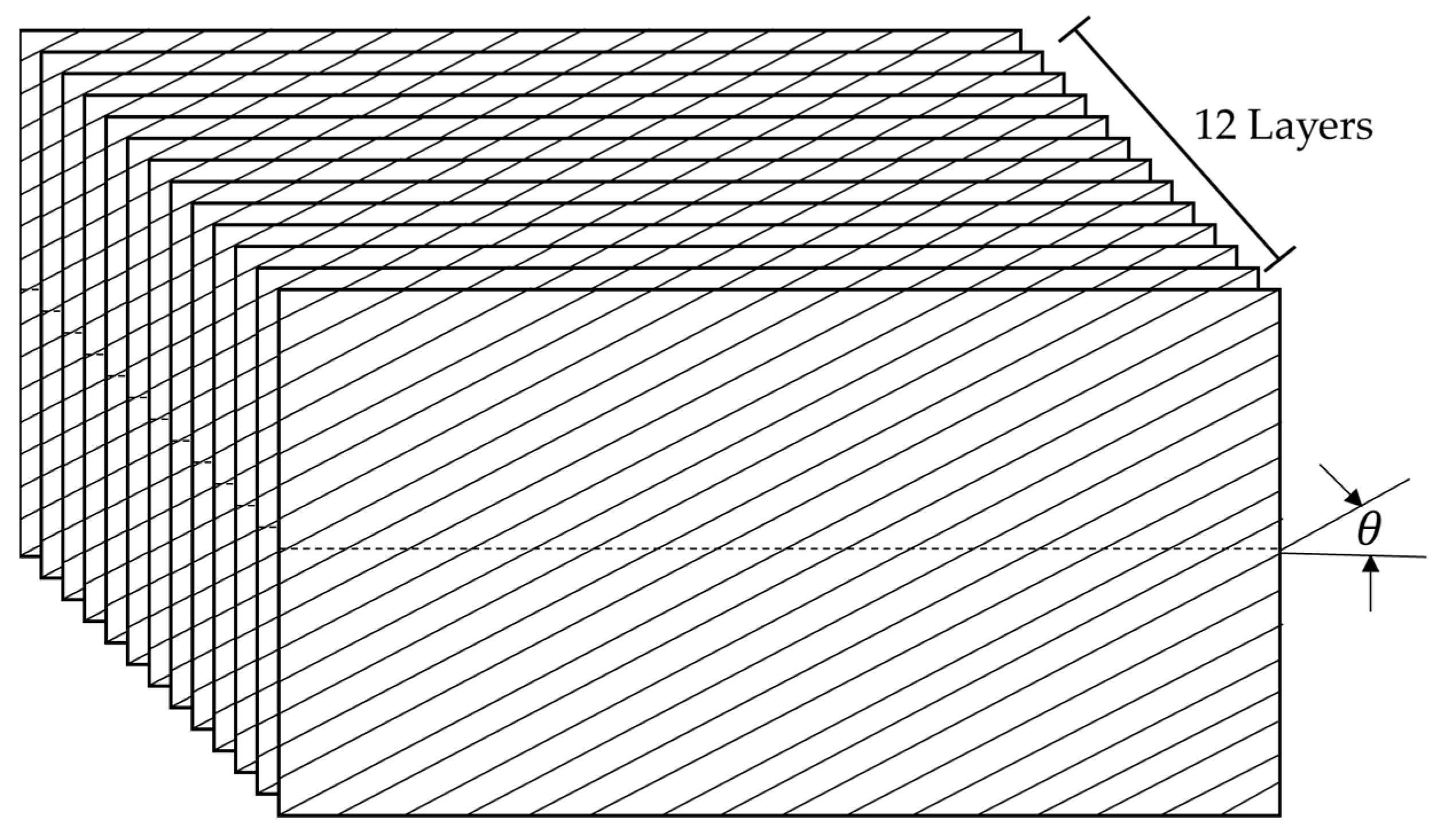
The proposed sensitivity indices require modal parameters obtained from CFRP specimens with different carbon fiber angles. The CFRP specimen was designed as a simple rectangular shape with dimensions of 80 mm (W) × 150 mm (L) × 3 mm (H) with a certain carbon fiber angle , as illustrated in Figure 1. A large composite plate was prepared from 12 layers of pre-implemented USN 250A (SK Chemical, Seongnam, Republic of Korea) and manufactured using an autoclave curing process (125 °C maximum temperature). The small-scale CFRP specimens were cut from a large CFRP plate at five different angles: , , , , .
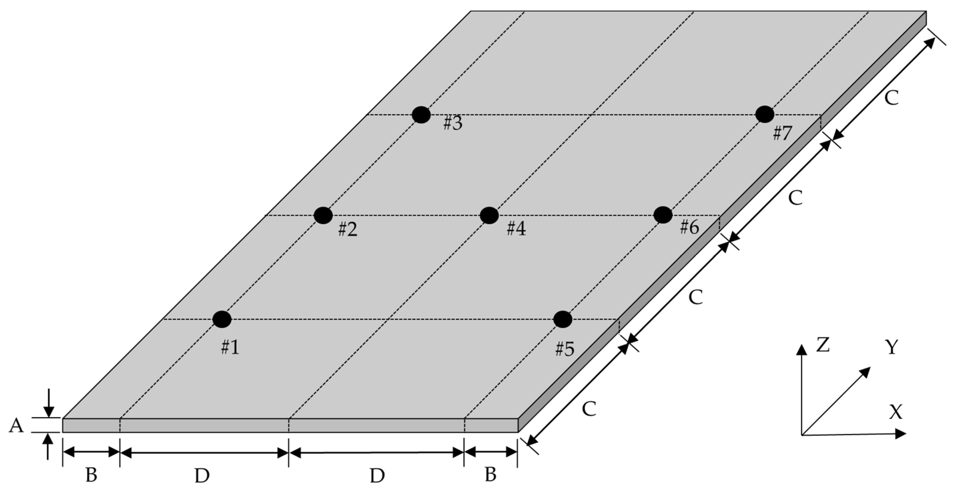
The specific configuration of the CFRP specimen is shown in Figure 2, including seven uniaxial (Z-direction) accelerometer (model: 3225F2, Dytran, Chatsworth, CA, USA) attachment locations. The mass loading effect from the attachment of seven accelerometers can be neglected because the total weight of accelerometers (1(g) × 7 = 7(g)) is much smaller than the weight of CFRP specimen, 56.5 g [24]. The sensor locations were selected to identify the dynamic behavior of the CFRP specimen by distributing them in an evenly spaced manner.
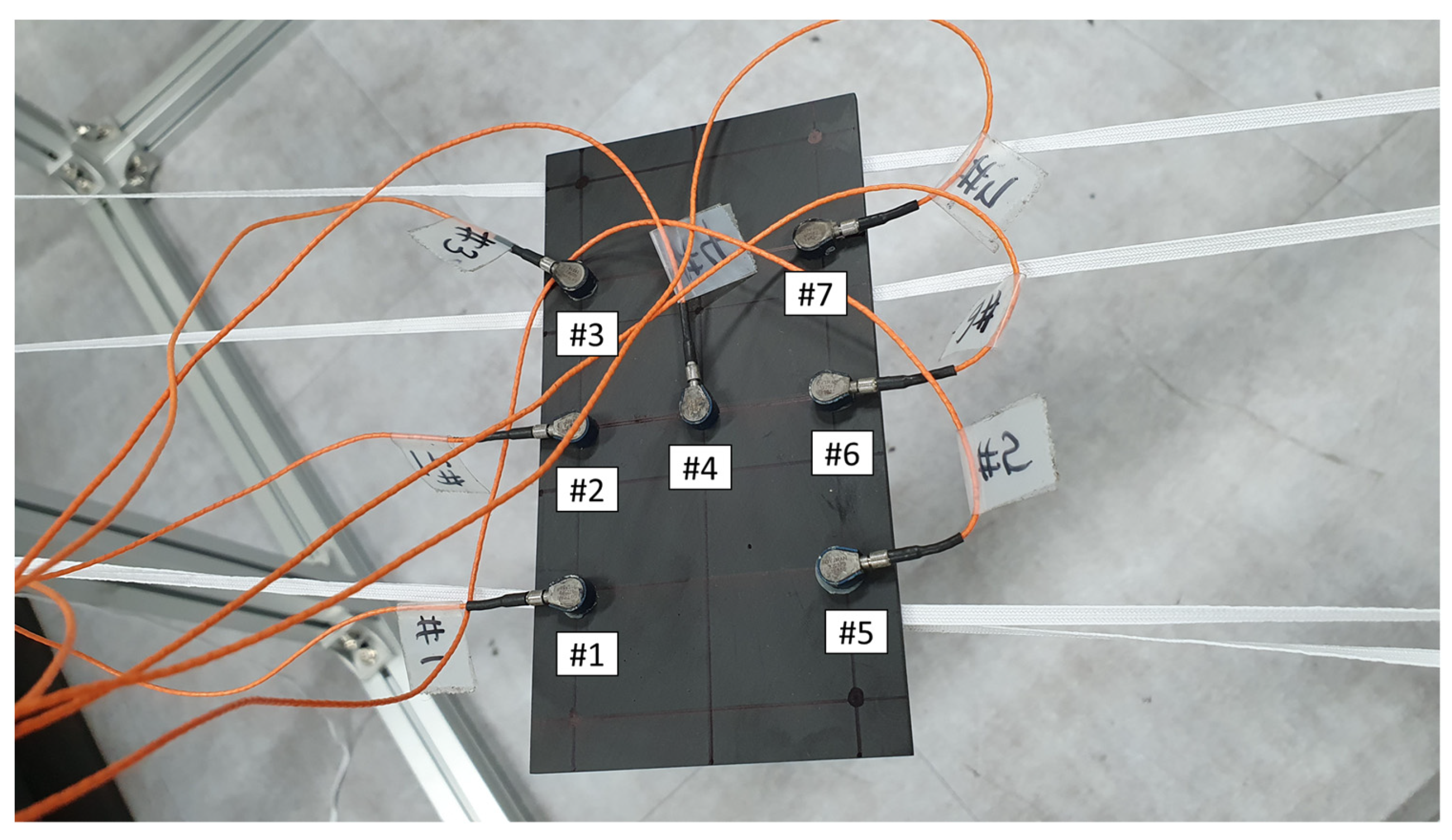
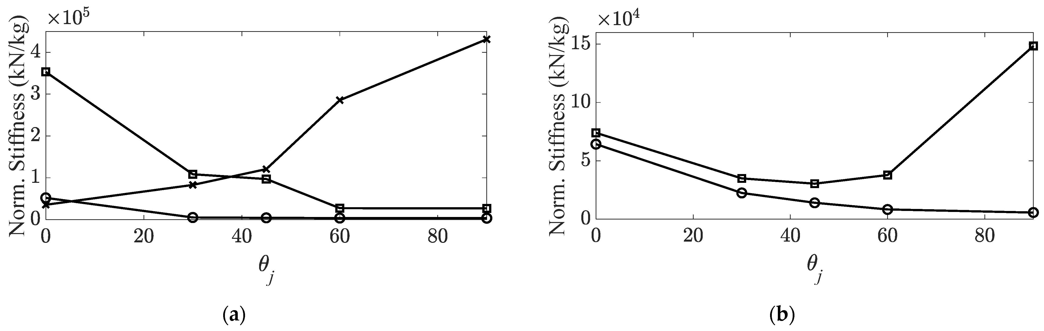
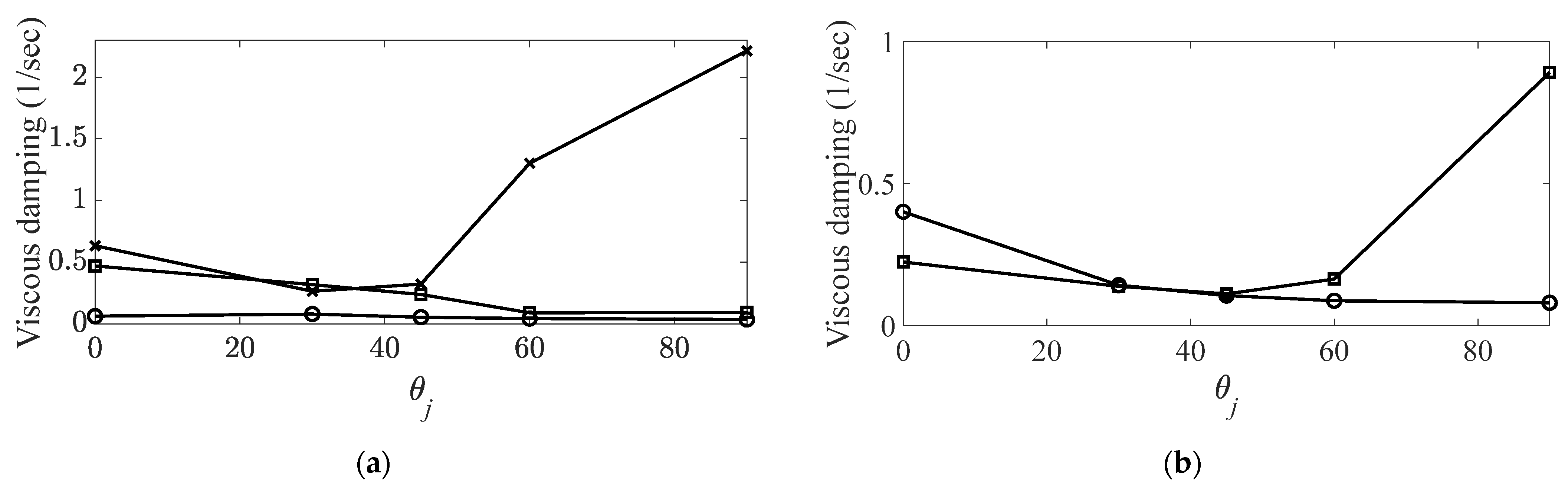
The modal parameters were identified using experimental modal testing with an impact hammer under the free-free boundary conditions of the CFRP specimens. The free-free boundary condition can be obtained by laying the CFRP specimen on a rubber band, whose stiffness is low enough to be neglected when compared to the structural stiffness of the CFRP specimens. The tested CFRP specimen suspended with a rubber band is shown in Figure 3. The frequency band of interest was selected to be between 10 Hz and 4096 Hz, and all frequency response functions (FRFs) were recorded as averaged one from ten times of measured data. The impact location was set to #4. The modal parameters of the CFRP specimens were calculated from the measured FRFs for all five carbon fiber angles. The modal parameters were verified in previous studies [23,24] for the first five modes (three bending modes and two twisting modes) and were used in this study, as summarized in Table 1. The mode tracking for the five modes of interest was conducted for CFRR specimens by three indicators, the MAC value, the variation of resonance frequency and the variation of viscous modal coefficient in the previous study [23]. The corresponding structural stiffness and viscous damping coefficient are plotted in Figure 4 and Figure 5, respectively. It can be observed that the variation in the structural stiffness seems to be similar to that of the viscous damping coefficient for all modes of interest, except for the third bending mode. As the carbon fiber angle increases, the variations of resonance frequency for the first two bending modes and the first twisting mode decrease, and that of resonance frequency for the second twisting mode decreases until and then increases up to . The variation of the viscous damping coefficient for the corresponding four modes showed similar trends as increasing the carbon fiber angle. On the other hand, the structural stiffness increases constantly but the viscous damping coefficient decreases until and then increases up to for third bending mode.
4. Relationship between Structural Stiffness and Viscous Damping Coefficient
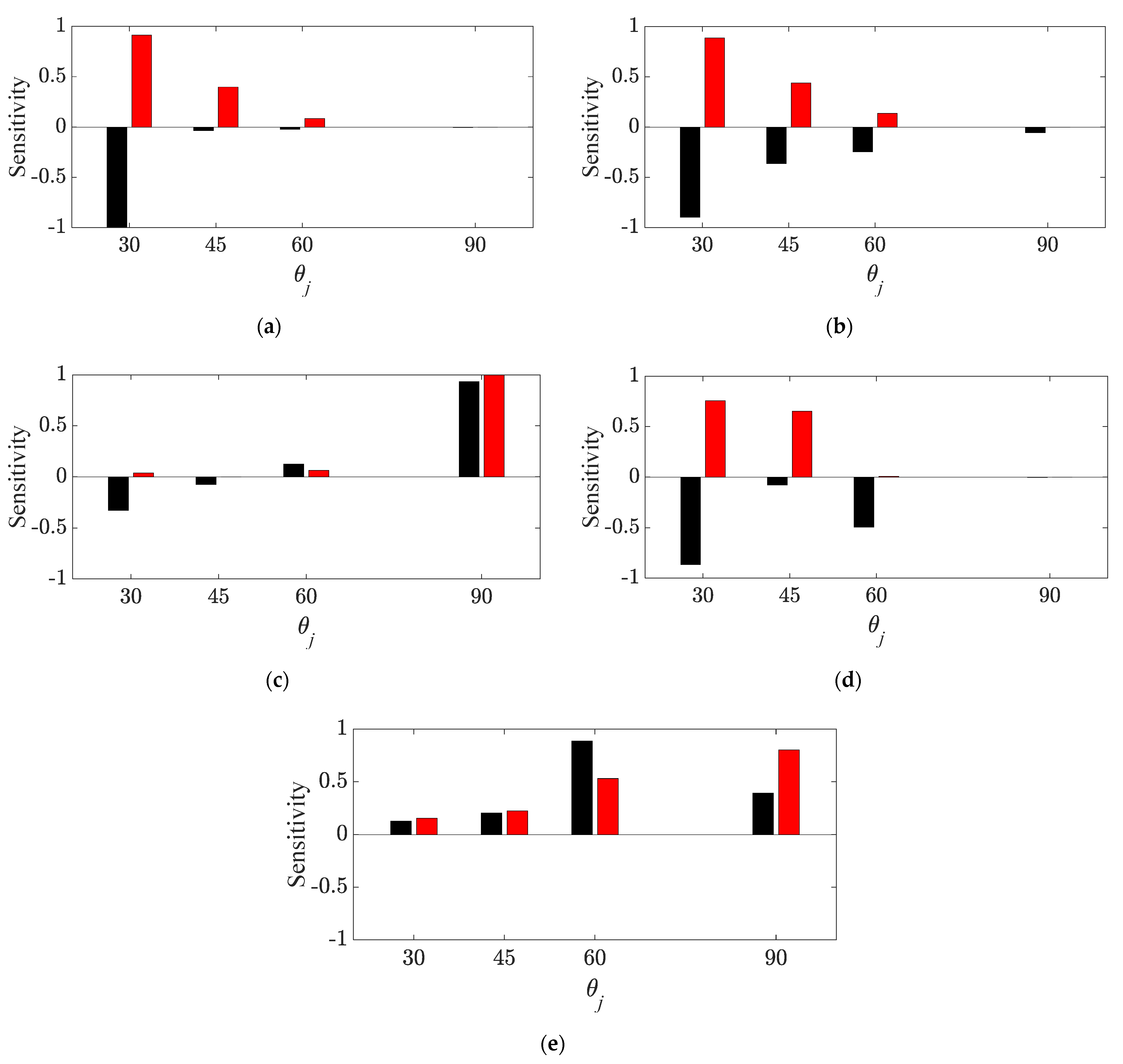
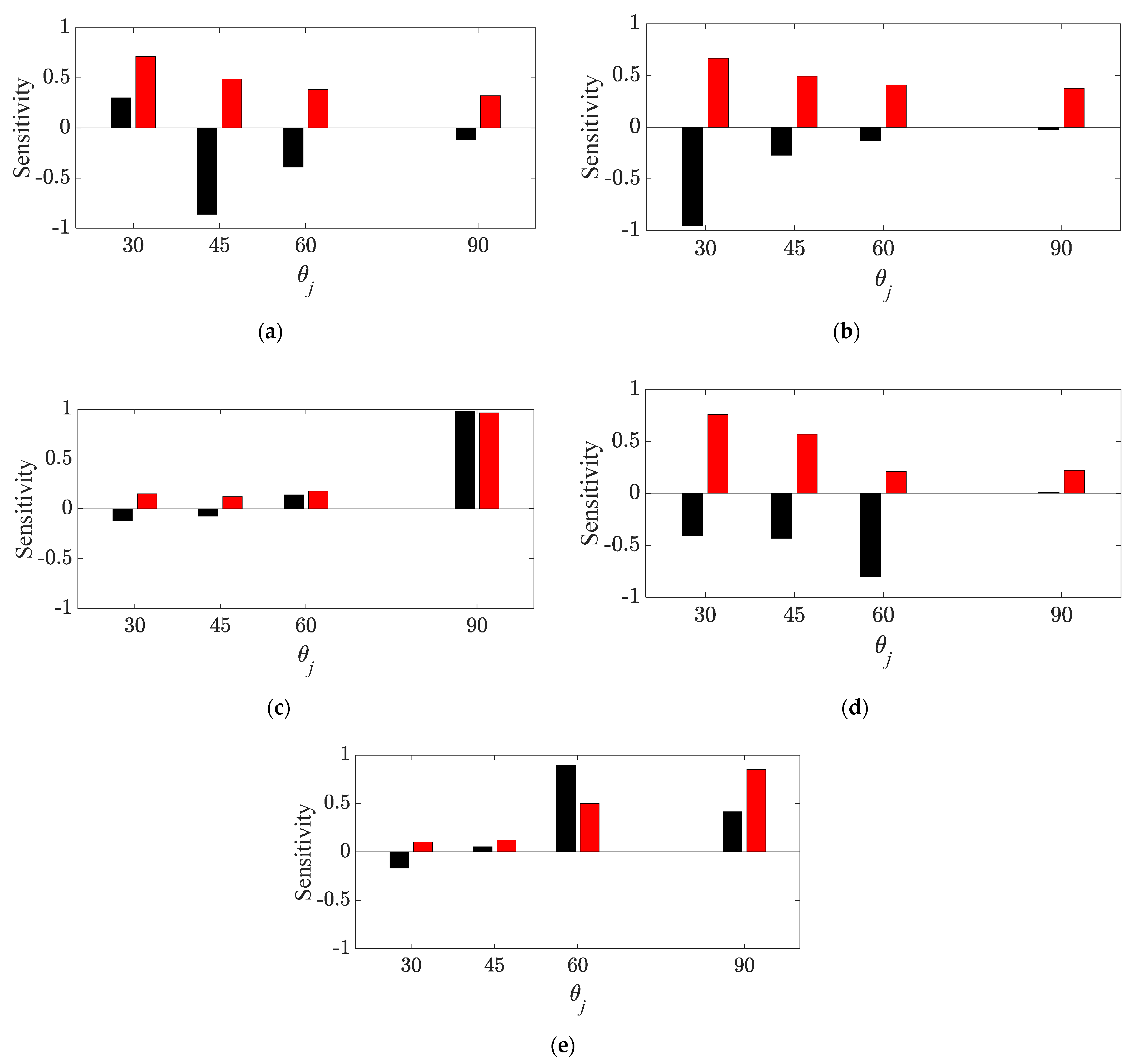
The direct variation of both equivalent parameters—structural stiffness and viscous damping coefficient—can be analyzed with sensitivity indices in Equations (21) and (22), respectively, and the variation of both parameters relating to the carbon fiber only can be analyzed with the proposed sensitivity indices in Equations (23) and (24), respectively. The measured modal parameters summarized in Table 1 were used to calculate the sensitivity indices, and the sensitivity results for each parameter are illustrated in Figure 6 and Figure 7, respectively.
The sensitivity indices for the structural stiffness show different trends for the two different parameters: the equivalent stiffness and the partial stiffness from the carbon fiber. The sensitivity of the equivalent structural stiffness in Equation (21) is used to compare the variation in structural stiffness between and . However, the proposed sensitivity formula in Equation (23) is the comparison of stiffness between and (reference angle). Accordingly, the difference between the two results of the sensitivity index in Figure 6 may be reasonable. However, both sensitivity indices regarding the structural stiffness have similar objectives by focusing only on the variation of the structural stiffness of the carbon fiber. Because the partial stiffness from the binding matrix is assumed to be constant in the equivalent structural stiffness, the variation in the equivalent structural stiffness may be highly related to the stiffness of the carbon fiber. The sensitivity index of the equivalent structural stiffness is effective for determining the variation in the structural stiffness of the CFRP specimen with respect to the variation in the carbon fiber angle.
Meanwhile, the sensitivity index of the carbon fiber is useful for determining the variation in the stiffness of the carbon fiber compared to the stiffness from the reference fiber angle, and the effect of stiffness from a binding matrix is eliminated during the derivation of the responsible sensitivity in Equation (23). The first two bending modes and first twisting mode decrease with the increasing carbon fiber angle. All sensitivity indices of the equivalent structural stiffness are negative, and the absolute value decreases from the reference carbon fiber angle (=). All sensitivity indices of the structural stiffness ratio are all positive and decrease from the reference carbon fiber angle (=). Furthermore, the third bending mode increases with the increasing carbon fiber angle; the two sensitivity indices are all positive. They generally increase for the equivalent structural stiffness but gradually increase for the stiffness ratio of carbon fiber only. In the second twisting mode, the resonance frequency decreases from to and then increases up to ; the sensitivity index of the equivalent structural stiffness starts from a negative value and decreases up to . It then becomes positive and increases up to ; the sensitivity index of the stiffness ratio of the carbon fiber is all positive and its value decreases up to and then increases rapidly to .
The explanation of the difference in the sensitivity indices in Figure 7 can be possible for reasons similar to those in the structural stiffness case. The sensitivity index of the equivalent viscous damping coefficient in Equation (22) is the calculation of variations in the damping coefficient between and and the damping coefficient ratio in Equation (24) is the variation in the damping ratio between and (reference angle). Therefore, the sensitivity indices in both cases, i.e., the equivalent viscous damping coefficient and the damping coefficient of the carbon fiber, show different results, which is also reasonable. The variations in the viscous damping coefficients show a similar trend; however, they become more complex as the carbon fiber angle increases. The viscous damping coefficients generally decrease for the first two bending modes and first twisting mode. The third bending mode also generally increases in a trend opposite to those of the previous three modes. The damping coefficient in the second twisting mode starts to decrease up to and then increases up to . Some exceptions can be found for the bending modes in Figure 5, such that the sensitivity indices of the equivalent damping coefficient shows inconsistencies at local points: the first bending mode (from to ), the second bending mode (from to ), and the third bending mode (from to ). However, the proposed sensitivity index in Equation (24) minimizes the effect of the damping coefficient of the binding matrix so that the sensitivity result from the damping ratio shows consistency in all modes of interest; the sensitivity index decreases for three modes, the first two bending modes and the first twisting mode. The sensitivity index increases for the third bending mode, and the sensitivity decreases up to and then increases up to .
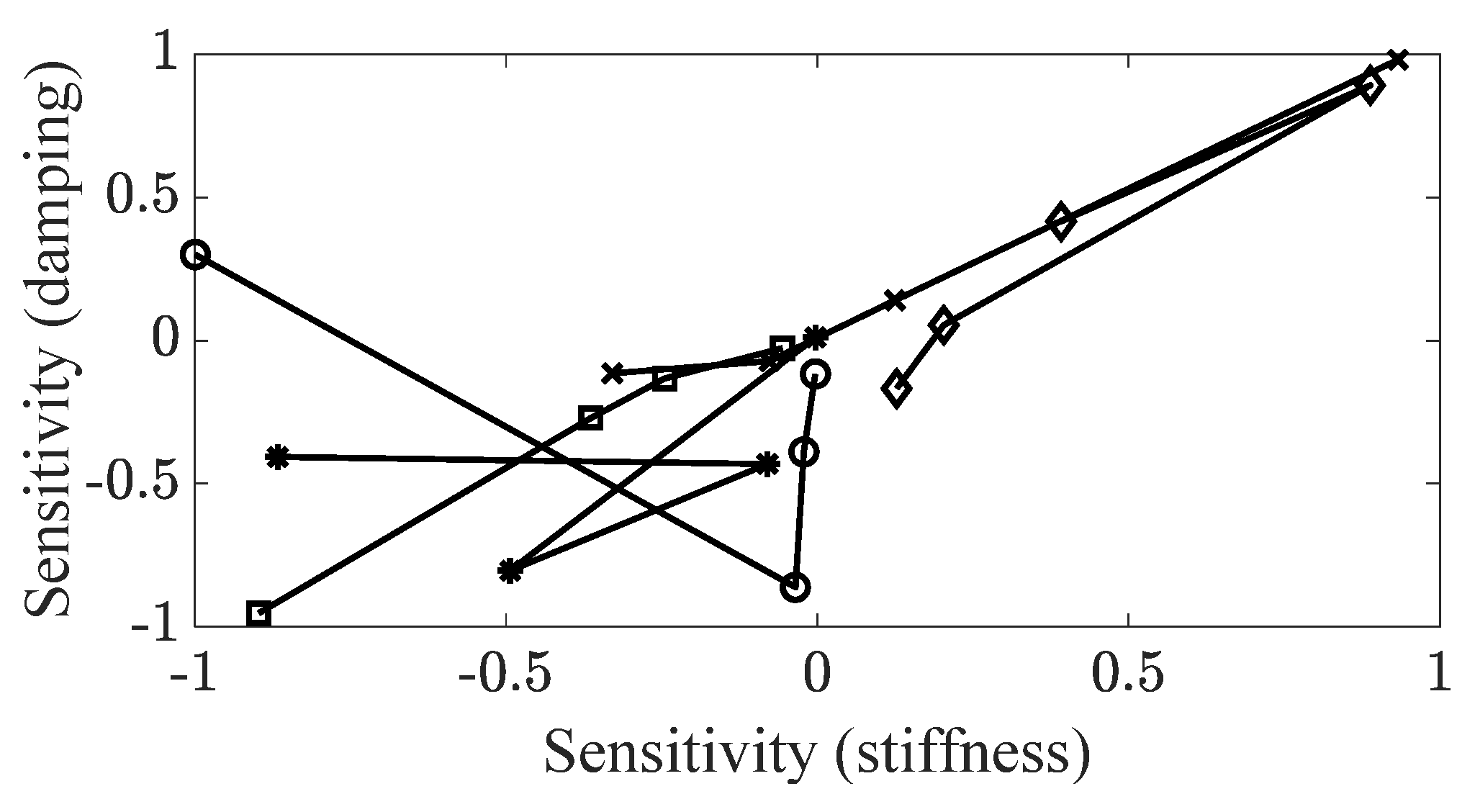
The two types of sensitivity indices for the structural stiffness and viscous damping coefficient are compared in the same graph to determine the relationship between the structural stiffness and viscous damping coefficient. The sensitivity indices of the equivalent parameters are plotted in Figure 8, and the sensitivity indices for the partial parameters of the carbon fiber are plotted in Figure 9. All sensitivity indices regarding the structural stiffness are assigned to the x-axis; all sensitivity indices regarding the viscous damping coefficient are set to the y-axis. In Figure 8, the general trend of the sensitivity index between the equivalent stiffness and equivalent damping coefficient is apparently proportional; however, some points are omitted from the linear relationship. On the other hand, the sensitivity index relationship between the stiffness of the carbon fiber and the damping coefficient of the carbon fiber is proportional for all modes of interest. The slope of each mode is not similar; it may be dependent on the variation in the resonance frequencies in Table 1. The nonlinearity observed in Figure 8 is caused by the irregularity of the rate of variations in the resonance frequency or the viscous damping coefficient over the variation in the carbon fiber angle. However, the variation in the ratio of the two parameters, both the frequency resonance frequency and the viscous damping coefficient, show a consistent trend in each mode: an increase for the first two bending modes and first twisting mode, a decrease for the third bending mode up to , and then an increase up to for the second twisting mode.
The variation in the structural stiffness of the carbon fiber may be dominant for the equivalent structural stiffness. Accordingly, the sensitivity index from the structural stiffness is reasonably changed by varying the carbon fiber angle. The maximum structural condition is given by the unique mode shape in each mode, and the increase or decrease of each mode can be clearly explained. In the case of the viscous damping coefficient, the effect of the damping coefficient of the carbon fiber remains dominant, even when compared to the damping coefficient of the binding matrix owing to the assumed parallel combination of the equivalent damping coefficient of the CFRP structure. Therefore, the proposed sensitivity indices show similar sensitivity trends according to the increase in the carbon fiber angle, which may lead to a proportional relationship between them.
It may be useful for design guidelines of CFRP structures that the change in structural stiffness is proportional to the variation in the viscous damping coefficient. When the dynamic characteristics of the CFRP structure can be identified at the reference carbon fiber angle, changes in structural stiffness at certain mode can be easily predicted from the responsible mode shape. As follows, the variation in the viscous damping coefficient of a carbon fiber can be expected due to the proportional relationship with the structural stiffness of a carbon fiber. In particular, since the equivalent viscous damping coefficient of the CFRP structure is subjective to the viscous damping coefficient of a carbon fiber as shown in Equation (20), the variation of equivalent viscous damping coefficient of CFRP structure can be predicted directly from the observation of variations in structural stiffness.
5. Conclusions
The variation in the structural stiffness was compared with the variation in the viscous damping coefficient in a CFRP structure with an increase in the carbon fiber angle. Because the variation from the binding matrix was very small compared with that from a carbon fiber in the CFRP structure, the proposed sensitivity index dealt with the ratio of both parameters—the structural stiffness, and the viscous damping coefficient—without considering the parameters of the binding matrix. An evaluation of dynamic variation in the CFRP structure was conducted for two sensitivity formulas: the first was the direct derivative of the equivalent parameters and the second was the ratio of the concerned parameters of the carbon fiber only. A sensitivity analysis was conducted with the measured modal parameters from a previous study, and the relationship between the structural stiffness and the viscous damping coefficient was evaluated. The sensitivity index of the structural stiffness of the carbon fiber was proportional to that of the viscous damping coefficient of the carbon fiber, and the linearity was slightly degraded for the sensitivity indices of the equivalent parameters. In particular, the sensitivity of the viscous damping coefficient was highly affected by the equivalent damping coefficient of the CFRP structure owing to the parallel combination of the equivalent damping coefficient. Two comparisons of the relationship between the structural stiffness and the viscous damping coefficient revealed the novelty of the proposed sensitivity index for evaluating the variation in the dynamic characteristics of the CFRP structure.
Funding
This research received no external funding.
Institutional Review Board Statement
Not applicable.
Informed Consent Statement
Not applicable.
Data Availability Statement
The data presented in this study are available on request from the corresponding author.
Acknowledgments
This work was supported by the National Research Foundation of Korea (Grant No. 2020R1F1A104860211).
Conflicts of Interest
The authors declare no conflict of interest.
Nomenclature
| mass of 1-DOF (degree-of-freedom) system | |
| modal mass at ith mode of multi-DOF system | |
| stiffness coefficient at 1-DOF system | |
| stiffness coefficient of a carbon fiber at 1-DOF system | |
| stiffness coefficient of a binding matrix at 1-DOF system | |
| equivalent stiffness coefficient at 1-DOF system | |
| ith mass-normalized structural stiffness of a carbon fiber at multi-DOFs system, carbon fiber angle | |
| ith mass-normalized structural stiffness of a binding matrix at multi-DOFs system, carbon fiber angle | |
| ith mass-normalized equivalent structural stiffness at multi-DOFs system, carbon fiber angle | |
| modal damping ratio at 1-DOF system | |
| ith modal damping ratio at multi-DOFs system | |
| ith modal damping ratio of a carbon fiber at multi-DOFs system | |
| ith modal damping ratio of a binding matrix at multi-DOFs system | |
| viscous damping coefficient at 1-DOF system | |
| viscous damping coefficient of a carbon fiber at 1-DOF system | |
| viscous damping coefficient of a binding matrix at 1-DOF system | |
| equivalent viscous damping coefficient at 1-DOF system | |
| ith mass-normalized viscous damping coefficient of a carbon fiber at multi-DOFs system, carbon fiber angle | |
| ith mass-normalized viscous damping coefficient of a binding matrix at multi-DOFs system, carbon fiber angle | |
| ith mass-normalized equivalent viscous damping coefficient at multi-DOFs system, carbon fiber angle | |
| resonance frequency at 1-DOF system | |
| resonance frequency at ith mode of multi-DOF system | |
| resonance frequency of a carbon fiber at 1-DOF system | |
| resonance frequency of a binding matrix at 1-DOF system | |
| ith resonance frequency of a carbon fiber at multi-DOFs system, carbon fiber angle | |
| ith resonance frequency of a binding matrix at multi-DOFs system, carbon fiber angle | |
| carbon fiber angle | |
| jth carbon fiber angle ( reference angle) | |
| number of times a carbon fiber increases | |
| derivative variable | |
| averaged modal damping ratio between the (j−1)th carbon angle and jth carbon angle | |
| averaged resonance frequency between the (j−1)th carbon angle and jth carbon angle | |
| sensitivity index based on the partial derivatives of the mass-normalized equivalent structural stiffness over at ith mode | |
| sensitivity index based on the partial derivatives of the mass-normalized viscous damping coefficient over at ith mode | |
| sensitivity index based on the structural stiffness of a carbon fiber at ith mode, the carbon fiber angle | |
| sensitivity index based on the viscous damping coefficient of a carbon fiber at ith mode, the carbon fiber angle |
References
- Chawla, K.K. Composite Materials—Science and Engineering, 1st ed.; Springer: Tokyo, Japan, 1987; pp. 150–163. [Google Scholar]
- Courtney, T.H. Mechanical Behavior of Materials, 2nd ed.; McGraw-Hill: Singapore, 2000; pp. 244–292. [Google Scholar]
- Beer, F.; Johnston, E.R. Mechanics of Materials, 7th ed.; McGraw-Hill: New York, NY, USA, 2015; pp. 104–108. [Google Scholar]
- Ma, Y.; Xin, C.; Zhang, W.; Jin, G. Experimental study of plasma plume analysis of long pulse laser irradiates CFRP and GFRP composite materials. Crystals 2021, 11, 545. [Google Scholar] [CrossRef]
- An, D.; Lotfian, S.; Mesbah, D.; Ayre, D.; Yoosefinejad, A.; Thakur, V.K.; Yazdani Nezhad, H. Ultra-thin electrospun nanofibers for development of damage-tolerant composite laminates. Crystals 2019, 14, 100202. [Google Scholar] [CrossRef]
- Micelli, F.; Cascardi, A.; Aiello, M.A. Pre-load effect on CFRP-comfinement of concrete columns: Experimental and theoretical study. Crystals 2021, 11, 177. [Google Scholar] [CrossRef]
- Zhao, H.; Kong, X.; Fu, Y.; Gu, Y.; Wang, X. Numerical investigation on dynamic response of RC T-beams strengthened with CFRP under impact loading. Crystals 2020, 11, 890. [Google Scholar] [CrossRef]
- Patangtalo, W.; Hyer, M.W.; Aimmanee, S. On the non-axisymmetric behavior of quasi-isotropic woven fiber-reinforced composite Belleville springs. J. Reinf. Plast. Compos. 2016, 35, 334. [Google Scholar] [CrossRef]
- Khalid, M.Y.; Rashid, A.A.; Arif, Z.U.; Akram, N.; Arshad, H.; Marquez, F.P.G. Characterization of failure strain in fiber reinforced composites: Under on-axis and off-axis loading. Crystals 2021, 11, 216. [Google Scholar] [CrossRef]
- Dannemann, M.; Holeczek, K.; Leimert, J.; Friebe, S.; Modler, N. Adaptive measuring sequence for the determination of directional-dependent dynamic material properties using bending resonance method. Polym. Test. 2019, 79, 106044. [Google Scholar] [CrossRef]
- Mahmoudi, S.; Kervoelen, A.; Robin, G.; Duigou, L.; Daya, E.M.; Cadou, J.M. Experimental and numerical investigation of the damping of flax-epoxy composite plates. Compos. Struct. 2019, 208, 426–433. [Google Scholar] [CrossRef]
- Sol, H.; Rahier, H.; Gu, J. Prediction and measurement of the damping ratios of laminated polymer composite plates. Materials 2020, 13, 3370. [Google Scholar] [CrossRef] [PubMed]
- Dannemann, M.; Siwek, S.; Modler, N.; Wagenfuhr, A.; Tietze, J. Damping behavior of thermoplastic organic sheets with continuous natural fiber-reinforcement. Vibrations 2021, 4, 529–536. [Google Scholar] [CrossRef]
- Ewins, D.J. Modal Testing, 3rd ed.; Research Studies Press Ltd.: Hertfordshire, UK, 2000. [Google Scholar]
- Inman, D.J. Engineering Vibration, 4th ed.; Pearson: Singapore, 2013. [Google Scholar]
- Rao, S.S. Mechanical Vibration, 5th ed.; Pearson: Singapore, 2011. [Google Scholar]
- Larsson, D. Using modal analysis for estimation of anisotropic material constants. J. Eng. Mech. 1997, 123, 222–229. [Google Scholar] [CrossRef]
- Albuquerque, E.L.; Sollero, P.; Fedelinski, P. Free vibration analysis of anisotropic material structures using the boundary element method. Eng. Anal. Bound. Elem. 2003, 27, 977–985. [Google Scholar] [CrossRef]
- Mota, G.M.; Sollero, P.; Batista, F.B.; Albuquerque, E.L. Modal analysis technique for isotropic composite laminates. In Proceedings of the 2008 International Conference on Computer Engineering & Systems, Cairo, Egypt, 25–27 November 2008; Volume 7, pp. 95–100. [Google Scholar]
- Kang, H.Y.; Kim, C.J.; Lee, J. Viscous damping coefficient estimation of carbon-fiber reinforced plastic material considering temperature condition. Materials 2020, 13, 2872. [Google Scholar] [CrossRef] [PubMed]
- Kim, C.J. Temperature-dependent dynamic characteristics of carbon-fiber-reinforced plastic for different spectral loading patterns. Materials 2020, 13, 5238. [Google Scholar] [CrossRef] [PubMed]
- Kim, C.J. Comparison of mode shapes of carbon-fiber-reinforced plastic material considering carbon fiber direction. Crystals 2021, 11, 311. [Google Scholar] [CrossRef]
- Kim, C.J. Modal parameter tracking in carbon-fiber reinforced structure over different carbon fiber angle. J. Mar. Sci. Eng. 2021. submitted. [Google Scholar]
- Kim, C.J. Sensitivity of the viscous damping coefficient of carbon fiber in carbon-fiber-reinforced plastic with respect to the fiber angle. Crystals 2021, 11, 781. [Google Scholar] [CrossRef]
Figure 1.
Carbon fiber angle in the multi-layered CFRP specimen.

Figure 2.
Configuration of simple rectangular specimen and sensor attachment locations: A: 3 mm, B: 10 mm, C: 37.5 mm, D: 30 mm [22,23].


Figure 4.
Variations in structural stiffness according to carbon fiber angle: (a) ![Crystals 11 01252 i001]() : first bending mode,
: first bending mode, ![Crystals 11 01252 i002]() : second bending mode,
: second bending mode, ![Crystals 11 01252 i003]() : third bending mode; (b)
: third bending mode; (b) ![Crystals 11 01252 i001]() : first twisting mode,
: first twisting mode, ![Crystals 11 01252 i002]() : second twisting mode.
: second twisting mode.
 : first bending mode,
  : second bending mode,
  : third bending mode; (b) : first twisting mode, : second twisting mode.
Figure 4.
Variations in structural stiffness according to carbon fiber angle: (a) ![Crystals 11 01252 i001]() : first bending mode,
: first bending mode, ![Crystals 11 01252 i002]() : second bending mode,
: second bending mode, ![Crystals 11 01252 i003]() : third bending mode; (b)
: third bending mode; (b) ![Crystals 11 01252 i001]() : first twisting mode,
: first twisting mode, ![Crystals 11 01252 i002]() : second twisting mode.
: second twisting mode.
: first bending mode, : second bending mode, : third bending mode; (b) : first twisting mode, : second twisting mode.
Figure 5.
Variations in viscous damping coefficient according to carbon fiber angle: (a) ![Crystals 11 01252 i001]() : first bending mode,
: first bending mode, ![Crystals 11 01252 i002]() : second bending mode,
: second bending mode, ![Crystals 11 01252 i003]() : third mode; (b)
: third mode; (b) ![Crystals 11 01252 i001]() : first twisting mode,
: first twisting mode, ![Crystals 11 01252 i002]() : second twisting mode.
: second twisting mode.
: first bending mode, : second bending mode, : third mode; (b) : first twisting mode, : second twisting mode.
Figure 6.
Sensitivity analysis results, ![Crystals 11 01252 i004]() : the mass-normalized equivalent structural stiffness,
: the mass-normalized equivalent structural stiffness, ![Crystals 11 01252 i005]() : the structural stiffness ratio between the carbon fiber angle and the reference one. (a) First mode (first bending); (b) second mode; (first twisting); (c) third mode (second twisting); (d) fourth mode (second bending); (e) fifth mode (third bending).
: the structural stiffness ratio between the carbon fiber angle and the reference one. (a) First mode (first bending); (b) second mode; (first twisting); (c) third mode (second twisting); (d) fourth mode (second bending); (e) fifth mode (third bending).
 : the mass-normalized equivalent structural stiffness,
  : the structural stiffness ratio between the carbon fiber angle and the reference one. (a) First mode (first bending); (b) second mode; (first twisting); (c) third mode (second twisting); (d) fourth mode (second bending); (e) fifth mode (third bending).
Figure 6.
Sensitivity analysis results, ![Crystals 11 01252 i004]() : the mass-normalized equivalent structural stiffness,
: the mass-normalized equivalent structural stiffness, ![Crystals 11 01252 i005]() : the structural stiffness ratio between the carbon fiber angle and the reference one. (a) First mode (first bending); (b) second mode; (first twisting); (c) third mode (second twisting); (d) fourth mode (second bending); (e) fifth mode (third bending).
: the structural stiffness ratio between the carbon fiber angle and the reference one. (a) First mode (first bending); (b) second mode; (first twisting); (c) third mode (second twisting); (d) fourth mode (second bending); (e) fifth mode (third bending).
: the mass-normalized equivalent structural stiffness, : the structural stiffness ratio between the carbon fiber angle and the reference one. (a) First mode (first bending); (b) second mode; (first twisting); (c) third mode (second twisting); (d) fourth mode (second bending); (e) fifth mode (third bending).
Figure 7.
Sensitivity analysis results, ![Crystals 11 01252 i004]() : the mass-normalized equivalent viscous damping coefficient,
: the mass-normalized equivalent viscous damping coefficient, ![Crystals 11 01252 i005]() : the viscous damping coefficient ratio between the carbon fiber angle and the reference one. (a) First mode (first bending); (b) second mode (first twisting); (c) third mode (second twisting); (d) fourth mode (second bending); (e) fifth mode (third bending).
: the viscous damping coefficient ratio between the carbon fiber angle and the reference one. (a) First mode (first bending); (b) second mode (first twisting); (c) third mode (second twisting); (d) fourth mode (second bending); (e) fifth mode (third bending).
: the mass-normalized equivalent viscous damping coefficient, : the viscous damping coefficient ratio between the carbon fiber angle and the reference one. (a) First mode (first bending); (b) second mode (first twisting); (c) third mode (second twisting); (d) fourth mode (second bending); (e) fifth mode (third bending).
Figure 8.
Sensitivity index comparison of equivalent parameters between the structural stiffness and the viscous damping coefficient: ![Crystals 11 01252 i001]() : first bending mode,
: first bending mode, ![Crystals 11 01252 i002]() : first twisting mode,
: first twisting mode, ![Crystals 11 01252 i003]() : second twisting mode,
: second twisting mode, ![Crystals 11 01252 i006]() : second bending mode,
: second bending mode, ![Crystals 11 01252 i007]() : third bending mode.
: third bending mode.
: first bending mode, : first twisting mode, : second twisting mode,  : second bending mode,
  : third bending mode.
Figure 8.
Sensitivity index comparison of equivalent parameters between the structural stiffness and the viscous damping coefficient: ![Crystals 11 01252 i001]() : first bending mode,
: first bending mode, ![Crystals 11 01252 i002]() : first twisting mode,
: first twisting mode, ![Crystals 11 01252 i003]() : second twisting mode,
: second twisting mode, ![Crystals 11 01252 i006]() : second bending mode,
: second bending mode, ![Crystals 11 01252 i007]() : third bending mode.
: third bending mode.
: first bending mode, : first twisting mode, : second twisting mode, : second bending mode, : third bending mode.
Figure 9.
Sensitivity index comparison of parameters of the carbon fiber between the structural stiffness and the viscous damping coefficient: ![Crystals 11 01252 i001]() : first bending mode,
: first bending mode, ![Crystals 11 01252 i002]() : first twisting mode,
: first twisting mode, ![Crystals 11 01252 i003]() : second twisting mode,
: second twisting mode, ![Crystals 11 01252 i006]() : second bending mode,
: second bending mode, ![Crystals 11 01252 i007]() : third bending mode.
: third bending mode.
: first bending mode, : first twisting mode, : second twisting mode, : second bending mode, : third bending mode.

Table 1.
Measured modal parameters of the CFRP specimen for five different carbon fiber angles [23,24].
| Specimen | Resonance Frequency (Hz) | Modal Damping Ratio (%) | Mode Shape |
|---|---|---|---|
| CFRP specimen #1 ( | 1149.1 | 0.4 | Bending (first) |
| 1276.1 | 2.5 | Twisting (first) | |
| 1368.7 | 1.3 | Twisting (second) | |
| 2990.9 | 1.3 | Bending (second) | |
| 951.0 | 5.3 | Bending (third) | |
| CFRP specimen #2 ( | 360.6 | 0.39 | Bending (first) |
| 754.5 | 0.21 | Twisting (first) | |
| 941.1 | 0.82 | Twisting (second) | |
| 1657.6 | 0.01 | Bending (second) | |
| 1450.4 | 0.55 | Bending (third) | |
| CFRP specimen #3 ( | 330.4 | 1.3 | Bending (first) |
| 595.6 | 1.4 | Twisting (first) | |
| 878.0 | 1.0 | Twisting (second) | |
| 1568.9 | 1.2 | Bending (second) | |
| 1749.2 | 1.5 | Bending (third) | |
| CFRP specimen #4 ( | 310.6 | 1.1 | Bending (first) |
| 458.5 | 1.5 | Twisting (first) | |
| 979.0 | 1.3 | Twisting (second) | |
| 835.0 | 0.9 | Bending (second) | |
| 2690.4 | 3.9 | Bending (third) | |
| CFRP specimen #5 ( | 305.1 | 0.9 | Bending (first) |
| 380.0 | 1.7 | Twisting (first) | |
| 1938.5 | 3.7 | Twisting (second) | |
| 824.1 | 0.9 | Bending (second) | |
| 3305.1 | 5.3 | Bending (third) |
Publisher’s Note: MDPI stays neutral with regard to jurisdictional claims in published maps and institutional affiliations. |
© 2021 by the author. Licensee MDPI, Basel, Switzerland. This article is an open access article distributed under the terms and conditions of the Creative Commons Attribution (CC BY) license (https://creativecommons.org/licenses/by/4.0/).
Share and Cite
MDPI and ACS Style
Kim, C.-J. Relationship between Structural Stiffness and Viscous Damping Coefficient in Reinforced Carbon Structure under Varying Carbon Fiber Angles. Crystals 2021, 11, 1252. https://0-doi-org.brum.beds.ac.uk/10.3390/cryst11101252
AMA Style
Kim C-J. Relationship between Structural Stiffness and Viscous Damping Coefficient in Reinforced Carbon Structure under Varying Carbon Fiber Angles. Crystals. 2021; 11(10):1252. https://0-doi-org.brum.beds.ac.uk/10.3390/cryst11101252
Chicago/Turabian StyleKim, Chan-Jung. 2021. "Relationship between Structural Stiffness and Viscous Damping Coefficient in Reinforced Carbon Structure under Varying Carbon Fiber Angles" Crystals 11, no. 10: 1252. https://0-doi-org.brum.beds.ac.uk/10.3390/cryst11101252
Note that from the first issue of 2016, this journal uses article numbers instead of page numbers. See further details here.