Article

Fast, Accurate and Full Extraction of Coupling-of-Modes Parameters by Finite Element Method

1
School of Optoelectronic Engineering, Xi’an Technological University, Xi’an 710021, China
2
School of Microelectronics, Xidian University, Xi’an 710071, China
3
School of Information Science and Engineering, Shandong Normal University, Jinan 250358, China
4
State Key Laboratory of Acoustics, Institute of Acoustics, Chinese Academy of Sciences, Beijing 100190, China
*
Author to whom correspondence should be addressed.
Submission received: 3 April 2022 / Revised: 10 May 2022 / Accepted: 14 May 2022 / Published: 16 May 2022
(This article belongs to the Special Issue Ferroelectric and Piezoelectric Crystals)

Abstract

:
This paper presents a new numerical approach for the full extraction of the coupling-of-modes (COM) parameters by stationary and eigenfrequency analyses in the finite element method (FEM). This is a fast method extracting from the results of static analysis and eigenfrequency analysis. It avoids the long calculation time of admittance frequency response analysis, which is commonly used in extracting COM parameters. In addition to the usual COM parameters (velocity, reflection coefficient, transduction coefficient and capacitance), the phases of reflection and transduction coefficient can be also extracted with this method. The proposed method was applied to different cutting types LiNbO3 with different types of thicknesses in a varying interdigital transducer (IDT). These examples show that our approach has great potential in extracting all the COM parameters of the Rayleigh SAW for all kinds of IDT structures. Therefore, it is a fast, accurate, general and full extraction approach of COM parameters.

1. Introduction

The design of high-performance SAW devices requires accurate and efficient simulation techniques. The complexity of modeling IDT or functional gradient materials [1,2] make it difficult to obtain a rigorous analytical solution. FEM is an effective method in designing SAW devices because it can directly describe the coupled partial differential equations involving the electric and mechanical fields in a grating consisting of a piezoelectric substrate with electrodes [3]. It can handle arbitrary materials and crystal cuts, different electrode shapes and structures including multiple metal and dielectric layers [4,5]. Compared with phenomenological models, superior performances of FEM on accuracy have been validated when considering a necessary discretization of at least 10 elements per wavelength. That is to say, the accuracy depends on the number of grids. Consequently, it is time-consuming to simulate the whole device, since a huge number of grids are necessary to improve the precision, but which require intensive computation [6,7]. Therefore, it cannot be directly used to optimize the device performance.
Compared with other phenomenological models, such as the equivalent circuit model [8], the COM model is a more efficient model in simulating and designing SAW devices. In addition to the acoustoelectric interactions of the electric current with the surface acoustic waves, the COM model considers the excitation, propagation and mutual reflection of counter-propagating waves in a continuous medium [9]. Since it is a phenomenological model, the heavy dependence of the COM model on the accurate COM parameters is evident. Many researchers have made much effort to acquire these parameters experimentally and theoretically. Hartmann et al. extracted the needed COM parameters from measurements [10,11]. However, this process is both time-consuming and expensive because of the many degrees of SAW structures, such as the relative electrode thickness, the metallization ratio and the electrode profile. Some numerical methods, such as a combination of FEM and boundary element methods [12,13], a full FEM [14] and finite element method–spectral domain analysis [15,16], have also been employed for COM parameters extraction.
Regarding to the reflection coefficient and transduction coefficient, most of researchers are got only in their absolute value. To obtain the best unidirectivity for SPUDT, one must know the accurate COM parameters, including the phases of reflection coefficient and transduction coefficient, to find out if the length between the transduction and reflection centers is 1/8 wavelength or not [17]. Hashimoto et al. used the input admittance to find the two resonances and two antiresonances to extract all the absolute values of the COM parameters except capacitance C and the phase difference between the phase of reflection coefficient and the double phase of the transduction coefficient [15,18,19]. They obtained capacitance C by the fitting methods, with the results of the input admittance calculated using the MSYNC software. However, the sign of the phase difference could not be determined. Yong’an Shui et al. used the periodic Green’s function method to extract all the COM parameters, including the phase of reflection coefficient, but not the phase of transduction coefficient [20].
In this paper, we will demonstrate an approach to extract all the COM parameters. This approach makes full use of the results of static analysis and eigenfrequency analysis obtained by the FEM. It avoids the long calculation time in the frequency response analysis. Subsequently, we will demonstrate the results of several examples of its application. These results show that this approach is powerful to fully extract the COM parameters of the Rayleigh wave for all kinds of IDT structures on arbitrary materials.

2. Theory to Extract COM Parameters
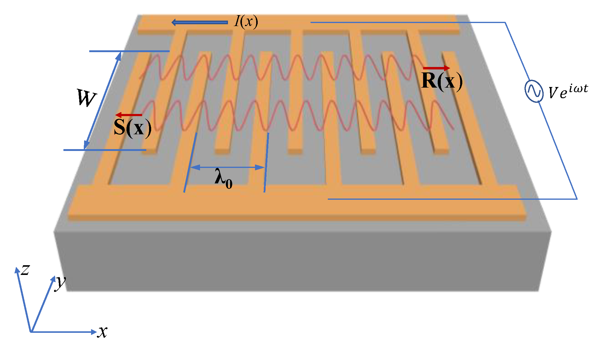
2.1. COM Model

It is assumed that there are two counter-propagating waves which exist in a grating, where one of them propagates toward the +x direction, whereas the other propagates toward the −x direction. The two waves are represented as R(x) and S(x), respectively. There are three common types of COM differential equations. These differential equations vary depending on whether the direction of the current flow is the same or opposite to the coordinate system and the sign of reflection coefficient κ. As shown in Figure 1, R(x) and S(x) represent the two counter-propagating waves, and I(x) is the current caused by the induced charges in the electrodes when the transducer is driven by a voltage V, whose direction is opposite to x. The drive voltage V and current I are defined by their half-power amplitude values.
Introducing the slow varying fields R0(x), S0(x) of R(x) and S(x):
{ R ( x ) = R 0 ( x ) exp ( i k 0 x ) S ( x ) = S 0 ( x ) exp ( i k 0 x ) ,
where k0 = 2π/λ0. Moreover, defining a detuning parameter Δ as:
Δ = k k 0 = ω v 2 π λ 0 ,
where ω is the angular frequency, ν is the velocity and λ0 is the electric period of the gratings. Then, the final COM equations can be written as [9,21]:
{ R 0 x = i Δ R 0 ( x ) + i κ S 0 ( x ) + i α V S 0 x = i κ R 0 ( x ) + i Δ S 0 ( x ) i α V I x = 2 i α R 0 ( x ) 2 i α S 0 ( x ) + i ω C V ,
where velocity ν, the reflection coefficient κ, the transduction coefficient α and the static capacitance per unit length C are the four independent COM parameters to be determined. Generally, κ and α are complex numbers.
If we define the reflection coefficient κ = −κ, the resulting COM equations are the second form, which has been widely used in Japan [18,22,23]. If we define I(x) = −I(x) and introduce the thin film resistance of an interdigital transducer, the third form COM equations would be derived. This form was also used in many papers [24,25,26].
No matter which kinds of COM model is used, all the four characteristic parameters need to be extracted. In the next section, we developed a parameters extraction technique for all four COM parameters mentioned above based on the FEM.

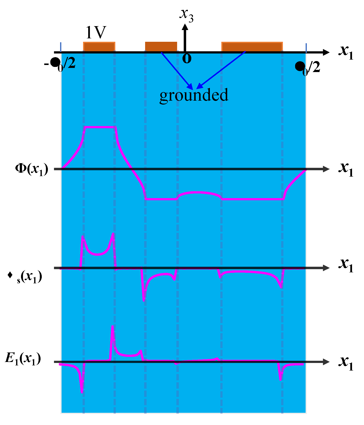
2.2. Extraction Technique of COM Parameters

The static capacitance is a measure of the electrostatic energy stored in an IDT and it can be calculated from the charge distribution and electric field distribution excited by the transducer subject to a constant voltage. When the applied voltage is 1V, the static capacitance of one period Cp is the integral of charge distribution on the electrode.
The other parameters can be extracted from the stopband characteristics of the short-circuited and open-circuited grating. For a short-circuited grating, the voltage will be set at 0V, and the COM equations will be reduced to the form [27] given in Equation (4).
{ R 0 x = i Δ R 0 ( x ) + i κ S 0 ( x ) S 0 x = i κ R 0 ( x ) + i Δ S 0 ( x ) ,
The solution is of the form in Equation (5)
{ R ( x ) = c 1 exp [ i ( k 0 q s c ) x ] + c 2 exp [ i ( k 0 + q s c ) x ] S ( x ) = 1 κ { c 1 ( Δ + q s c ) exp [ i ( k 0 + q s c ) x ] + c 2 ( Δ q s c ) exp [ i ( k 0 q s c ) x ] } ,
and satisfies the dispersion relation [18] in Equation (6):
q s c = { Δ 2 | κ | 2 ( Δ < | κ | ) i | κ | 2 Δ 2 ( Δ < | κ | ) Δ 2 | κ | 2 ( Δ > | κ | ) ,
where c1 and c2 are arbitrary coefficients of the two eigenmodes which are determined by the initial and boundary conditions. Each of them may be interpreted as combinations of an incident wave and a reflected wave. It can be seen from Equations (5) and (6) that the eigenmodes form a stopband in the frequency region, |Δ| < |κ|. Here, we use the phase φκ and amplitude |κ| to describe the reflection coefficient as κ = |κ|exp(κ). The amplitude of κ determines the width of the stopband. The lower and upper frequencies of the stopband fs+ and fs− can be obtained by considering the zeros of the dispersion relation [28,29]. Then, we have:
{ f s + = ( 1 + | κ | λ 0 2 π ) f s f s = ( 1 | κ | λ 0 2 π ) f s ,
From Equation (7), the center frequency of the short-circuited grating fs and |κ| can be represented as Equations (8) and (9).
f s = f s + + f s 2 ,
| κ | = 2 π λ 0 f s + f s f s + + f s ,
The Rayleigh mode effective velocity ν in a short-circuited grating can be calculated using the following equation:
v = f s λ 0 ,
The field in the grating is a combination of the two waves R(x) and S(x). At the upper frequency of the stopband [20],
R ( x ) + S ( x ) = 2 ( c 1 + c 2 ) cos ( k 0 x φ k 2 ) exp ( i φ k 2 ) ,
at the lower frequency,
R ( x ) + S ( x ) = 2 ( c 1 + c 2 ) sin ( k 0 x φ k 2 ) exp [ i ( φ k 2 + π 2 ) ] ,
After finding the positions of the nodes of the standing wave during the frequencies at the stopband edges, one can get the phase of κ. In an open-circuited grating, the current density I / x is equal to zero, this yields the following equation
V = 2 α ω C R ( x ) + 2 α ω C S ( x ) ,
Substituting Equation (13) into the remaining COM equations, we have
{ R 0 x = i ( Δ 2 | α | 2 ω C ) R 0 ( x ) + i ( κ + 2 α 2 ω C ) S 0 ( x ) S 0 x = i ( κ + 2 ( α * ) 2 ω C ) R 0 ( x ) + i ( Δ 2 | α | 2 ω C ) S 0 ( x ) ,
The general solutions of Equation (14) are the same as Equation (4), but with the corresponding equivalent detuning parameter Δ o c = Δ 2 | α | 2 / ( ω C ) and the equivalent reflection coefficient κ o c = κ + 2 α 2 / ( ω C ) . The dispersion relation should be modified by Δoc and κoc. We also use the phase φα and amplitude |α| to describe the transduction coefficient as α = |α|exp(α). The upper and lower frequencies of the stopband fo+ and fo− in an open-circuited grating can be expressed considering Equation (7) as:
{ f o + = ( 1 + λ 0 2 π 2 | α | 2 ω C + λ 0 2 π | κ + 2 α 2 ω C | ) f s f o = ( 1 + λ 0 2 π 2 | α | 2 ω C λ 0 2 π | κ + 2 α 2 ω C | ) f s ,
The amplitude of a regeneration reflection term 2 | α | 2 / ( ω C ) can be obtained by Equation (16)
2 | α | 2 ω C = 2 π λ 0 ( f o + + f o f s + + f s 1 ) ,
Moreover, we will get the amplitude of the reflection coefficient in an open-circuited grating:
| κ + 2 α 2 ω C | = 2 π λ 0 f o + f o f s + + f s ,
According to the method mentioned above, we can obtain the phase of the reflection coefficient in an open-circuited grating φκo. Making full use of Equations (9), (16) and (17), and the phase of φκ and φκo, we can get
{ cos ( 2 φ α ) = | κ + 2 α 2 ω C | cos ( φ κ o ) | κ | cos ( φ κ ) 2 | α | 2 ω C sin ( 2 φ α ) = | κ + 2 α 2 ω C | sin ( φ κ o ) | κ | sin ( φ κ ) 2 | α | 2 ω C ,
So far, we have solved the four COM parameters including the phases of κ and α. We can get another relation from the edge frequencies of the stopband in a short-circuited grating and an open-circuited grating
cos ( φ κ 2 φ α ) = ( f o + f o ) 2 ( f s + f s ) 2 ( f o + + f o f s + f s ) 2 2 ( f s + f s ) ( f o + + f o f s + f s ) ,
The Equation (19) is similar to (7.154) of reference [18], and it can be used to verify the phase difference between the phase φκ and the double phase φα.

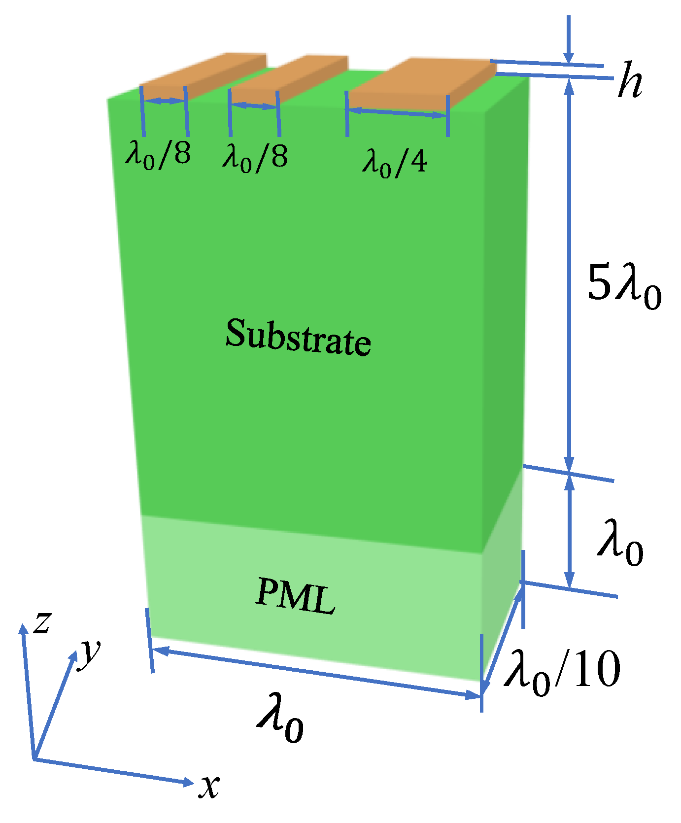
2.3. FEM Model Description and Simulation

The wave of the Rayleigh-type SAW propagates on the surface of the substrate with its amplitude exponentially decaying. This feature enables us to build a model with only a few wavelength depths of the substrate. The waves, excited by infinite numbers of the IDT fingers with the same grating shape on a piezoelectric substrate, are spatially periodic. Therefore, simulating a periodic structure of the device might suffice. With the use of periodic boundary conditions (PBC) in x- and y-directions, this model is reduced to one period λ0 in the x-direction and λ0/10 in the y-direction. Static analysis and eigenfrequency analysis are conducted in the FEM to extract the COM parameters. Here, we build the FEM model of a standard EWC SPUDT cell on a substrate to demonstrate the approach to extract the COM parameters.
As shown in Figure 2, a three-dimensional model with a period of λ0 = 50 μm, in which the IDT structure is a standard EWC SPUDT, is built. This standard EWC SPUDT has three fingers, with two λ0/8 narrow fingers and one λ0/4 wide finger, and the gaps between the fingers are λ0/8 and 3λ0/16. The first finger is active. In our model, we set the origin at the center of the period structure. A perfectly matched layer (PML) is applied to suppress the spurious resonances caused by the bottom reflection [30]. The thickness of electrodes is denoted by h and the thickness of the substrate and the PML are set as 5λ0 and λ0, respectively. Two electrodes on the right in the model are grounded, while the terminal one is 1V voltage or 0C charge, according to the request of the model analysis.
In Equation (3), the COM parameters can be interpreted as parameters for a unit length. Actually, the parameters for a unit period of length λ0 are more practical. Instead, it is convenient to define the normalized parameters listed in Table 1.
In static analysis, a voltage 1V is applied on the terminal electrode. After the model is solved, we can get the surface charge density σs(x1) and the tangential component of the electric field on the substrate surface E1(x1) and the surface potential Φ(x1), as shown in Figure 3.
The capacitance can be calculated by summing the electrostatic charges on the electrodes connected to the terminal of voltage.
The other COM parameters can be obtained from the results of the eigenfrequency analysis. In this analysis, the edge frequencies of the stopband fs+, fs−, fo+, fo− can be obtained. The two frequencies (fs+ and fs−) correspond to two eigenfrequencies (symmetric frequency and antisymmetric frequency) of the eigenfrequency analysis by setting the terminal voltage to 0V. Here, we also donate the lower of the two eigenfrequencies as fs− and the higher one as fs+, and they are 77.646 MHz and 78.079 MHz for 128° YX LiNbO3, respectively. The displacement distributions at the lower and upper stopband edges also can be obtained from the postprocessing of the eigenfrequency analysis in the FEM, and the normalized displacements are shown in Figure 4.
It can be seen that there is a π/2 phase difference between the two displacements distribution. One can get the phase φκ after finding the position of the displacement distribution at the lower edge frequency. Then, the COM parameters of ν, |κ| and φκ can be derived using Equations (8)–(12). Table 2 gives the calculated COM parameters for EWC SPUDT on 128°YX LiNbO3 with h = 0.
We have extracted the COM parameters [31] for EWC SPUDT on YZ-LiNbO3, bidirectional IDTs on 128°YX LiNbO3 and Y-Z LiNbO3. Moreover, these results are compared with those of well-known researchers in the field of surface acoustic waves (SAW), and that shows this approach is powerful to fully extract the COM parameters of the Rayleigh-type SAW for all kinds of IDT structures on arbitrary materials [20,32,33].
We modify the directivity D given in reference [18], which can be simplified to Equation (20):
D = | 1 + i exp ( i φ ) tanh ( N | κ p | 2 ) 1 + i exp ( i φ ) tanh ( N | κ p | 2 ) | ,
where φ = φκ − 2φα, we call it unidirectional angle, and N is the number of electrodes.
In Equation (20), the defined directivity is the ratio of the excitation efficiency of the IDT in positive x to the excitation efficiency in negative x. This means that the wave excitation in direction of positive x is favored over the negative x if D > 1, and the wave excitation in positive x is weaker than the negative x if D < 1, or else the period of an IDT cell on a given substrate is bidirectional. When fixed for the value N|κp|, one can find that the condition of the best right directivity is φ = −π/2. The sign of φ is important to decide the direction of the wave excited by the drive voltage is applied on IDTs. Definitely, one can get the sign of φ since all the COM parameters, including the phases of φκ and φα, can be calculated by our method.

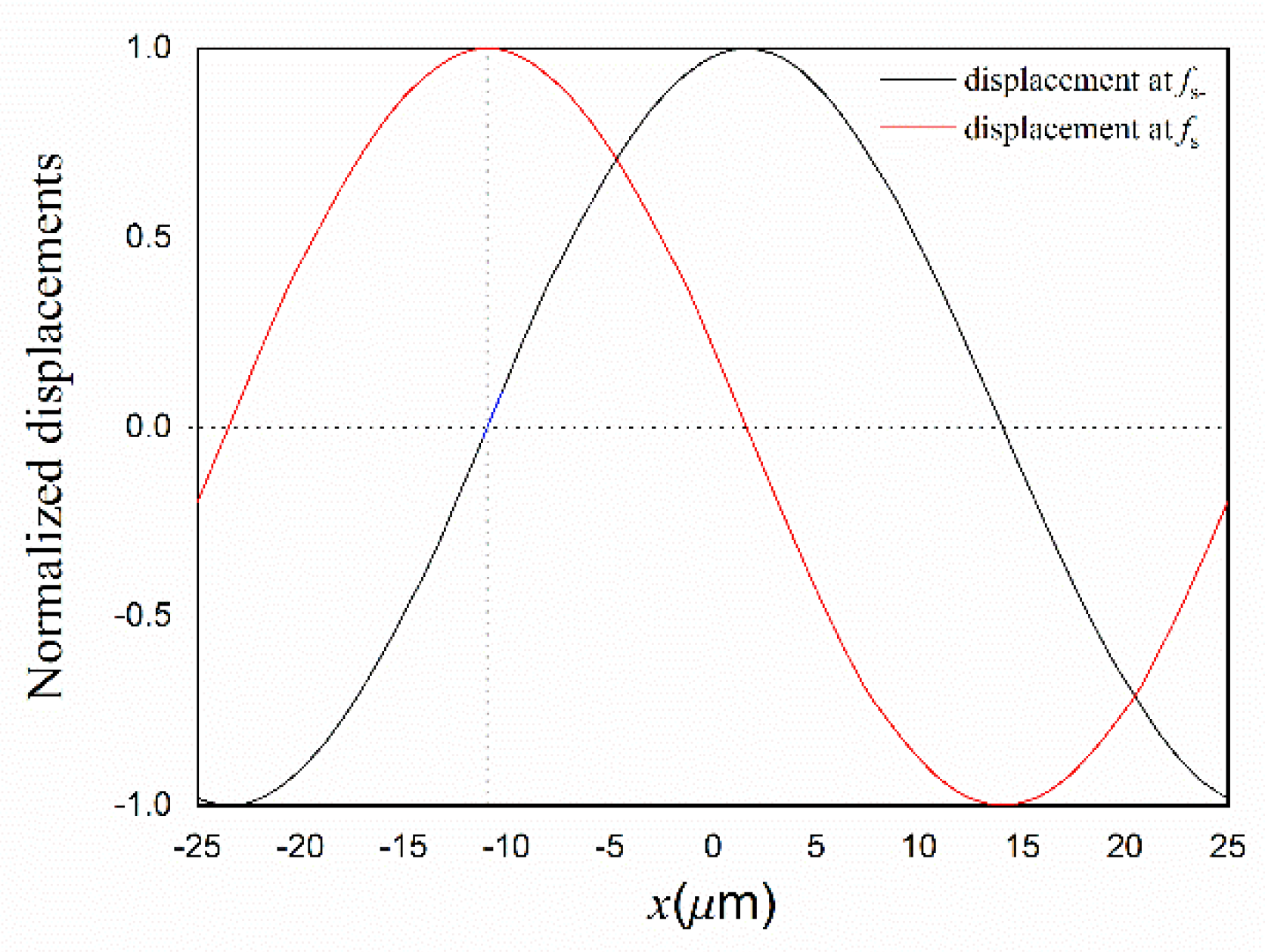
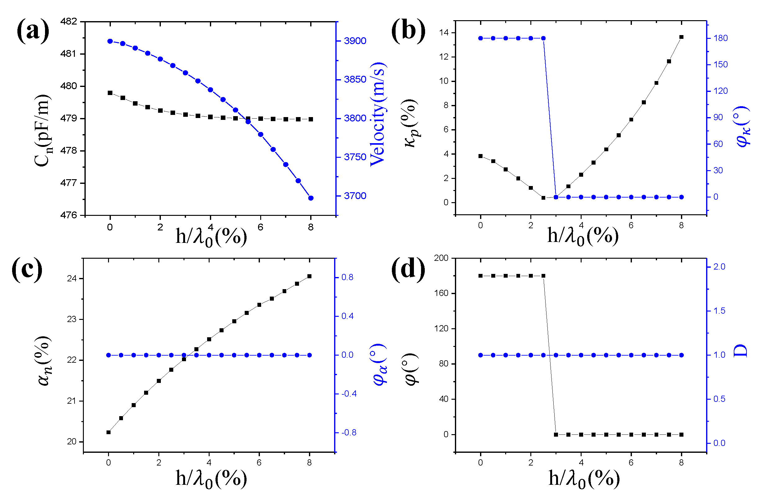
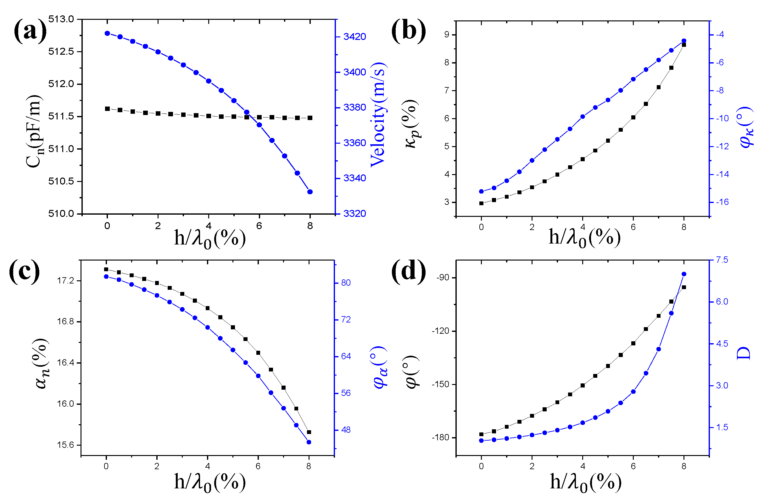
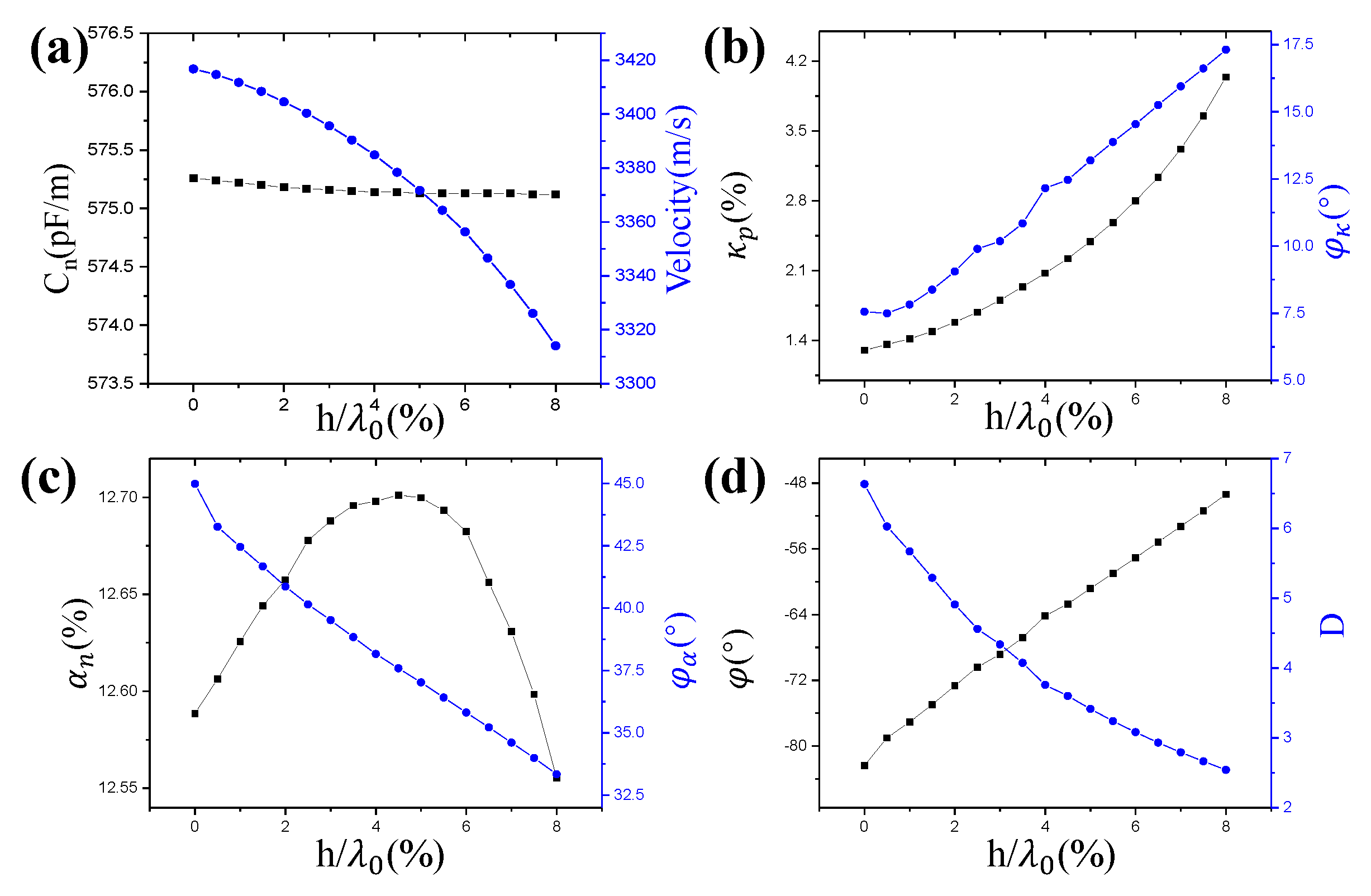
3. Results and Discussions

In this section, we compute the COM parameters versus the thickness of the electrode for the bidirectional IDT on the 128°YX LiNbO3, bidirectional IDT on Y-Z LiNbO3, EWC SPUDT on 128°YX LiNbO3 and EWC on Y-Z LiNbO3, respectively. The material constants of LiNbO3 are obtained from reference [34], and the metal electrodes are assigned with aluminum (Al) material with a Young’s modulus of 70 GPa, a Poisson’s ratio of 0.33 and a density of 2700 kg/m3.
Figure 5a–d illustrates the results of the COM parameters for the bidirectional IDT on the 128°YX LiNbO3. As shown in Figure 5a, with an increase of h0, the velocity ν decreases, while the capacitance C n has almost no change. Figure 5b shows the amplitude and the phase of κ. It is easy to see that |κ| decreases at first and then increases with the increase of h0, and it becomes zero at h0 ≈ 2.76%. This is due to the fact that the electrical reflection by the short-circuited grating has the opposite sign to the mechanical reflection [18]. The corresponding experiment results [35] verified its correctness. This phenomenon can be deduced from the phase φκ. When h0 is small, φκ = π, namely, κ < 0, and when h0 > 2.76%, φκ = 0, namely, κ > 0. This is to say that κ increases monotonically with an increase in h0. Figure 5c shows α n and the phase φα. We can see that the value of α n has a slowly increasing trend and that the phase remains the same at zero. The directivity and the unidirectional angle versus the thickness of the electrode are displayed in Figure 5d. It can be seen that the directivity has stayed at 1, indicating that the IDT is bidirectional and there is no natural unidirectionality in the material orientation. In Figure 5d, we can see the unidirectional angle is 0 or 180°. Substituting the unidirectional angle into Equation (20), the directivity of 1 also can be deduced.
Figure 6a–d illustrate the results of the COM parameters for the bidirectional IDT on the Y-Z LiNbO3. The COM parameters of C and ν have the same change trends compared with the bidirectional IDT on 128°YX-LiNbO3, while the value of α n has an opposite trend. From Figure 6b, the reflection coefficient increases without an inflection point and the phase φκ is offset by 0 slightly and increases slowly with h0. These features demonstrate that directivity is inherent in Y-Z LiNbO3 despite being very small. Additionally, the directivity can be adjusted slightly by changing the thickness of the electrode. It also can be seen from Figure 6d that the unidirectional angle is offset by 180° when h/λ0 increases, and the directivity increases as h0 increases.
Figure 7a–d and Figure 8a–d illustrate the results of the COM parameters for the EWC SPUDT on 128°YX LiNbO3 and Y-Z LiNbO3, respectively. These COM parameters of C, ν and α n have the same change trends in two cutting types of LiNbO3. The same is seen in the bidirectional IDT, where the |κp| has a zero [36] value in 128°YX-LiNbO3 when h0 is approximate to 2.47%, but such a zero value does not exist in YZ-LiNbO3. In relation to the |κp|, it is relatively small in the EWC SPUDT structure compared with the bidirectional IDT structure. From Figure 7d and Figure 8d, we can see that the unidirectional angles are close to −90° or 90°, but not −90° or 90° exactly. This means that the standard EWC SPUDT structure on 128°YX LiNbO3 and Y-Z LiNbO3 do not obtain the best directivity. From the directivity curve in Figure 7d, the wave excitation in the right direction is favored over the left wave when h0 is small, while when h0 is larger than 2.76%, this is reversed. This phenomenon has not appeared in previous research and is not found in YZ-LiNbO3.

4. Conclusions

A novel method is proposed to extract all the COM parameters, especially for the phases φκ and φα. This method fully utilizes the static and eigenfrequency characteristics computed by the FEM. The corresponding relationships between the characteristics obtained by the FEM and the characteristics in the COM theory are established. All the COM parameters for a bidirectional IDT cell on 128°YX LiNbO3, a bidirectional IDT cell on Y-Z LiNbO3, an EWC SPUDT cell on 128°YX LiNbO3 and an EWC SPUDT cell on Y-Z LiNbO3 are calculated, respectively. These examples show that this is an effective method to extract the COM parameters quickly, accurately, generally and fully.

Author Contributions

Conceptualization, X.S. (Xueping Sun), W.W. and W.L.; methodology, X.S. (Xueping Sun); software, X.S. (Xueping Sun) and R.M.; validation, X.S. (Xiuting Shao), W.W. and S.Z.; formal analysis, D.L.; investigation, X.S. (Xueping Sun); resources, W.W.; data curation, X.S. (Xueping Sun) and R.M.; writing—original draft preparation, X.S. (Xueping Sun); writing—review and editing, X.S. (Xueping Sun); visualization, X.S. (Xiuting Shao) and D.L.; supervision, W.W. and W.L.; project administration, W.L.; funding acquisition, J.C., X.S. (Xiuting Shao) and S.Z. All authors have read and agreed to the published version of the manuscript.

Funding

This research was funded by the Natural Science Basic Research Program of Shaanxi, grant number 2022JQ-676, and the Scientific Research Program of Shaanxi Provincial Education Department, grant number 21JY017, and the National Natural Science Foundation of China, grant number 11804201.

Institutional Review Board Statement

Not applicable.

Informed Consent Statement

Not applicable.

Data Availability Statement

Not applicable.

Conflicts of Interest

The authors declare no conflict of interest.

References

  1. Belyankova, T.; Vorovich, E.; Kalinchuk, V.; Tukodova, O. Specific features of SH-waves propagation in structures with prestressed inhomogeneous coating made of piezoceramics based on LiNbO 3. J. Adv. Dielectr. 2021, 11, 2160007. [Google Scholar] [CrossRef]
  2. Belyankova, T.; Vorovich, E.; Kalinchuk, V.; Tukodova, O. Peculiarities of surface acoustic waves, propagation in structures with functionally graded piezoelectric materials, coating from different ceramics on the basis of PZT. J. Adv. Dielectr. 2020, 10, 2060017. [Google Scholar] [CrossRef]
  3. Hofer, M.; Finger, N.; Kovacs, G.; Schoberl, J.; Zaglmayr, S.; Langer, U.; Lerch, R. Finite-element simulation of wave propagation in periodic piezoelectric SAW structures. IEEE Trans. Ultrason. Ferroelectr. Freq. Control 2006, 53, 1192–1201. [Google Scholar] [CrossRef] [PubMed]
  4. Koskela, J.; Plessky, V.; Willemsen, B.; Turner, P.; Hammond, B.; Fenzi, N. Hierarchical cascading algorithm for 2-D FEM simulation of finite SAW devices. IEEE Trans. Ultrason. Ferroelectr. Freq. Control 2018, 65, 1933–1942. [Google Scholar] [CrossRef] [PubMed]
  5. Willemsen, B.; Plesski, V.; Koskela, J. Fast, Highly Accurate, Full-Fem Surface Acoustic Wave Simulation. U.S. Patent 11,296,677, 5 April 2022. [Google Scholar]
  6. Li, X.; Bao, J.; Huang, Y.; Zhang, B.; Omori, T.; Hashimoto, K.-Y. Use of Hierarchical Cascading Technique for FEM Analysis of Transverse-Mode Behaviors in Surface Acoustic-Wave Devices. IEEE Trans. Ultrason. Ferroelectr. Freq. Control 2019, 66, 1920–1926. [Google Scholar] [CrossRef]
  7. Li, X.; Bao, J.; Qiu, L.; Matsuoka, N.; Omori, T.; Hashimoto, K.-Y. 3D FEM simulation of SAW resonators using hierarchical cascading technique and general purpose graphic processing unit. Jpn. J. Appl. Phys. 2019, 58, SGGC05. [Google Scholar] [CrossRef]
  8. Fernandez-Afonso, Y.; García-Zaldívar, O.; Calderón-Piñar, F. Equivalent circuit for the characterization of the resonance mode in piezoelectric systems. J. Adv. Dielectr. 2015, 5, 1550032. [Google Scholar] [CrossRef] [Green Version]
  9. Plessky, V.; Koskela, J. Coupling-of-modes analysis of SAW devices. Int. J. High Speed Electron. Syst. 2000, 10, 867–947. [Google Scholar] [CrossRef]
  10. Hartmann, C.; Abbott, B. Experimentally determining the transduction magnitude and phase and the reflection magnitude and phase of SAW SPUDT structures. In Proceedings of the IEEE Symposium on Ultrasonics, Honolulu, HI, USA, 4–7 December 1990; pp. 37–42. [Google Scholar]
  11. Kondratiev, S.; Thorvaldsson, T.; Sakharov, S.; Buzanov, O.; Medvedev, A. Extraction of COM parameters on langasite substrates and the application to design of a SAW filter. In Proceedings of the 2001 IEEE Ultrasonics Symposium. Proceedings. An International Symposium (Cat. No. 01CH37263), Atlanta, GA, USA, 7–10 October 2001; pp. 53–56. [Google Scholar]
  12. Ventura, P.; Hodé, J.; Solal, M.; Desbois, J.; Ribbe, J. Numerical methods for SAW propagation characterization. In Proceedings of the 1998 IEEE Ultrasonics Symposium. Proceedings (Cat. No. 98CH36102), Sendai, Japan, 5–8 October 1998; pp. 175–186. [Google Scholar]
  13. Dufilie, P.; Ventura, P.; Hecht, F. COM parameters for thick metal and partially buried electrodes extracted from a mixed FEM/BEM numerical model. In Proceedings of the 2012 IEEE International Ultrasonics Symposium, Dresden, Germany, 7–10 October 2012; pp. 807–810. [Google Scholar]
  14. Shaposhnikov, K.; Kaltenbacher, M.; Nicolay, P. Fast full-FEM computation of COM parameters. Application to multilayered SAW structures. In Proceedings of the 2014 IEEE International Ultrasonics Symposium, Chicago, IL, USA, 3–6 September 2014; pp. 1501–1504. [Google Scholar]
  15. Hashimoto, K.-Y.; Zheng, G.Q.; Yamaguchi, M. Fast analysis of SAW propagation under multi-electrode-type gratings with finite thickness. In Proceedings of the 1997 IEEE Ultrasonics Symposium Proceedings. An International Symposium (Cat. No. 97CH36118), Toronto, ON, Canada, 5–8 October 1997; pp. 279–284. [Google Scholar]
  16. Hashimoto, K.-Y.; Koskela, J.; Salomaa, M.M. Fast determination of coupling-of-modes parameters based on strip admittance approach. In Proceedings of the 1999 IEEE Ultrasonics Symposium. Proceedings. International Symposium (Cat. No. 99CH37027), Tahoe, NV, USA, 17–20 October 1999; pp. 93–96. [Google Scholar]
  17. Hartmann, C.; Wright, P.; Kansy, R.; Garber, E. An analysis of SAW interdigital transducers with internal reflections and the application to the design of single-phase unidirectional transducers. In Proceedings of the 1982 Ultrasonics Symposium, San Diego, CA, USA, 27–29 October 1982; pp. 40–45. [Google Scholar]
  18. Hashimoto, K.-y.; Hashimoto, K.-Y. Surface Acoustic Wave Devices in Telecommunications; Springer: Berlin/Heidelberg, Germany, 2000; Volume 116. [Google Scholar]
  19. Ruppel, C.C.; Fjeldly, T.A. Advances in Surface Acoustic Wave Technology, Systems and Applications; World Scientific: Singapore, 2001; Volume 20. [Google Scholar]
  20. Lin, J.; Wang, N.; Chen, H.; Shui, Y. Fast, precise, and full extraction of the COM parameters for multielectrode-type gratings by periodic Green’s function method. IEEE Trans. Ultrason. Ferroelectr. Freq. Control 2002, 49, 1735–1738. [Google Scholar]
  21. Chen, D.-P.; Haus, H.A. Analysis of metal-strip SAW gratings and transducers. IEEE Trans. Sonics Ultrason. 1985, 32, 395–408. [Google Scholar] [CrossRef]
  22. Hashimoto, K.-y.; Omori, T.; Ahn, C.-J. Extension of scalar potential formalism for transverse mode analysis of surface acoustic wave resonators. In Proceedings of the 2011 IEEE International Ultrasonics Symposium, Orlando, FL, USA, 18–21 October 2011; pp. 333–336. [Google Scholar]
  23. Huang, Y.; Bao, J.; Li, X.; Zhang, B.; Omori, T.; Hashimoto, K.-Y. Parameter extraction of coupling-of-modes equations including coupling between two surface acoustic waves on SiO2/Cu/LiNbO3 structures. Jpn. J. Appl. Phys. 2018, 57, 07LD13. [Google Scholar] [CrossRef]
  24. Abbott, B.P. A Coupling-of-Modes Model for SAW Transducers with Arbitrary Reflectivity Weighting; University of Central Florida: Orlando, FL, USA, 1989. [Google Scholar]
  25. Wu, T.-T.; Wang, S.-M.; Chen, Y.-Y.; Wu, T.-Y.; Chang, P.-Z.; Huang, L.-S.; Wang, C.-L.; Wu, C.-W.; Lee, C.-K. Inverse determination of coupling of modes parameters of surface acoustic wave resonators. Jpn. J. Appl. Phys. 2002, 41, 6610. [Google Scholar] [CrossRef]
  26. Chen, Y.-Y.; Wu, T.-T.; Chou, T.-T. Analysis of the frequency response of a dispersive IDT/ZnO/sapphire SAW filter using effective permittivity and the coupling of modes model. J. Phys. D Appl. Phys. 2003, 37, 120. [Google Scholar] [CrossRef]
  27. Alyakna, Y.Y.; Gulyaev, Y.V.; Kozlov, A.; PLESSKII, V. Infulence of modulation of the grrove depth of a Bragg reflective grating on the Rayleigh-wave reflection coefficient. Sov. Phys. Acoust.-USSR 1984, 30, 346–348. [Google Scholar]
  28. Sun, X.; Liu, W.; Ge, S.; Zhou, S.; Li, X.; Lin, D. Achieving both high electromechanical response and stable temperature behavior in Si/SiO2/Al/LiTaO3 sandwich structure. AIP Adv. 2019, 9, 035145. [Google Scholar] [CrossRef] [Green Version]
  29. Zhang, Y.-m.; Jin, J.; Li, H.-l.; Hu, H.-p. A novel method to extract COM parameters for SAW based on FEM. In Proceedings of the 2019 13th Symposium on Piezoelectrcity, Acoustic Waves and Device Applications (SPAWDA), Harbin, China, 11–14 January 2019; pp. 1–5. [Google Scholar]
  30. Dühring, M.B.; Laude, V.; Khelif, A. Energy storage and dispersion of surface acoustic waves trapped in a periodic array of mechanical resonators. J. Appl. Phys. 2009, 105, 093504. [Google Scholar] [CrossRef] [Green Version]
  31. Sun, X.; Zhou, S.; Cheng, J.; Lin, D.; Liu, W. Full extraction of the COM parameters for Rayleigh type surface acoustic wave. AIP Adv. 2022, 12, 025007. [Google Scholar] [CrossRef]
  32. Koskela, J.; Plessky, V.P.; Salomaa, M.M. SAW/LSAW COM parameter extraction from computer experiments with harmonic admittance of a periodic array of electrodes. IEEE Trans. Ultrason. Ferroelectr. Freq. Control 1999, 46, 806–816. [Google Scholar] [CrossRef]
  33. Lin, J.; Wu, H.; Wang, N.; Qiu, H.; Shui, Y.A. Precise and full extraction of the coupling-of-mode parameters with periodic Green’s function. Sci. China Ser. F Inf. Sci. 2003, 46, 298–308. [Google Scholar] [CrossRef]
  34. Kovacs, G.; Anhorn, M.; Engan, H.; Visintini, G.; Ruppel, C. Improved material constants for LiNbO/sub 3/and LiTaO/sub 3. In Proceedings of the IEEE symposium on ultrasonics, Honolulu, HI, USA, 4–7 December 1990; pp. 435–438. [Google Scholar]
  35. He, S.; Chen, D.; Wang, C. The Structures of SAW Single-electrode IDT without Internal Reflection and the Analysis on Their Properties. Piezoelectr. Acoustoopt. 1992, 14, 55–59. (In Chinese) [Google Scholar]
  36. Sun, X.; Liu, W.; Shao, X.; Zhou, S.; Wang, W.; Lin, D. Surface acoustic wave gyroscopic effect in an interdigital transducer. Sensors 2018, 19, 106. [Google Scholar] [CrossRef] [PubMed] [Green Version]
Figure 1. A SAW transducer.
Crystals 12 00706 g001
Figure 2. FEM model of a unit cell.
Crystals 12 00706 g002
Figure 3. Surface potential, surface charge density and tangential component of the electric field distribution under a periodic EWC SPUDT.
Crystals 12 00706 g003
Figure 4. Normalized displacement distributions at the lower and upper edge frequencies.
Crystals 12 00706 g004
Figure 5. COM parameters versus thickness of electrode for bidirectional IDT on 128°YX LiNbO3: (a) Normalized capacitance and velocity; (b) Reflection coefficient and its phase; (c) Normalized transduction coefficient and its phase; (d) The unidirectional angle and directivity.
Crystals 12 00706 g005
Figure 6. COM parameters versus thickness of electrode for bidirectional IDT on YZ-LiNbO3: (a) Normalized capacitance and velocity; (b) Reflection coefficient and its phase; (c) Normalized transduction coefficient and its phase; (d) The unidirectional angle and directivity.
Crystals 12 00706 g006
Figure 7. COM parameters versus thickness of electrode for EWC SPUDT on 128°YX-LiNbO3: (a) Normalized capacitance and velocity; (b) Reflection coefficient and its phase; (c) Normalized transduction coefficient and its phase; (d) The unidirectional angle and directivity.
Crystals 12 00706 g007
Figure 8. COM parameters versus thickness of electrode for EWC SPUDT on YZ-LiNbO3: (a) Normalized capacitance and velocity; (b) Reflection coefficient and its phase; (c) Normalized transduction coefficient and its phase; (d) The unidirectional angle and directivity.
Crystals 12 00706 g008
Table 1. Normalized COM parameters.
ParametersSymbolDimension (SI)
Velocity in short-circuited gratingνm/s
Reflection coefficientκp = κλ0%
Transduction coefficientαp = αλ0 Ω 1 2
Normalized transduction coefficient α n α p / ω C p %
CapacitanceCp = Cλ0F
Normalized capacitanceCn= Cp/WF/m
Table 2. COM parameters for EWC SPUDT on 128°YX LiNbO3 for h = 0.
ParametersValues
Normalized capacitance (pF/m)546.33
Velocity in short-circuited grating (m/s)3892.7
Reflection coefficient |κp| (%)1.73
Phase of reflection coefficient−157.56°
Normalized transduction coefficient α n (%)14.68
Phase of transduction coefficient−37.84°
Publisher’s Note: MDPI stays neutral with regard to jurisdictional claims in published maps and institutional affiliations.

