Morphology Investigation on Cyclopentane Hydrate Formation/Dissociation in a Sub-Millimeter-Sized Capillary

1
State Key Laboratory of Heavy Oil Processing, China University of Petroleum-Beijing, Beijing 102249, China
2
Department of Engineering, China University of Petroleum-Beijing at Karamay, Sinkang 834000, China
*
Author to whom correspondence should be addressed.
Crystals 2019, 9(6), 307; https://0-doi-org.brum.beds.ac.uk/10.3390/cryst9060307
Submission received: 24 April 2019
/
Revised: 4 June 2019
/
Accepted: 6 June 2019
/
Published: 14 June 2019
Abstract
:The formation, dissociation, and reformation of cyclopentane (CP) hydrate in a sub-millimeter-sized capillary were conducted in this work, and the morphology of CP hydrate was obtained during above processes, respectively. The influences of the supercooling degree, i.e., the hydrate formation driving force, on CP hydrate crystals’ aspect and growth rate were also investigated. The results demonstrate that CP forms hydrate with the water melting from ice at the interface between the CP and melting water at a temperature slightly above 273.15 K. With the action of hydrate memory effect, the CP hydrate in the capillary starts forming at the CP-water interface or CP–water–capillary three-phase junction and grows around the CP–water interface. The appearance and growth rate of CP hydrate are greatly influenced by the supercooling degree. It indicates that CP hydrate has a high aggregation degree and good regularity at a high supercooling degree (or a low formation temperature). The growth rate of CP hydrate crystals greatly increases with the supercooling degree. Consequently, the temperature has a significant influence on the formation of CP hydrate in the capillary. That means the features of CP hydrate crystals in a quiescent system could be determined and controlled by the temperature setting.
1. Introduction
Hydrates are a kind of crystalline compound, which is usually formed by water and gas molecules at the proper temperature (T) and pressure (P) [1,2]. Most common gases, such as CH4, CO2, N2, O2, tetrahydrofuran (THF), and cyclopentane (CP), are able to form hydrates at different T-P conditions [3,4]. In hydrates, water molecules (host molecules) build cavities with a specific shape and size through a hydrogen-bond interaction, and gas molecules (guest molecules) are encaged in the cavities and stabilize the cavity structure [5,6]. The interaction between host and guest molecules is Van der Waals force [7]. The molecular size of the gas should be suitable for the size of the cavity in order to form stable hydrates. Consequently, different guest molecules should form hydrates with different structures, i.e., structure I, II, and H [8,9].
Since Hammerschmidt found natural gas pipeline blocking caused by hydrate formation in 1934 [10], gas hydrates have attracted extensive attention in industrial circles. So far, hydrates could potentially be applied to natural gas storage and transportation [11,12,13], gas mixture separation [14,15], CO2 capture and sequestration [16,17], sea water desalination [18,19], and so on. The study of hydrate-based technologies has obtained considerable development and great progress in the past decades. It is believed that the study of CP hydrate formation and dissociation has great significance for the flow assurance of oil/gas [20]. Just like most gaseous guest molecules of hydrates, CP is difficult to dissolve in water. In addition, CP forms hydrates at relatively mild conditions. Therefore, CP is frequently used as a hydrate-former (guest molecule) for hydrate formation and dissociation research [4,19,20,21].
At the same time, the size of the reactor for hydrate formation also has great influence on the thermodynamics or kinetics of hydrates. For example, the porous media with strong interfacial effect influences the formation/dissociation kinetics of hydrates [22]. Thereby, the study of gas hydrates in porous media has great significance to both the upstream and the downstream of the oil and gas industry. So far, the study of hydrates in porous media is generally carried out in a macroscopic hydrate reactor loaded with porous material [23,24]. The knowledge of small-scale features of hydrates in porous media is relatively limited. In fact, the microscopic observation and study of hydrates enables researchers to study and understand the behavior, characteristics, and rules of hydrate formation/dissociation [25,26,27,28]. Consequently, we conducted the formation and dissociation of CP hydrate in a special porous medium, i.e., a transparent sub-millimeter-sized capillary, in this work and investigated the features of CP hydrate in a capillary accordingly.
2. Experimental Section
2.1. Materials
The specifications and suppliers of experimental materials are presented in Table 1. A cuboid-shaped capillary with a side length of 500 μm and a length of 10 cm was manufactured using a micromachining method.
2.2. Apparatus
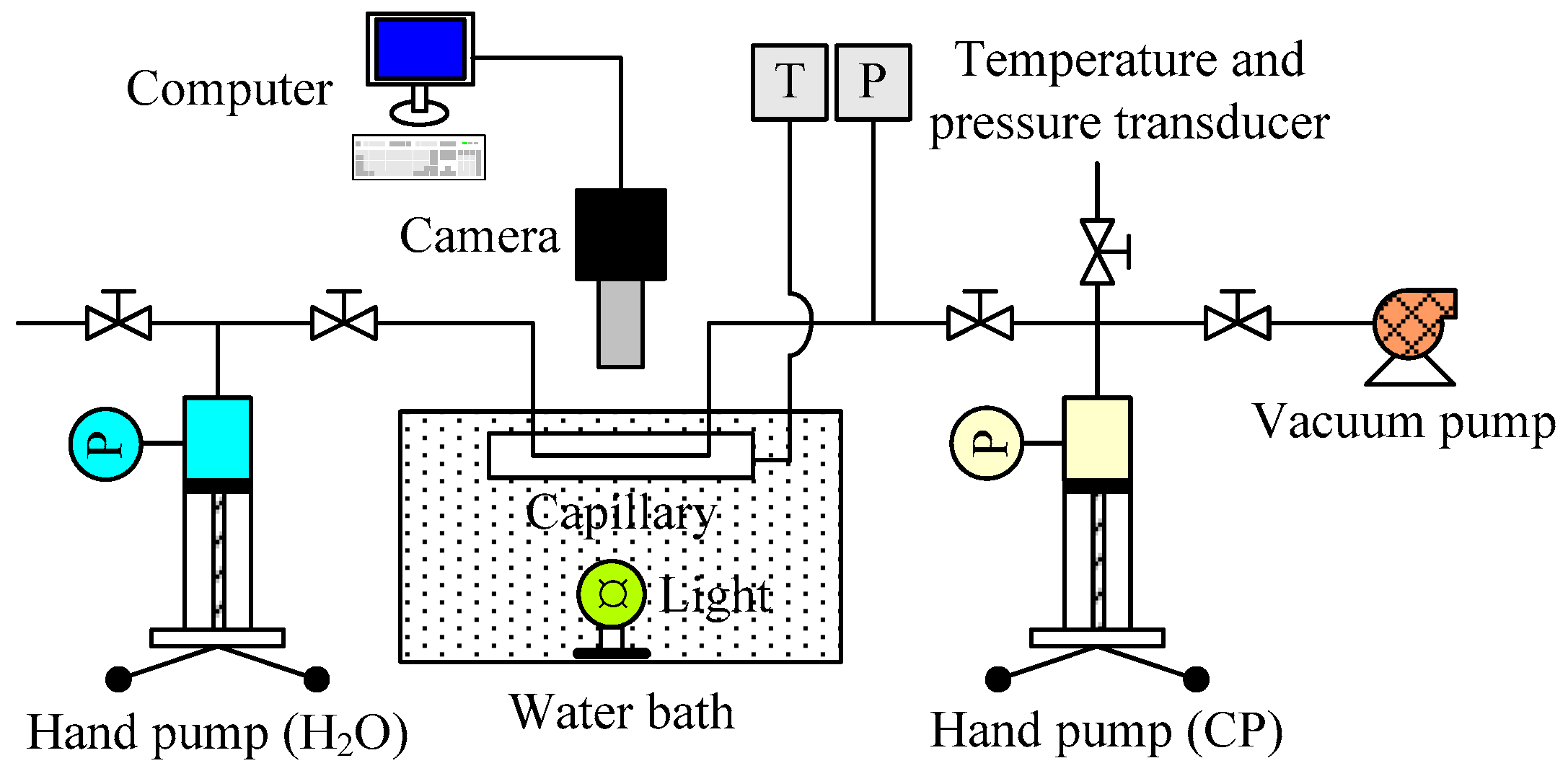
The schematic diagram of the experimental apparatus is shown in Figure 1. It mainly consists of a vacuum pump, two hand pumps, a water bath with a light source, a capillary, a high-resolution camera, and temperature and pressure transducers. The vacuum pump is used to eliminate gaseous impurities in the apparatus. The two hand pumps are used to maintain the desired pressure and CP–water interface position in the capillary. The water bath provides the reaction system with the desired experimental temperature. The capillary is made of acrylic sheets and completely immersed in the water bath. The temperature and pressure of the reaction system are measured by two transducers with an accuracy of 0.1 K and 0.01 MPa, respectively. The formation and dissociation phenomena of CP hydrate crystals in the capillary are displayed by the camera and recorded by a computer.
2.3. Procedure
Due to the quiescent contact and poor mass transfer effect between CP and water in the capillary, it takes a long time for CP to form hydrate crystals, even under a high supercooling degree [28]. However, the presence of hydrate seed or water from ice melting could significantly shorten the induction time for hydrate reformation [29]. This could be attributed to the memory effect of hydrate [30]. Consequently, the capillary loaded with CP and water was first dipped into liquid nitrogen (where ice generated), and then put into a water bath with an initial temperature of 270.15 K. With the increase in temperature, CP hydrate formed first at the CP–ice interface at a temperature of slightly above 273.15 K [31,32]. As the temperature increased to a value (Tdis) slightly higher than the phase equilibrium temperature (Teq ≈ 280.15 K), CP hydrate completely dissociated. The above period for the temperature rise is defined as dissociation time (tdis) in this work. After that, the temperature of the water bath was set to a lower value (supercooled temperature, Tsup) to make CP reform hydrate with the action of a memory effect (water from hydrate immediate dissociation). The driving force (supercooling degree) of CP hydrate reformation in a capillary is the temperature difference (ΔT) between Teq and Tsup. The temperature profile of the reaction system during the above process is shown in Figure 2. The phenomena of CP hydrate crystal formation and dissociation in a capillary were observed and recorded over time. Each process (generation of ice, first formation, dissociation, and reformation of CP hydrate) was repeated two to three times to reduce the experimental error.
3. Experimental Results and Discussion
3.1. First Formation of CP Hydrate Crystals in Capillary
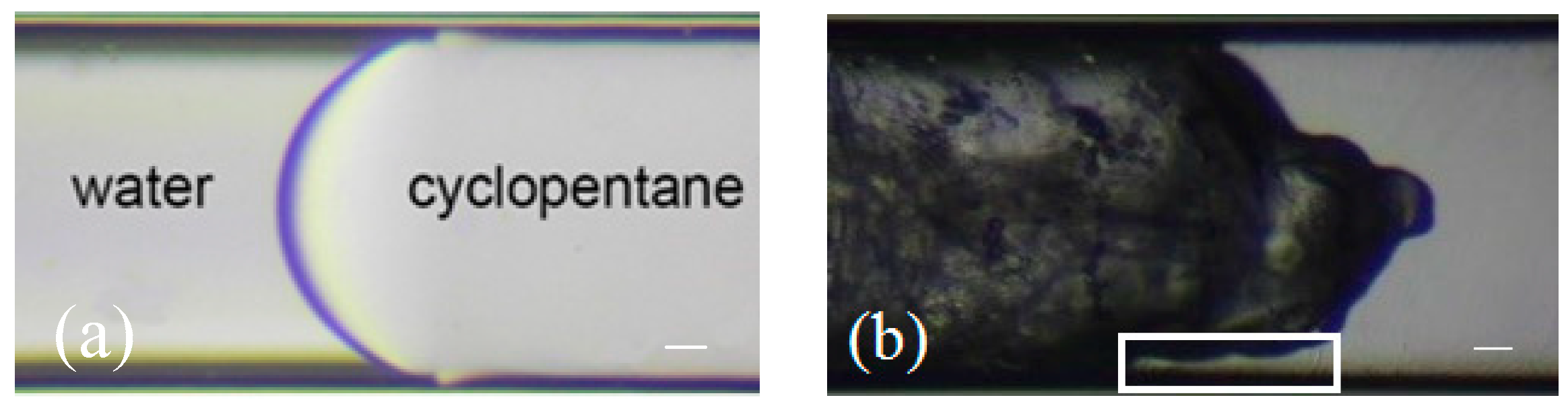
CP and water were first introduced into the water-wet capillary at atmospheric pressure and room temperature. An interface appeared between CP and water, as shown in Figure 3a. The interface looked shiny because of the different refractive index of light between CP and water. After the capillary was contacted with liquid nitrogen, liquid water changed to solid ice, as shown in Figure 3b. The calorimetric study results show that CP hydrate could not form readily at the current low T [33]. This could also be reflected by the gap between the solid edge and capillary inner wall (box in Figure 3b). It indicates that ice and CP coexisted steadily in a quiescent system at a temperature of 240.15 K. CP could not form hydrate with ice at the current condition. On the contrary, CP formed hydrate with the water from ice melting at their interface at a temperature slightly above 273.15 K (shown in Figure 4c). Meanwhile, the meniscus direction of the interface between CP and ice in Figure 3b was opposite that of CP and water in Figure 3a, which resulted from icing and the related volume expansion. Consequently, the solid mixture was dominated by ice at this moment.
3.2. Melting of Ice, First Formation, and Dissociation of CP Hydrate in the Capillary
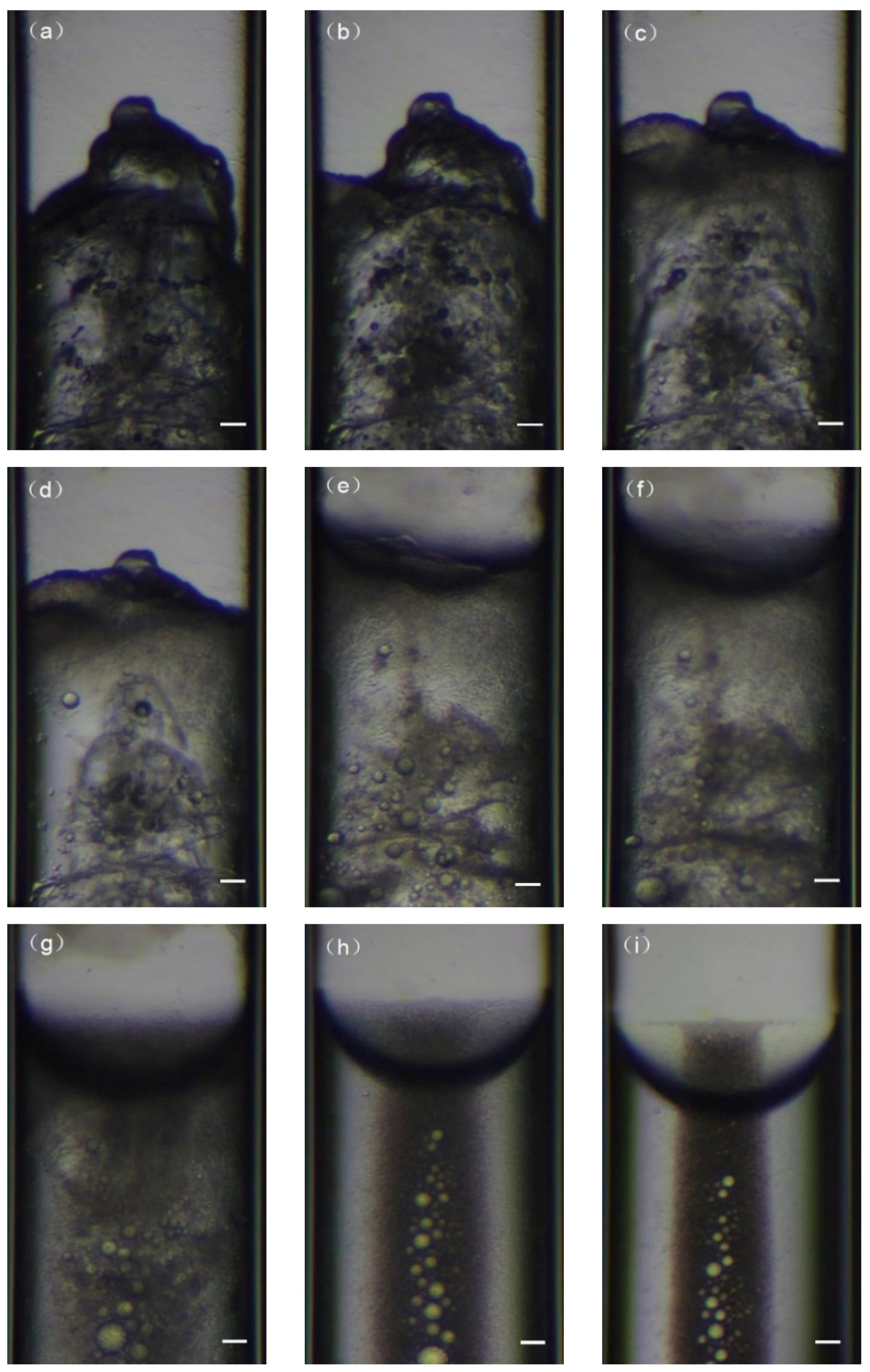
Figure 4 illustrates the melting of ice, first formation, and dissociation of CP hydrate in the capillary at atmosphere pressure. CP and ice were first put into a water bath with a temperature of 270.15 K, as shown in Figure 4a and then passed through a temperature-rise period. The state of the reactants in the capillary hardly changed until the temperature reached 273.65 K, when the shape of CP–solid interface distorted obviously, as shown in Figure 4b. It indicates that CP began to form hydrate with the water from the melting ice. When the temperature rose to 274.15 K, the protuberance shape of the CP–solid interface almost flattened, as shown in Figure 4c. The gaps between solid edge and capillary walls disappeared and filled with new solids, which was believed to be CP hydrate. This could be inferred from the appearance difference between the newly formed solids and the pre-existing ones on the central axis of capillary. The new solids, i.e., CP hydrate, looks homogenous with a fine texture. By contrast, the pre-existing solid, composed of ice, appeared irregularly with uneven grains. The solid body extended toward the CP phase, which also demonstrates that CP was consuming, and CP hydrate crystals were generating. At the same time, the outline of the ice phase bulk around the central axis in the capillary shrunk gradually. However, when the temperature reached above 275.15 K, the CP hydrate–ice phase looked transparent, and colloidal substance appeared in the phase, as shown in Figure 4d–f. The pre-existing protuberance of the CP–solid interface disappeared and trended to become a meniscus, and some dark small particles existed in the hydrate–ice phase. The existence of colloidal substance and the dark unordered particles demonstrates that CP hydrate was dissociating. This occurred because the current temperature was too high for CP to form hydrate with the melting water [32]. When the temperature rose to a higher value (Tdis), the quantity of colloidal substance decreased distinctly, as shown in Figure 4g. After a period at constant Tdis, the colloidal form looked transparent. The interface between CP and water arose more clearly, and bright and well-ordered CP droplets appeared in the water bulk phase, as shown in Figure 4h. Finally, CP droplets became smaller and fewer, and the color halo of the CP–water interface emerged again, as shown in Figure 4i. It indicates that the CP hydrate crystals dissociated completely.
3.3. Reformation Process and Appearance of CP Hydrate Crystals in Capillary
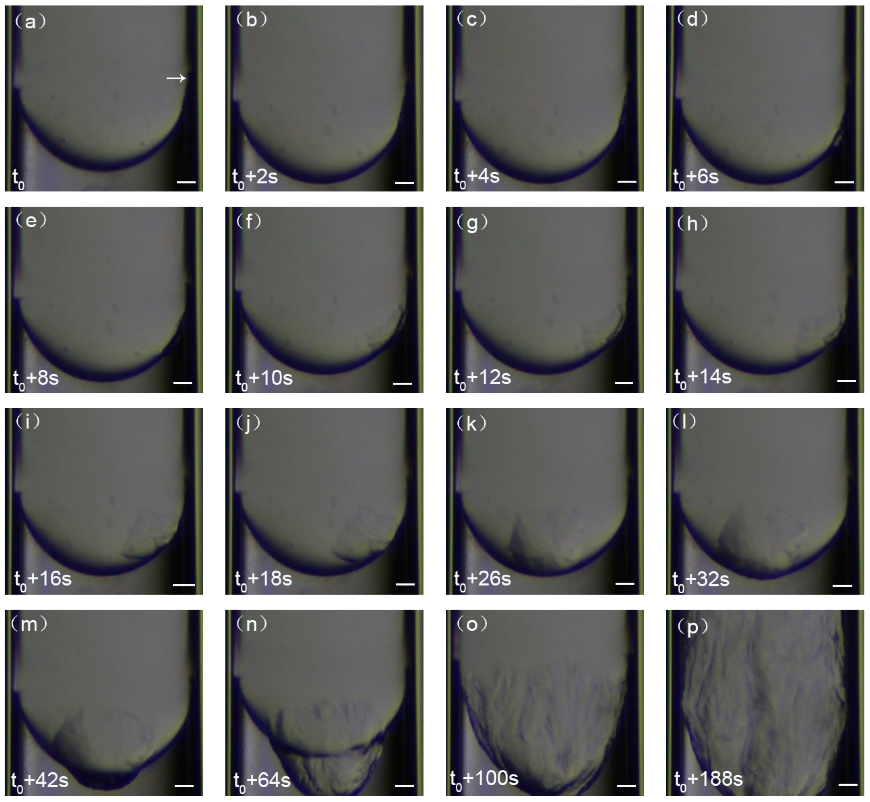
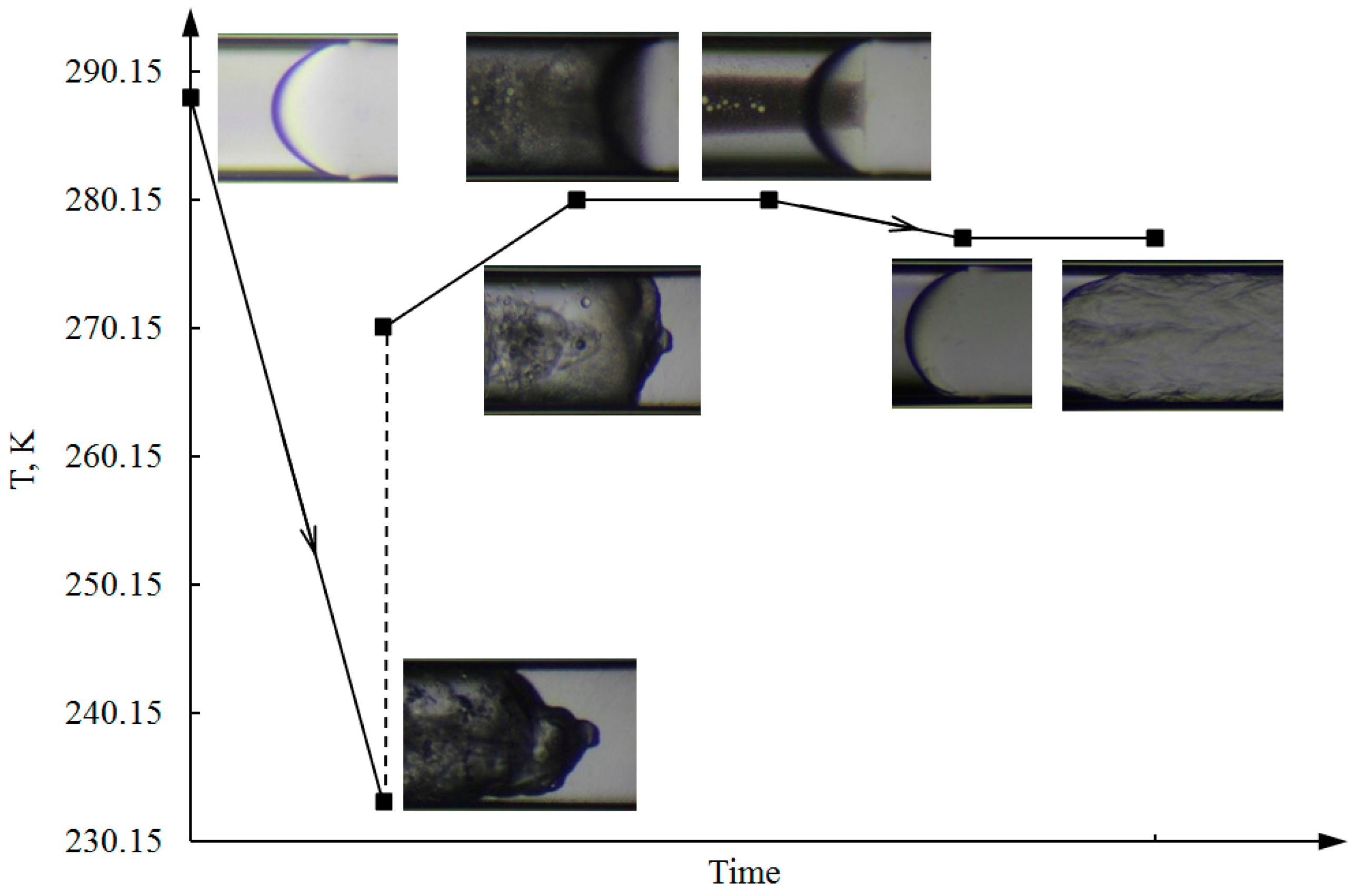
After CP hydrate dissociated in a time of tdis (20 minutes) at a temperature of Tdis (282.15 K), the temperature of reactants in the capillary was cooled to 277.15 K (Tsup) to make CP reform hydrate with the action of a hydrate memory effect, as shown in Figure 5. The reformation of CP hydrate started from the joint of the CP–water–capillary wall, where a tiny crystal particle appeared, as indicated by the white arrow in Figure 5a. This occurred because the temperature there was lowest in the capillary, which is the closest to that of the outside surroundings (Tsup). It indicates that CP hydrate generally starts forming very near or at the water–CP interface, although hydrate nucleation is a stochastic process. The hydrate particle grew afterwards in the CP phase and slid along the CP–water interface to the central apex, as shown in Figure 5b–k. During this period, the shape of the CP–water meniscus hardly changed. After reaching the apex of CP–water interface, CP hydrate crystals began to grow towards the water phase and the CP phase simultaneously, as shown in Figure 5l,m. The CP–water interface was covered with a polycrystalline crust, resulting in the deformation of CP–water meniscus, as shown in Figure 5n. The CP–water meniscus at the apex gradually faded away, and a new CP hydrate–water interface emerged. In addition, the appearance of the CP hydrate crystals at this moment was not flat but bumpy. It indicates that the aggregation extent of the CP hydrate was increasing. Afterwards, the polycrystalline crust kept growing over the capillary wall, which has been referred to as a “halo” [25,34,35], as shown in Figure 5o,p. The degree of unevenness of CP hydrate looked more intensive. The morphology of CP hydrate with the temperature profile at different times is shown in Figure 6.
3.4. Influence of Supercooling Degree on CP Hydrate Crystals Reformation
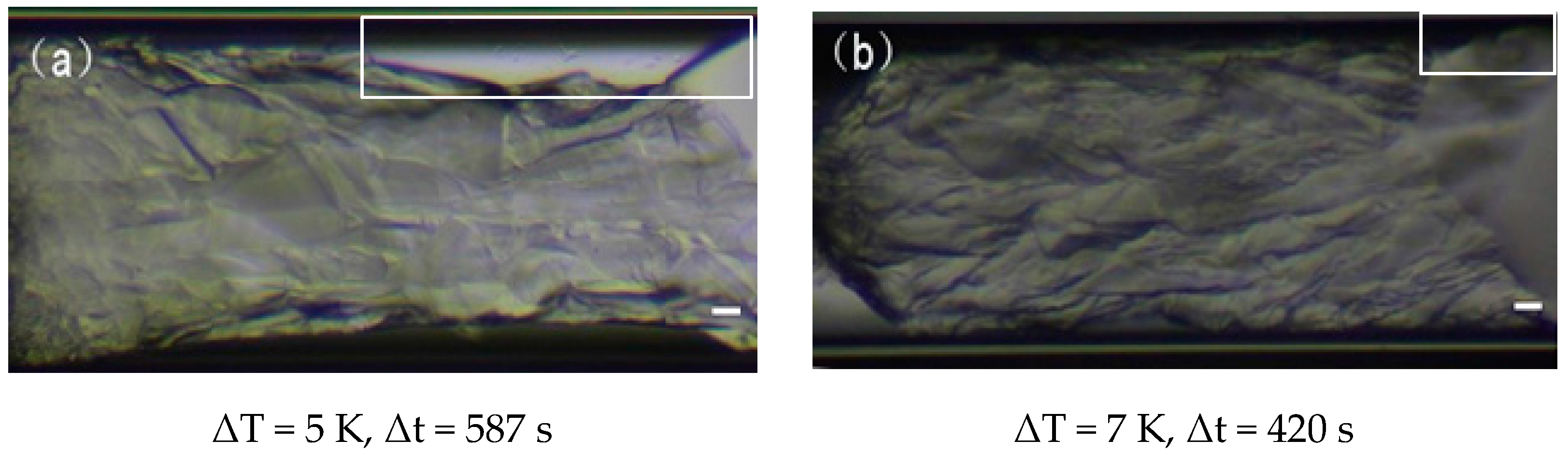
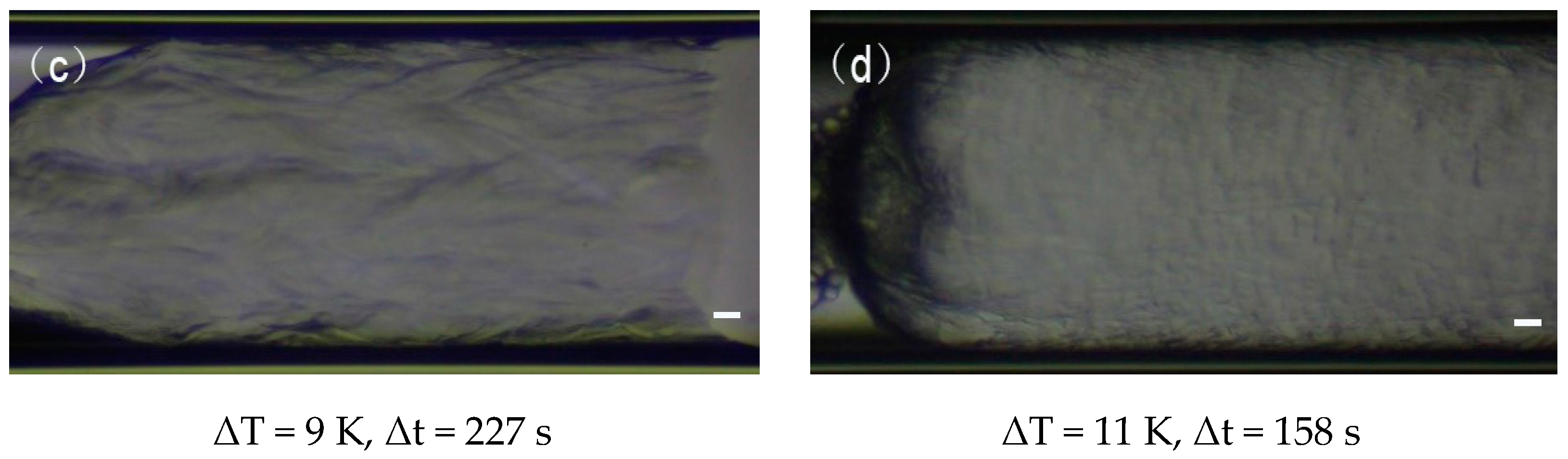
After CP hydrate dissociated completely at Tdis in capillary, it is definite that the temperature (Tsup) for CP hydrate reformation influenced the aspect and growth rate of the hydrate halo, i.e., the supercooling degree (△T) influenced the morphology and formation kinetics of the CP hydrate. Figure 7 displays the snapshots and time (△t) of CP hydrate halos grown from the CP–water interface to the same distance (≈ 985 μm) in the CP phase at different △T.
At a low supercooling degree (△T = 5 K in Figure 7a), CP hydrate crystals appeared obviously layered and sheet-like. A long gap appeared and existed between CP hydrate and capillary inner wall along with the CP hydrate formation, as shown in the box of Figure 7a. The substance in the gap was considered to be water, which could be inferred by the incomplete shining CP–water interface, similar to Figure 3a. It indicates CP hydrate formed deficiently at a supercooling degree, and it seems thin and crispy. As supercooling degree increased (△T = 7 K in Figure 7b), the water gap between CP hydrate and the capillary wall could hardly be observed. However, there was a clear wetting angle between the CP bulk phase and the capillary wall, as shown in the box of Figure 7b. CP hydrate crystals also looked layered and flaky but more compact than at △T = 5 K. As Tsup decreased further (△T = 9 K in Figure 7c), the wetting angle between the CP phase and the capillary almost disappeared, and CP hydrate crystals looked like slender strips. When the supercooling degree reached 11 K, shown in Figure 7d, CP hydrate appeared more uniform and denser than at △T = 9 K. It seems that the surface of the CP hydrate crystals hardly had lacuna. In conclusion, CP hydrate had a high aggregation degree and a good regularity at a high supercooling degree. It looked solid, dense, and compact. In other words, the morphology and property of the CP hydrate could be controlled by the supercooling degree.
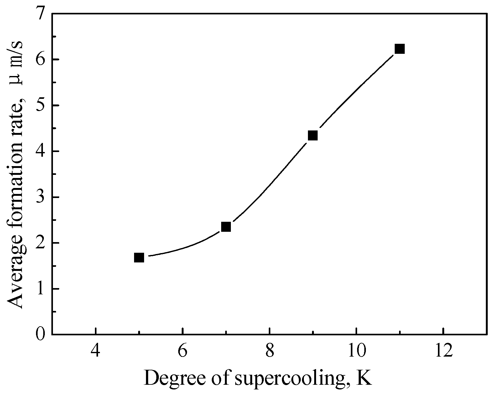
In addition, the supercooling degree also influenced the growth rate of CP hydrate crystals. It took less time for CP hydrate to grow to the same length at a higher supercooling degree, which means the growth rate of CP hydrate markedly increased with the supercooling degree, as shown in Figure 8.
4. Conclusions
We focused on CP hydrate crystal formation, dissociation, and reformation in a sub-millimeter-sized capillary in this work. The morphology of CP hydrate was obtained respectively, and the influence of the supercooling degree on CP hydrate reformation was investigated. The results demonstrate that CP formed hydrate with the water melting from ice at the CP–water interface at a temperature slightly above 273.15 K. Consequently, the temperature significantly influenced the transformation of CP–water–ice–CP hydrate. CP hydrate started to form at the CP–water–capillary three-phase junction and grew on the CP–water meniscus. The supercooling degree influenced both the aspect and growth rate of CP hydrate. CP hydrate has a high aggregation degree and a good regularity at a high supercooling degree. The growth rate of CP hydrate crystals strongly increased with the supercooling degree. It indicates that the formation of CP hydrate and the corresponding features are determined by the supercooling degree.
Author Contributions
Experimental operation—M.D.; Supervision and writing—Q.S.; Design—X.L. and X.G.; Instrumental analysis—L.Y.
Funding
This work was supported by Science Foundation of China University of Petroleum, Beijing (2462017BJB05, 2462016YJRC005, and 2462018BJC004), National Natural Science Foundation of China (21306226, 21808238), Science Foundation of CUPBK (RCYJ2017A-02-001, RCYJ2017A-03-001), which are greatly acknowledged.
Conflicts of Interest
The authors declare that they have no conflict of interest.
References
- Sloan, E.D.; Koh, C.A. Clathrate Hydrates of Natural Gases, 3rd ed.; CRC Press: Boca Raton, FL, USA, 2008. [Google Scholar]
- Englezos, P. Clathrate hydrates. Ind. Eng. Chem. Res. 1997, 32, 1251–1274. [Google Scholar] [CrossRef]
- Khurana, M.; Veluswamy, H.P.; Daraboina, N.; Linga, P. Thermodynamic and kinetic modelling of mixed CH4-THF hydrate for methane storage application. Chem. Eng. J. 2019, 370, 760–771. [Google Scholar] [CrossRef]
- Delroisse, H.; Torré, J.P.; Dicharry, C. Effect of a hydrophilic cationic surfactant on cyclopentane hydrate crystal growth at the water/cyclopentane interface. Cryst. Growth Des. 2017, 17, 5098–5107. [Google Scholar] [CrossRef]
- Aman, Z.M.; Koh, C.A. Interfacial phenomena in gas hydrate systems. Chem. Soc. Rev. 2016, 45, 1678–1690. [Google Scholar] [CrossRef] [PubMed]
- Sloan, E.D. Natural gas hydrates. J. Pet. Technol. 1991, 43, 1414–1417. [Google Scholar] [CrossRef]
- Van der Waals, J.A.; Platteeuw, J.C. Clathrate solutions. Adv. Chem. Phys. 1959, 2, 1–57. [Google Scholar]
- Tse, J.S.; McKinnon, W.R.; Marchi, M. Thermal expansion of structure I ethylene oxide hydrate. J. Phys. Chem. 1987, 91, 4188–4193. [Google Scholar] [CrossRef]
- Ripmeester, J.A.; Ratcliffe, C.I. Xenon-129 NMR studies of clathrate hydrates: New guests for structure II and structure H. J. Phys. Chem. 1990, 94, 876–877. [Google Scholar] [CrossRef]
- Hammerschmidt, E.G. Formation of gas hydrates in natural gas transmission lines. Ind. Eng. Chem. 1934, 26, 851–855. [Google Scholar] [CrossRef]
- Ruffine, L.; Broseta, D.; Desmedt, A. Gas Hydrates 2: Geoscience Issues and Potential Industrial Applications, 1st ed.; ISTE Ltd.: London, UK; John Wiley & Sons, Inc.: Hoboken, NJ, USA, 2018. [Google Scholar]
- Taheri, Z.; Shabani, M.R.; Nazari, K.; Mehdizaheh, A. Natural gas transportation and storage by hydrate technology: Iran case study. J. Nat. Gas Sci. Eng. 2014, 21, 846–849. [Google Scholar] [CrossRef]
- Skovborg, P.; Rasmussen, P. A mass transport limited model for the growth of methane and ethane gas hydrates. Chem. Eng. Sci. 1994, 49, 1131–1143. [Google Scholar] [CrossRef]
- Naeiji, P.; Mottahedin, M.; Varaminian, F. Separation of methane–ethane gas mixtures via gas hydrate formation. Sep. Purif. Technol. 2014, 123, 139–144. [Google Scholar] [CrossRef]
- Sun, Q.; Liu, J.; Liu, A.; Guo, X.; Yang, L.; Zhang, J. Experiment on the separation of tail gases of ammonia plant via continuous hydrates formation with TBAB. Int. J. Hydrogen Energy 2015, 40, 6358–6364. [Google Scholar] [CrossRef]
- Badu, P.; Linga, P.; Kumar, R.; Englezos, P. A review of the hydrate based gas separation (HBGS) process for carbon dioxide pre-combustion capture. Energy 2015, 85, 261–279. [Google Scholar]
- Tohidi, B.; Yang, J.; Salehabadi, M.; Anderson, R.; Chapoy, A. CO2 Hydrates could provide secondary safety factor in subsurface sequestration of CO2. Environ. Sci. Technol. 2010, 44, 1509–1514. [Google Scholar] [CrossRef] [PubMed]
- Han, S.; Rhee, Y.; Kang, S. Investigation of salt removal using cyclopentane hydrate formation and washing treatment for seawater desalination. Desalination 2017, 404, 132–137. [Google Scholar] [CrossRef]
- Lv, Q.; Li, X.; Li, G. Seawater desalination by hydrate formation and pellet production process. Energy Procedia 2019, 158, 5144–5148. [Google Scholar] [CrossRef]
- Adamova, T.P.; Stoporev, A.S.; Manakov, A.Y. Visual studies of methane hydrate formation on the water−oil boundaries. Cryst. Growth Des. 2018, 18, 6713–6722. [Google Scholar] [CrossRef]
- Baek, S.; Ahn, Y.H.; Zhang, J.; Min, J.; Lee, H.; Lee, J.W. Enhanced methane hydrate formation with cyclopentane hydrate seeds. Appl. Energy 2017, 202, 32–41. [Google Scholar] [CrossRef]
- Chen, X.; Espinoza, D.N. Surface area controls gas hydrate dissociation kinetics in porous media. Fuel 2018, 234, 358–363. [Google Scholar] [CrossRef]
- Zhang, B.; Zheng, J.; Yin, Z.; Liu, C.; Wu, Q.; Wu, Q.; Liu, C.; Gao, X.; Zhang, Q. Methane hydrate formation in mixed-size porous media with gas circulation: Effects of sediment properties on gas consumption, hydrate saturation and rate constant. Fuel 2018, 233, 94–102. [Google Scholar] [CrossRef]
- Wang, P.; Yang, M.; Chen, B.; Zhao, Y.; Zhao, J.; Song, Y. Methane hydrate reformation in porous media with methane migration. Chem. Eng. Sci. 2017, 168, 344–351. [Google Scholar] [CrossRef]
- Beltrán, J.G.; Servio, P. Morphological investigations of methane-hydrate films formed on a glass surface. Cryst. Growth Des. 2010, 10, 4339–4347. [Google Scholar] [CrossRef]
- Aifaa, M.; Kodama, T.; Ohmura, R. Crystal growth of clathrate hydrate in a flowing liquid water system with methane gas. Cryst. Growth Des. 2015, 15, 559–563. [Google Scholar] [CrossRef]
- Touil, A.; Broseta, D.; Hobeika, N.; Brown, R. Roles of wettability and supercooling in the spreading of cyclopentane hydrate over a substrate. Langmuir 2017, 33, 10965–10977. [Google Scholar] [CrossRef]
- Martinez de Baňos, M.L.; Carrier, O.; Bouriat, P.; Broseta, D. Droplet-based millifluidics as a new tool to investigate hydrate crystallization: Insights into the memory effect. Chem. Eng. Sci. 2015, 123, 564–572. [Google Scholar] [CrossRef]
- Sefidroodi, H.; Abrahamsen, E.; Kelland, M.A. Investigation into the strength and source of the memory effect for cyclopentane hydrate. Chem. Eng. Sci. 2013, 87, 133–140. [Google Scholar] [CrossRef]
- Zhao, J.; Wang, C.; Yang, M.; Liu, W.; Xu, K.; Liu, Y.; Song, Y. Existence of a memory effect between hydrates with different structures (I, II, and H). J. Nat. Gas Sci. Eng. 2015, 26, 330–335. [Google Scholar] [CrossRef]
- Takeya, S.; Hori, A.; Hondoh, T.; Uchida, T. Freezing-memory effect of water on nucleation of CO2 hydrate crystals. J. Phys. Chem. 2000, 104, 4164–4168. [Google Scholar] [CrossRef]
- Zylyftari, G.; Ahuja, A.; Morris, J.F. Nucleation of cyclopentane hydrate by ice studied by morphology and rheology. Chem. Eng. Sci. 2014, 116, 497–507. [Google Scholar] [CrossRef]
- Karanjkar, P.U.; Lee, J.W.; Morris, J.F. Calorimetric investigation of cyclopentane hydrate formation in an emulsion. Chem. Eng. Sci. 2012, 68, 481–491. [Google Scholar] [CrossRef]
- Martínez de Baños, M.L.; Hobeika, N.; Bouriat, P.; Broseta, D.; Enciso, E.; Clément, F.; Brown, R. How Do gas hydrates spread on a substrate? Cryst. Growth Des. 2016, 16, 4360–4370. [Google Scholar] [CrossRef]
- Hobeika, N.; Martínez de Baños, M.L.; Bouriat, P.; Broseta, D.; Brown, R. High-resolution optical microscopy of gas hydrates. In Gas Hydrates 1: Fundamentals, Characterization and Modeling; ISTE Ltd.: London, UK; John Wiley & Sons, Inc.: Hoboken, NJ, USA, 2017; Chapter 3. [Google Scholar]
Figure 1.
Schematic diagram of the experimental apparatus.

Figure 2.
The temperature profile of cyclopentane (CP) hydrate formation and dissociation in a capillary.
Figure 2.
The temperature profile of cyclopentane (CP) hydrate formation and dissociation in a capillary.

Figure 3.
Formation of CP hydrate and ice in the capillary, the scale bars in the images correspond to 50 μm.
Figure 3.
Formation of CP hydrate and ice in the capillary, the scale bars in the images correspond to 50 μm.

Figure 4.
Snapshots of the CP–ice interface with an increase in temperature. The scale bars in the images correspond to 50 μm.
Figure 4.
Snapshots of the CP–ice interface with an increase in temperature. The scale bars in the images correspond to 50 μm.

Figure 5.
Reformation of CP hydrate crystals in the capillary. The scale bars in the images correspond to 50 μm.
Figure 5.
Reformation of CP hydrate crystals in the capillary. The scale bars in the images correspond to 50 μm.

Figure 6.
Morphology of CP hydrate with the temperature profile at different times.

Figure 7.
The influence of the supercooling degree on the CP hydrate halo grown to a similar length (≈985 μm). The scale bars in the images correspond to 50 μm.
Figure 7.
The influence of the supercooling degree on the CP hydrate halo grown to a similar length (≈985 μm). The scale bars in the images correspond to 50 μm.


Figure 8.
The growth rate of CP hydrate crystals at different supercooling degrees.


Table 1.
Sources and specifications of the experimental gas and reagents.
| Materials | Specifications | Suppliers |
|---|---|---|
| CP | 98 wt% | Beijing InnoChem Technology Ltd. (Beijing, China) |
| Liquid nitrogen | 99 mol% | Beijing Yiyangfuli Commercial and Trading Ltd. (Beijing, China) |
| Deionized water | 15 × 106 Ω·cm | Water distillation unit (SZ-93) (Beijing, China) |
© 2019 by the authors. Licensee MDPI, Basel, Switzerland. This article is an open access article distributed under the terms and conditions of the Creative Commons Attribution (CC BY) license (http://creativecommons.org/licenses/by/4.0/).
Share and Cite
MDPI and ACS Style
Sun, Q.; Du, M.; Li, X.; Guo, X.; Yang, L. Morphology Investigation on Cyclopentane Hydrate Formation/Dissociation in a Sub-Millimeter-Sized Capillary. Crystals 2019, 9, 307. https://0-doi-org.brum.beds.ac.uk/10.3390/cryst9060307
AMA Style
Sun Q, Du M, Li X, Guo X, Yang L. Morphology Investigation on Cyclopentane Hydrate Formation/Dissociation in a Sub-Millimeter-Sized Capillary. Crystals. 2019; 9(6):307. https://0-doi-org.brum.beds.ac.uk/10.3390/cryst9060307
Chicago/Turabian StyleSun, Qiang, Mei Du, Xingxun Li, Xuqiang Guo, and Lanying Yang. 2019. "Morphology Investigation on Cyclopentane Hydrate Formation/Dissociation in a Sub-Millimeter-Sized Capillary" Crystals 9, no. 6: 307. https://0-doi-org.brum.beds.ac.uk/10.3390/cryst9060307
Note that from the first issue of 2016, this journal uses article numbers instead of page numbers. See further details here.