Optimized Design of a Novel Hydraulic Propeller Turbine for Low Heads


1
Department of Mechanical, Energy, Management and Transport Engineering, University of Genova, 16145 Genova, Italy
2
SEMI Industrial Ltd.a, 01453-000 Saõ Paulo, Brazil
*
Author to whom correspondence should be addressed.
Designs 2021, 5(1), 20; https://0-doi-org.brum.beds.ac.uk/10.3390/designs5010020
Submission received: 8 February 2021
/
Revised: 26 February 2021
/
Accepted: 10 March 2021
/
Published: 12 March 2021
Abstract
:In the present paper, an optimized design procedure capable of providing the geometry of a high efficiency compact hydraulic propeller turbine for low head is proposed and developed. The turbine preliminary design is based on fundamental turbomachinery mean-line equations and on the employment of statistical correlations, which relate the main geometrical parameters to the fundamental design parameters. The first obtained geometry represents the starting point of an automated aerodynamic single point optimization procedure based on a genetic algorithm generating and updating a wide database of turbine geometries. The approach employs a three-dimensional (3D) Reynolds averaged Navier–Stokes (RANS) solver for the construction of the corresponding database of performance. A meta-model, such as an artificial neural network (ANN), is used to speed up the design optimization process. The procedure has been applied on the practical case of a novel simplified hydraulic propeller turbine prototype for very low heads. The adopted design optimization procedure is able to modify the turbine blade and vane geometries in order to achieve automatically the targeted net head and the maximum for the total to total internal efficiency once diameter, mass flow rate, and rotational speed are assigned.
1. Introduction
Hydraulic energy from gravitational fields remains the most developed renewable energy source worldwide, due to an incomparable ability to efficiently adapt its power production to the grid time varying power request, the good availability and harmlessness of the conversion fluid, water, the non-polluting conversion process, and the highest specific energy among any other removable energy sources. Hydraulic energy still represents more than 16% of the world’s electric energy conversion budget [1]. Furthermore, considering life cycle analysis of the different renewable energy conversion systems, hydraulic energy conversion through small power plants, produces, by far, the lowest overall environmental impact. Several efforts have also been conducted in recent times in order to achieve and consolidate integration of energy usage, water, and environment systems for addressing the urgent imperative of climate neutrality [2]. Due to the remaining scarce availability of high heads, currently, very low heads or even kinetic energy in rivers or tidal applications [3] have also started to be considered for hydraulic energy conversion.
The main technical and economic problem linked to the low specific energy associated with the low head can be solved by following two different approaches: strongly limiting the technological complexity and therefore the costs related to the machine, such as in [4], or delivering large flow rates to obtain a reasonable power. In this paper, the second approach is adopted, which brings to larger dimensions for the fluid conversion machines.
The problem of keeping reasonable costs with large efficiency is, therefore, one of the most challenging, and has important industrial implications.
The main hydraulic turbines manufacturers, such as Voith [5] and Andritz Hydro [6], have recently developed new small power turbines, compact, simplified, and characterized by a modular structure for the exploitation of very low heads.
Furthermore, as a demonstration of the growing interest in low net heads, several works have recently been developed concerning the analysis of small hydraulic turbines considering microturbines [7], small turbines [8], and also innovative components [9].
These realizations concern high specific speed propellers made of three or four not adjustable blades. The fluid is distributed to the rotor by not adjustable guide vanes, as well. These turbines, therefore, can operate only in a unique operating point, which can vary only if the net head changes. To keep the efficiency at a reasonable level, the rotational speed is made varying accordingly, by means of an electronic converter, which is capable of maintaining the correct current frequency for any rotational speed variation, required by the change in head. The electric generator is a synchronous permanent magnet generator directly connected to the turbine shaft, without a gearbox. The generation system is, as much as possible, compact, with the generator contained in a cylindrical front-end waterproof enclosure.
A new high specific speed hydraulic propeller turbine for low and ultra-low heads is being developed in cooperation with the University of Genova by SEMI Industrial, which is a high technology, mid-size, Brazilian hydraulic turbine manufacturer. The present paper describes the new turbine optimized design, starting from one-dimensional (1D) and 2D preliminary design procedures and design criteria, reported in detail in [10], which provide the initial geometry as the starting point of an organized sequence of 3D Computational Fluid Dynamics (CFD) advanced simulations, featuring a design-optimizing method aiming to obtain the targeted operating conditions with the maximum total to total efficiency and minimum kinetic energy losses at the turbine exit section.
The turbomachinery optimized design based on the use of neural networks or the use of response surfaces [11] is an advanced even if well-established technique, which allows improving the overall performance of the machine by modifying the geometric characteristics of the machine itself. In the present work, the design optimization procedure, developed by the authors for radial turbine [12], centrifugal compressor [13], or both radial machines of a mini gas turbine power plant [14,15], is here applied to the optimized design of the low head, simplified hydraulic turbine.
Once the appropriate boundary conditions are assigned, the optimization process, based on genetic algorithm and artificial neural network, minimizes a penalty function with objectives being the achievement of the targeted net head and the maximization of the internal efficiency compatible with the constraints of the simplified geometry.
2. Turbine Preliminary Design
The preliminary design of the machine is based on the specific speed , which determines the main characteristics of hydraulic machines:
where is the rotational speed, is the volume flow rate, and is the net head.
On the other hand, the net head is the other fundamental parameter for design, since it is related (through efficiency) to the work exchange and therefore to the aerodynamic loading of blades, thus mechanical stresses and cavitation characteristics.
As far as concerns cavitation, at the preliminary design stage, it is essential to choose a suitable value of the Thoma cavitation coefficient [16], indicated with , which is closely correlated to the design specific speed in hydraulic turbines [17], in order to avoid excessive submergence of the unit.
A crucial aspect of the design of compact machines that operate with very low net heads, such as the one presented here, concerns the loss of kinetic energy at the outlet section, which must be limited by adopting an appropriate diffuser, and which together with cavitation collaborates in limiting the design-specific speed of the machine.
For this low head turbine family, a net head range from 2 m to 8 m is considered, with a reference head for the design of 4 m. Then, considering the statistical relation of nq as a function of net head (e.g., [17]), the largest nq values that can be obtained ranging from 200 to 220.
One additional geometrical datum necessary for the design is the runner tip diameter D1TIP which is, here, allowed to vary between 1000 mm and 2000 mm to generate the complete low head turbine family. In the present design, the reference value is assumed.
The design of the machine is based on the use of the fundamental design coefficients, i.e., the flow coefficient φ and the load or work coefficient ψ, defined as follows:
where is the rotor peripheral speed at the blade tip section and is the average axial velocity component at the rotor inlet. These values are linked, through empirical correlations, based on previous realizations [17], and in-house experiences, to the value of the specific speed , previously estimated in the range between 200 and 220. With these values, the two aforementioned coefficients can vary between 0.4 and 0.3 for ψ and between 0.28 and 0.36 for φ. The main target of the design is to achieve the electric power, defined as:
Within this expression, in addition to the fundamental parameters previously mentioned, two quantities appear: the total-to-total efficiency , strictly related to the hydrodynamic losses of the machine, and the discharge kinetic energy loss , which is in charge to the plant ( is the lost head associated with outlet kinetic energy). In order to contain kinetic energy loss at the exit and, on the other hand, to limit the axial extension of the diffuser, a conical shaped draft tube is adopted, with a length ratio equal to 5 and an area ratio equal approximately to 3 [18].
In order to evaluate the electric power , the mechanical and electric efficiency should be known. Typical values for are in the range 0.93 to 0.95 in case of employment of synchronous generators, and an acceptable discharge kinetic energy loss coefficient can be about 0.94. For such high specific speeds, a target value of 0.90 for the total to total efficiency of the machine can be preliminarily adopted. This value, together with the discharge kinetic energy loss coefficient, will obviously have to be evaluated and verified at the end of the design procedure [10].
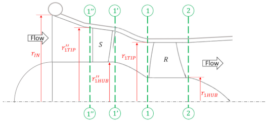
In order to define the preliminary shape of the meridional channel of the machine, further geometric data must be defined, based on authors’ experience (e.g., [19]) and statistical correlations (e.g., [17,20,21]): the runner hub to tip ratio is limited to 0.4 for the highest specific speed, a bulb/blade tip diameter ratio of 0.8 is chosen, and finally an axial velocity ratio of 2.0 from the turbine intake to the runner blade inlet section is adopted. With these assumptions, it is possible to obtain the first guess meridional channel of the machine, shown in Figure 1, while the main geometrical ratios are reported in Table 1.
For the evaluation of the flow angles, the net head and the reference diameter D1TIP are the design input and the flow coefficient φ and the head coefficient ψ are fixed by the criteria mentioned above. The rotational speed is determined from the value of ψ and the flow rate Q that the turbine can deliver is obtained from φ. The work coefficient can also be expressed as a function of the work exchange:
where is the peripheral speed at rotor inlet mean radius. The imposition of maximum efficiency condition sets null absolute tangential velocity component at the rotor exit (). From this expression, assuming the free vortex design condition, which imposes constant work exchange and constant axial velocity component along the spanwise direction, it is possible to determine the value of the tangential component of the absolute flow velocity at the rotor inlet, in function of the radius.
The distributor inlet flow angle is set equal to zero, due to the condition of axial symmetry of the flow coming from the intake, while the outlet flow angle is estimated, starting from the runner inlet flow angle, through expressions that combine the continuity equation and the angular momentum conservation equation between the sections 1’ and 1, shown in Figure 1. Once the flow angles have been identified, it is necessary to evaluate the vane and blade metallic angles suitable to realize the desired deflections.
For the distributor blade design, to limit their geometrical complexity and consequently the manufacturing costs, a simple circular arc camber is chosen. The linear stacking law of the blades profile is imposed on the leading edge, while to obtain the desired exit metallic angle value, the axial extension of the blade is suitably chosen. A first estimate procedure for the trailing edge inclination angle is provided in [19].
The thickness of the distributor blade is assumed constant for all sections and the value is determined by structural considerations. To improve the hydrodynamic performance of the blade, the leading edge is rounded, while the trailing edge is tapered and rounded. Based on all these considerations, the distributor blade is completely defined (Figure 2).
For the runner blade, based on axial chord limitation and moderate profile winding at the hub criteria, a four-blade configuration has been chosen. The runner blades are designed according to the radial equilibrium equations non-isentropic radial equilibrium (NISRE) and stacked on the center of gravity.
The Zweifel criterion [22], based on the evaluation of the aerodynamic load, was adopted for the definition of the pitch to chord ratio for the considered sections in the spanwise direction. The adoption of proper values of Zweifel coefficient, based on previous experience, ensures that the blade profiles can provide a load shape suitable for limiting losses and, on the other hand, that the value of the Thoma cavitation coefficient is able to ensure free cavitation operational conditions [23]. The profile maximum thickness and thickness distribution from hub to tip are assigned from previous successful realizations, after structural stress and vibrational analysis verification.
Once the shape of the blades in terms of camber and thickness laws is chosen, it is necessary to calculate the values of the blade angles, which determine the desired values of the flow angle for the different spanwise sections. To this aim, it is necessary to quantify the value of the flow deviation angle. This evaluation is performed for both stator and rotor blades by means of two-dimensional blade to blade calculations carried out with the Numeca FineTurbo solver [24]. According to the CFD results in terms of flow angles, the blade geometry of both vane and runner are thus modified to compensate the flow deviation angle. The desired flow angle is obtained after a few iterations of the presented procedure.
3. Turbine Analysis and Optimization
This preliminary geometry represents the starting point of an automated aerodynamic optimization procedure which employs several modules of the software Numeca Int, based on the parametric description of the turbine geometry, the systematic variation of the main design geometrical parameters in a reasonable range of variation, and finally the construction by Reynolds averaged Navier-Stokes (RANS) CFD 3D simulations of the corresponding wide database of performance through design of experiments (DoE) technique. Then, an artificial neural network (ANN) is employed to model a properly defined objective function, able to take into account the main target of design process: achievement of the reference net head, maximization of the internal efficiency, minimization of the cavitation zones, and a desired exit flow angle spanwise distribution with null exit swirling flow at the hub. After ANN training, the ANN is employed as a meta-model for the exploration of the optimization domain space by means of a genetic algorithm in order to find an optimum candidate solution, which has to be verified through a CFD calculation. This CFD result is inserted in the database to update the ANN training for the successive chosen number of optimization process iterations. The optimization procedure is summarized in Figure 3.
The design process and the subsequent optimization step are carried out at a fixed operating point, because, as anticipated, the machine is designed to work in nominal operating conditions (fixed values of flow and work coefficients).
3.1. Geometry Parameterization
The Numeca Autoblade module [24] was used for geometry parameterization. For the stator vanes, a simple Bezier curve for the description of the camber line is employed, while for the parameterization of the thickness law, a 5-parameter b-spline is adopted, keeping a constant thickness value with rounded leading edge and tapered trailing edge. The stacking law is assigned on the leading edge of the blade. For the parameterization of the rotor blades, a 5-point b-spline is adopted for the camber line, while a 5-parameter b-spline is used for the symmetrical thickness law, which allows the maximum thickness to be correctly located. The stacking law is assigned to the center of gravity of the rotor blade sections. The meridional channel is parameterized with a composite line that is a combination of straight lines and Bezier curves, with a total number of 9 control points both for hub and shroud lines. The definition of the three-dimensional shape of blades and vanes is obtained by employing 3 blade sections at the span values corresponding to 0, 0.5 and 1.
In order to reduce the number of geometrical parameters employed within the optimization procedure, some constraints have been introduced. For the meridional channel contour, no geometrical variations have been allowed, consisting in a fixed meridional channel geometry. For stator blades construction, given the constructional simplicity to be obtained, it was decided to maintain the same shape for the different sections, modifying the extension of the axial chord. In fact, considering Figure 2, it can be seen how the value of outlet metallic angle is a function of the extension of the arc of circumference and, consequently, of the value assumed by the axial chord. The law of camber and that of thickness are, instead, kept constant. On the contrary, for rotor blades, in order to allow the variation of the inlet and outlet metallic angles, the values of the tangential coordinates of the points that determine the camber law are free to vary, keeping unchanged the law of thicknesses along the blade. Therefore, since the sections used for parameterization are 3, there is a total of 18 free parameters (3 for the stator, 15 for the rotor).
3.2. Mesh Generation and Numerical Model
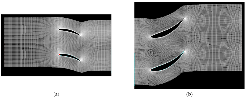
The simulated domain extends from the inlet section of the converging duct to the outlet section of the downstream diffuser, with a real axial extension of about 12 m. The Autogrid 5 software was used to generate the mesh, using a multi-block approach and choosing an O-4-H topology for the stator and rotor blocks (Figure 4) and a specific topology for the diffuser, capable of ensuring a good quality of the mesh also near the axis of the machine, downstream of the ogive. Given the large number of cases to be computed during the database generation, a stationary RANS approach was chosen. In addition, since the distance between the stator exit and rotor inlet sections is quite large, the mixing plane approach has been adopted to manage the passage of information from the stator frame to the rotor frame. The direction of the gravitational acceleration is imposed normal to the axis of the machine.
An analysis of the grid dependency was conducted by carrying out the calculation of the preliminary configuration geometry of the machine using meshes of different number of elements and taking the values of the total to total efficiency and of the net head as reference. Table 2 shows the results obtained from the analysis of the grid dependency on three different meshes.
Since the values of the reference quantities for the intermediate and fine grid are very close each other’s, the intermediate grid is used for all the simulations presented below. For this mesh, about 1 million elements is employed for the stator block, 2 million elements for the rotor block, and about 1.7 million elements for the block related to the diffuser. The discretization in space is based on a cell centered control volume approach, while a multi-stage Runge-Kutta scheme with local time stepping is adopted for time discretization, associated with multigrid technique [24].
Given the large number of simulations to be performed during the database generation, the simple but reliable turbulence model [25,26] proposed by Spalart-Allmaras [27] was chosen for the evaluation of the turbulence effects. The mesh first cell height is suitably chosen in order to ensure a value of below the unit.
For boundary conditions, at the inlet section, located at the inlet of the converging duct, the value of the mass flow rate is imposed, together with the values of the static temperature, the turbulent viscosity, and the flow angle. In particular, given the convergent inlet duct, the value of the flow meridional angle along the span direction has been imposed with a linear law interpolating between the null value, at the hub, and the value assigned by the slope of the converging duct near the shroud.
In the outlet section, the average value of the static pressure is assigned, determined from the hydrostatic head acting on the diffuser outlet section. Since the Numeca FineTurbo solver [24] employs a density based approach, it is necessary to use an artificial compressibility model for the solver. For the present case, the Hakimi model [28] was chosen, calibrating the typical model coefficients on the mean flow characteristic parameters.
3.3. Database Generation
For the turbine geometry optimization, as the number of variables is quite large, a 10X random sample has been chosen. In fact, other schemes would lead to a too expensive sampling step. Each parameter range has been split in five different values, and about 200 sample CFD calculations, chosen with a pseudo-random technique called “random among discrete levels”, have been employed. Each computation is run in serial (2 h on modern CPU), but the overall database generation has been split over several CPUs.
3.4. Objective Function and ANN Settings
The objective function for turbine geometry optimization process, to be minimized, is made up of several penalty terms:
For a generic quantity , each term is imposed in the form:
where is a weight factor, is the actual value of the considered quantity, is the imposed value, is a reference value for quantity variation normalization, and k is the exponent of the penalty term.
The term aims to ensure a net head equal to design condition. The term is inserted within global objective function in order to maximize the value of total to total efficiency, while the term addresses the constrain to keep the static pressure minimum value on suction side of the rotor blade above the vapor pressure. Finally, in order to keep the outlet absolute tangential velocity in a desired range, the terms and are introduced and controlled on three equally spaced span-wise sections.
In order to construct the approximate model for optimization process, FINE™/Design3D uses an artificial neural network. For the present case, a 10 hidden nodes with 2 layers was chosen for ANN topology, while 100,000 iterations with a converge level criteria equal to for learning by back-propagation of the errors scheme was set.
3.5. Optimization Results
Table 3 shows the overall performance of both the preliminary and the optimized turbine geometry, compared with design target values. From Table 3, it comes out that the preliminary configuration gives reasonable results, but the turbine performance should be improved to comply with the design targets and therefore a try and error iterative design procedure or the preferable optimization design procedure, as proposed in the present paper, should be applied.
In the third column, Table 3 reports the overall turbine performance of the optimized prototype. The most significant result is the achievement of the target value for the net head necessary to allow the target flow rate through the turbine. Consequently, head coefficient and nominal specific speed are achieved as well. The other important results are the improvement of total to total efficiency of about 1 point respective to the target design value and the substantial achievement of the expected static pressure recovery in the discharge turbine diffuser.
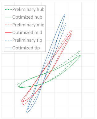
Figure 5 shows the shape of the blade profiles in the plane normal to the stacking axis of the rotor blade. The dotted line shows, using different colors, the shapes of the three sections considered (hub, midspan, and tip) in the preliminary configuration of the machine, while the solid lines show the corresponding shapes in the optimized configuration.
As can be seen, the optimization process entailed a modification of the stagger angle for the midspan section, keeping the deflection angles almost unchanged, while for the tip section, an increase in profile deflection and for the hub section a decrease in profile deflection respectively are observed.
As stated by Denton [29], a rational measure of losses in adiabatic thermodynamic transformations in turbomachinery is entropy creation. In fact, during an irreversible process, entropy is created, and its evaluation can be conveniently used to define a loss coefficient of the blade row. In addition, the use of the entropy is particularly convenient because unlike stagnation pressure and stagnation enthalpy, it does not depend on the reference frame (absolute or relative) and therefore can be used for both the stator and the rotor rows. In addition, the entropy that is created for example in the boundary layers of the blade or on the hub and shroud surfaces is transported in the flow and diffuses into the surrounding flow. Therefore, the evaluation of the entropy “concentration” in some characteristic sections of the machine allows estimating the global contribution of the loss sources. Figure 6 presents the normalized entropy color contours for preliminary (a) and optimized (b) configurations, calculated as:
The major extension of low normalized entropy areas for preliminary configuration denotes higher losses, which are reduced for the optimized configuration, showing a lower entropy increase mainly located in the blade wakes.
Although entropy is a quantity of considerable interest for the evaluation of the loss generation zones in turbomachinery [29], in the case of hydraulic machines, it is more common to represent the total pressure loss coefficient as a measure of the areas affected by localized energy losses, defined as, for the rotor blade, as:
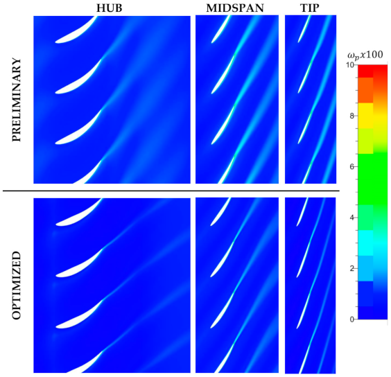
where is the reference relative total pressure value located in a upstream section, is the local relative total pressure value, and is the reference dynamic pressure. Figure 7 shows the relative total pressure loss coefficient contours for three blade-to-blade sections, located at 0.05, 0.5, and 0.95 blade span for the original and the optimized cases.
Comparing the preliminary and the optimized case results, the reduction of the areas characterized by high values of the total pressure loss coefficient for the optimized case for all the sections considered is evident, which justifies the higher value of the total to total efficiency.
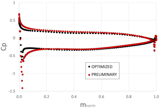
Figure 8 shows the distributions of the calculated pressure coefficient defined as:
for three spanwise sections of the rotor blade, at root, mid-span, and tip of the blade. This coefficient, when the local pressure assumes the value of the vapor pressure, provides the cavitation coefficient in condition of incipient cavitation:
Figure 8 shows that the objective of obtaining a constant aerodynamic loading over the blade profile from hub to tip has been achieved at least from the 50% of the chord onwards.
This is one of the fundamental design criteria that leads to the best efficiency for the rotor power conversion and also determines the best cavitation performance for the blades. Assuming, from the diagram, a critical value of , the critical coefficient assumes the value of which is in line with the values typical of best realizations for this large specific speed. In addition, taking for example the pressure coefficient diagrams for the midspan section in the preliminary and optimized case, presented in Figure 9, it is evident that the modification of the geometry of the rotor blades has led to a reduction of the area, placed near the leading edge of the blade, characterized by a low value of the pressure coefficient and therefore at risk of cavitation.
By comparing the static pressure coefficient color contours in the blade-to-blade plane at midspan section of the rotor blade for the preliminary and optimized geometry, presented in Figure 10, it can be seen how the stagger angle modification carried out by the optimization procedure allows re-establishing the correct flow incidence angle, as deduced from the correct position of the stagnation point and the reduction of both maximum and minimum pressure coefficient extensions closed to the leading edge for the optimized case.
3.6. Turbine Off Design Operation
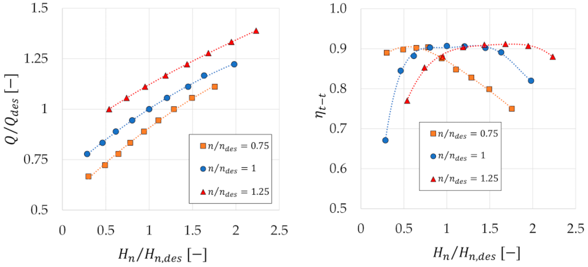
In order to assess the behavior of the machine for different net heads and rotational speeds, several numerical simulations have been carried out. In Figure 11, the characteristic curves of the machine, normalized with respect to design values, are presented. More specifically, the figure on the left shows the relationship between normalized volume flow rate and net head, while the figure on the right shows the total to total efficiency as a function of normalized net head, for three different rotational speeds (the nominal one, equal to 200 rpm, and for a higher and a lower rotational speed).
The left figure shows the characteristic curve, direct relation between net head and volume flow rate for the turbine. Since the vane and blade rows are not adjustable, there is only one curve for each rotational speed, and if the net head changes (and consequently the mass flow rate), the turbine total to total efficiency value decreases due to the not optimal incidence of the flow on the blades. For this reason, for net heads lower than the nominal one, the maximum efficiency can be obtained by reducing the rotational speed, while for net heads higher than the nominal one, the maximum efficiency is obtained by increasing the rotational speed. According to the hydraulic turbine similarity theory, the optimal solution can be obtained by modifying the rotational speed proportionally to , in such a way that a constant value of the load coefficient ψ, equal to the design value, is obtained. The application of this relation between net head and rotational speed ensures the correct flow incidence at the rotor blade inlet and the absolute circumferential velocity null condition at the exit, and, therefore, allows obtaining high values of the turbine efficiency, as confirmed by CFD results.
The variation of the rotational speed as the net head changes is made possible, as previously observed, by the adoption of a synchronous permanent magnet electric generator and an inverter system.
4. Conclusions
Currently, the wide low head hydro potential for renewable energy conversion, which is intrinsically environmentally sustainable, may become interesting also from the economical point of view if low cost, highly efficient energy conversion turbines become accessible. Because of the low specific energy available and therefore the inherent large dimensions of the energy conversion machines to be employed, the development of turbines of simplified design and low cost manufacturing characteristics, without efficiency reduction effects, is mandatory. The paper has reported a rational and successful example of optimization design of a new simplified hydraulic turbine for low heads applications, cost effective and with large efficiency.
The starting point is a preliminary design based on sound experience, best practices for hydraulic turbines, and use of classical design rules and correlations for axial machines. Several physical constraints are fixed in relation to the concept of maximum simplification without loss increase. Among others, the concepts of flow acceleration in both distributor and rotor and in meridional channels up to the runner exit, limited profile aerodynamic loading equally distributed, along the span-wise direction are applied which determine the meridional flow path, number of blades and rotor blade stream-wise extension.
From the physical point of view, with the given geometrical and operating constraints, once the inlet and exit boundary conditions (flow rate at inlet and static pressure at exit) are fixed, the optimization process shall determine the missing geometrical parameters (i.e., vane and rotor blade exit angles, as well as blade inlet angles) which are capable of guaranteeing achievement of the targeted fundamental parameters, which are the rated net head, the maximum as possible total to total efficiency, the limitation on the absolute flow angle at the rotor exit, and the maximum free of cavitation blade extension.
From the analysis of the results, it comes out that, under fixed design and operating conditions, the optimization process was able to update the preliminary design geometry to achieve the targeted head coefficient with an increase of the total to total efficiency for the complete turbine, a targeted limited absolute flow swirl at the exit, and a cavitation coefficient in line with the statistics for the best realizations of such high specific speed turbines.
This type of turbine with fixed geometry is not suitable for regulating the flow rate and therefore the output power at constant net head. In case of variation of the available net head, the flow rate varies according to the turbine characteristic curve and, if the rotational speed is kept constant, the flow velocity triangles change respective to the nominal ones and the turbine hydraulic efficiency drops rapidly. In this paper, it has been shown, by means of several CFD simulations, that the turbine hydraulic efficiency can be restored by adapting the rotational speed to the net head variation in agreement with the similitude theory. This concept can be implemented in practice by employing a permanent magnet synchronous generator and an electronic frequency regulator.
Author Contributions
Each author contributed to different aspects of the paper; namely, M.U. and P.Z. contributed to the conceptualization of the hydraulic turbine design, R.F. contributed with the conceptualization of industrial aspects of the hydraulic turbine design. D.B. contributed to paper organization, hydraulic turbine design, CFD simulation, design optimization, result analysis, and paper preparation. All authors have read and agreed to the published version of the manuscript.
Funding
This research has been funded by a research contract of SEMI Industrial with Unige on Advanced design of hydraulic turbines.
Data Availability Statement
Not applicable.
Conflicts of Interest
The authors declare no conflict of interest.
Nomenclature
| Absolute velocity, blade chord | Subscripts | ||
| Pressure coefficient | Referred to stator inlet section | ||
| Diameter | Referred to stator outlet section | ||
| Generic quantity | Referred to rotor inlet section | ||
| Gravitational acceleration | Referred to rotor outlet section | ||
| Head due to kinetic energy losses | Ambient | ||
| Net head | Constructive, critical | ||
| Suction head | Dynamic | ||
| Penalty function exponent | Reference design value | ||
| Draft length | Referred to hub | ||
| Normalized axial coordinate | Inlet | ||
| Rotational speed | Maximizing objective function | ||
| Specific speed | At meanline | ||
| Static pressure | Minimizing objective function | ||
| Electric power | Reference | ||
| Optimization penalty function | Referred to tip | ||
| Volumetric flow rate | Total relative | ||
| Radius | Vapor | ||
| Curvature radius | Axial | ||
| Entropy | Tangential | ||
| Blade thickness | |||
| Static temperature | |||
| Peripheral speed | |||
| Work exchange | |||
| Penalty function weight factor | |||
| Non dimensional wall coordinate | |||
| Greeks | Acronyms | ||
| Absolute flow angle | Artificial neural network | ||
| Density | Computational Fluid Dynamics | ||
| Thoma cavitation coefficient | Design of experiments | ||
| Flow coefficient | Non-isentropic radial equilibrium | ||
| Work coefficient | Net positive suction head | ||
| Total to total efficiency | Reynolds average Navier–Stokes | ||
| Mechanical and electric efficiency | |||
References
- REN21. Renewables 2018 Global Status Report; REN21: Paris, France, 2018; ISBN 978-3-9818911-3-3M. [Google Scholar]
- Kılkış, S.; Krajačić, G.; Duić, N.; Rosen, M.A.; Al-Nimr, M. Advances in integration of energy, water and environment systems towards climate neutrality for sustainable development. Energy Convers. Manag. 2020, 225, 113410. [Google Scholar] [CrossRef]
- Barbarelli, S.; Castiglione, T.; Florio, G.; Scornaienchi, N.M.; Lo Zupone, G. Computational Fluid Dynamic Analysis of the External Rotor Supporting the Design of a Tidal Kinetic Turbine Prototype. J. Sustain. Dev. Energy Water Environ. Syst. 2017, 5, 332–344. [Google Scholar] [CrossRef] [Green Version]
- Mosbahi, M.; Ayadi, A.; Chouaibi, Y.; Driss, Y.; Tucciarelli, T. Performance improvement of a novel combined water turbine. Energy Convers. Manag. 2020, 205, 112473. [Google Scholar] [CrossRef]
- Voith Website. Available online: http://voith.com/corp-en/hydropower-components/streamdiver.html (accessed on 8 October 2019).
- Andritz Website. Available online: https://www.andritz.com/hy-hydromatrix (accessed on 8 October 2019).
- Hoghooghi, H.; Durali, M.; Kashef, A. A new low-cost swirler for axial micro hydro turbines of low head potential. Renew. Energy 2018, 128, 375–390. [Google Scholar] [CrossRef]
- Borkowski, D.; Węgiel, M.; Ocłoń, P.; Węgiel, T. CFD model and experimental verification of water turbine integrated with electrical generator. Energy 2019, 185, 875–883. [Google Scholar] [CrossRef]
- Vagnoni, E.; Andolfatto, L.; Richard, S.; Münch-Alligné, C.; Avellan, F. Hydraulic performance evaluation of a micro-turbine with counter rotating runners by experimental investigation and numerical simulation. Renew. Energy 2018, 126, 943–953. [Google Scholar] [CrossRef] [Green Version]
- Barsi, D.; Ubaldi, M.; Zunino, P.; Fink, R. A new compact hydraulic propeller turbine for low heads. In Proceedings of the ASEE19 International Conference on Advances in Energy Systems and Environmental Engineering, Wroclaw, Poland, 9–12 June 2019. [Google Scholar]
- Schleicher, W.C.; Oztekin, A. Hydraulic design and optimization of a modular pump-turbine runner. Energy Convers. Manag. 2015, 93, 388–398. [Google Scholar] [CrossRef] [Green Version]
- Barsi, D.; Perrone, A.; Ratto, L.; Simoni, D.; Zunino, P. Radial inflow turbine design through Multidisciplinary optimization technique. In Proceedings of the ASME Turbo Expo 2015: Turbine Technical Conference and Exposition GT2015, Montreal, QC, Canada, 15–19 June 2015. [Google Scholar]
- Perrone, A.; Ratto, L.; Ricci, G.; Satta, F.; Zunino, P. Multi-Disciplinary Optimization of a Centrifugal Compressor for Micro-Turbine Applications. In Proceedings of the ASME Turbo Expo 2016: Turbine Technical Conference and Exposition GT2016, Seoul, Korea, 13–17 June 2016. [Google Scholar]
- Barsi, D.; Perrone, A.; Qu, Y.; Ratto, L.; Ricci, G.; Sergeev, V.; Zunino, P. Compressor and Turbine Multidisciplinary Design for Highly Efficient Micro-gas Turbine. J. Therm. Sci. 2018, 27, 259–269. [Google Scholar] [CrossRef]
- Barsi, D.; Costa, C.; Satta, F.; Zunino, P.; Busi, A.; Ghio, R.; Raffaeli, C.; Sabattini, A. Design of a Mini Combined Heat and Power Cycle for Naval Applications. J. Sustain. Dev. Energy Water Environ. Syst. 2020, 8, 281–292. [Google Scholar] [CrossRef]
- Thoma, D. Verhalten einer Kreiselpumpe beim Betrieb im Hohlzog. Bereich Z. Ver. Dtsch. Ing. 1937, 81, 972. [Google Scholar]
- De Siervo, F.; De Leva, F. Modern Trends in Selecting and Designing Kaplan Turbines. Water Power Dam Constr. 1977, 30, 32–58. [Google Scholar]
- Sovran, G.; Klomp, E.D. Experimentally Determined Optimum Geometries for Rectilinear Diffusers with Rectangular Conical or Annular Cross-Section, Fluid Mechanics of Internal Flow; Sovran, G., Ed.; Elsevier: Amsterdam, The Netherlands, 1967; pp. 270–319. [Google Scholar]
- Satta, A.; Ubaldi, M.; Zunino, P. Design of Axial Turbines for Mini-Hydro Plants, ASME. In Proceedings of the Fourth International Symposium on Hydro Power Fluid Machinery-FED, Beijing, China, 24–27 November 2008; Volume 43, pp. 29–36. [Google Scholar]
- Lugaresi, A.; Massa, A. Kaplan turbines: Design trends in the last decade. Water Power Dam Constr. 1988, 40, 12–17. [Google Scholar]
- Schweiger, F.; Gregori, J. Developments in the design of Kaplan turbines. Water Power Dam Constr. 1987, 39, 16–20. [Google Scholar]
- Dick, E. Fundamentals of Turbomachines; Springer: New York, NY, USA, 2015. [Google Scholar] [CrossRef]
- Ceravola, O.; Ubaldi, M.; Zunino, P.; Satta, A. Ecoulement dans une turbine Kaplan: Comparison entre calcul théorique, mesures de vitesse et observation de la cavitation. Houille Blanche 1982, 7, 579–587. [Google Scholar] [CrossRef] [Green Version]
- NUMECA. User Manuals. Academic R&D license; NUMECA: Brussel, Belgium, 2019. [Google Scholar]
- Derakhshan, S.H.; Mostafavi, A. Optimization of GAMM Francis Turbine Runner. Zenodo 2011. [Google Scholar] [CrossRef]
- Borkowski, D.; Węgiel, M.; Ocłoñ, P.; Węgiel, T. Simulation of water turbine integrated with electrical generator. MATEC Web. Conf. 2018, 240, 05002. [Google Scholar] [CrossRef]
- Spalart, P.R.; Allmaras, S.R. A One Equation Turbulence Model for Aerodynamic Flows; AIAA 92-0439; AIIA: Reston, VA, USA, 1992. [Google Scholar]
- Hakimi, N. Preconditioning Methods for Time Dependent Navier-Stokes Equations. Ph.D. Thesis, Dept of Fluid Mechanics, Vrike University, Brussel, Belgium, 1997. [Google Scholar]
- Denton, J.D. Loss mechanisms in turbomachines. Am. Soc. Mech. Eng. 1993, 78897, V002T14A001. [Google Scholar]
Figure 1.
Turbine meridional flow path and control sections.

Figure 2.
Geometry of the stator blades and details of the vane trailing edge.

Figure 3.
Flowchart of the optimization procedure.

Figure 4.
Blade to blade mesh for stator (a) and rotor (b) blades.

Figure 5.
Preliminary and optimized blade profile for different spanwise sections.

Figure 6.
Preliminary (a) and optimized (b) normalized entropy contours

Figure 7.
Pressure loss coefficient distributions for preliminary and optimized configurations.

Figure 8.
Pressure coefficient distributions for optimized configuration.

Figure 9.
Pressure coefficient distributions for preliminary and optimized configurations at midspan.
Figure 9.
Pressure coefficient distributions for preliminary and optimized configurations at midspan.

Figure 10.
Blade-to-blade pressure coefficient contours for preliminary (a) and optimized (b) configurations at midspan.
Figure 10.
Blade-to-blade pressure coefficient contours for preliminary (a) and optimized (b) configurations at midspan.

Figure 11.
Normalized characteristic curves for different rotational speeds.


Table 1.
Turbine main geometrical ratios.
| Geometrical Ratio | Value |
|---|---|
| 1.5 | |
| 0.4 | |
| 0.7 | |
| 1.2 |
Table 2.
Grid dependency results.
| Grid 1 | Grid 2 | Grid 3 | |
|---|---|---|---|
| Elements (millions) | 2.9 | 4.7 | 7.3 |
| (m) | 4.89 | 5.02 | 5.04 |
| (-) | 0.861 | 0.864 | 0.865 |
Table 3.
Propeller turbine main operating parameters for preliminary and optimized configurations.
| Operating Parameter | Preliminary Configuration Results | Optimized Configuration Results | Design Target |
|---|---|---|---|
| 178 | 212 | 212 | |
| φ (-) | 0.324 | 0.324 | 0.324 |
| ψ (-) | 0.399 | 0.318 | 0.318 |
| 0.864 | 0.913 | 0.900 | |
| Without diffuser | 0.942 | 0.940 |
Publisher’s Note: MDPI stays neutral with regard to jurisdictional claims in published maps and institutional affiliations. |
© 2021 by the authors. Licensee MDPI, Basel, Switzerland. This article is an open access article distributed under the terms and conditions of the Creative Commons Attribution (CC BY) license (http://creativecommons.org/licenses/by/4.0/).
Share and Cite
MDPI and ACS Style
Barsi, D.; Ubaldi, M.; Zunino, P.; Fink, R. Optimized Design of a Novel Hydraulic Propeller Turbine for Low Heads. Designs 2021, 5, 20. https://0-doi-org.brum.beds.ac.uk/10.3390/designs5010020
AMA Style
Barsi D, Ubaldi M, Zunino P, Fink R. Optimized Design of a Novel Hydraulic Propeller Turbine for Low Heads. Designs. 2021; 5(1):20. https://0-doi-org.brum.beds.ac.uk/10.3390/designs5010020
Chicago/Turabian StyleBarsi, Dario, Marina Ubaldi, Pietro Zunino, and Robert Fink. 2021. "Optimized Design of a Novel Hydraulic Propeller Turbine for Low Heads" Designs 5, no. 1: 20. https://0-doi-org.brum.beds.ac.uk/10.3390/designs5010020