
Crashworthiness Performance of Aluminium, GFRP and Hybrid Aluminium/GFRP Circular Tubes under Quasi-Static and Dynamic Axial Loading Conditions: A Comparative Experimental Study


Abstract
:1. Introduction
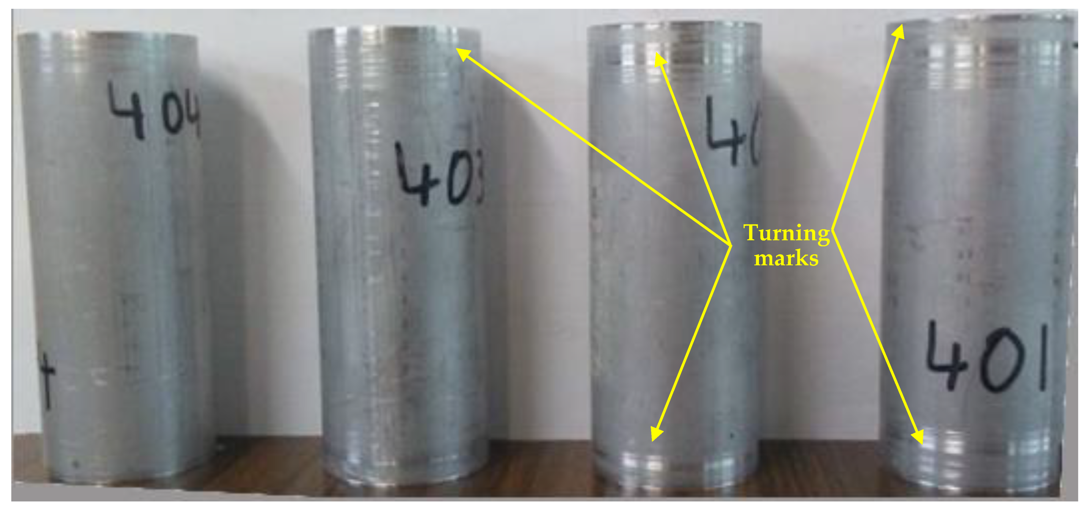
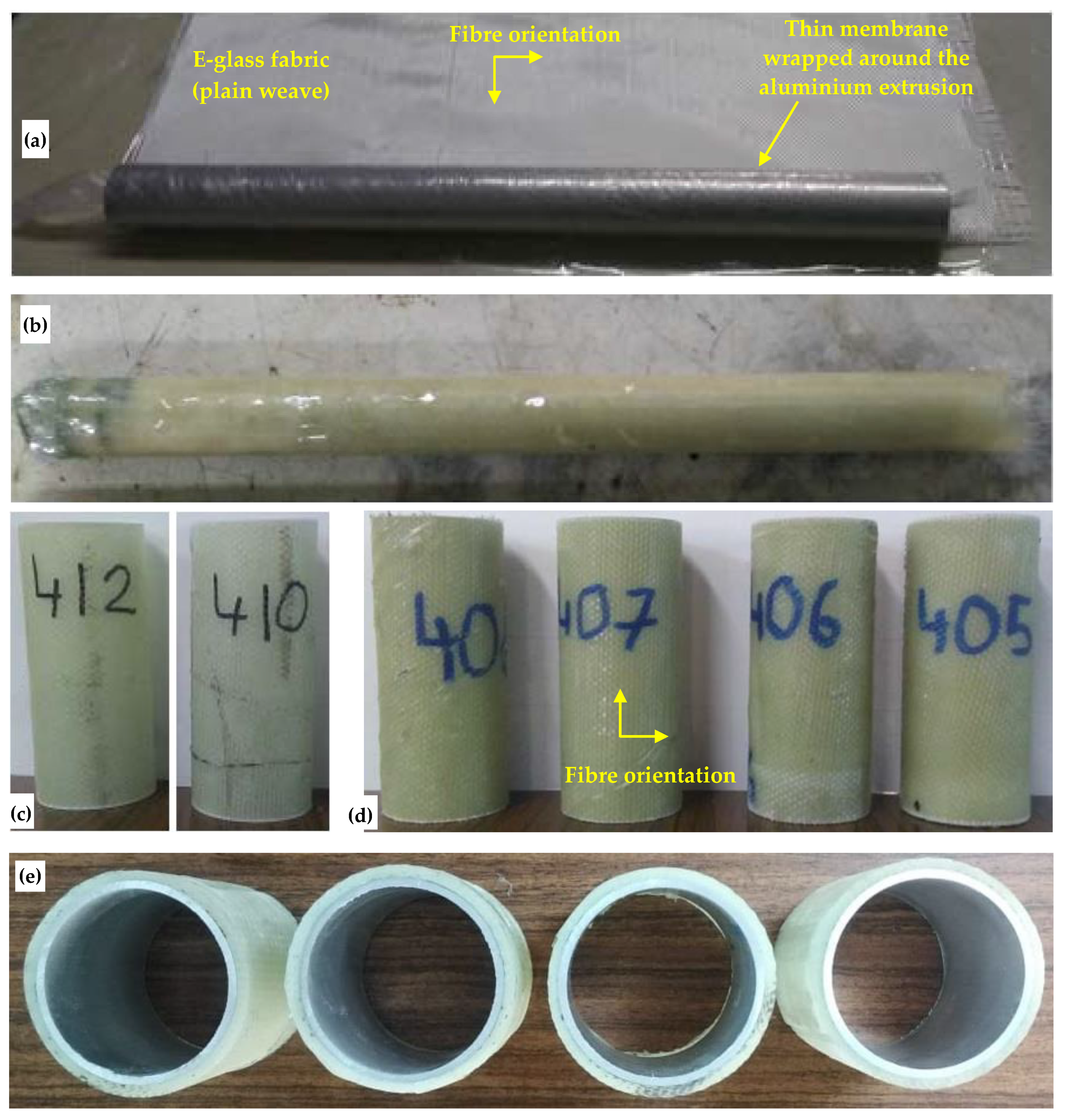
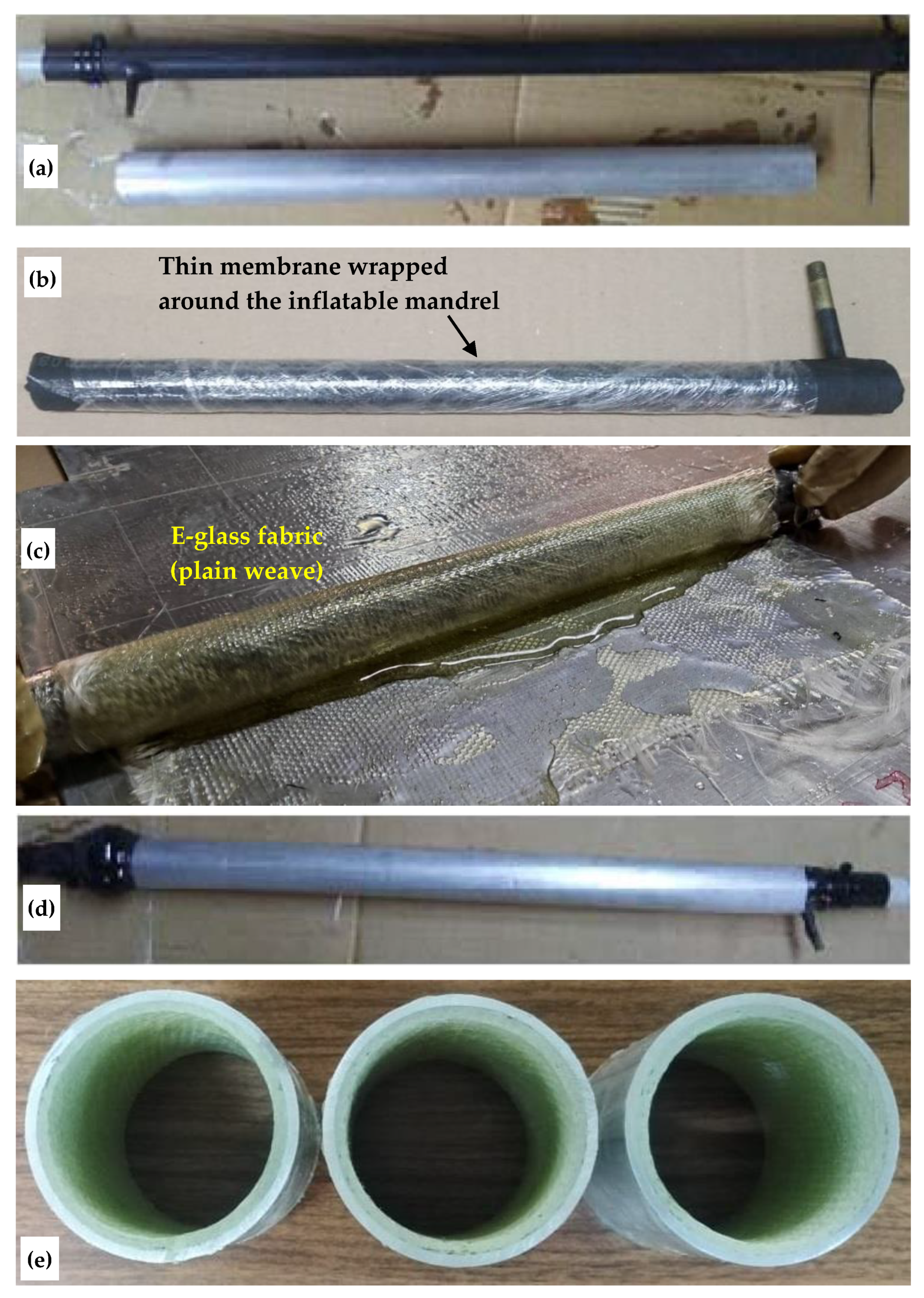
2. Specimens
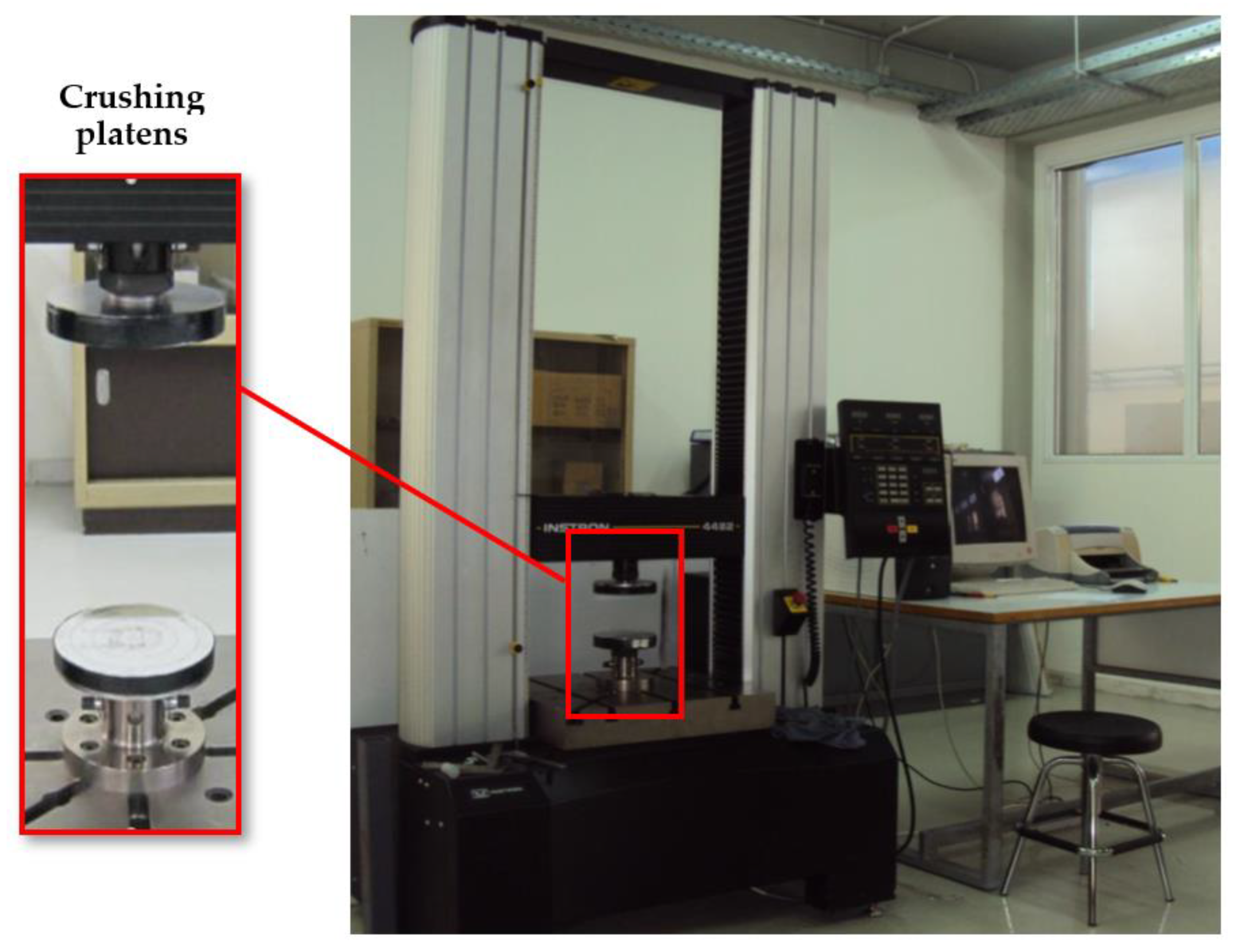
3. Test Set-Up
4. Crashworthiness Parameters
- Initial peak force (IPF) is defined as the first force peak in the force–displacement curve. The displacement δ1 corresponds to IPF and marks the initial wall buckling of the tube and the beginning of the energy dissipation process.
- Fmax is the maximum force achieved during the test. In the case of uniform non-triggered thin-walled tubes (i.e., non-tapered tubes with constant wall thickness) under quasi-static axial crushing conditions, Fmax usually coincides with IPF.
- Energy absorption (EA) is the non-recoverable energy during the test and corresponds to the area under the force–displacement curve, from δ1 until the displacement that marks the beginning of the densification region (δ2):where F is the reaction force of the structure at any δ. The elastic energy is usually negligible compared to EA, therefore, the lower limit of the integral is very often replaced with zero in such cases.
- Mean crushing force (MCF) is defined as the ratio of the EA and the displacement from δ1 until δ2:in the cases where there is no densification region and δ1→0, the denominator δ2 − δ1 can be replaced with the total crushing displacement (δT). MCF is a crashworthiness parameter that allows comparisons among the energy absorption ability of structures that have been crushed at different δTs.
- Specific energy absorption (SEA) is defined as the EA over the specimen mass swept by the crushing platen (i.e., δT). The expression for uniform tubes of multiple layers from different materials is given below:where ρi and Ai are the material density and the cross-sectional area of each layer, respectively. SEA is an important design parameter in applications where the weight of the structure is essential.
- Crush force efficiency (CFE) is defined as the percentage ratio of MCF over Fmax:If CFE reaches 100% the curve between δ1 and δ2 becomes a straight line parallel to the displacement axis (Figure 7) and the structure demonstrates ideal crashworthiness behaviour.
5. Results and Discussion
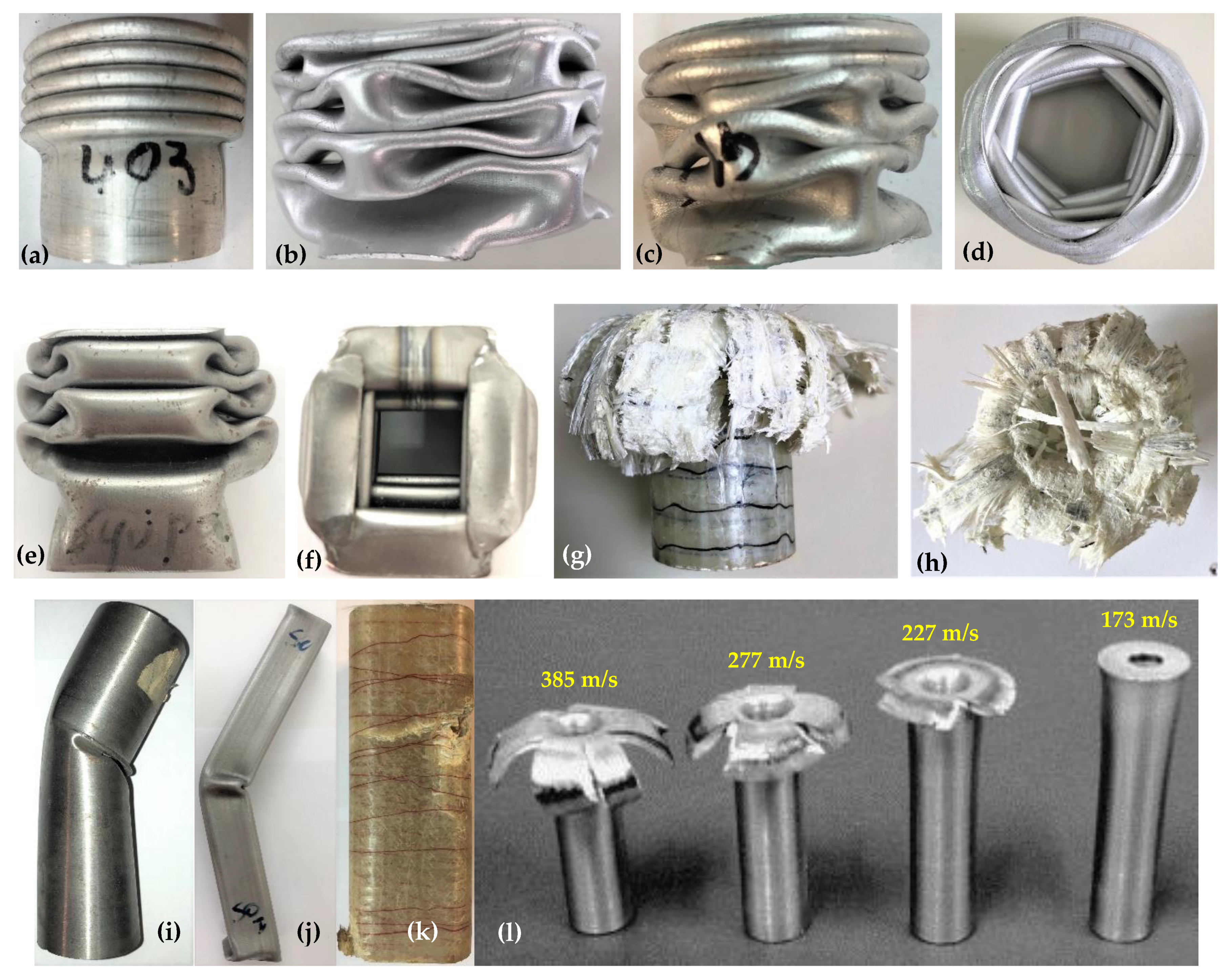
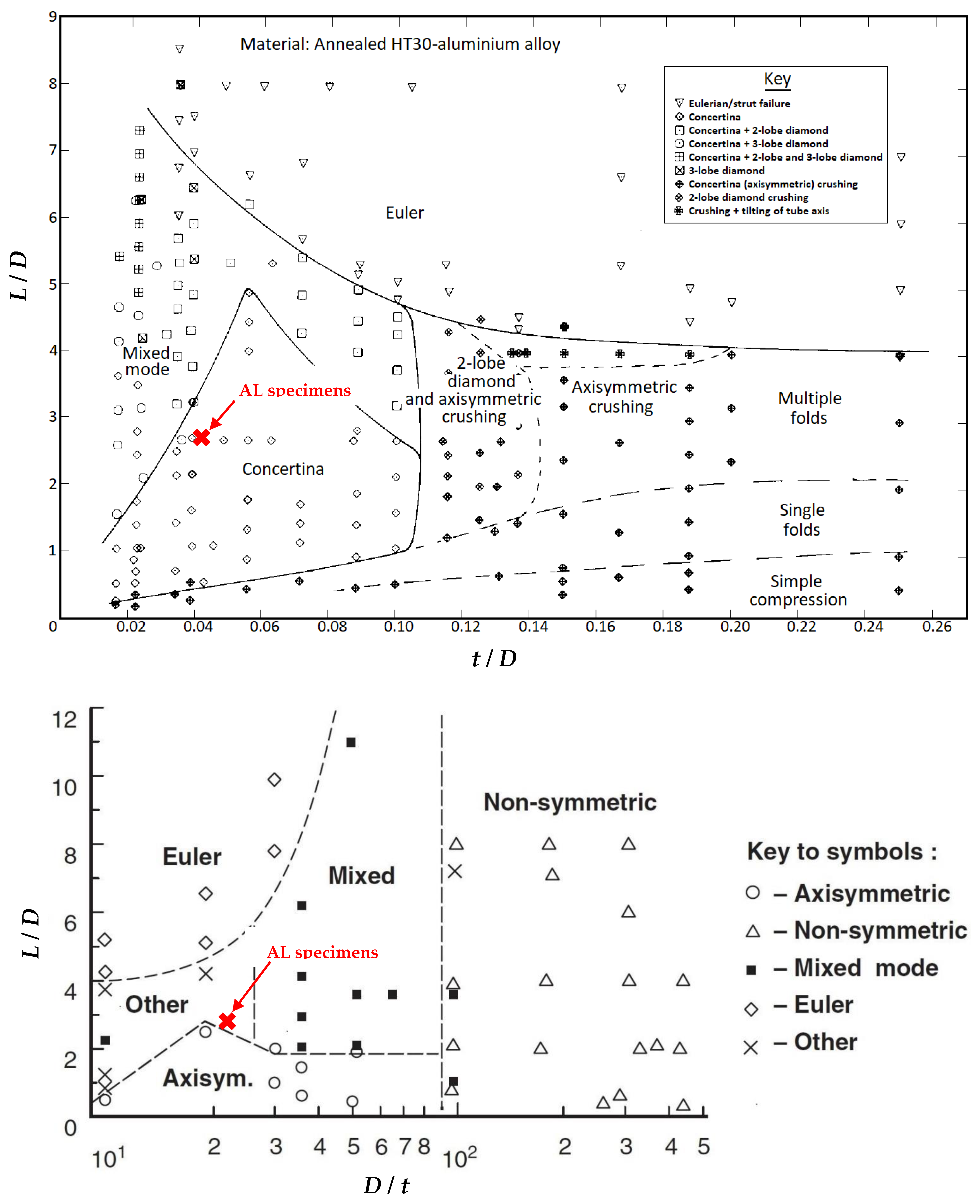
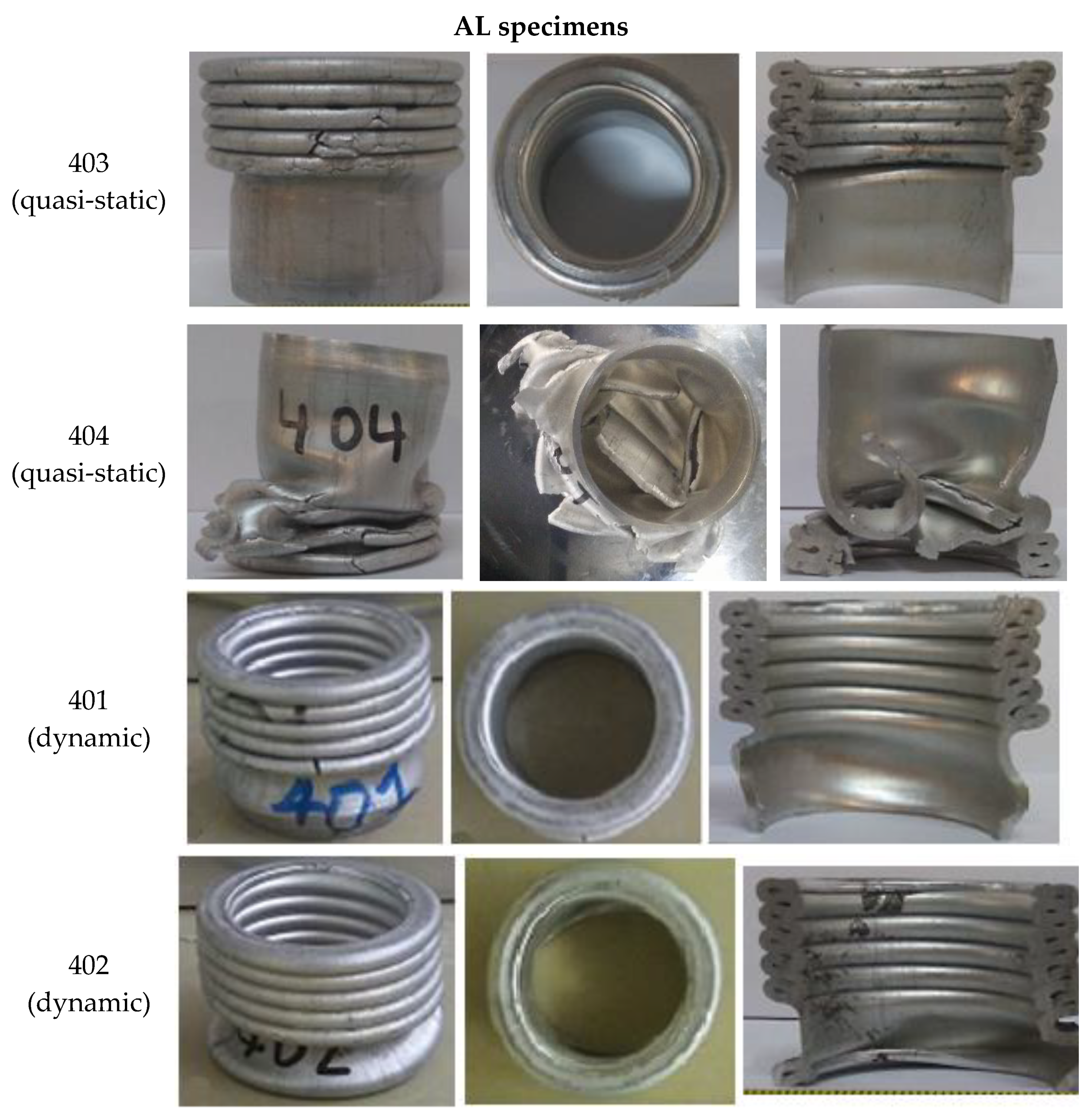
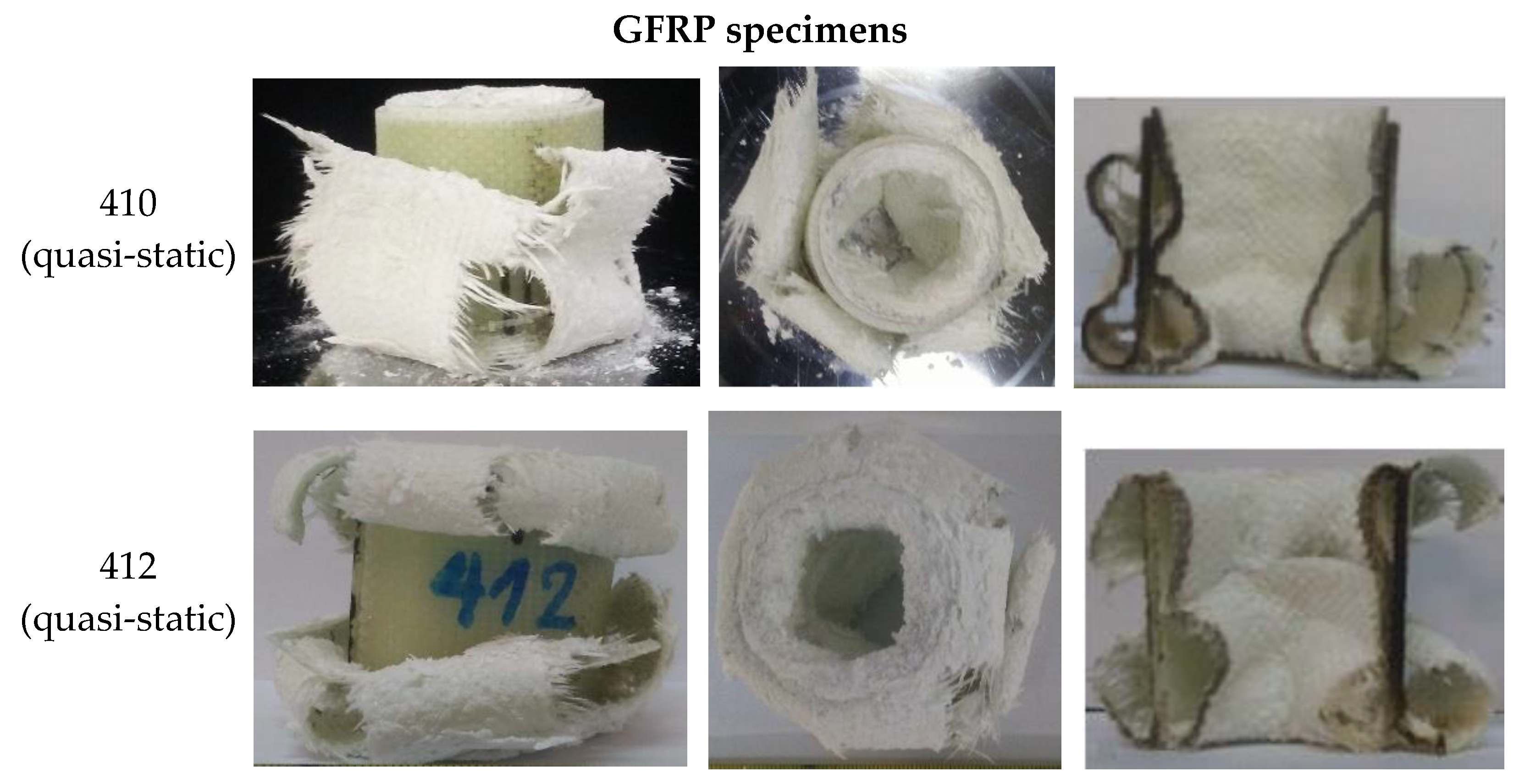
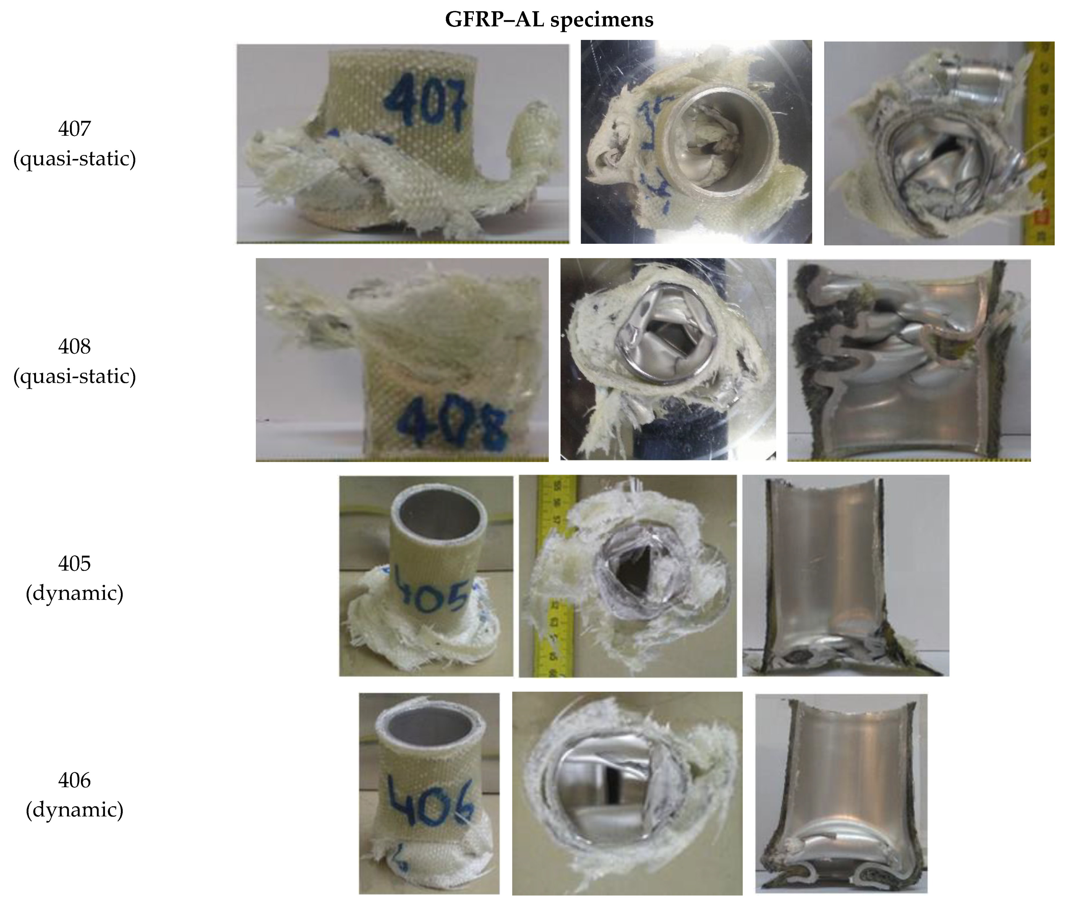
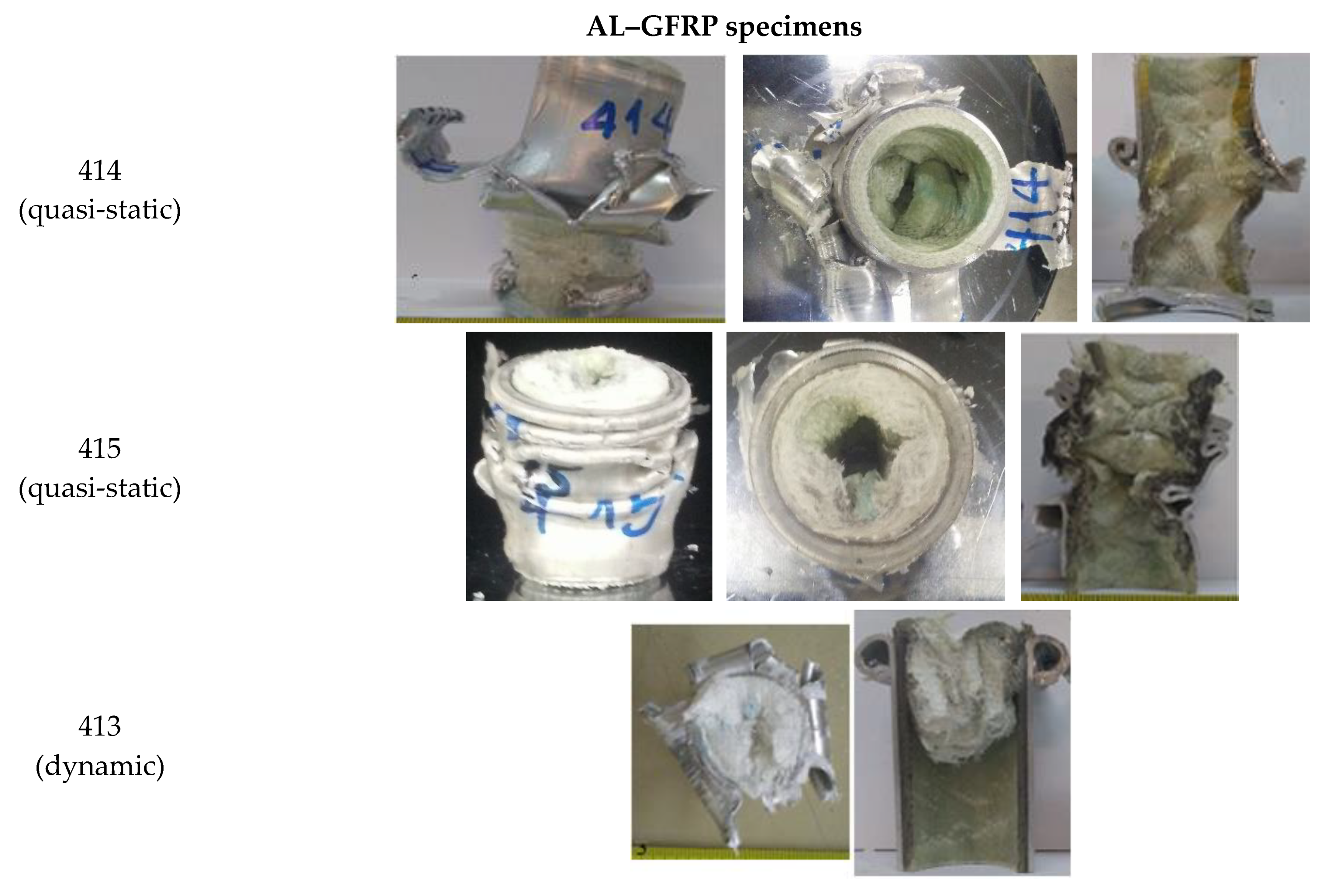
5.1. Collapse Patterns
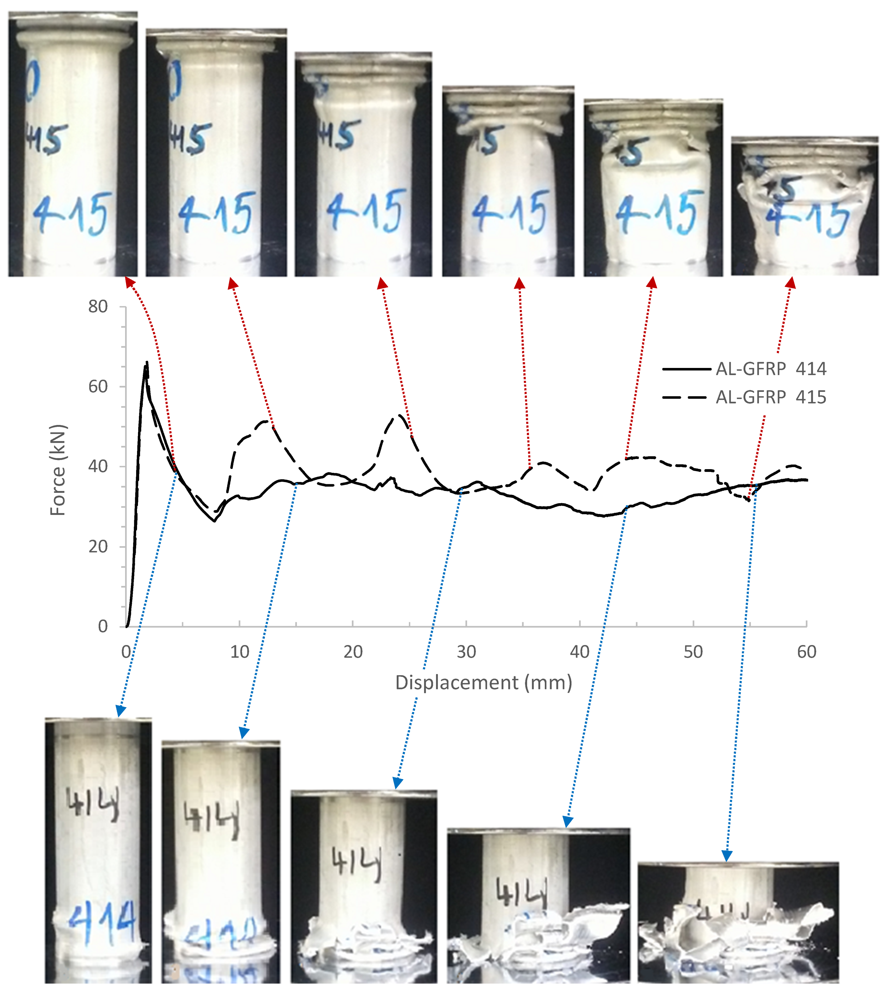
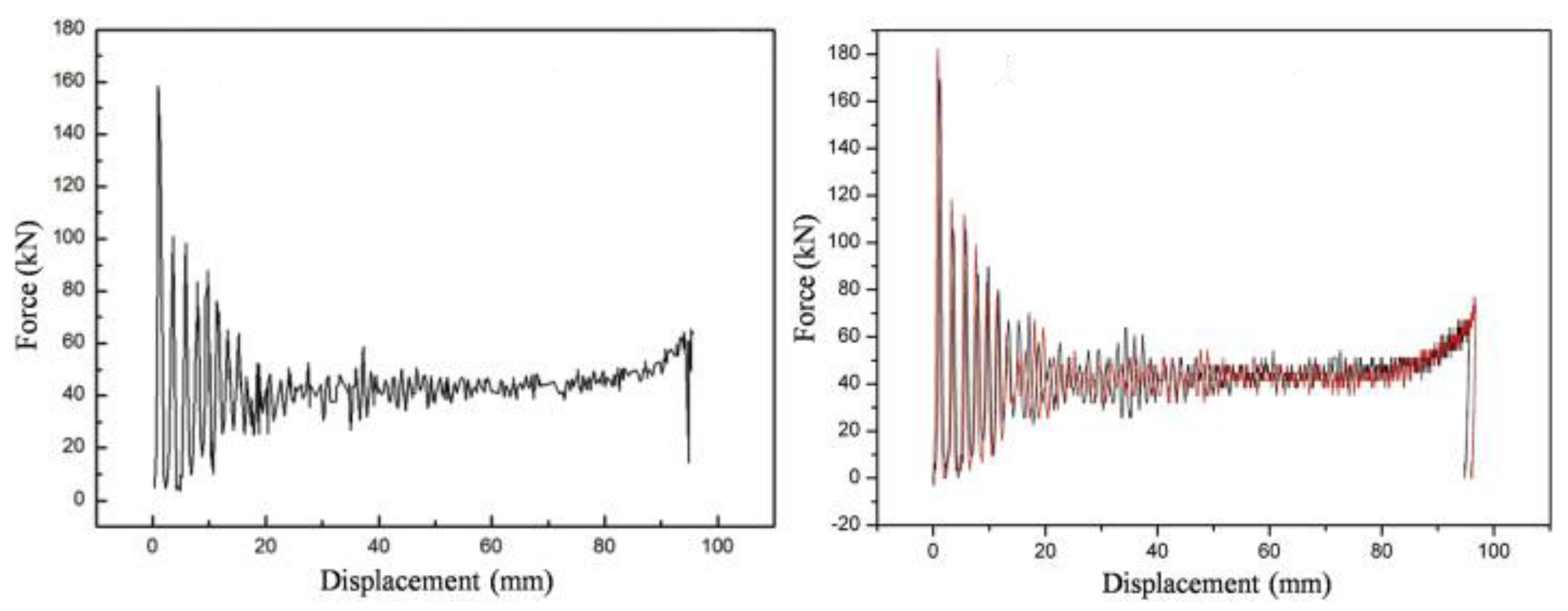
5.2. Force−Displacement Curves
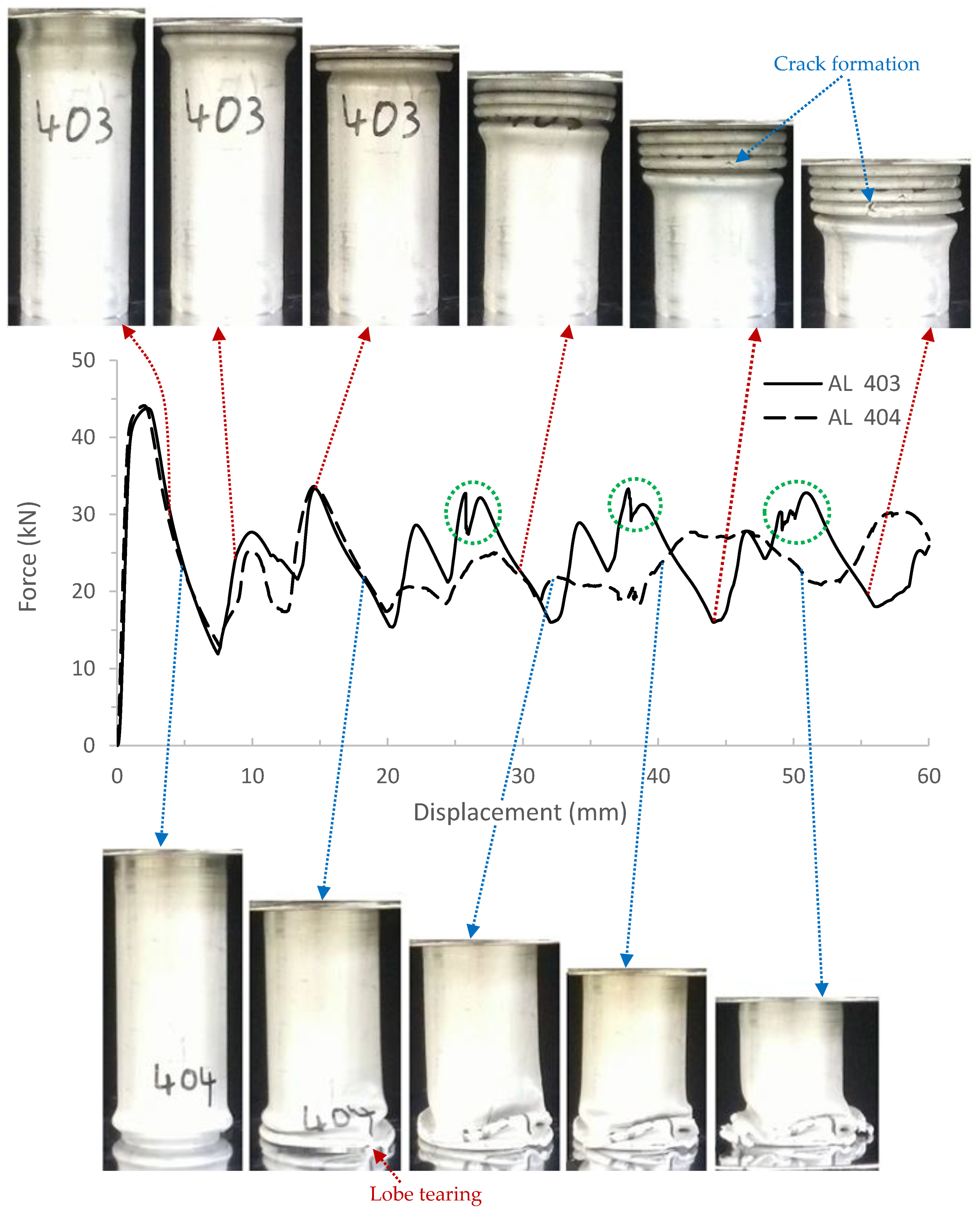
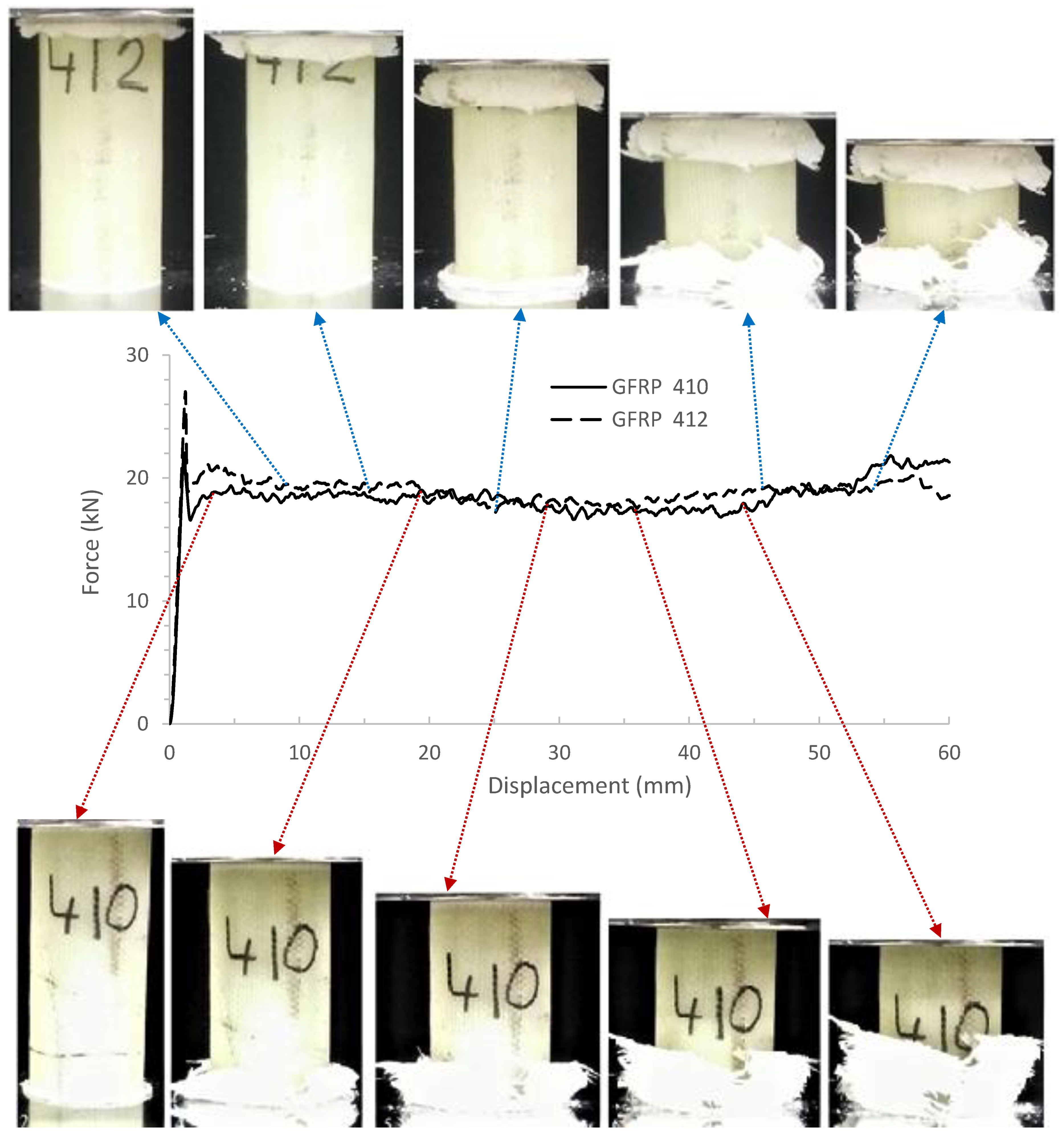
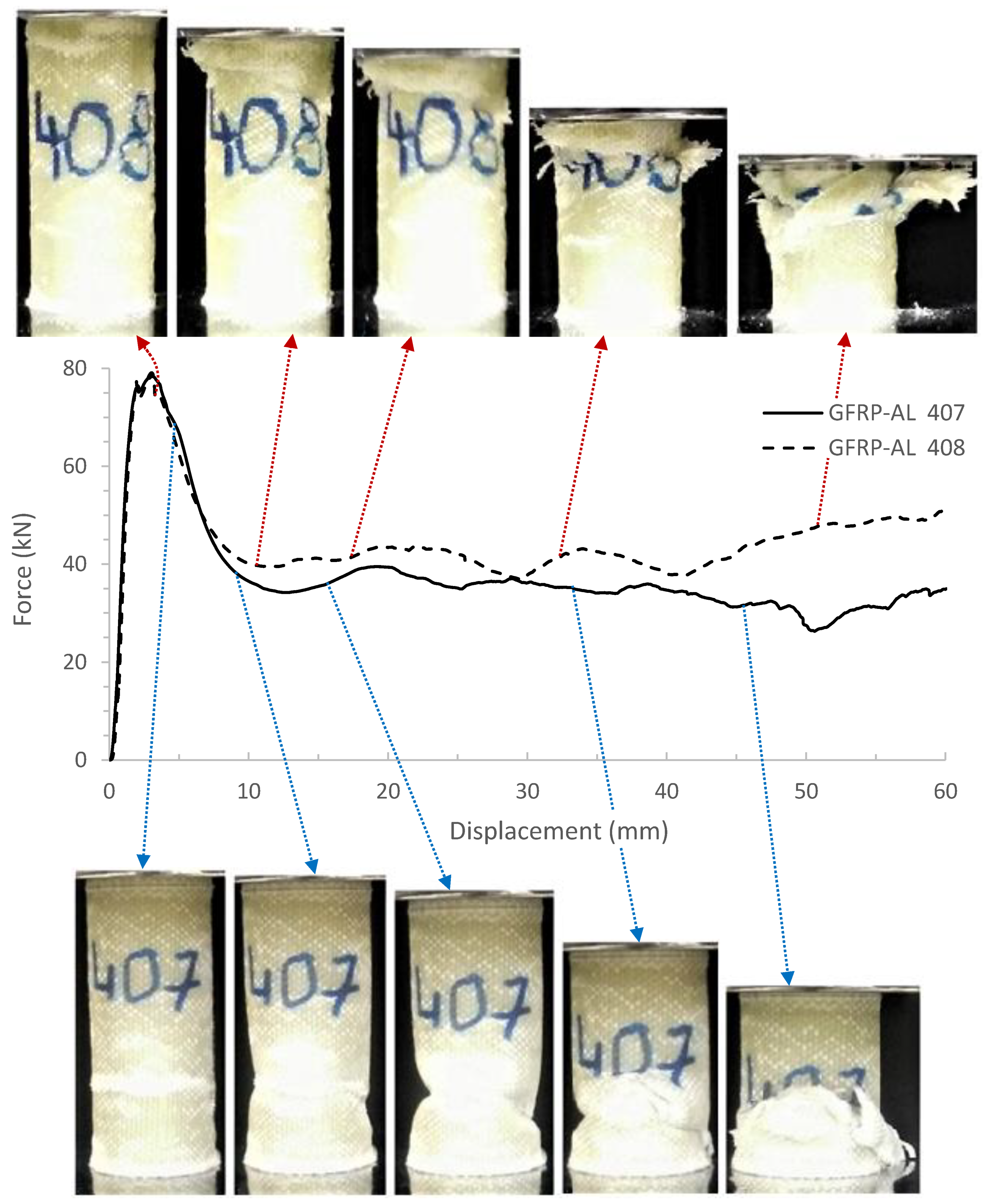
5.2.1. Quasi-Static Tests
5.2.2. Dynamic Tests
5.3. Crashworthiness Parameters
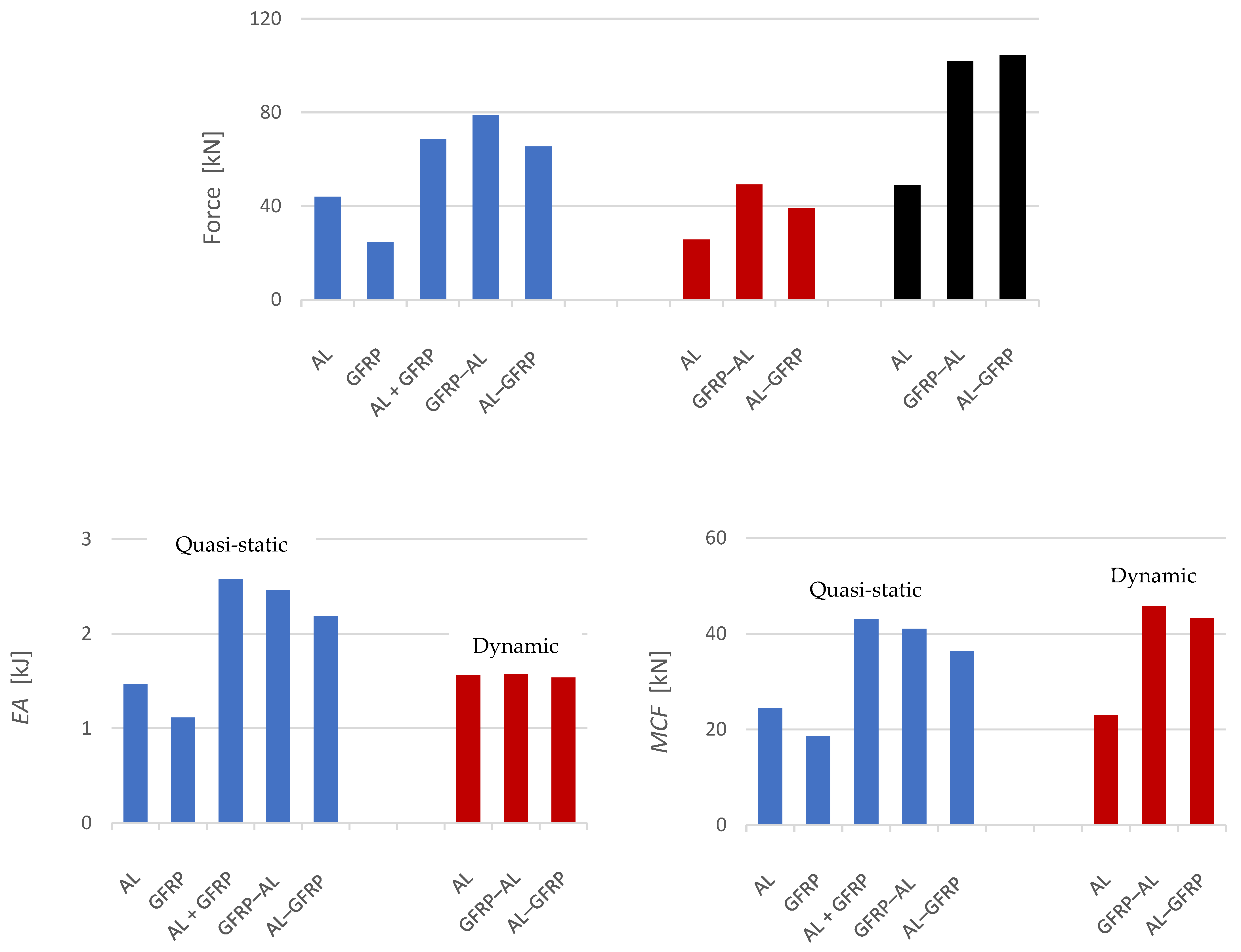
5.3.1. Initial Peak Force and Maximum Force
5.3.2. Energy Absorption
5.3.3. Mean Crushing Force
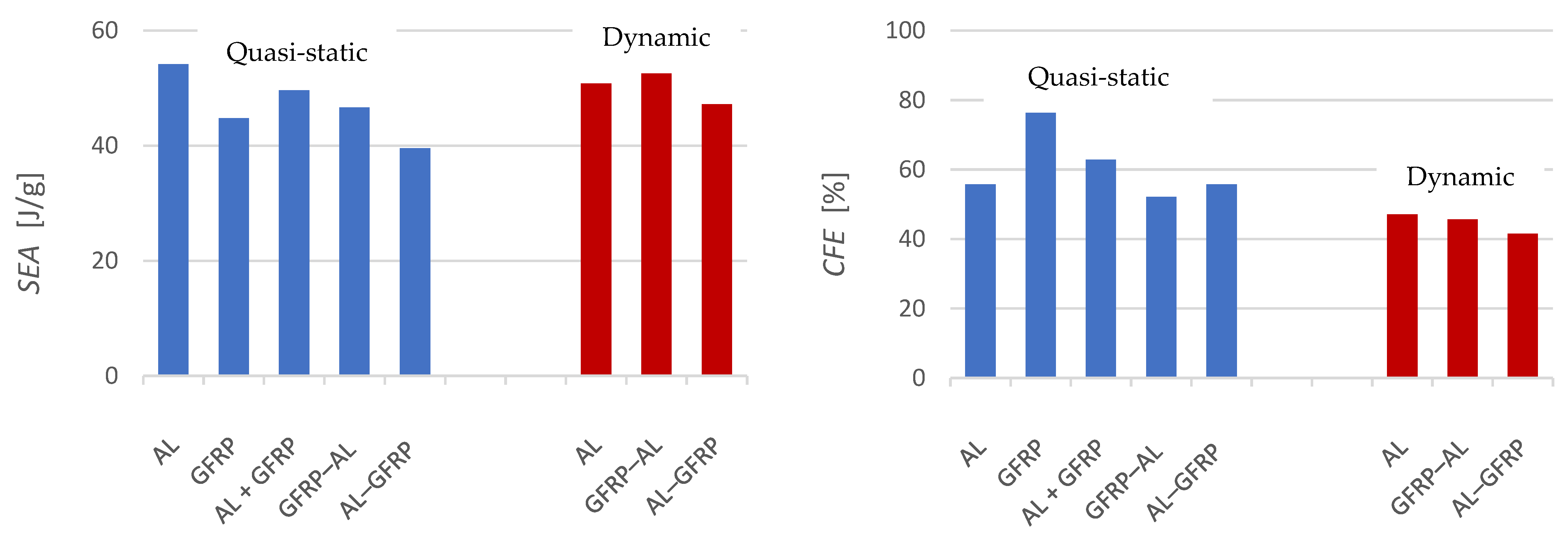
5.3.4. Specific Energy Absorption
5.3.5. Crush Force Efficiency
6. Conclusions
- The AL and GFRP specimens (i.e., the non-hybrid configurations) respectively collapsed in concertina and mushrooming modes—the most efficient collapse modes for metallic and composite tubular energy absorbers.
- The hybrid specimens were unable to match the combined crashworthiness performance of AL and GFRP specimens (i.e., as if they were a single energy absorber of two separate non-interacting tubes). This was attributed to the disadvantageous layer interaction that prevented each layer to collapse in its efficient mode.
- The tests on the hybrid configurations revealed that even small deviations in the fibre volume fraction can affect the specific energy absorption values and, to a much greater extent, the IPF values of the GFRP tubes.
- The energy absorption ability of the hybrid configurations improved in dynamic conditions. It was attributed to the beneficial strain rate sensitivity of the GFRP layer rather than of the aluminium layer (AA6063-F) which exhibited a small decrease in crashworthiness parameters.
- The GFRP specimens outperformed the other configurations in terms of crush force efficiency (CFE) reaching values over 65%.
- The CFE of the AL and hybrid specimens decreased in dynamic conditions. Considering the definition of CFE, this decrease indicates that the Fmax strain rate sensitivity was greater than that of MCF for the layouts tested.
Author Contributions
Funding
Acknowledgments
Conflicts of Interest
References
- Ambrosio, J.A.C. General Introduction to Structural Crashworthiness. In Crashworthiness. International Centre for Mechanical Sciences (Courses and Lectures); Springer: Vienna, Austria, 2001; Volume 423. [Google Scholar] [CrossRef]
- Yu, Z.; Amdahl, J. A review of structural responses and design of offshore tubular structures subjected to ship impacts. Ocean. Eng. 2018, 154, 177. [Google Scholar] [CrossRef] [Green Version]
- Crundwell, R.F. Sacrificial Anodes. In Shreir’s Corrosion; Cottis, B., Graham, M., Lindsay, R., Lyon, S., Richardson, T., Scantlebury, D., Stott, H., Eds.; Elsevier: Amsterdam, The Netherlands, 2010; p. 2763. [Google Scholar] [CrossRef]
- Lu, G.; Yu, T. Energy Absorption of Structures and Materials; Woodhead Publishing: Cambridge, UK; CRC Press: Boca Raton, FL, USA, 2003. [Google Scholar]
- Mamalis, A.G.; Manolakos, D.E.; Demosthenous, G.A.; Ioannidis, M.B. Crashworthiness of Composite Thin-Walled Structures; CRC Press: Boca Raton, FL, USA, 1998. [Google Scholar] [CrossRef]
- Wang, B.; Lu, G. Mushrooming of circular tubes under dynamic axial loading. Thin-Walled Struct. 2002, 40, 167. [Google Scholar] [CrossRef]
- Jones, N.; Abramowicz, W. Static and dynamic axial crushing of circular and square tubes. In Metal Forming and Impact Mechanics; Reid, S.R., Ed.; Pergamon Press: New York, NY, USA, 1985; p. 225. [Google Scholar] [CrossRef]
- Kim, J.; Jeong, M.; Böhm, H.; Richter, J.; Modler, N. Experimental investigation into static and dynamic axial crush of composite tubes of glass-fiber mat/PA6 laminates. Compos. Part B Eng. 2020, 181, 107590. [Google Scholar] [CrossRef]
- Lykakos, S.; Kostazos, P.K.; Manolakos, D.E. Quasi-static axial crushing of thin-walled steel tapered tubes with hybrid geometry: Experimental and numerical investigation. Int. J. Crash 2020. [Google Scholar] [CrossRef]
- Nia, A.A.; Hamedani, J.H.; Alavi Nia, A.; Haddad Hamedani, J. Comparative analysis of energy absorption and deformations of thin walled tubes with various section geometries. Thin-Walled Struct. 2010, 48, 946. [Google Scholar] [CrossRef]
- Tarlochan, F.; Samer, F.; Hamouda, A.M.S.; Ramesh, S.; Khalid, K. Design of thin wall structures for energy absorption applications: Enhancement of crashworthiness due to axial and oblique impact forces. Thin-Walled Struct. 2013, 71, 7. [Google Scholar] [CrossRef]
- Palanivelu, S.; van Paepegem, W.; Degrieck, J.; van Ackeren, J.; Dimitrios Kakogiannis, D.; Van Hemelrijck, D.; Wastiels, J.; Vantomme, J. Experimental study on the axial crushing behaviour of pultruded composite tubes. Polym. Test. 2010, 29, 224. [Google Scholar] [CrossRef] [Green Version]
- Pugsley, A.; Macaulay, M. The large scale crumpling of thin cylindrical columns. Q. J. Mech. Appl. Math. 1960, 13, 1–9. [Google Scholar] [CrossRef]
- Alexander, J.M. An approximate analysis of the collapse of thin cylindrical shells under axial loading. Q. J. Mech. Appl. Math. 1960, 13, 10. [Google Scholar] [CrossRef]
- Mamalis, A.G.; Johnson, W. The quasi-static crumpling of thin-walled circular cylinders and frusta under axial compression. Int. J. Mech. Sci. 1983, 25, 713. [Google Scholar] [CrossRef]
- Abramowicz, W.; Jones, N. Dynamic progressive buckling of circular and square tubes. Int. J. Impact. Eng. 1986, 4, 243. [Google Scholar] [CrossRef]
- Wierzbicki, T.; Bhat, S.U.; Abramowicz, W.; Brodkin, D. Alexander revisited─A two folding elements model of progressive crushing of tubes. Int. J. Solids Struct. 1992, 29, 3269. [Google Scholar] [CrossRef]
- Singace, A.A. Axial crushing analysis of tubes deforming in the multi-lobe mode. Int. J. Mech. Sci. 1999, 41, 865–890. [Google Scholar] [CrossRef]
- Hanssen, A.G.; Langseth, M.; Hopperstad, O.S. Static and dynamic crushing of circular aluminium extrusions with aluminium foam filler. Int. J. Impact. Eng. 2000, 24, 475. [Google Scholar] [CrossRef]
- Andrews, K.R.F.; England, G.L.; Ghani, E. Classification of the axial collapse of cylindrical tubes under quasi-static loading. Int. J. Mech. Sci. 1983, 25, 687. [Google Scholar] [CrossRef]
- Guillow, S.R.; Lu, G.; Grzebieta, R.H. Quasi-static axial compression of thin-walled circular aluminium tubes. Int. J. Mech. Sci. 2001, 43, 2103. [Google Scholar] [CrossRef]
- Hull, D. Axial crushing of fibre reinforced composite tubes. In Structural Crashworthiness; Jones, N., Wierzbicki, T., Eds.; Butterworths: Guildford, UK, 1983; p. 118. [Google Scholar]
- Mamalis, A.G.; Manolakos, D.E.; Demosthenous, G.A.; Ioannidis, M.B. Energy absorption capability of fibreglass composite square frusta subjected to static and dynamic axial collapse. Thin-Walled Struct. 1996, 25, 269. [Google Scholar] [CrossRef]
- Hull, D. A unified approach to progressive crushing of fibre- reinforced composite tubes. Compos. Sci. Technol. 1991, 40, 377. [Google Scholar] [CrossRef]
- Alhyari, O.; Newaz, G. Energy Absorption in Carbon Fiber Composites with Holes under Quasi-Static Loading. C 2021, 7, 16. [Google Scholar] [CrossRef]
- Mamalis, A.G.; Robinson, M.; Manolakos, D.E.; Demosthenous, G.A.; Ioannidis, M.B.; Carruthers, J. Crashworthy capability of composite material structures. Compos. Struct. 1997, 37, 109. [Google Scholar] [CrossRef]
- Khan, R.A.; Mahdi, E.; Cabibihan, J.J. Effect of fibre orientation on the quasi-static axial crushing behaviour of glass fibre reinforced polyvinyl chloride composite tubes. Materials 2021, 14, 2235. [Google Scholar] [CrossRef] [PubMed]
- Rogala, M.; Gajewski, J.; Ferdynus, M. The Effect of Geometrical Non-Linearity on the Crashworthiness of Thin-Walled Conical Energy-Absorbers. Materials 2020, 13, 4857. [Google Scholar] [CrossRef]
- Kaczyński, P. Crashworthiness Characteristic of Dynamically Expanded Circular Tubes Made of Light Alloys: Experimental and Theoretical Investigation. Materials 2020, 13, 5332. [Google Scholar] [CrossRef] [PubMed]
- Zhu, L.; Zhang, H.; Guo, J.; Wang, Y.; Lyu, L. Axial Compression Experiments and Finite Element Analysis of Basalt Fiber/Epoxy Resin Three-Dimensional Tubular Woven Composites. Materials 2020, 13, 2584. [Google Scholar] [CrossRef] [PubMed]
- Paz, J.; Costas, M.; Delgado, J.; Romera, L.; Díaz, J. Energy Absorption of Aluminium Extrusions Filled with Cellular Materials Under Axial Crushing: Study of the Interaction Effect. Appl. Sci. 2020, 10, 8510. [Google Scholar] [CrossRef]
- Zhu, G.; Sun, G.; Liu, Q.; Li, G.; Li, Q. On crushing characteristics of different configurations of metal-composites hybrid tubes. Compos. Struct. 2017, 175, 58. [Google Scholar] [CrossRef]
- Yao, S.; Chen, Z.; Xu, P.; Li, Z.; Zhao, Z. Experimental and numerical study on the energy absorption of polyurethane foam-filled metal/composite hybrid structures. Metals 2021, 11, 118. [Google Scholar] [CrossRef]
- Yang, H.; Lei, H.; Lu, G.; Zhang, Z.; Li, X.; Liu, Y. Energy absorption and failure pattern of hybrid composite tubes under quasi-static axial compression. Compos. Part B Eng. 2020, 198, 108217. [Google Scholar] [CrossRef]
- Sun, G.; Wang, Z.; Hong, J.; Song, K.; Li, Q. Experimental investigation of the quasi-static axial crushing behavior of filament-wound CFRP and aluminum/CFRP hybrid tubes. Compos. Struct. 2018, 194, 208. [Google Scholar] [CrossRef]
- Meyers, M.A. Dynamic Behaviour of Materials; John Wiley & Sons: New York, NY, USA, 1994. [Google Scholar] [CrossRef]
- Aktay, L.; Toksoy, A.K.; Güden, M. Quasi-static axial crushing of extruded polystyrene foam-filled thin-walled aluminum tubes: Experimental and numerical analysis. Mater. Des. 2006, 27, 556. [Google Scholar] [CrossRef] [Green Version]
- Abdewi, E.F.; Sulaiman, S.; Hamouda, A.M.S.; Mahdi, E. Quasi-static axial and lateral crushing of radial corrugated composite tubes. Thin-Walled Struct. 2008, 46, 320. [Google Scholar] [CrossRef]
- Luo, H.; Yan, Y.; Meng, X.; Jin, C. Progressive failure analysis and energy-absorbing experiment of composite tubes under axial dynamic impact. Compos. Part B Eng. 2016, 87, 1–11. [Google Scholar] [CrossRef]
- Wang, Z.; Jin, X.; Li, Q.; Sun, G. On crashworthiness design of hybrid metal-composite structures. Int. J. Mech. Sci. 2020, 171, 105380. [Google Scholar] [CrossRef]
- Kostazos, P.K.; Lykakos, S.S.A.; Kyritsis, P.-A.E.; Manolakos, D.E. Quasi-static axial crushing of multi-walled (spiral) aluminium tubes fabricated by roll bending: Experimental and numerical investigation. Thin-Walled Struct. 2021, 159, 107237. [Google Scholar] [CrossRef]
- Olabi, A.G.; Morris, E.; Hashmi, M.S.J. Metallic tube type energy absorbers: A synopsis. Thin-Walled Struct. 2007, 45, 706. [Google Scholar] [CrossRef] [Green Version]
- Hsu, S.S.; Jones, N. Dynamic axial crushing of aluminium alloy 6063-T6 circular tubes. Lat. Am. J. Solids Struct. 2004, 1, 277. [Google Scholar]
- Thornton, P.H. The crush behaviour of pultruded tubes at high strain rates. J. Compos. Mater. 1990, 24, 594. [Google Scholar] [CrossRef]


| Material | AA6063-F | E-Glass Fibre | Epoxy Resin 1 | Units |
|---|---|---|---|---|
| Proof stress (0.2%) | 50 | – | – | MPa |
| Tensile strength (compressive strength) | 120 | 2700 | 35 (72) | MPa |
| Young’s modulus | 69.5 | 72 | 1.6 | GPa |
| Poisson’s ratio | 0.33 | 0.22 | 0.34 | – |
| Density | 2700 | 2600 | 1100 | kg/m3 |
| Viscosity at 20 °C | – | – | 420 | MPa.s |
| Specimen | Mass [g] | GFRP Fibre Vol. Fraction † | Diameter [mm] | Loading Condition | Overall Strain Rate (s−1) | δT * [mm] | IPF * [kN] | Fmax * [kN] | EA† [kJ] | MCF† [kN] | SEA† [J/g] | CFE† [%] | ||||||
|---|---|---|---|---|---|---|---|---|---|---|---|---|---|---|---|---|---|---|
| AL * | E-glass * | Epoxy † | Total * | Internal * | Interface † | External * | ||||||||||||
| AL | 401 | 45.2 | - | - | 45.2 | - | 35.6 | - | 38.6 | Dynamic | 29.1 | 65.5 | 25.5 | 49.5 | 1.52 | 23.1 | 51.2 | 46.7 |
| 402 | 45.2 | - | - | 45.2 | - | 35.6 | - | 38.6 | Dynamic | 28.3 | 70.5 | 25.9 | 48.0 | 1.61 | 22.8 | 50.4 | 47.5 | |
| 403 | 45.2 | - | - | 45.2 | - | 35.6 | - | 38.6 | Quasi-static | 1.67 × 10⁻³ | 60.0 | 43.8 | 43.8 | 1.49 | 24.9 | 55.0 | 56.8 | |
| 404 | 45.2 | - | - | 45.2 | - | 35.6 | - | 38.6 | Quasi-static | 1.67 × 10⁻³ | 60.0 | 44.1 | 44.1 | 1.44 | 24.1 | 53.3 | 54.6 | |
| GFRP–AL | 405 | 45.2 | 25.4 | 16.1 | 86.7 | 0.40 | 35.6 | 38.6 | 43.0 | Dynamic | 27.0 | 32.5 | 43.3 | 93.4 | 1.63 | 50.1 | 57.8 | 53.7 |
| 406 | 45.2 | 25.4 | 17.3 | 87.9 | 0.38 | 35.6 | 38.6 | 43.7 | Dynamic | 23.3 | 36.5 | 55.0 | 110.7 | 1.52 | 41.6 | 47.3 | 37.5 | |
| 407 | 45.2 | 25.4 | 16.5 | 87.1 | 0.39 | 35.6 | 38.6 | 42.9 | Quasi-static | 1.67 × 10⁻³ | 60.0 | 78.3 | 78.3 | 2.26 | 37.6 | 43.2 | 48.0 | |
| 408 | 45.2 | 25.4 | 17.1 | 87.5 | 0.39 | 35.6 | 38.6 | 42.9 | Quasi static | 1.67 × 10⁻³ | 60.0 | 79.1 | 79.1 | 2.67 | 44.6 | 50.1 | 56.3 | |
| GFRP | 410 | - | 25.4 | 15.8 | 41.2 | 0.40 | 38.6 | - | 43.0 | Quasi-static | 1.67 × 10⁻³ | 60.0 | 22.0 | 22.0 | 1.10 | 18.3 | 44.5 | 83.2 |
| 412 | - | 25.4 | 16.2 | 41.6 | 0.40 | 38.6 | - | 42.9 | Quasi-static | 1.67 × 10⁻³ | 60.0 | 27.0 | 27.0 | 1.13 | 18.8 | 45.1 | 69.5 | |
| AL–GFRP | 413 | 45.2 | 21.1 | 17.1 | 91.7 | 0.34 | 29.6 | 35.6 | 38.6 | Dynamic | 25.4 | 35.5 | 39.2 | 104.3 | 1.54 | 43.3 | 47.2 | 41.5 |
| 414 | 45.2 | 25.4 | 22.0 | 92.6 | 0.33 | 29.4 | 35.6 | 38.6 | Quasi-static | 1.67 × 10⁻³ | 60.0 | 63.9 | 63.9 | 2.03 | 33.9 | 36.6 | 53.1 | |
| 415 | 45.2 | 25.4 | 21.2 | 91.8 | 0.34 | 29.6 | 35.6 | 38.6 | Quasi-static | 1.67 × 10⁻³ | 60.0 | 66.8 | 66.8 | 2.34 | 39.0 | 42.5 | 58.4 | |
Publisher’s Note: MDPI stays neutral with regard to jurisdictional claims in published maps and institutional affiliations. |
© 2021 by the authors. Licensee MDPI, Basel, Switzerland. This article is an open access article distributed under the terms and conditions of the Creative Commons Attribution (CC BY) license (https://creativecommons.org/licenses/by/4.0/).
Share and Cite
Lykakos, S.S.A.; Kostazos, P.K.; Venetsanos, O.-V.; Manolakos, D.E. Crashworthiness Performance of Aluminium, GFRP and Hybrid Aluminium/GFRP Circular Tubes under Quasi-Static and Dynamic Axial Loading Conditions: A Comparative Experimental Study. Dynamics 2021, 1, 22-48. https://0-doi-org.brum.beds.ac.uk/10.3390/dynamics1010004
Lykakos SSA, Kostazos PK, Venetsanos O-V, Manolakos DE. Crashworthiness Performance of Aluminium, GFRP and Hybrid Aluminium/GFRP Circular Tubes under Quasi-Static and Dynamic Axial Loading Conditions: A Comparative Experimental Study. Dynamics. 2021; 1(1):22-48. https://0-doi-org.brum.beds.ac.uk/10.3390/dynamics1010004
Chicago/Turabian StyleLykakos, Stavros S. A., Protesilaos K. Kostazos, Odysseas-Vasilios Venetsanos, and Dimitrios E. Manolakos. 2021. "Crashworthiness Performance of Aluminium, GFRP and Hybrid Aluminium/GFRP Circular Tubes under Quasi-Static and Dynamic Axial Loading Conditions: A Comparative Experimental Study" Dynamics 1, no. 1: 22-48. https://0-doi-org.brum.beds.ac.uk/10.3390/dynamics1010004