1. Introduction
The International Maritime Organization’s [
1] Marine Environment Protection Committee published its final third IMO greenhouse gas (GHG) study report in 2014 providing updated estimates for GHG emissions from ships. In that report, for the year 2012, total shipping emissions were approximately 949 million tonnes CO
2 and 972 million tonnes CO
2e for GHGs combining CO
2, CH
4 and N
2O. International shipping emissions for 2012 were estimated to be 796 million tonnes CO
2 and 816 million tonnes CO
2e. International shipping thus accounted for approximately 2.2% and 2.1% of global CO
2 and GHG emissions on a CO
2 equivalent (CO
2e) basis, respectively. In addition, refrigerant and air conditioning gas released from shipping contributed an additional 15 million tons in CO
2 equivalent emissions. In the study, military forces were excluded from the total and international shipping calculations.
To reduce the emission of greenhouse gases, specifically CO2 emissions, emitted by ships, the Energy Efficiency Design Index (EEDI) for new ships and the Ship Energy Efficiency Management Plan (SEEMP) for all ships entered into force on 1 January 2013. New ships are ships that enter the fleet from 2013. Implementing CO2 reduction measures will result in a significant reduction in fuel consumption, leading to a significant saving in fuel costs to the shipping industry.
The main and auxiliary engines are used to propel the ship, and to drive generators to produce electricity, respectively. Despite the great technological development of engines, the maximum efficiency is still less than 50%. The main and auxiliary engines onboard ships produce significant quantities of heat. The primary source of waste heat of main and auxiliary engines is the exhaust gas heat dissipation, which accounts for about half of the total waste heat, i.e., about 25% of the total fuel energy.
For naval ships, the environment (decreased emissions), stealth demands (hydrodynamic, acoustic, magnetic, infrared, radar signatures) and efficiency (decreased fuel costs) are of importance. The required precautions to achieve the specified level of stealth features should be taken during both the design and operating phase. CO2 reduction measures as well as reduction and management of ship signatures must also be implemented by naval ships. To continue the Navy’s leadership role in protecting the marine environment, the search for new energy conservation methods that can be applied on board naval ships is necessary. Thermally driven heat pumps for heating and cooling can be promising solutions. Today, heating, cooling and refrigeration systems onboard ships are based on mechanical vapour compression. These cycles are powered by electrical energy generated by the combustion of fossil fuels, and the process contributes to an increase in greenhouse gases and the generation of air pollutants.
One way to find a new solution to this problem is to apply an absorption refrigeration (AR)/heat pump (AHP) system to provide the required heating and cooling loads for the HVAC system instead of the traditional vapour-compression heat pump. The main problem with absorption systems is that they are more bulky than conventional vapour-compression systems. This is because an AR/AHP has more components and as the heat and mass transfer of absorption equipment is poor, large surface areas are required. Ezgi [
2] presented design and thermodynamic analysis of a water-lithium bromide AHP as an HVAC system for a naval surface ship application and compared with those of a vapour-compression heat pump. Ezgi [
2] performed calculations for diesel engine loads of 50%, 75%, 85%, 100%. The temperatures of evaporator, condenser, absorber are 4 °C, 50 °C, 35 °C, respectively, and generator temperatures were 90 °C, 95 °C, 100 °C, 105 °C and 110 °C. At the end of 1000 operating hours a year of a naval surface ship, it was stated that the AHP system could save 22,952–81,961 L of diesel fuel in the heating cycle and 21,135–75,477 L of diesel fuel in the cooling cycle and would reduce its annual CO
2 emissions by 60.41–215.74 tons in the heating cycle and 55.63–198.67 tons in the cooling cycle, depending on the engine load and COP of the vapour-compression heat pump.
Another type of system is known as an ejector refrigeration/heat pump. Riffat
et al. [
3] and Ma
et al. [
4] stated that ejector refrigeration is one of the most promising technologies because of its relative simplicity and low capital cost when compared to an absorption refrigerator. This is a heat-operated cycle capable of utilising solar energy, waste energy, natural gas or hybrid sources (e.g., solar/gas). The ejector heat refrigeration/heat pump has no moving parts and so is simple and reliable. In addition, it has the potential of long life and, unlike vapour compression systems, produces no noise or vibration.
Chen
et al. [
5] provided a literature review on the recent developments in ejectors, applications of ejector refrigeration systems. Ejector refrigeration systems (ERS) are more attractive compared with traditional vapour compression refrigeration systems, with the advantage of simplicity in construction, installation and maintenance. Moreover, in an ERS, compression can be achieved without consuming mechanical energy directly. Furthermore, the utilization of low-grade thermal energy (such as solar energy and industrial waste heat) in the system can help mitigate the problems related to the environment, particularly by reduction of CO
2 emissions from the combustion of fossil fuels.
An ejector is a simple device in which high pressure stream (the primary fluid) is used to compress low pressure stream (the secondary fluid) to a higher pressure (discharge pressure). A number of experimental studies involving ejectors have been reported in the literature. Hsu [
6] investigated by analytical methods the efficiency of an ejector heat pump with the refrigerants 11, 113, and 114. Huang
et al. [
7] carried out a 1-D analysis for the prediction of the ejector performance at critical mode operation. El-Dessouky
et al. [
8] developed semi-empirical models for the design and rating of steam jet ejectors. Alexis [
9] modelled the steam-ejector refrigeration system and estimated the maximum flow entrainment ratio for constant generator pressure (6–8 bar), condenser (40–50 °C) and evaporator temperature (4–10 °C). Sanaye and Niroomand [
10] presented the modelling and optimization of a ground-coupled steam ejector heat pump with a closed vertical ground heat exchanger.
Steam-ejector refrigeration systems are used in food processing plants, gas plants, breweries, the rubber and vulcanizing, paper and pulp, paints and dyes, pharmaceutical and chemical industries, and edible oil refineries. In the literature, although the ejector refrigeration cycle is most commonly used for refrigeration in land-based plants, there has been no report that an ejector heat pump system has been installed on board ships.
The most important difference between land and marine refrigeration is the need for a cooling tower in land-based applications and seawater in marine applications to eject heat from the condenser to ambient air. Cooling towers increase the initial system costs, and require regular maintenance and require extra space for their installation. The development of seawater-cooled steam-ejector refrigeration technology can effectively eliminate these disadvantages.
Also, no investigation has been conducted yet on a seawater-cooled steam ejector refrigeration/heat pump system for a naval ship application. One possible reason why steam ejector refrigeration systems have never been applied in ships before is the lower COP—0.2~0.3—compared to vapour compression systems and other thermally driven technologies. The COP also drops significantly at operation away from the design point. Another is the lack of performance data from commercial applications to provide confidence in the ship applications of the technology and the need for uninterrupted cooling and heating on ships, especially in naval ships.
Therefore, this study focuses on the dual use of steam ejector technology to produce heating and cooling onboard a naval ship. A theoretical study of the possibilities for application of steam ejector refrigeration/heat pump systems for cooling and heating of naval surface ships is presented. Waste heat from the main diesel engine exhaust gas is utilized. The technical characteristics of the system are analyzed and its economical and environmental benefits are discussed.
2. System Selection for Naval Surface Ships
In general, the details of merchant ship air conditioning also apply to warships. However, all ships are governed by their specific ship specifications, and naval ships are usually governed by military specifications, which require an excellent air-conditioning system and equipment performance in the extreme environment of naval ship duty.
Design conditions for naval surface ships have been established as a compromise. These conditions consider the large cooling plants required for internal heat loads generated by machinery, weapons, electronics and personnel.
Today, heat pumps for heating and cooling on board naval ships are mechanically driven. Seawater is used for condenser cooling. The equipment described for merchant ships also applies to naval surface ships. Fans, cooling coils, heating coils with steam or electric duct heaters and air handling units (AHU) which are used to regulate and circulate air as part of an HVAC system are used on board naval ships.
Steam ejector refrigeration (SER) and steam ejector heat pump (SEHP) systems are a good choice for naval surface ships because of their lower energy consumption, CO2 emissions, EEDI, infrared and acoustic signature, simple, compact construction and corrosion resistance and because they can be used with water, which is the most environment friendly refrigerant. The SER/SEHP system can be fitted into the machinery space of a ship. The system serves by supplying chilled water in cooling mode and hot water in heating mode to fan coil units located in various parts of the naval ship.
3. The Case Naval Ship
The case naval surface ship has two main internal combustion engines that propel the ship. The specification of the each diesel engine on the naval ship is given in
Table 1 [
11]. The propeller demand data are presented in
Table 2 [
11].
Table 1.
Specification of a diesel engine on a naval ship.
Table 1.
Specification of a diesel engine on a naval ship.
| Engine Maximum Continuous Output | 3000 kW |
|---|
| Engine speed | 750 rpm |
| Cylinder bore | 320 mm |
| Stroke | 400 mm |
| Cylinder configuration | 6, in-line |
| Backpressure, max. | 4.0 kPa |
Table 2.
Propeller demand data.
Table 2.
Propeller demand data.
| Engine % Load | Fuel Consumption, g·(kW·h)−1 | Exhaust Gas Temperature after Turbocharger, °C | Exhaust Gas Flow kg·s−1 |
|---|
| 50 | 191 | 315 | 3.71 |
| 75 | 182 | 345 | 4.43 |
| 85 | 181 | 336 | 4.96 |
| 100 | 185 | 380 | 5.40 |
The total heating and cooling loads of the case naval surface ship are 144 kW and 116 kW, respectively. The case naval surface ship has two marine diesel generator sets for auxiliary power production, each with a generator power of 240 kVA. Heating load (144 kW) is met by electric duct heaters. Cooling load (116 kW) is met by a seawater cooled chiller unit.
4. System Design
This study focuses on the dual use of ejector technology to produce heating and cooling on board a naval ship. The design criteria are given in
Table 3, which is determined according to Loydu’s Rules for the Classification of Naval Ships and based on the naval distillate fuel (NATO symbol F-76) used on power systems by the navies of NATO countries.
Table 3.
The design criteria.
Table 3.
The design criteria.
| Type of Heat Pump | Steam Ejector |
|---|
| Energy source | Diesel engine exhaust gas |
| Diesel engine fuel type | NATO F-76 Diesel |
| Heating Mode |
| Hot water temperature flows through the condenser | 45 °C–40 °C |
| Evaporator | Seawater (−2 °C–+32 °C) |
| Cooling Mode |
| Chilled water temperature flows through the evaporator | 7 °C–12 °C |
| Condenser | Seawater (−2 °C–+32 °C) |
The working fluid is water in SER/SEHP system. Water is a natural working fluid. It is an excellent working fluid for high-temperature industrial heat pumps because of its favourable thermodynamic properties and the fact that it is neither flammable nor toxic. Water is inexpensive and has no environment impact (zero ozone depletion and global warming potential). Water has an extremely high heat of vaporization that causes a low circulation rate for given heating and cooling capacity. At low temperatures the saturation pressures are low (0.008129 bar at 4 °C) and the specific volumes are high (157.3 m3·kg−1 at 4 °C) at typical evaporator conditions. Therefore, low mechanical power is required for the pump.
The system is not considered under the diesel engine load of 50% as long term operation at lower loads, typically below 50% of its maximum rated load, reduces engine service life. If the engine of the naval ship is in standby or under very low engine loads (below 50%), the heating and cooling load for the naval surface ship will be met from a vapour compression heat pump. In addition, vapour compression heat pumps onboard naval ship are operated as reserves in emergency situations, at naval base or during periodic engine overhauls in naval shipyards.
The expansion tanks are designed to compensate for the changing volume of the water in the SER/SEHP system to maintain the static pressure created by the pump at the utilisation level in water production and to compensate for any changes in the water flow rate.
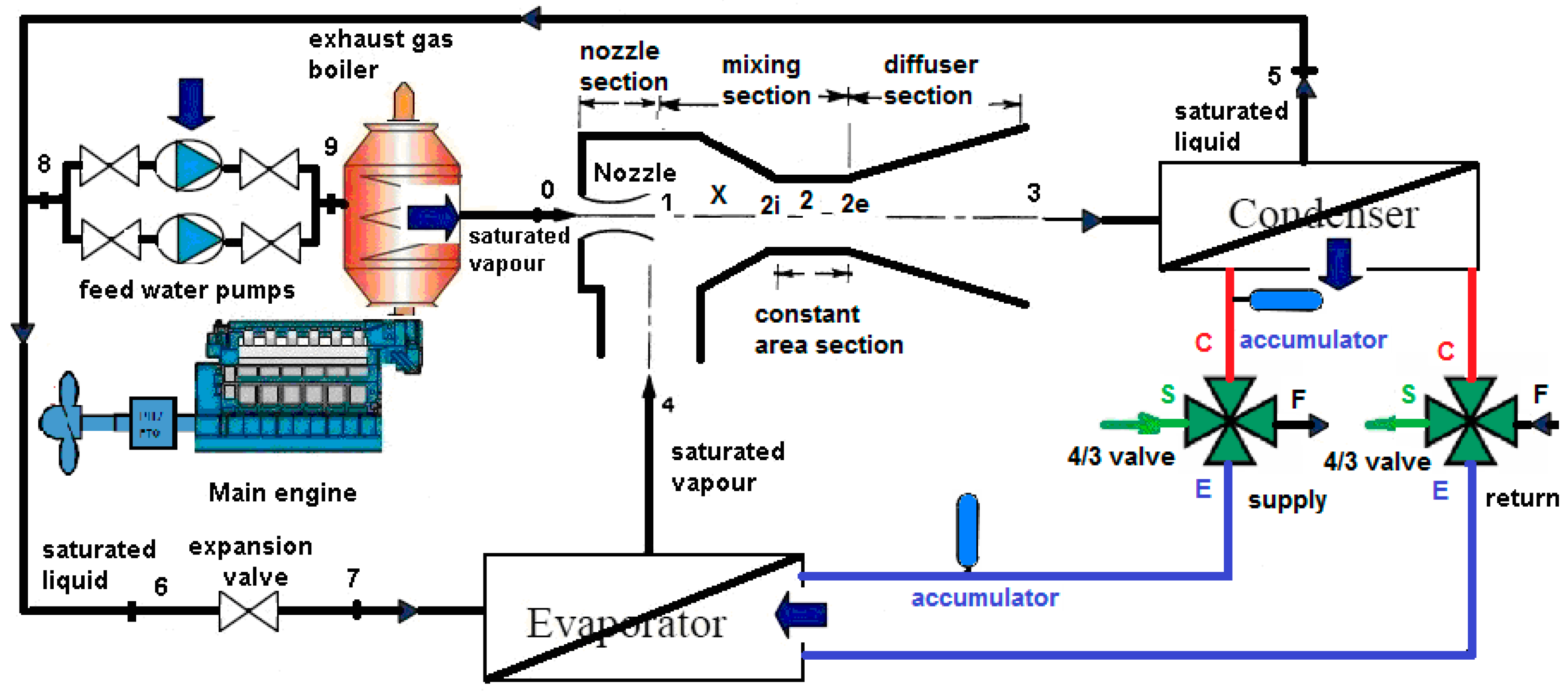
A SER/SEHP system design for naval ship application is presented in
Figure 1. The SER/SEHP is driven by the thermal energy of a diesel engine and consists of an ejector, a boiler, an evaporator, a condenser, an expansion valve and a circulation pump. In the shown system, high-pressure steam expands while flowing through the nozzle. The expansion causes a drop in pressure and an enormous increase in velocity. Due to the high velocity, vapour from the evaporator is drawn into the swiftly moving steam and the mixture enters the diffuser. The velocity is gradually reduced in the diffuser but the pressure of the steam at the condenser is increased 5–10 times more than that at the entrance of the diffuser. This pressure value corresponds to a condensation temperature of 50 °C. The latent heat of condensation is transferred to the condenser water. The condensate is pumped back to the boiler. The cooled water is pumped as the refrigeration carrier to the fan-coil unit. The heated water is pumped as the heating carrier to the fan coil unit.
Figure 1.
SER/SEHP system design for a naval ship.
Figure 1.
SER/SEHP system design for a naval ship.
The evaporator temperature has to be designed at 4 °C to cool water of 12 °C for the air conditioning of the space to be maintained between 24 °C and 27 °C.
The condenser temperature depends on the seawater temperature. According to Loydu’s [
12] Rules for the Classification of Naval Ships, the selection, layout and arrangement of all shipboard machinery, equipment and appliances should ensure faultless continuous operation under the seawater temperature of −2 °C to +32 °C and the air temperature outside the ship of −25 °C to +45 °C.
The exhaust gas boiler is used to recover exhaust waste heat from the diesel engine. Each engine has a separate exhaust gas boiler. The pressure drop of the gas side of the exhaust gas boiler is set to 3 kPa maximum and the back pressure of the exhaust gas system is 4 kPa maximum. Fresh water conservation onboard a naval ship is very important. Seawater is the main coolant on board naval ships, like in other ships. Seawater is a free and renewable source for cooling onboard ships. Therefore, the condenser and evaporator used in this system are seawater-cooled heat exchangers. However, seawater-cooled heat exchangers are prone to fouling, which causes the thermohydraulic performance of heat transfer equipment to decrease with time [
13]. Design fouling resistances must also be taken into account when dimensioning the exhaust gas boiler and heat exchangers because the boiler and heat exchangers are subject to fouling and must operate for long periods without being cleaned. Thus, the design fouling resistances of the engine exhaust gas and seawater are set to
Rf,exh = 1.761 m
2·K·(kW)
−1,
Rf,s = 0.088 m
2·K·(kW)
−1, respectively [
14].
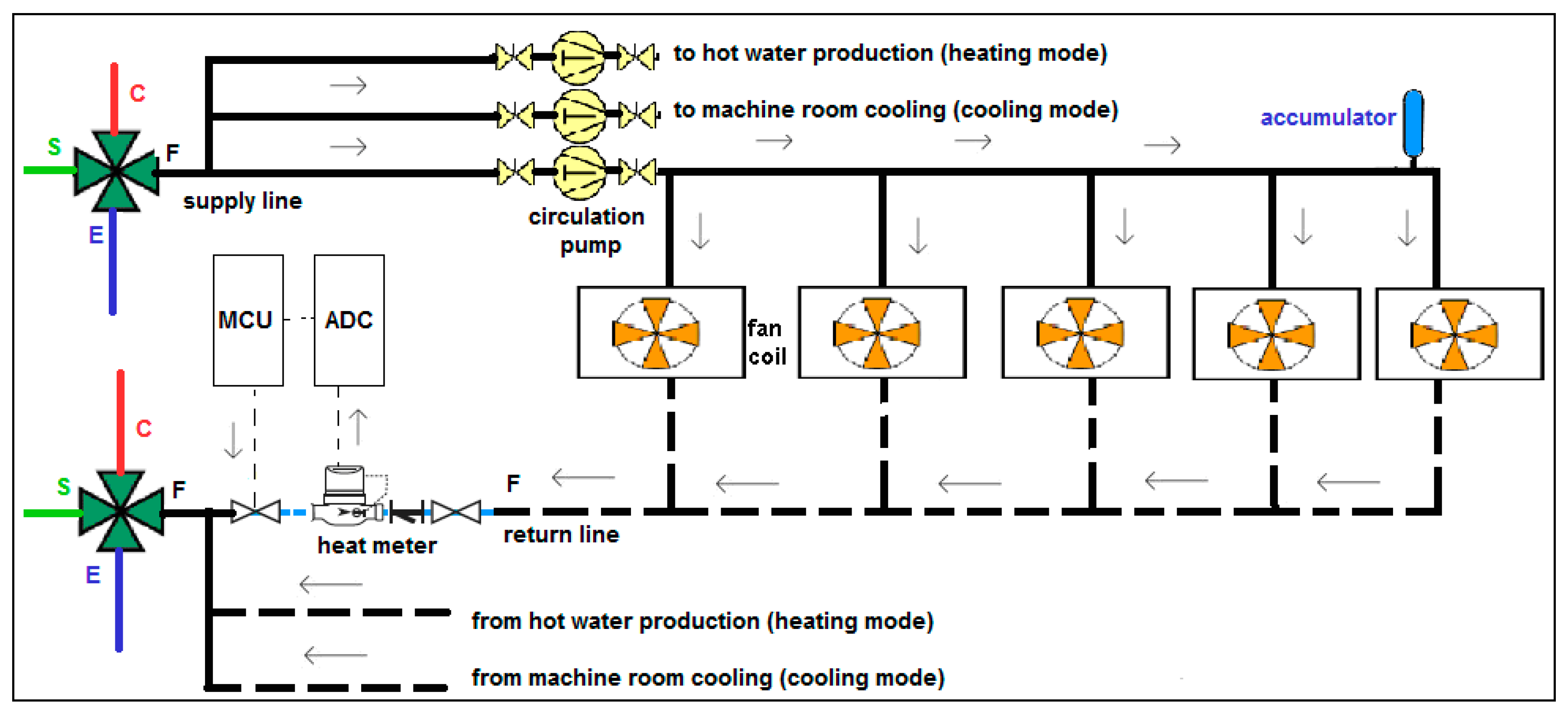
Seawater flows through the evaporator during the heating mode, through the condenser during the cooling mode all the time. To achieve this flow, two 4-way, 3-position (4/3) rotary valves (also called CEFS valves) are used for heating and cooling in the system. One of the 4/3 valves is the supply and the other is the return valve. The three positions of the rotary valve are the heating mode, closed and cooling mode. A fan coil system is integrated with CEFS valves in a SEHP system as shown in
Figure 2. Heat produced with the SER or SEHP system is transferred to the fan-coil units. The heat is mainly consumed in fan coil units. A heat meter is used to measure the heat returning from fan coil units. The residual heat is sent to hot water production in heating mode or to machine room cooling in cooling mode. An analog-to-digital converter (ADC) is used that converts a continuous physical quantity (usually voltage) to a digital number that represents the quantity's amplitude. A servo valve is used to control flow through the heat meter.
Figure 2.
Integration of fan coil and CEFS valves design for a naval ship.
Figure 2.
Integration of fan coil and CEFS valves design for a naval ship.
5. Thermodynamic Analysis
The thermodynamic design of the ejector heat pump system by the first law only is usually based on given or assumed steady-state operating conditions. The condenser and evaporator temperatures are fixed. The system boiler heat transfer rates are also known.
The fundamental simplifications assumed for the model are as follows:
Steady state of the SER/SEHP
No radiation heat transfer
The primary and secondary fluids are saturated and have the same molecular weight and ratio of specific heats.
Water at the condenser outlet is saturated liquid
Water at the evaporator outlet is saturated vapour
Pressure losses in the pipes and all heat exchangers are negligible
The primary fluid expands through the nozzle from the boiler pressure to the evaporator pressure.
The pressure drop and momentum of the secondary flow are negligible.
There is no wall friction.
All fluid properties are uniform over the cross section after complete mixing at
Section 2.
Potential energy is negligibly small in the energy equations.
The exit velocity at the ejector outlet is ignored.
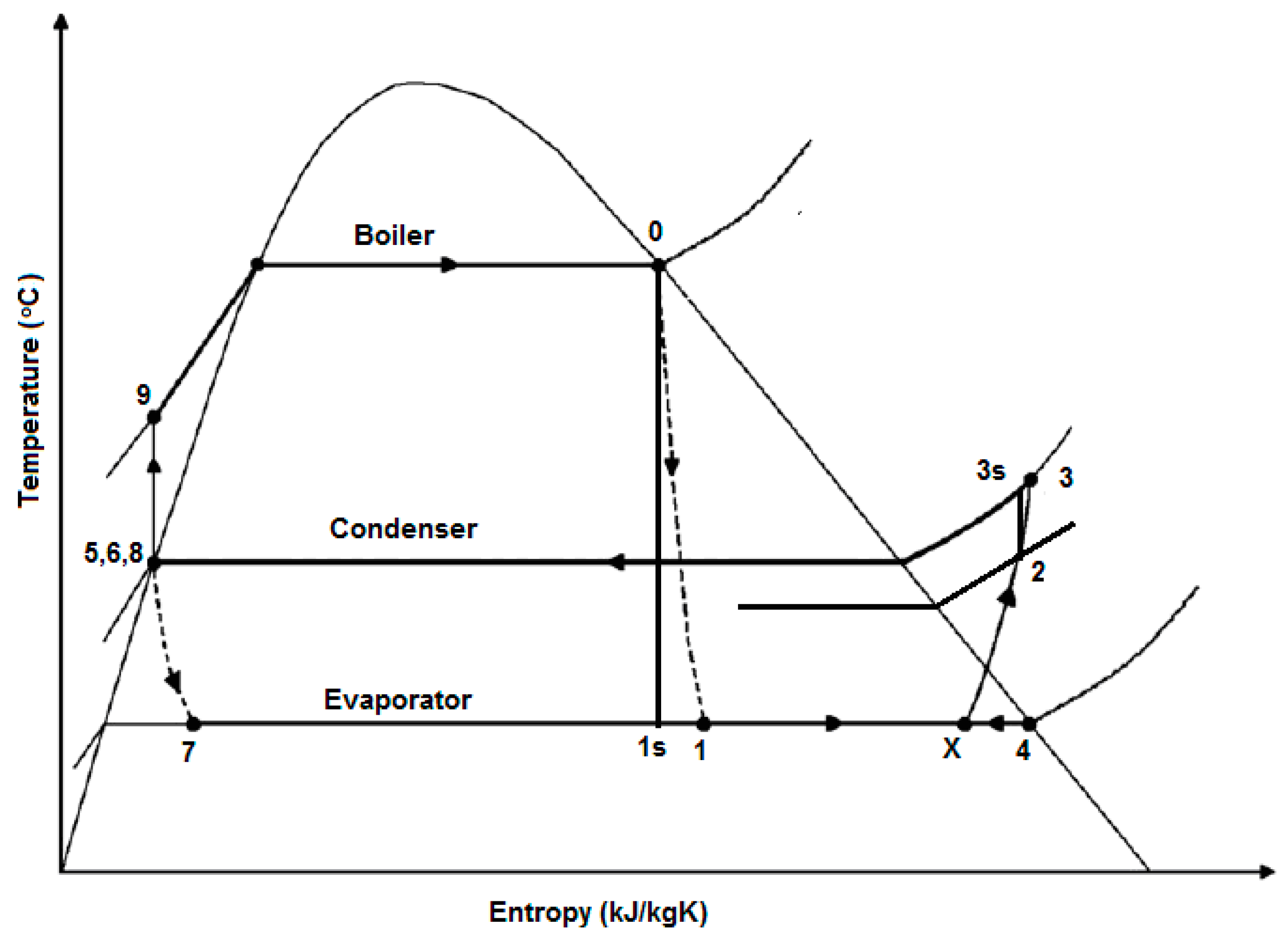
The T-s diagram of the steam ejector heat pump cycle is shown in
Figure 3. Saturated motive steam enters the ejector at a high pressure P
0, temperature T
0 and zero velocity corresponding to state (0) and expands to a pressure at state (1). The saturated secondary vapour enters the ejector at pressure P4 and zero velocity corresponding to state (4).
Figure 3.
T-s diagram of the steam ejector refrigeration and heat pump cycle.
Figure 3.
T-s diagram of the steam ejector refrigeration and heat pump cycle.
5.1. Nominal Heat Balance
The conservation of mass principle is expressed as:
To obtain a control volume at steady state, the equation is reduced to:
The energy rate balance is expressed as:
To obtain a control volume at steady state and to disregard the changes in the kinetic and potential energies of the flowing streams from inlet to exit, the equation is reduced to:
5.2. Main Engine
The heat transfer rate from the engine exhaust gas to the exhaust gas boiler is expressed as:
where
is the engine exhaust gas mass flow rate,
is the engine exhaust gas specific enthalpy at the entrance of the exhaust gas boiler and
is the engine exhaust gas specific enthalpy at the exit of the exhaust gas boiler.
5.3. Exhaust Gas Properties
The exhaust gas properties, which include specific heat at constant pressure, dynamic viscosity and thermal conductivity, should be determined for the heat transfer analysis. The main components of the exhaust gas of a diesel engine are CO2, H2O, N2 and O2. The mass fractions of these components vary with the operating conditions of the engine. When the engine operates at steady state, the injected fuel quantity and the intake air amount can be measured on the engine test bench.
Except for very low engine loads, the exhaust temperature of a marine engine is between 300 °C and 380 °C, and the exhaust pressure is slightly higher than the atmospheric pressure. Therefore, exhaust gas can be treated as a mixture of ideal gases. The specific enthalpy, specific heat and density of exhaust gas can be calculated as follows [
15]:
5.4. Exhaust Gas Boiler
The heat transfer rate of the exhaust gas boiler is expressed as:
The mass flow rate of the steam is:
5.5. Steam Ejector
The thermodynamic properties at initial states for steam are calculated from the saturation property. At 50 °C, the saturation pressure of water is 12.350 kPa. At pressures below this value, water vapour can be treated as an ideal gas with negligible error (under 0.2 percent), even when it is a saturated vapour [
16].
The performance of an ejector is measured by its entrainment ratio w which is the mass flow rate ratio of the secondary flow to that of the primary flow. It is given as [
6]:
The efficiency of an ejector can be defined by [
6]:
The ejector structure is normally characterised by the area ratio
which is defined as the cross-section area of the constant area section divided by that of the primary nozzle throat. It is given as [
17]:
For inlet and outlet conditions, the conservation of energy is given as:
5.5.1. Nozzle Section
Nozzle efficiency is given as [
16]:
Assuming zero entrance velocity, the velocity of the primary fluid at the nozzle exit is:
The Mach number, M, is the ratio of the actual velocity of the fluid to the velocity of sound at the same state. The properties of a fluid at a location where the Mach number is unity (the throat) are called critical properties, and the above ratios are called critical ratios. When steam enters the nozzle as a saturated vapour, the critical-pressure ratio becomes [
16]:
Since the ratio of the exit-to-inlet pressure (P4/P0) is less than the critical pressure ratio, the flow is choked at the nozzle. Then the velocity at the throat, Vt, is the sonic velocity, and the throat pressure, Pt, is the critical pressure.
5.5.2. Mixing Section
Conservation of energy is:
Conservation of momentum is [
6]:
Including mixing efficiency for the mixing chamber, the momentum equation reduces to:
5.5.3. Constant Area Section
A normal shock wave occurs if the velocity of the mixing fluid entering the constant area section is supersonic. In this case, a sudden reaction in the mixture velocity and a rise in the pressure take place [
18]. Also, that the primary and secondary streams mix in the mixing chamber and enter a normally choked (sonic flow conditions at the throat) secondary converging-diverging nozzle was stated by [
19]:
Conservation of energy is:
Conservation of momentum is:
The Mach number of the mixed flow at
Section 2 after the shock wave is
From Equations (19), (22) and (28), the cross-sectional area, A
2, is solved by:
ASHRAE [
20] proposes that the constant area throat section be typically 3–5 throat diameters long to accommodate the shock pattern and its axial movement under load.
5.5.4. Diffuser
Conservation of energy is:
The performance of a diffuser is usually expressed in terms of the diffuser and is given as Çengel and Boles [
16]:
5.5.5. The Optimum Mixing Constant Area
The optimum mixing constant section area, A2, can be found by maximizing
. Hsu [
6] calculated six simultaneous equations containing six unknown differentials, ds
2, dV
2, dh
2, dv
2, dA
2 and dP
2. The optimum criterion to operate an ejector for given conditions is given as:
Finally, M
2 and P
2 values for the optimum mixing constant section area are calculated as:
5.6. Condenser
The rate of heat transfer from the condenser is:
5.7. Expansion Valve
The throttling model yields the result that:
5.8. Evaporator
The rate of heat transfer to the evaporator is:
5.9. Feed Water Pump
The power input to the pump is:
The following is an alternative to Equation (38) for evaluating the pump work:
The work input to the system in the pump is small and neglected in the calculation of the coefficient of performance (COP) and efficiency. However; in practice, it is usually estimated to size the driving motor:
5.10. Overall Mass and Energy Balance of the System
The energy rate balance at steady state is:
5.11. COP
The performance of refrigerators and heat pumps is expressed in terms of the COP, which is defined for a vapour-compression refrigeration/heat pump as:
5.12. Solution Procedure
Define the design parameters, which include the heat input for the boiler (), pressures of the primary motive steam (P0), secondary suction vapour (P4), condenser (P3)
Define the efficiencies of the nozzle, mixing and diffuser ()
Calculate the mass flow rate of steam ()
Calculate the primary flow velocity (V1)
Calculate the Mach number (M
2) and pressure (P
2) at
Section 2 for optimum mixing constant area (A
2)
Calculate the optimum mixing constant cross-sectional area (A2)
Assume value of the entropy (s2) with pressure (P2)
Calculate the enthalpy (h2) and specific volume (v2)
Calculate the enthalpy () at state 3s from entropy (s2) and pressure (P3)
Calculate the enthalpy (h3)
Calculate the velocity (V2)
Calculate the secondary mass flow rate ()
Check convergence
Assume a new value of the entropy (s2) and carry out the above calculations again, if tolerance of convergence is no.
Calculate cooling and heating capacities and COP for SER/SEHP system, if tolerance of convergence is yes.
For off-design study:
Calculate the Mach number (M2) and pressure (P2) with known values of A2, k, , P3 and P4, if the boiler pressure is lower than boiler operating pressure
Calculate the pressure (P2) with the Mach number (M2 = 1), if the boiler pressure is higher than boiler operating pressure
Calculate COP for cooling and heating of SER/SEHP.
6. Results and Comparison
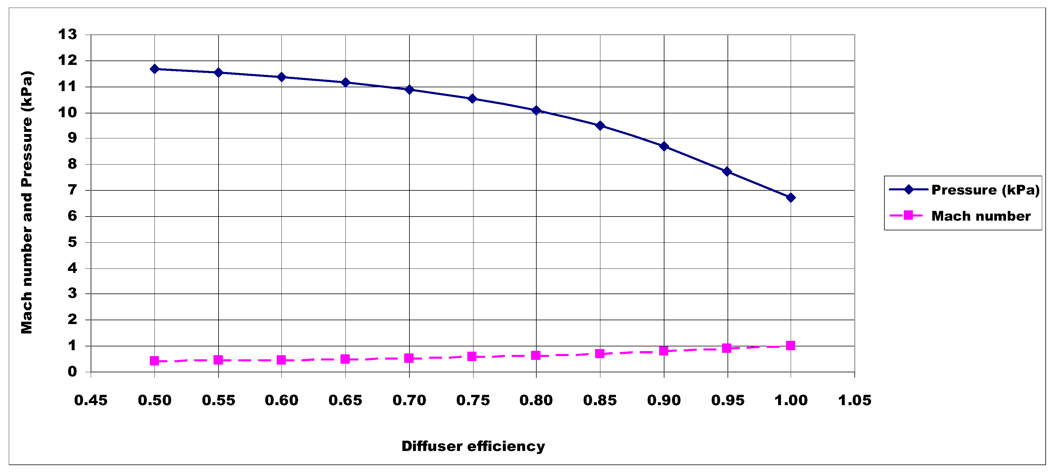
In this study, calculations were performed for diesel engine loads of 50%, 75%, 85% and 100%. The parameters were taken as evaporator temperature TE = 4 °C, condenser temperature TC = 50 °C, and boiler pressures PB = 0.2, 0.3, 0.4, 0.5, 0.6, 0.7, 0.8 and 0.9 MPa. Efficiencies are assumed to be 0.90, 0.85 and 0.90 for the nozzle, mixing and diffuser processes, respectively. Tolerance of convergence is set to 1%. Specific heat ratio, k, for superheated steam is assumed to be 1.3 in the superheated steam region.
Figure 4 shows that the variation of Mach number and pressure
versus diffuser efficiency for the optimum mixing section area at
Section 2. The results indicate that the pressure decreases as the diffuser efficiency increases at
Section 2. For diffuser efficiency,
, solving Equations (33) and (34) simultaneously yields
M2 = 0.7887 and
P2 = 8.697 kPa.
Figure 4.
Mach number and pressure
versus diffuser efficiency at
Section 2.
Figure 4.
Mach number and pressure
versus diffuser efficiency at
Section 2.
The boiler heat transfer rates depend on the engine load. As the engine load increases, the boiler heat increases. The boiler, condenser and evaporator heat transfer rates increase as the engine load increases.
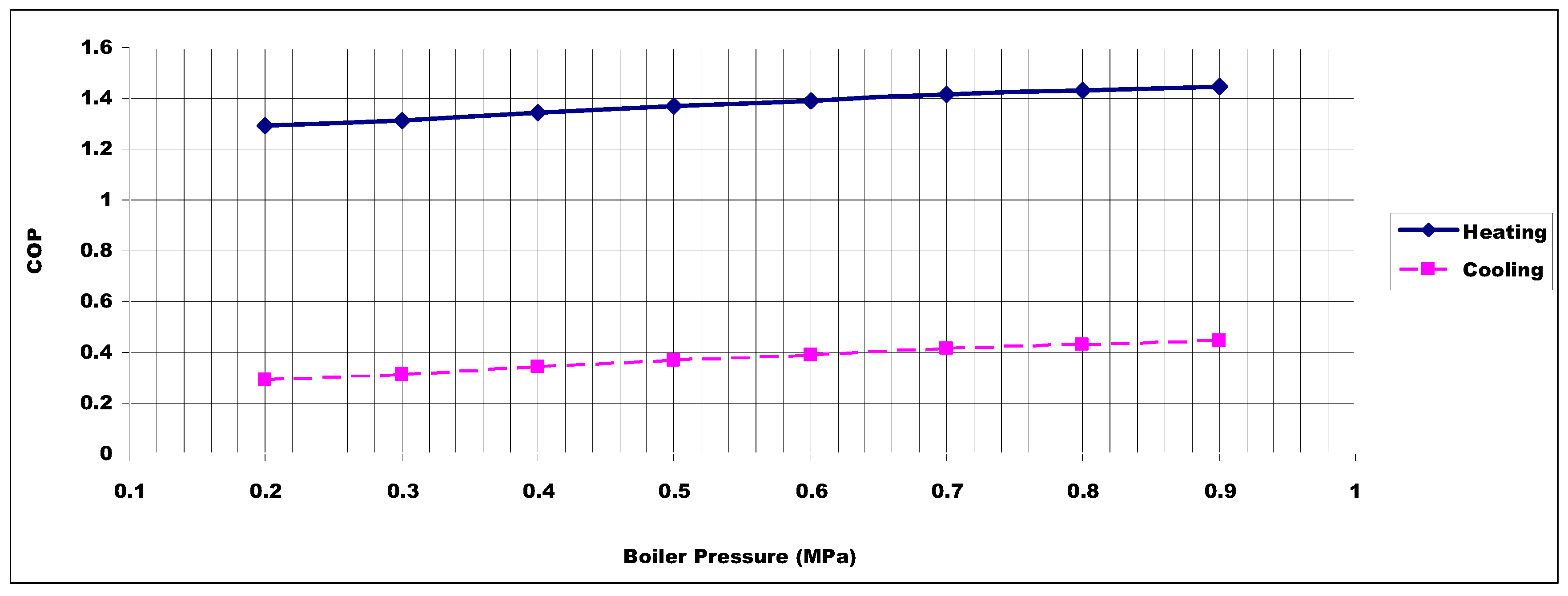
Figure 5 shows the COPs
versus the boiler pressure for heating and cooling given the boiler heat transfer rate.
Figure 5.
COPs versus boiler pressure.
Figure 5.
COPs versus boiler pressure.
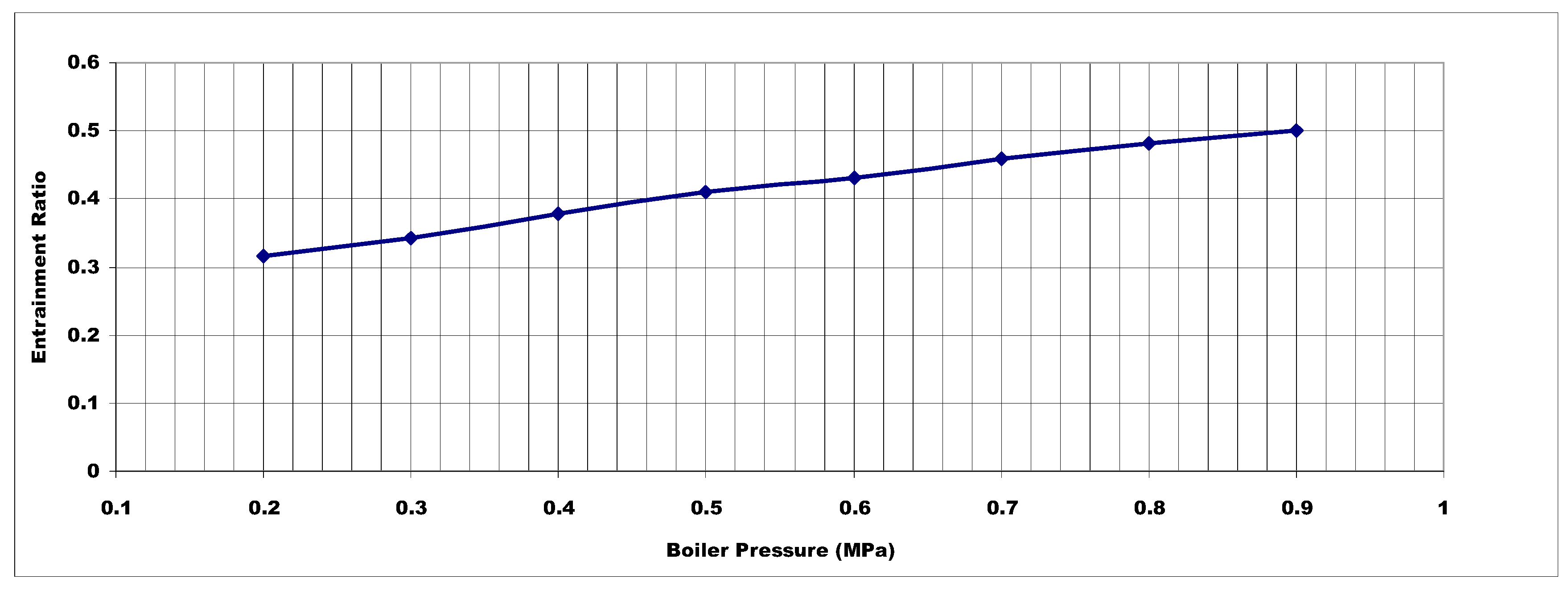
Figure 6 depicts the effect of boiler pressure on entrainment ratio for fixed evaporator and condenser temperatures. The entrainment ratio of the system increases with the increasing boiler pressure at given evaporator and condenser temperatures since there is more motive energy.
Figure 6.
Effect of boiler pressure on entrainment ratio.
Figure 6.
Effect of boiler pressure on entrainment ratio.
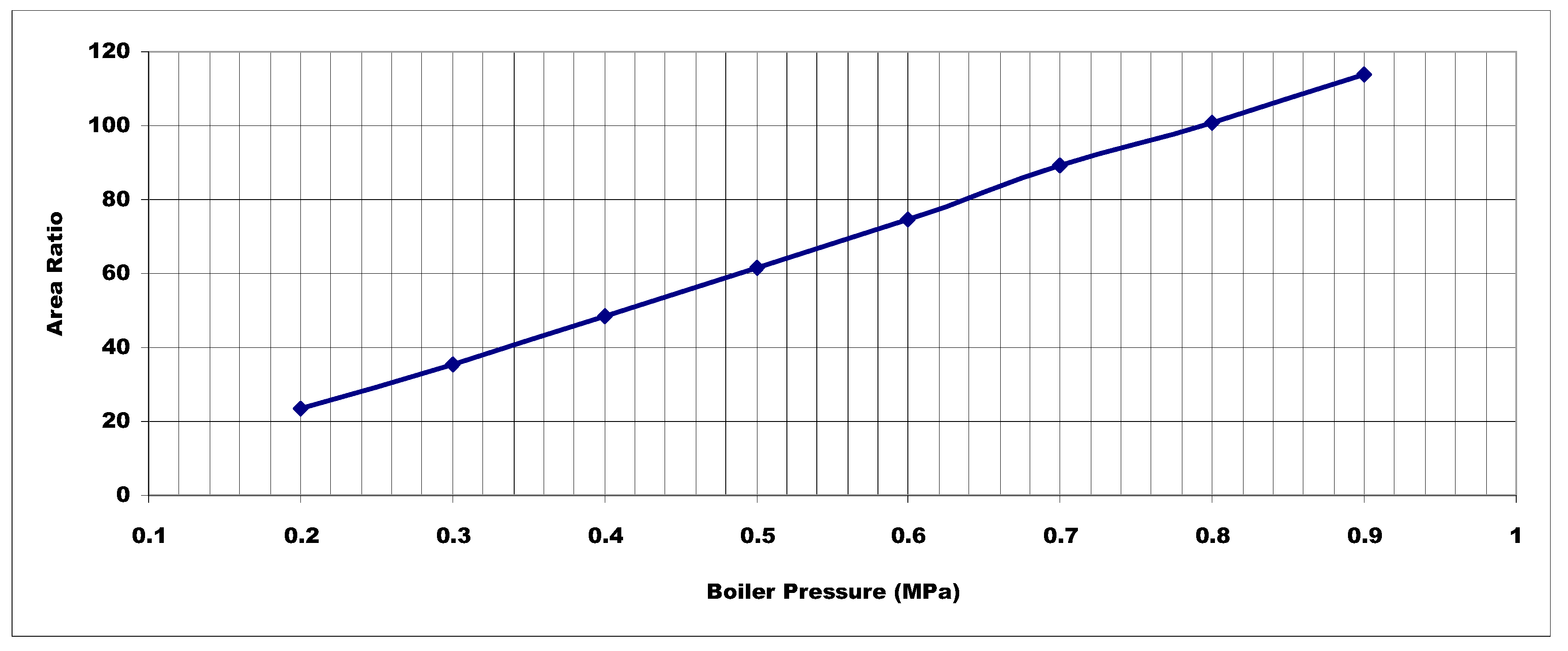
Figure 7 depicts the effect of boiler pressure on area ratio for fixed evaporator and condenser temperatures. The area ratio of the system increases with the increasing boiler pressure at given evaporator and condenser temperatures.
Figure 7.
Effect of boiler pressure on the area ratio.
Figure 7.
Effect of boiler pressure on the area ratio.
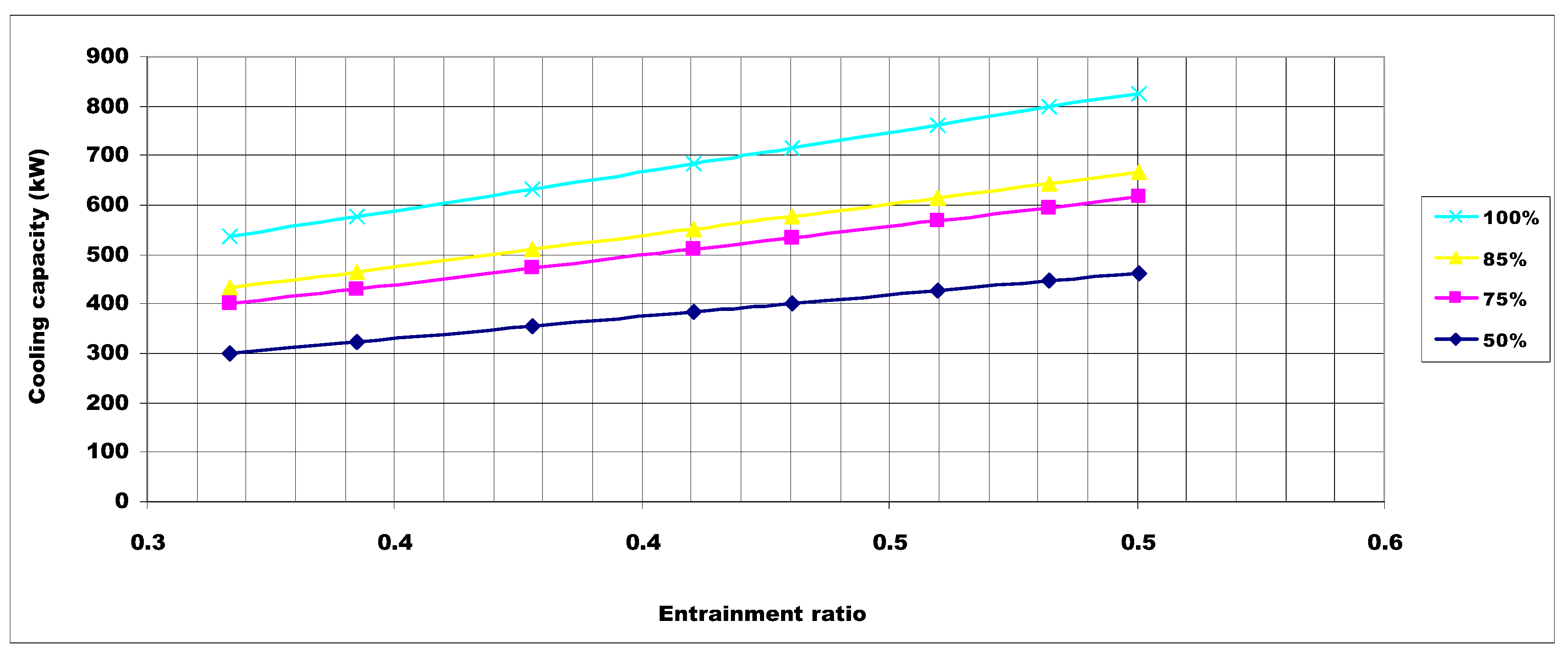
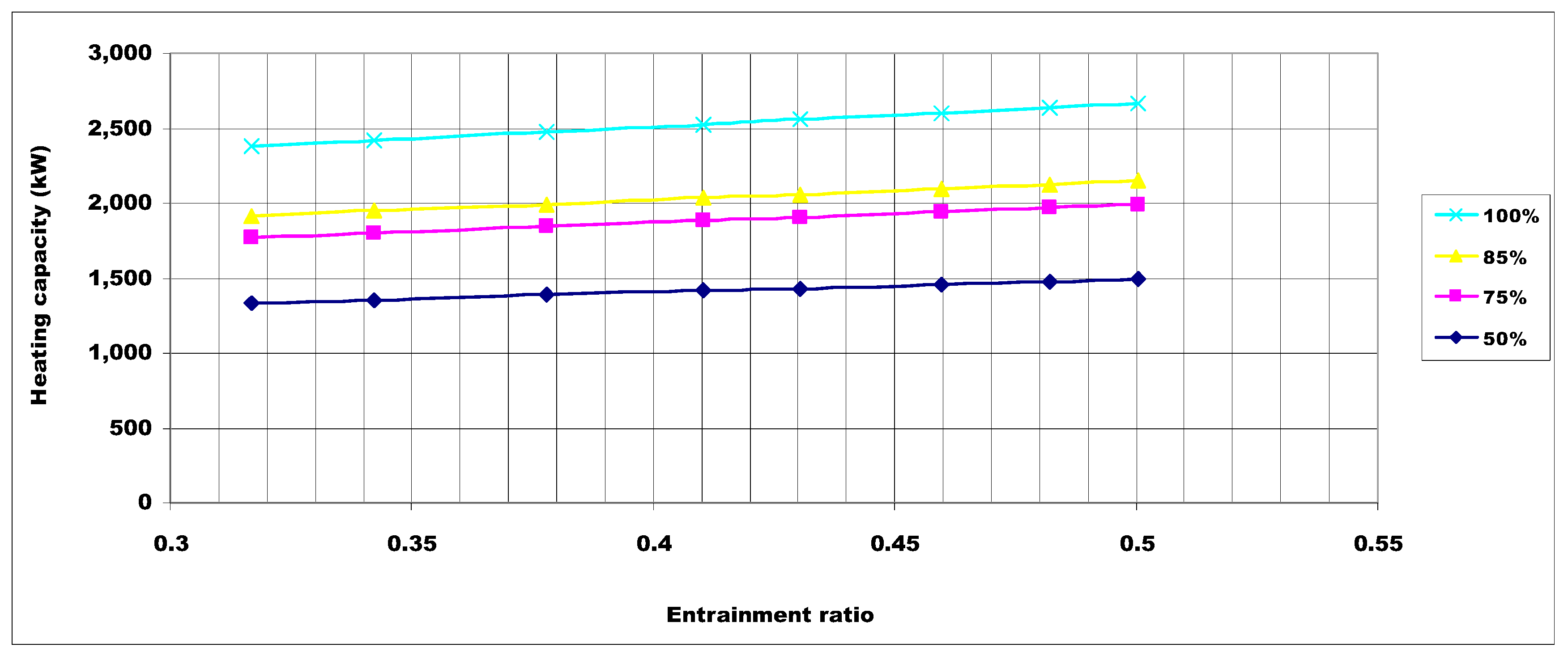
Figure 8 and
Figure 9 show the variation of cooling and heating capacity with change in entrainment ratio at a given engine load. The cooling and heating capacities of the system increase with the increase in entrainment ratio because the latter is directly proportional to the mass flow rate given to the evaporator.
Of course the mass flow rate of the steam, , decreases with the decreasing boiler heat transfer rate at a constant boiler pressure, condenser and evaporator temperatures. Therefore, COP, heating and cooling capacity decrease but the entrainment ratio and optimum mixing area ratio do not change. In this case, the exhaust gas boiler operating pressure is increased to achieve the needed heating and especially cooling capacity. The minimum recommended exhaust gas temperature can be kept as high as 285 °C depending on the sulphur content of the fuel oil in order to avoid any risk of hydrocarbon and ammonium sulphate condensation. Therefore, the boiler heat transfer rate decreases.
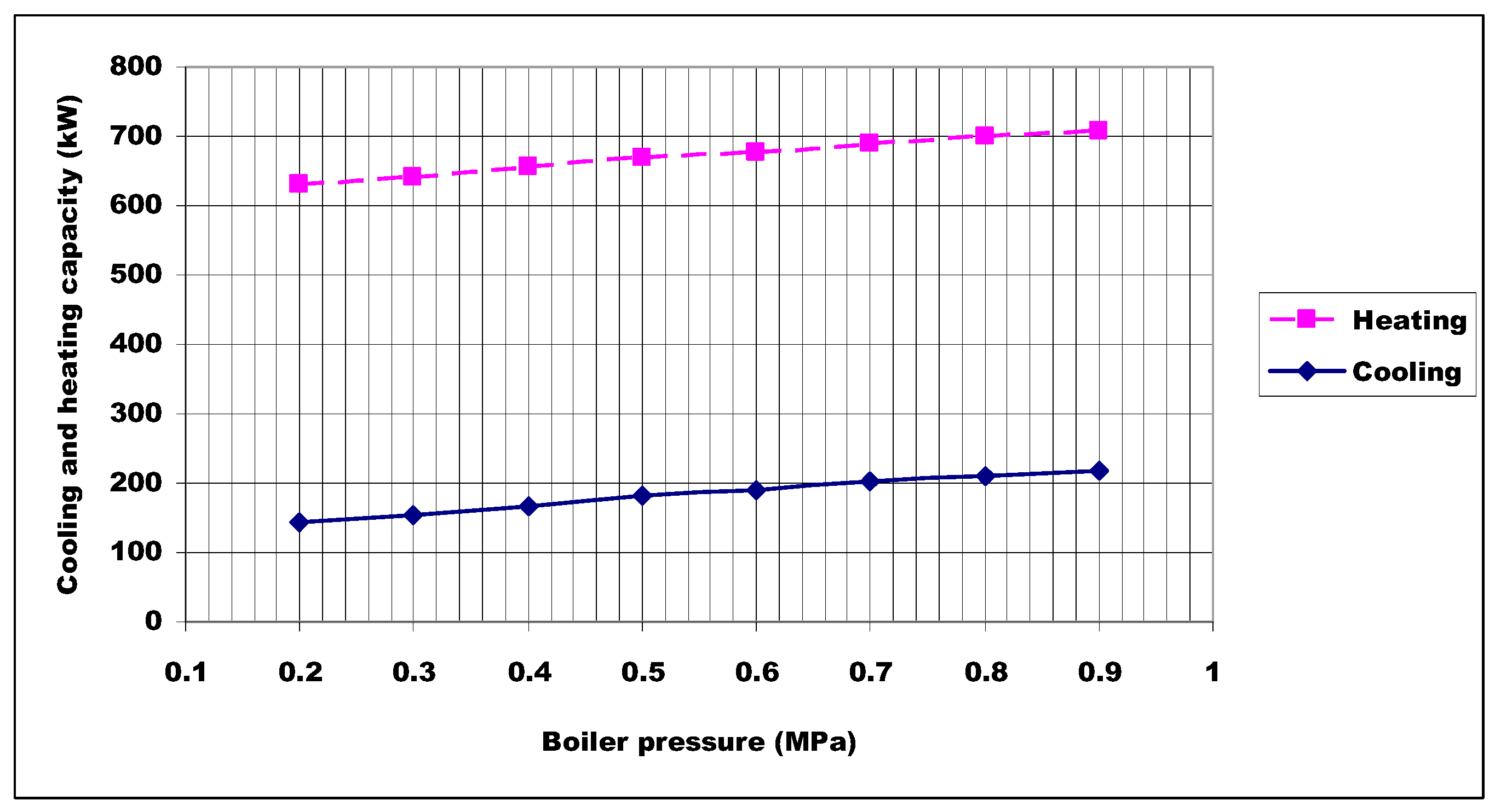
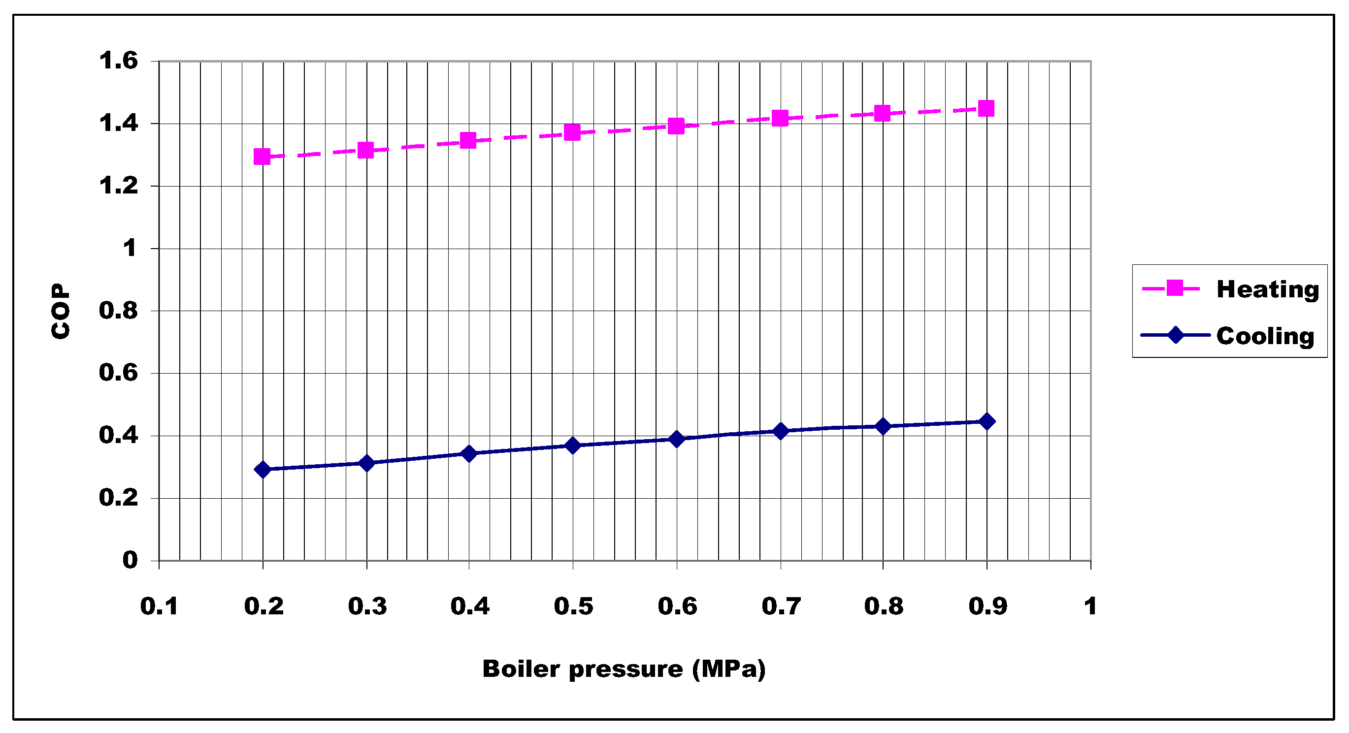
For example,
Figure 10 and
Figure 11 show the cooling and heating capacity and COP
versus boiler pressures for a boiler heat transfer rate of 488 kW,. For a boiler pressure of 0.2 MPa and the boiler heat transfer rate of 488 kW at given evaporator and condenser temperatures, the heating and cooling capacity are calculated to be 630.51 kW and 142.34 kW, respectively. COP is calculated to be 1.29 and 0.29 for the heating and cooling, respectively. The heating and cooling capacities can meet heating and cooling loads of the case naval surface ship. The residual heat, 486.51 kW in heating mode and 26.34 kW in cooling mode, is sent to hot water production in heating mode or to machine room cooling in cooling mode, respectively.
Figure 8.
Effect of entrainment ratio on cooling capacity.
Figure 8.
Effect of entrainment ratio on cooling capacity.
Figure 9.
Effect of entrainment ratio on heating capacity.
Figure 9.
Effect of entrainment ratio on heating capacity.
Figure 10.
Cooling and heating capacity versus boiler pressure.
Figure 10.
Cooling and heating capacity versus boiler pressure.
Figure 11.
COP versus boiler pressure.
Figure 11.
COP versus boiler pressure.
6.1. Verification of the Results
The entrainment ratios computed in the SER/SEHP system are compared with the theoretical results presented in references [
9,
10]. The numerical results for the entrainment ratios are compared in
Table 4. The difference in this comparison is acceptable. There is no experimental study based on the same working conditions of this study or similar ones.
Table 4.
Comparison between the entrainment ratios of presented system and the references.
Table 4.
Comparison between the entrainment ratios of presented system and the references.
| Boiler Pressure (P0), Temperatures of Condenser (TC) and Evaporator (TE) | This Study | Ref. [10] | Ref. [9] |
|---|
| Entrainment Ratio |
|---|
| P0 = 0.6 MPa, TC = 50 °C, TE = 4 °C | 0.430 | 0.43 | 0.45 |
| P0 = 0.8 MPa, TC = 50 °C, TE = 4 °C | 0.482 | - | 0.48 |
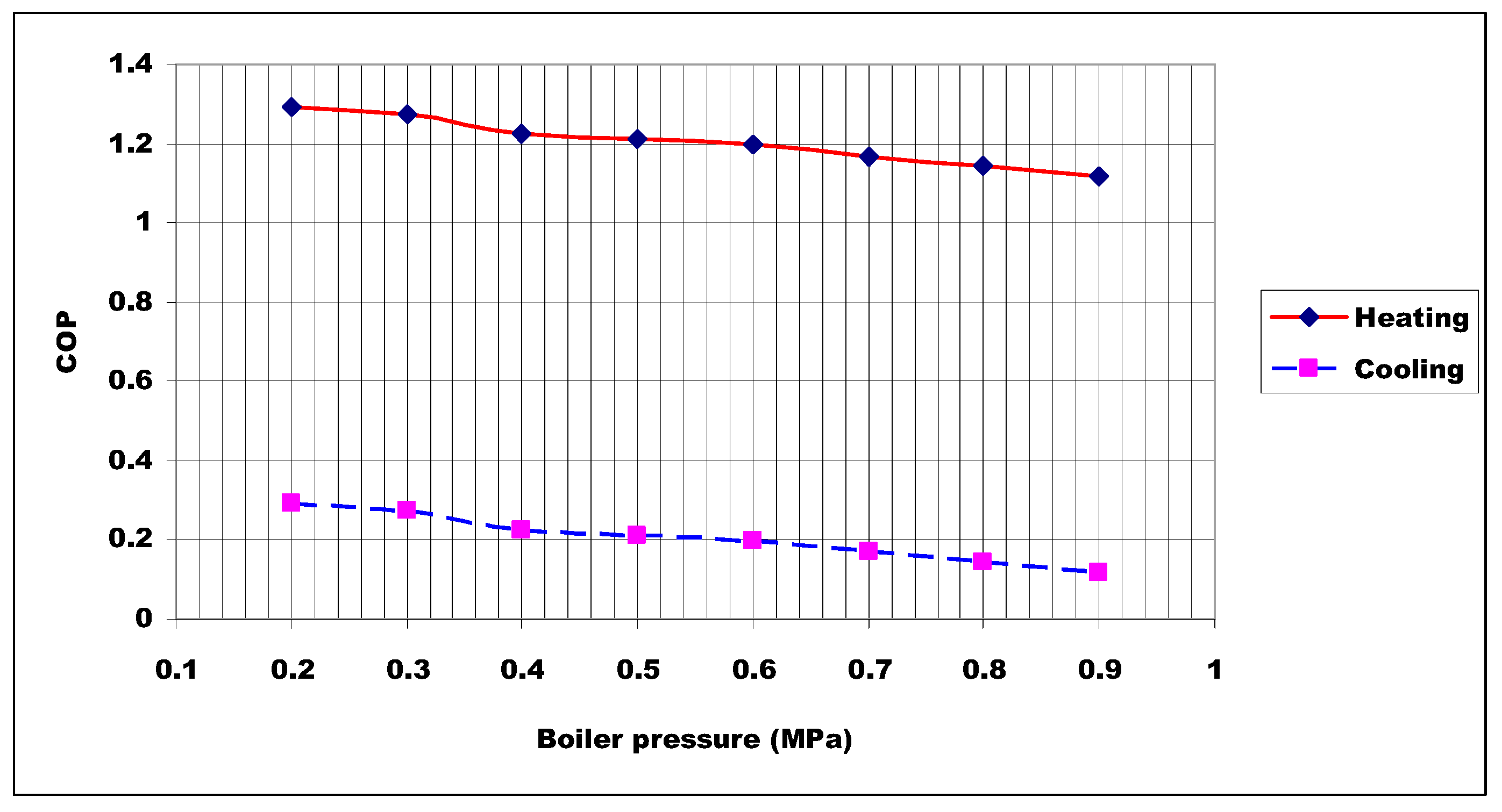
6.2. Off-Design Study
There is an optimum mixing constant section area A2 for each operating condition, yet an ejector heat pump doesn’t always operate at the design conditions. Therefore, an off-design study should be performed to determine the effect on COP for the SER/SEHP system. Heating and cooling capacity are calculated to be 1332.58 kW and 300.83 kW, respectively, for a boiler pressure of 0.2 MPa and engine load of 50% at given evaporator and condenser temperatures.
Figure 12.
COP versus boiler pressure for off-design.
Figure 12.
COP versus boiler pressure for off-design.
In the system operating at the exhaust gas boiler pressure of 0.2 MPa, the optimum area ratio is determined to be
. With the designed the area ratio (
), the COP values for heating and cooling are calculated and plotted in
Figure 12 for different boiler pressures.
6.3. Comparison Between an SER/SEHP System and Current System of Naval Ship
The electric power inputs for heating and cooling of the case naval ship are 37.5% and 15.1% of the naval ship’s installed diesel generator power, respectively. The saved F-76 diesel fuel consumption (SFC) for heating and cooling can be calculated as:
The electrical efficiency (
) for the diesel generator is 95%. Some values of the logistic fuel NATO F-76 are presented in
Table 5 [
2,
21,
22].
Table 5.
Values of the logistic fuel NATO F-76.
Table 5.
Values of the logistic fuel NATO F-76.
| Molecular Formula (Average) | C14.8H26.9 |
|---|
| Molecular weight | 205 |
| Sulphur content, wt.% (max) | 0.1 |
| Density, at 15 °C, kg·m−3 (max) | 876 |
| Fuel price, US$·gallon−1, (2015) | 3.69 |
| Lower heating value, Hu, kJ·kg−1 | 42,700 |
If an SEHP system is used instead of electric duct heaters in heating mode, 14,550 L of diesel fuel (US$14,511) can be saved and 38.30 tons of CO2 emissions reduced at the end of 1000 operating hours a year of a naval surface ship. If an SER system is used instead of seawater cooled chiller unit in cooling mode, 5837 L of diesel fuel (US$5822) can be saved and 15.36 tons of CO2 emissions reduced at the end of 1000 operating hours a year of a naval surface ship.
6.4. Comparison Between an SER/SEHP System and an H2O-LiBr AHP System
The reference system consists of an H
2O-LiBr AHP system driven exhaust heat of a 3000 kW diesel engine [
2].
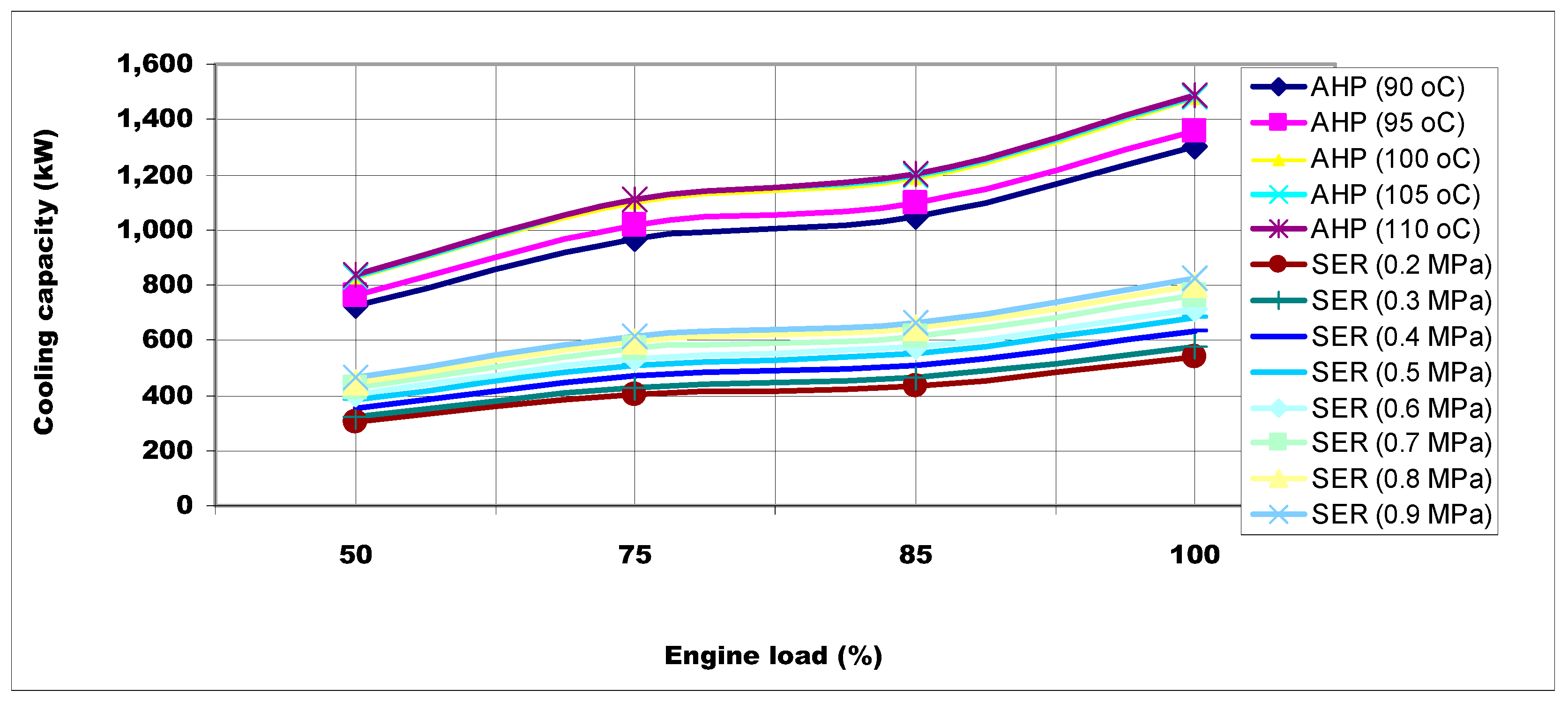
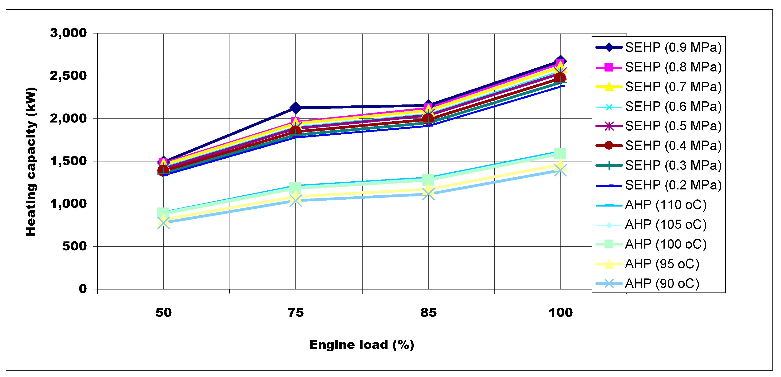
Figure 13 and
Figure 14 show cooling and heating capacities
versus engine load for the SER and SEHP system and an H
2O-LiBr AHP system. The cooling and heating capacities of the SER and SEHP and H
2O-LiBr AHP system increases with the increasing engine load at given evaporator and condenser temperatures. The cooling capacities of H
2O-LiBr AHP system are higher than SER but the heating capacities are lower than SEHP for the same engine with the same load.
Figure 13.
Cooling capacity versus engine load.
Figure 13.
Cooling capacity versus engine load.
Figure 14.
Heating capacity versus engine load.
Figure 14.
Heating capacity versus engine load.
6.5. Comparison between an SER/SEHP System and a VCHP System
The reference system in this case consists of a conventional diesel generator, which provides electricity and heat, and a vapour-compression heat pump (VCHP), which produces heating and cooling. VCHPs generally have COPs of 2–4 and deliver 2–4 times more energy than they consume. The electric motor of the compressor in a VCHP is fed by a diesel generator set on board the ship. As the energy for the entire naval ship’s electrical load is produced from diesel generator sets, each electrical load directly affects the overall fuel economy and emissions.
Fuel consumption and CO2 emissions decrease to produce the same amount of power given by a VCHP system when an SER/SEHP system is used. As the SER/SEHP system is assumed to replace the VCHP system, the results of the system studies will depend on the COP of the VCHP.
Based on the engine load, the heating demand is assumed to be 1332.58, 1774.36, 1916.14 and 2379.16 kW, the cooling demand is assumed to be 300.83, 400.56, 432.57 and 537.10 kW, and the COP is assumed to be 2, 3 and 4 for the VCHP. The amounts of cooling and heating produced by the SER/SEHP in each system can be regarded to correspond to electricity saving. The saving is calculated by estimating fuel and the electricity input needed to produce the same heating and cooling effect using the VCHP. The calculations are performed with COPs of 2, 3 and 4 for the VCHP.
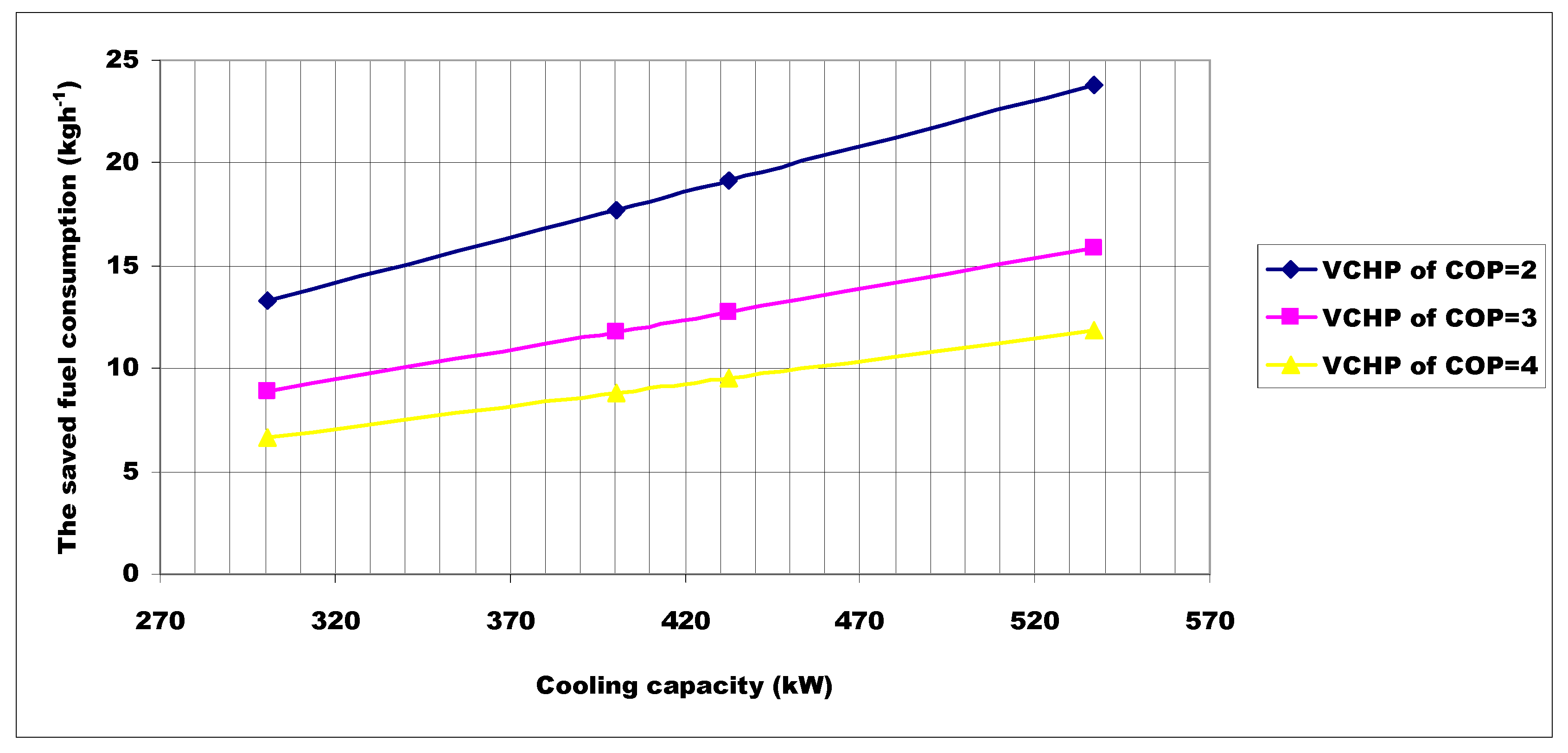
Figure 15 and
Figure 16 present the SFC
versus heating and cooling capacities for a boiler pressure of 0.2 MPa.
Figure 15.
SFC versus heating capacity.
Figure 15.
SFC versus heating capacity.
Figure 16.
SFC versus cooling capacity.
Figure 16.
SFC versus cooling capacity.
At the end of 1000 operating hours a year of a naval surface ship, the SER/SEHP system can use more than 99.5% less electricity compared with the vapour-compression heat pump for HVAC. It can save 33,712–120,447 L of diesel fuel in the heating cycle and 7581–27,139 L of diesel fuel in the cooling cycle depending on the engine load and COP of the vapour-compression heat pump.
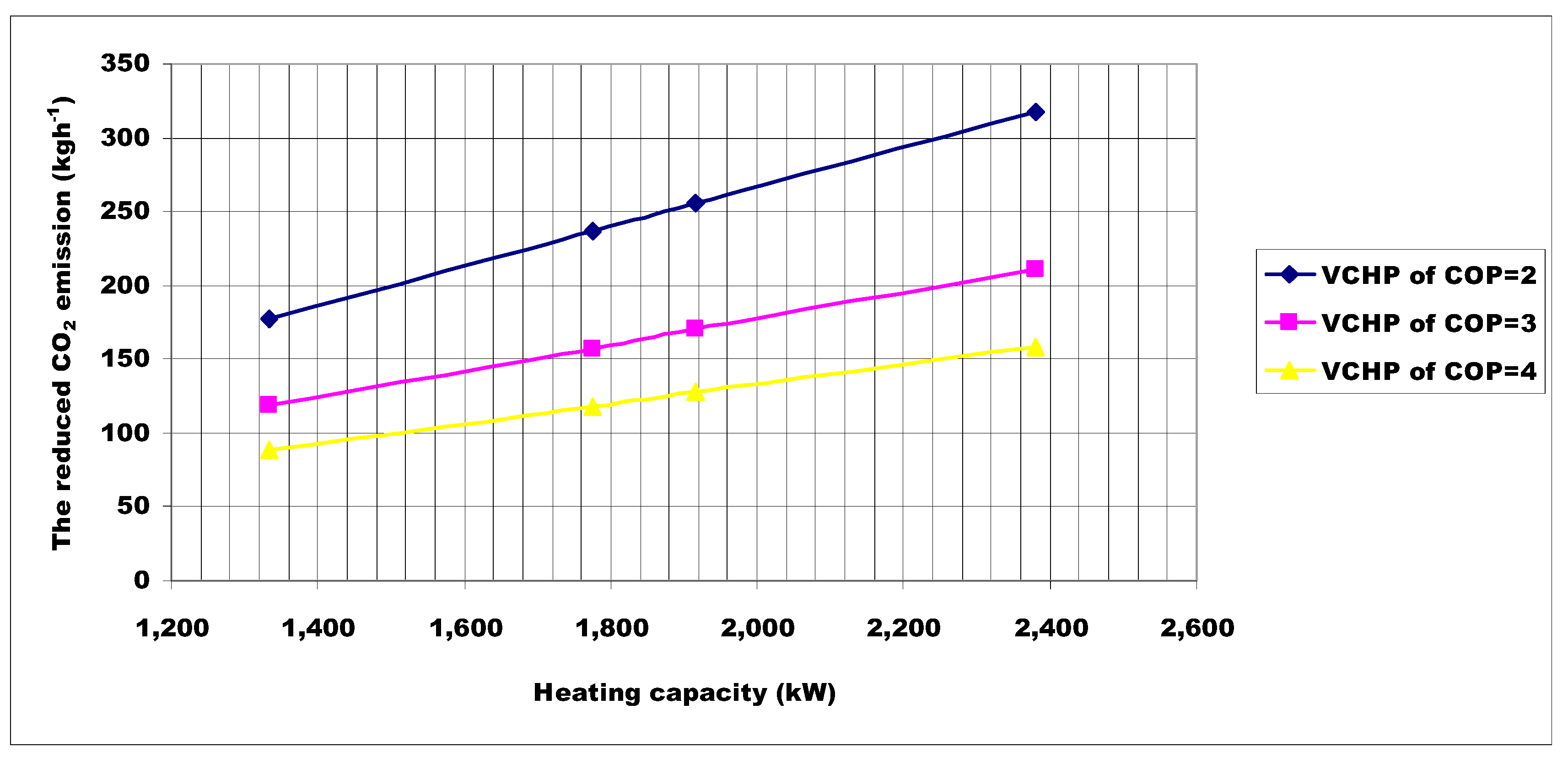
Figure 17 and
Figure 18 show the reduced CO
2 emission
versus heating and cooling capacities for a boiler pressure of 0.2 MPa. At the end of 1000 operating hours a year of a naval surface ship, the AHP system can improve the ship’s green profile because it will reduce its annual CO
2 emissions by 88.74–317.05 tons in the heating cycle and 19.95–71.43 tons in the cooling cycle depending on the engine load and COP of the vapour-compression heat pump.
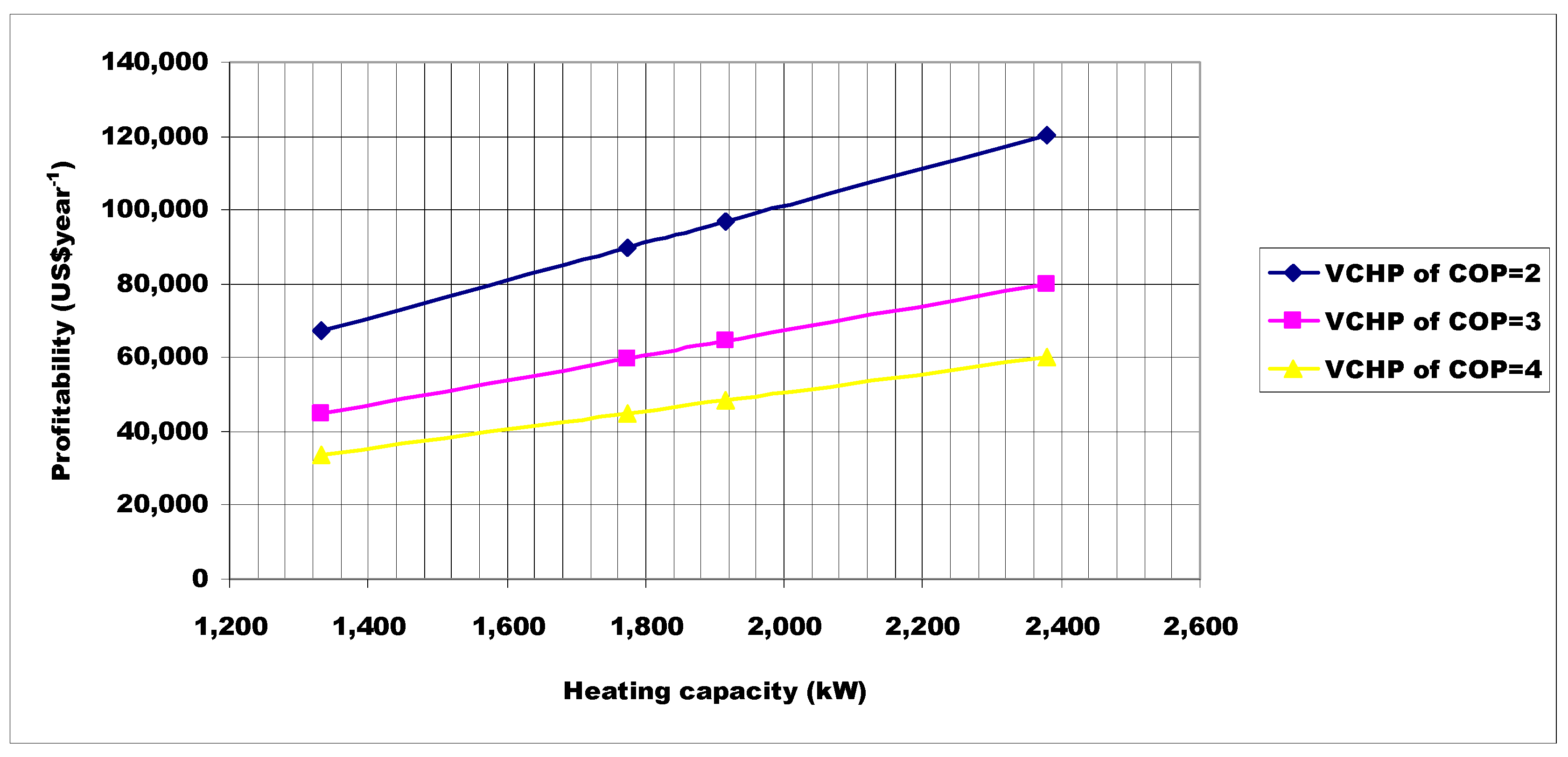
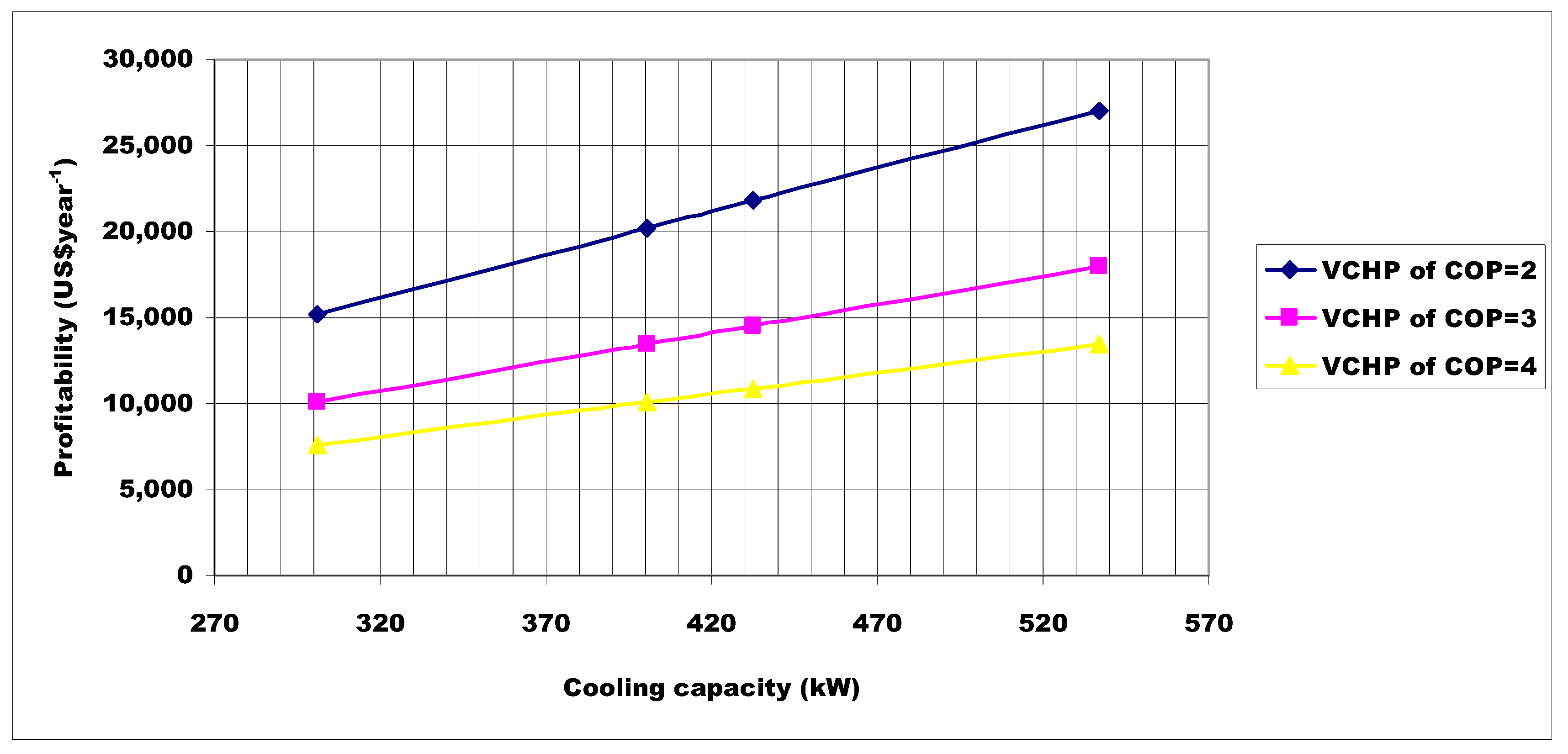
Figure 19 and
Figure 20 show the profitability plotted against the heating and cooling capacities, respectively. The fuel price is set to US$3.69 gallon
−1 and the operating hours are 1000 h a year. In this case, the COPs used for the VCHP are 2, 3 and 4. The SEHP system can provide an annual energy savings of US$33,621–US$120,122 and the SER system can provide an annual energy savings of US$7561–US$27,065.
Figure 17.
Reduced CO2 emissions versus heating capacity.
Figure 17.
Reduced CO2 emissions versus heating capacity.
Figure 18.
Reduced CO2 emissions versus cooling capacity.
Figure 18.
Reduced CO2 emissions versus cooling capacity.
Figure 19.
Profitability of the SEHP system as a function of heating capacity.
Figure 19.
Profitability of the SEHP system as a function of heating capacity.
Figure 20.
Profitability of the SER system as a function of cooling capacity.
Figure 20.
Profitability of the SER system as a function of cooling capacity.
7. Conclusions
A seawater cooled SER/SEHP system for a naval surface ship was designed and thermodynamically analysed. The SER/SEHP system was compared with those of a current system in a case naval ship, an H2O–LiBr AHP system and a VCHP system in a case naval surface ship. The dual use of ejector technology to produce heating and cooling on board a naval ship was investigated.
The off-design study estimated the COPs were 0.29–0.11 for the cooling mode and 1.29–1.11 for the heating mode, depending on the pressure of the exhaust gas boiler at off-design conditions. In the system operating at the exhaust gas boiler pressure of 0.2 MPa, the optimum area ratio obtained was 23.30.
The results show that the seawater-cooled SER/SEHP system not only meets the actual cooling and heating and loads of the case naval surface ship, but also provides more. The SER system is particularly attractive in applications that have a cooling demand and a source of heat, such as naval surface ships. The SEHP system is needed for the HVAC as waste heat from a running ship engine may be sufficient to provide enough heat to meet the heating load.
The results show that SER/SEHP is an environmentally friendly way to produce heating and cooling as it reduces the use of an electrically driven heat pump in the energy system and thus global CO2 emissions. Moreover, as water can be used as the refrigerant in SER/SEHP, the problem of environmentally harmful refrigerants used in VCHP is avoided.
Compared with current system of a case naval ship, SER and SEHP system have the advantages of lower energy consumption, CO2 emissions and EEDI. Despite the low COP values obtained in this study, the SEHP operating in the heating mode offers better performance than electrical resistance type heating.
Compared with an AHP system, SER and SEHP system have the advantages of lower cost, simplicity, and minimal maintenance, even though its efficiency is still relatively low. More importantly, an absorption heat pump is prone to corrosion and occupies a large installation space, while an ejector heat pump is convenient and compact.
Compared with a VCHP system, SER and SEHP system have the advantages of lower of energy consumption, CO2 emissions and EEDI. More importantly, the naval ship's susceptibility can be dramatically reduced by lowering infrared and acoustic signature. In future studies, variable area ejectors for seawater-cooled SER/SEHP system application should be investigated.


