
Energetic and Exergetic Analysis of a Heat Exchanger Integrated in a Solid Biomass-Fuelled Micro-CHP System with an Ericsson Engine

Abstract
:1. Introduction
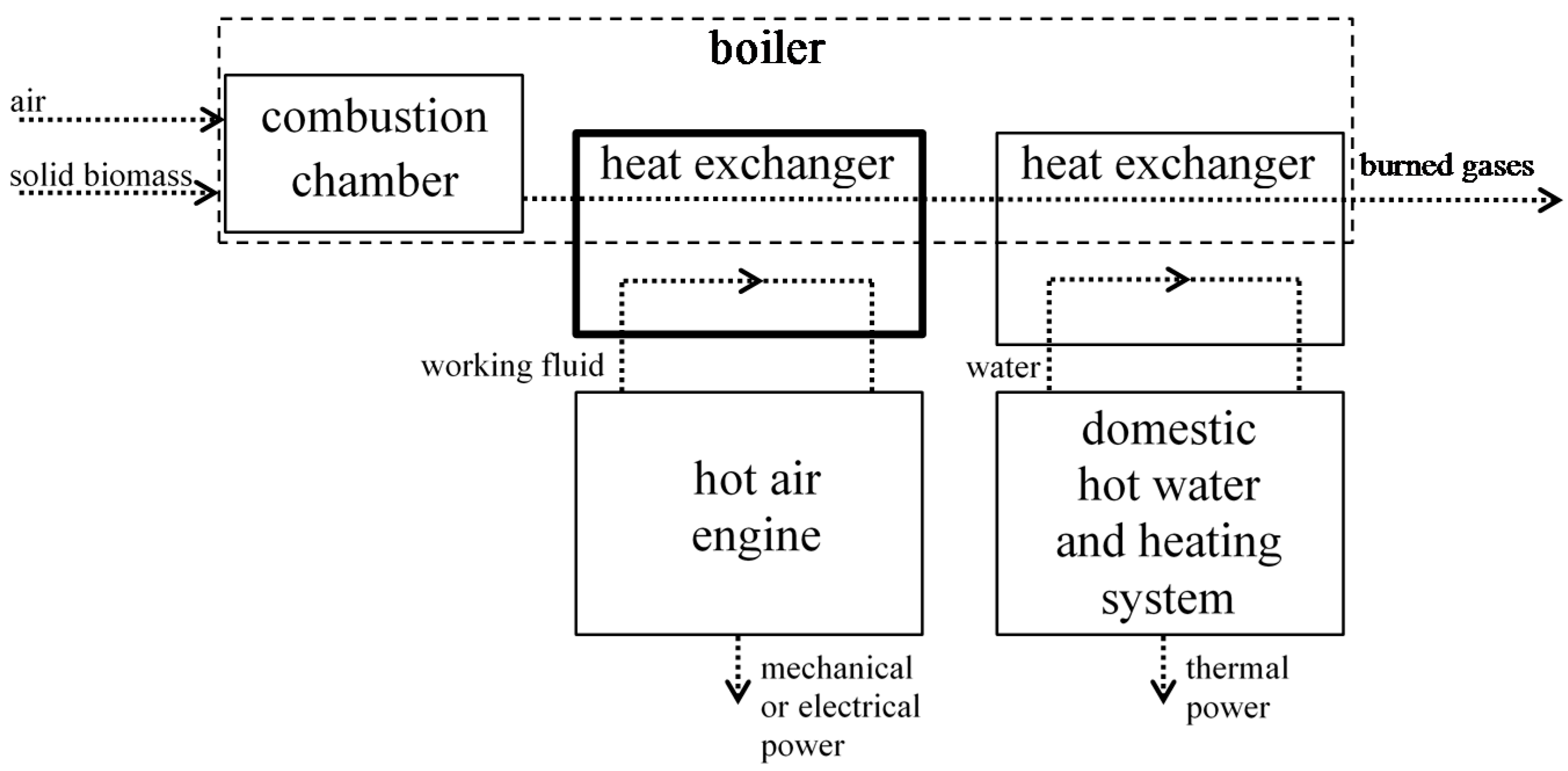
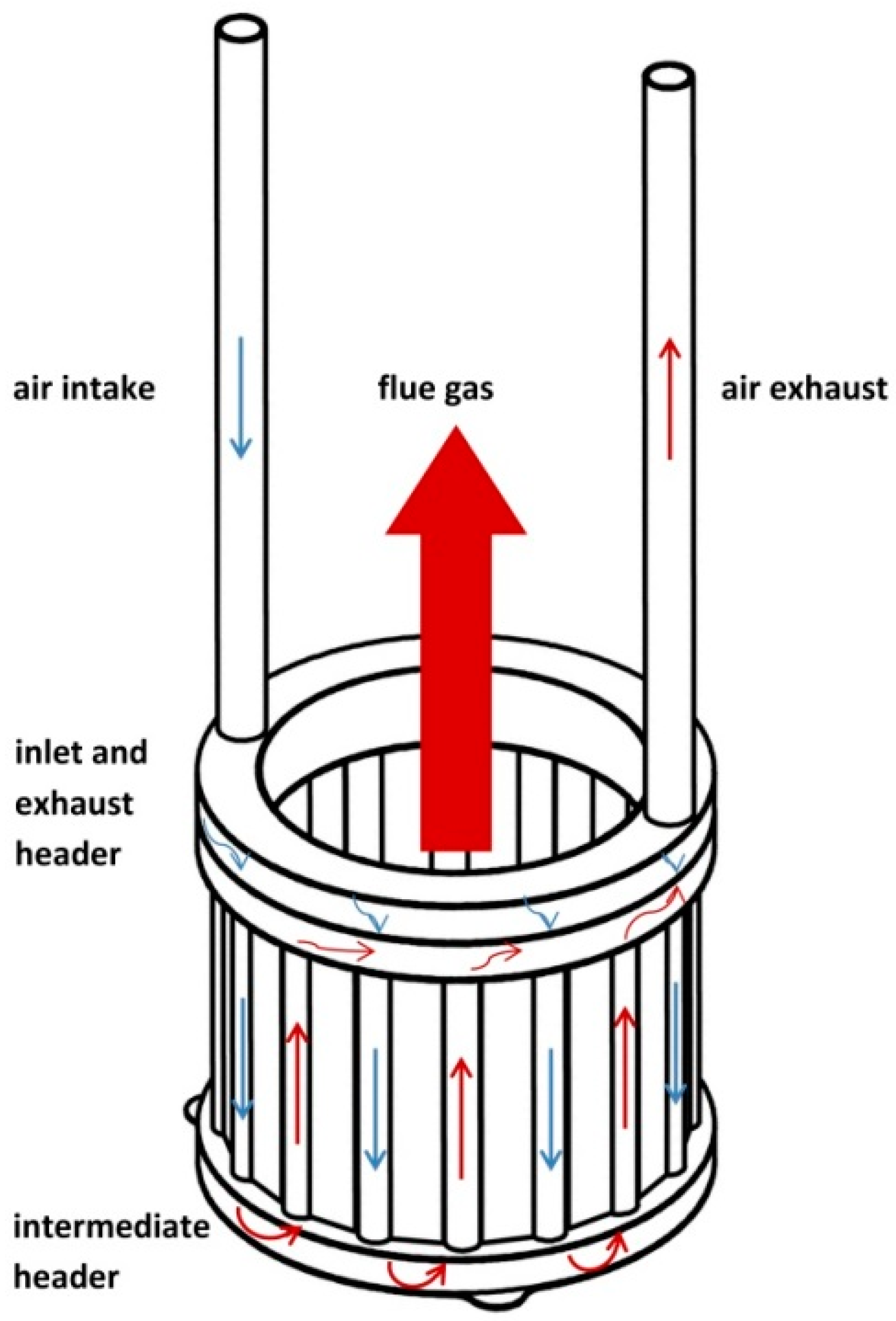
2. Configuration of the Heat Exchanger Associated to the Biomass-Fuelled Micro-CHP Unit
3. Materials and Methods
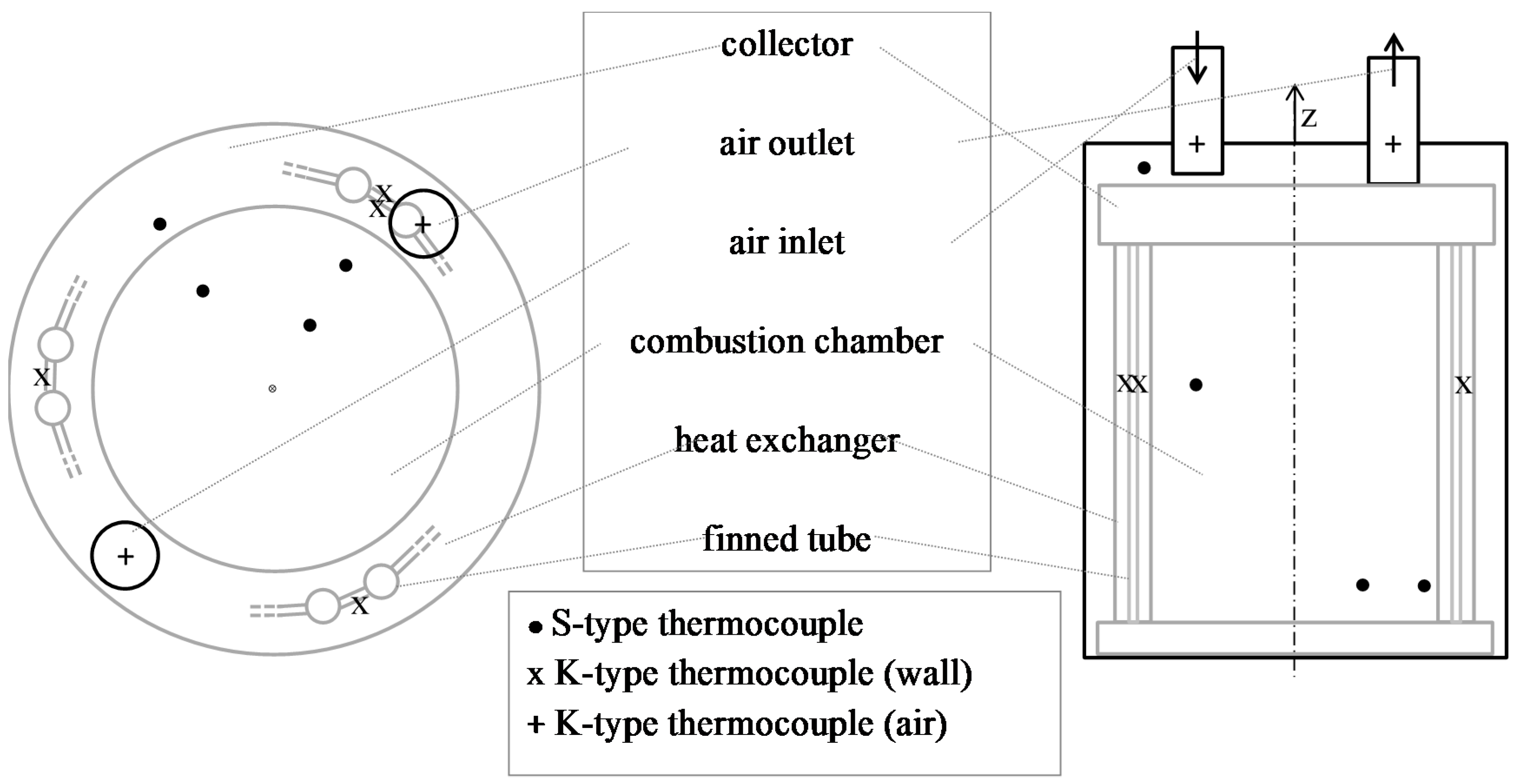
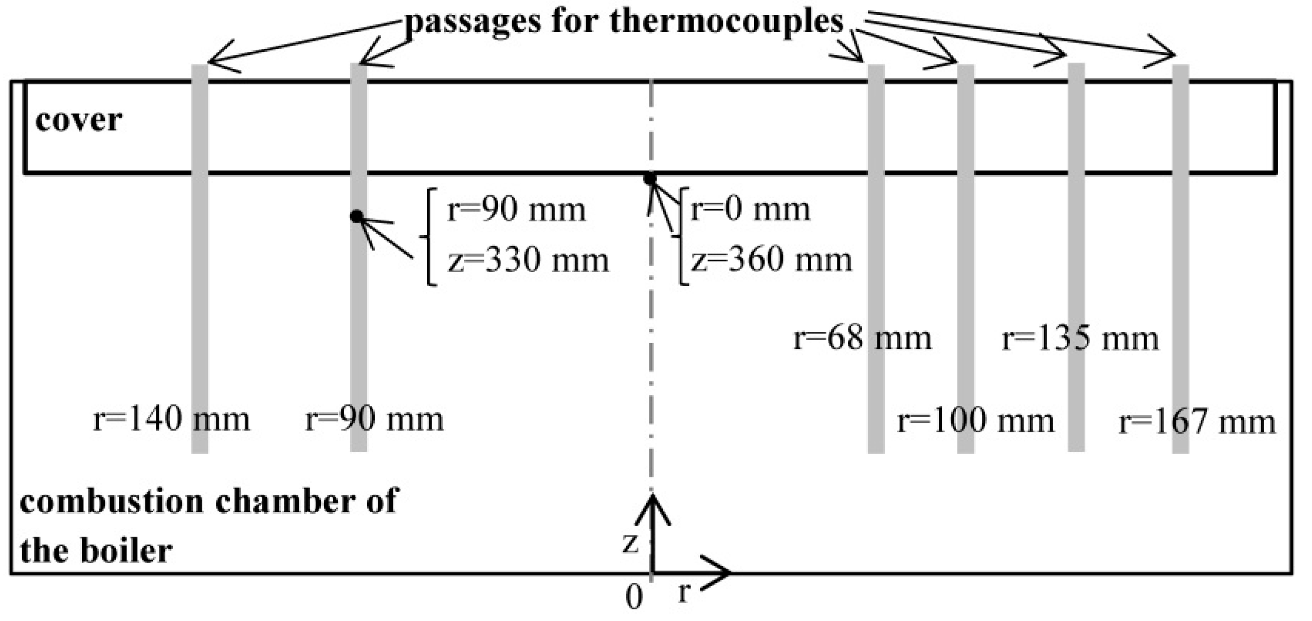
3.1. Heat Exchanger Instrumentation: Metrology and Calibration
3.2. Experimental Methodology
4. Modelling of the Heat Exchanger Inserted in the Biomass-Fuelled Micro-CHP System
4.1. Energetic Model of the Heat Exchanger
4.2. Exergetic Model of the Heat Exchanger Inserted in the Biomass-Fuelled Micro-CHP System
4.2.1. Exergetic Balances
4.2.2. Exergy Flux of Solid Biomass Fuel
4.2.3. Exergetic Performances of the Heat Exchanger Ha: Exergetic Efficiency and Exergetic Effectiveness
5. Results and Discussion
5.1. Energetic Study of the Heat Exchanger: Comparison of Theoretical and Experimental Results
5.2. Performances of the Heat Exchanger Integrated to The Solid Biomass-Fuelled Micro-CHP System
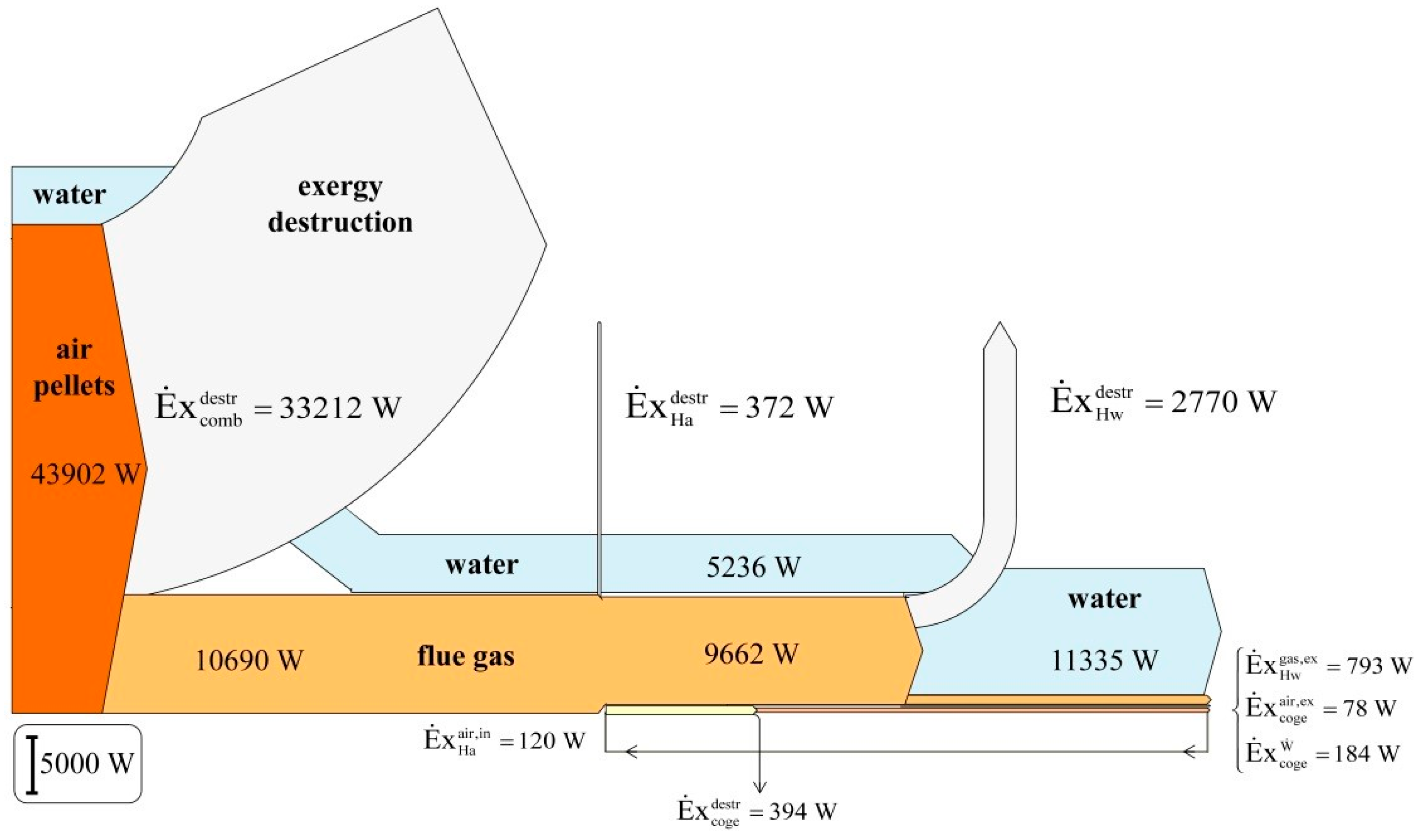
5.3. Exergetic Flux and Exergy Destruction in the Micro-CHP System
- For the gas-water heat exchanger (Hw): mass flow rate of water = 0.5 kg/s, mass flow rate of gas = 0.022 kg/s, water inlet temperature = 60 °C, water outlet temperature = 80 °C, gas outlet temperature = 180 °C.
- For the combustion chamber (comb): mass flow rate of pellet = 0.002 kg/s, mass flow rate of air = 0.020 kg/s, air inlet temperature = 20 °C, outlet gas temperature = 800 °C.
- For the Ericsson engine (coge): mass flow rate of air = 0.0019 kg/s, air inlet temperature = 20 °C, air outlet temperature = 198 °C.
6. Conclusions
Acknowledgments
Author Contributions
Conflicts of Interest
References
- Crema, L.; Alberti, F.; Bertaso, A.; Bozzoli, A. Development of a pellet boiler with Stirling engine for m-CHP domestic application. Energy Sustain. Soc. 2011, 1, 1–11. [Google Scholar] [CrossRef]
- Thiers, S.; Aoun, B.; Peuportier, B. Experimental characterization, modeling and simulation of a wood pellet micro-combined heat and power unit used as a heat source for a residential building. Energy Build. 2010, 42, 896–903. [Google Scholar] [CrossRef]
- Biedermann, F.; Carlsen, H.; Schöch, M.; Obernberger, I. Operating experiences with a small-scale CHP pilot plant based on a 35 kWel hermetic four cylinder Stirling engine for biomass fuels. In Proceedings of the 11th International Stirling Engine Conference, Rome, Italy, 19–21 November 2003; pp. 19–21.
- Podesser, E. Electricity production in rural villages with a biomass Stirling engine. Renew. Energy 1999, 16, 1049–1052. [Google Scholar] [CrossRef]
- Qiu, K.; Hayden, A.C.S. Integrated thermoelectric and organic Rankine cycles for micro-CHP systems. Appl. Energy 2012, 97, 667–672. [Google Scholar] [CrossRef]
- Alanne, K.; Laukkanen, T.; Saari, K.; Jokisalo, J. Analysis of a wooden pellet-fueled domestic thermoelectric cogeneration system. Appl. Therm. Eng. 2014, 63, 1–10. [Google Scholar] [CrossRef]
- Creyx, M.; Delacourt, E.; Morin, C.; Desmet, B.; Peultier, P. Energetic optimization of the performances of a hot air engine for micro-CHP systems working with a Joule or an Ericsson cycle. Energy 2013, 49, 229–239. [Google Scholar] [CrossRef]
- Bell, M.A.; Partridge, T. Thermodynamic design of a reciprocating Joule cycle engine. Proc. Inst. Mech. Eng. Part A 2003, 217, 239–246. [Google Scholar] [CrossRef]
- Al-Attab, K.A.; Zainal, Z.A. Performance of high-temperature heat exchangers in biomass fuel powered externally fired gas turbine systems. Renew. Energy 2010, 35, 913–920. [Google Scholar] [CrossRef]
- Gaderer, M.; Gallmetzer, G.; Spliethoff, H. Biomass fired hot air gas turbine with fluidized bed combustion. Appl. Therm. Eng. 2010, 30, 1594–1600. [Google Scholar] [CrossRef]
- McDonald, C.F. Recuperator considerations for future higher efficiency microturbines. Appl. Therm. Eng. 2003, 23, 1463–1487. [Google Scholar] [CrossRef]
- El-Ehwany, A.A.; Hennes, G.M.; Eid, E.I.; El-Kenany, E. Experimental investigation of the performance of an elbow-bend type heat exchanger with a water tube bank used as a heater or cooler in alpha-type Stirling machines. Renew. Energy 2011, 36, 488–497. [Google Scholar] [CrossRef]
- Carlsen, H.; Marinitsch, G.; Schöch, M.; Obernberger, I. Development of a hot heat exchanger and a cleaning system for a 35 kW hermetic four cylinder Stirling engine for solid biomass fuels. In Proceedings of the 12th International Stirling Engine Conference and Technology Exhibition, Durham, UK, 7–9 September 2005.
- Bonnet, S.; Alaphilippe, M.; Stouffs, P. Energy, exergy and cost analysis of a micro-cogeneration system based on an Ericsson engine. Int. J. Therm. Sci. 2005, 44, 1161–1168. [Google Scholar] [CrossRef]
- Creyx, M.; Delacourt, E.; Morin, C.; Desmet, B.; Peultier, P. Modelling of the heat transfers in a flue gas-air heat exchanger implanted in a solid biomass fuelled micro-combined heat and electrical power system. In Proceedings of the Eurotherm Seminar No 96, Brussels, Belgium, 17–18 September 2013.
- Lalot, S. The NTU-Effectiveness Method; Nova Science Publishers: New York, NY, USA, 2011. [Google Scholar]
- Tessé, L.; Lamet, J.-M. Radiative transfer modeling developed at Onera for numerical simulations of reactive flows. Aerosp. Lab 2011, 2, 1–19. [Google Scholar]
- Rivière, P.; Soufiani, A. Updated band model parameters for H2O, CO2, CH4 and CO radiation at high temperature. Int. J. Heat Mass Transf. 2012, 55, 3349–3358. [Google Scholar] [CrossRef]
- Chase, M.W., Jr. (Ed.) NIST-JANAF Themochemical Tables, Fourth Edition. J. Phys. Chem. Ref. Data Monogr. 1998, 9, 1–1951.
- Song, G.; Xiao, J.; Zhao, H.; Shen, L. A unified correlation for estimating specific chemical exergy of solid and liquid fuels. Energy 2012, 40, 164–173. [Google Scholar] [CrossRef]
- Al-Sulaiman, F.A.; Hamdullahpur, F.; Dincer, I. Greenhouse gas emission and exergy assessments of an integrated organic Rankine cycle with a biomass combustor for combined cooling, heating and power production. Appl. Therm. Eng. 2011, 31, 439–446. [Google Scholar] [CrossRef]
- Szargut, J. Exergy Method: Technical and Ecological Applications; WIT Press: Southampton, UK; Boston, MA, USA, 2005. [Google Scholar]
- Szargut, J.; Morris, D.R.; Steward, F.R. Exergy Analysis of Thermal, Chemical, and Metallurgical Processes; Hemisphere: New York, NY, USA, 1988. [Google Scholar]
- Shieh, J.H.; Fan, L.T. Estimation of Energy (Enthalpy) and Exergy (Availability) Contents in Structurally Complicated Materials. Energy Sources 1982, 6, 1–46. [Google Scholar] [CrossRef]
- Wu, S.Y.; Yuan, X.F.; Li, Y.R.; Xiao, L. Exergy transfer effectiveness on heat exchanger for finite pressure drop. Energy 2007, 32, 2110–2120. [Google Scholar] [CrossRef]
- Lalot, S.; Florent, P.; Lang, S.K.; Bergles, A.E. Flow maldistribution in heat exchangers. Appl. Therm. Eng. 1999, 19, 847–863. [Google Scholar] [CrossRef]
- Bergman, T.L.; Lavine, A.S.; Incropera, F.P.; DeWitt, D.P. Fundamentals of Heat and Mass Transfer; Wiley: New York, NY, USA, 2011. [Google Scholar]


| Parameter | Adjusted Value | Maximum Variation during a Test of 10 min |
|---|---|---|
| Air volume flow rate | 2.5, 5, 7.5, 10 Nm3/h | 4.3% |
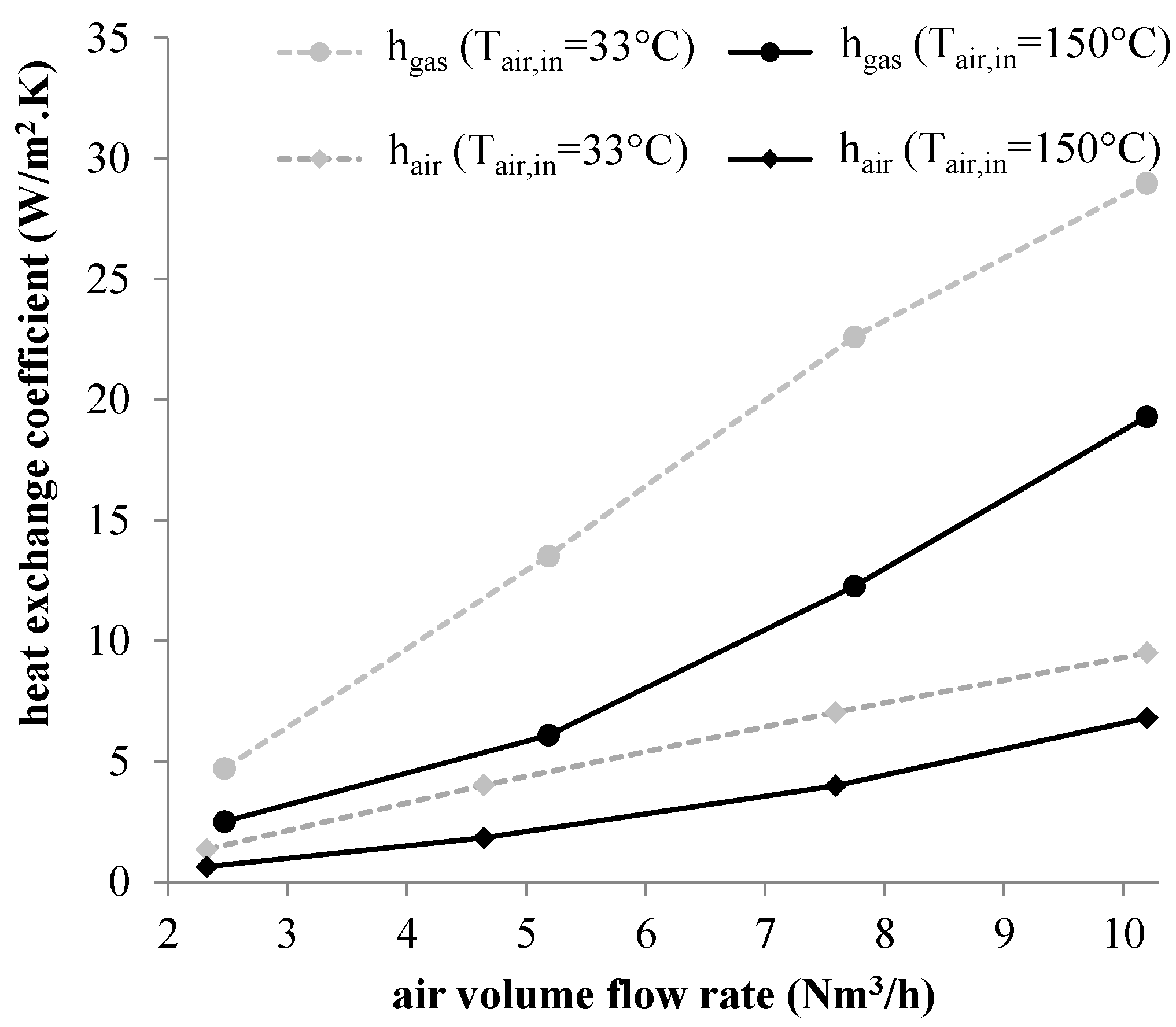
| Inlet air temperature | 33, 150 °C | – |
| Inlet flue gas temperature | 818–980 °C | 9.4% |
| Test duration | 10 min | – |
| Sampling frequency | 1 Hz | – |
| Air Flow Rate | 2.5 Nm3/h | 5 Nm3/h | 7.5 Nm3/h | 10 Nm3/h | ||||
|---|---|---|---|---|---|---|---|---|
| Inlet air temperature | 33 °C | 150 °C | 33 °C | 150 °C | 33 °C | 150 °C | 33 °C | 150 °C |
| Inlet flue gas temperature | 980 °C | 818 °C | 955 °C | 870 °C | 954 °C | 904 °C | 924 °C | 962 °C |
| Wall temperature | 737 °C | 638 °C | 729 °C | 666 °C | 719 °C | 684 °C | 693 °C | 717 °C |
| Outlet air temperature | 232 °C | 194 °C | 294 °C | 257 °C | 325 °C | 294 °C | 319 °C | 336 °C |
| Outlet flue gas temperature | 936 °C | 770 °C | 930 °C | 818 °C | 914 °C | 846 °C | 894 °C | 897 °C |
| Thermal power | 182 W | 68 W | 506 W | 189 W | 848 W | 410 W | 1096 W | 719 W |
| Air Flow Rate | 2.5 Nm3/h | 5 Nm3/h | 7.5 Nm3/h | 10 Nm3/h | ||||
|---|---|---|---|---|---|---|---|---|
| 0.21 | 0.066 | 0.28 | 0.14 | 0.32 | 0.19 | 0.32 | 0.23 | |
| 0.22 | 1.1 | 0.096 | 0.49 | 0.14 | 0.40 | 0.10 | 0.35 | |
| Parameter | Value |
|---|---|
| Tair,in | 150 °C |
| Tair,ex | 336 °C |
| Tgas,in | 962 °C |
| Tgas,ex | 897 °C |
| Rc | 0.354 |
| Rh | 2.826 |
| NTUair (on the side of air) | 0.271 |
| NTUgas (on the side of flue gas) | 0.096 |
| Effectiveness Eair | 22.7% |
| Effectiveness Egas | 8.1% |
| Exchange surface area on the side of air Aair | 0.22 m2 |
| Thermal power transferred | 719 W |
| Exergetic effectiveness (on the side of air) | 13.8% |
| Exergetic effectiveness (on the side of flue gas) | 10.5% |
| Exergetic efficiency | 56.5% |
© 2016 by the authors; licensee MDPI, Basel, Switzerland. This article is an open access article distributed under the terms and conditions of the Creative Commons Attribution (CC-BY) license (http://creativecommons.org/licenses/by/4.0/).
Share and Cite
Creyx, M.; Delacourt, E.; Morin, C.; Lalot, S.; Desmet, B. Energetic and Exergetic Analysis of a Heat Exchanger Integrated in a Solid Biomass-Fuelled Micro-CHP System with an Ericsson Engine. Entropy 2016, 18, 154. https://0-doi-org.brum.beds.ac.uk/10.3390/e18040154
Creyx M, Delacourt E, Morin C, Lalot S, Desmet B. Energetic and Exergetic Analysis of a Heat Exchanger Integrated in a Solid Biomass-Fuelled Micro-CHP System with an Ericsson Engine. Entropy. 2016; 18(4):154. https://0-doi-org.brum.beds.ac.uk/10.3390/e18040154
Chicago/Turabian StyleCreyx, Marie, Eric Delacourt, Céline Morin, Sylvain Lalot, and Bernard Desmet. 2016. "Energetic and Exergetic Analysis of a Heat Exchanger Integrated in a Solid Biomass-Fuelled Micro-CHP System with an Ericsson Engine" Entropy 18, no. 4: 154. https://0-doi-org.brum.beds.ac.uk/10.3390/e18040154