
Energy-Efficient On-Platform Target Classification for Electric Air Transportation Systems


Department of Computer Science and Engineering, Wright State University, 3640 Colonel Glenn Hwy, Dayton, OH 45435, USA
*
Author to whom correspondence should be addressed.
Electricity 2021, 2(2), 110-123; https://0-doi-org.brum.beds.ac.uk/10.3390/electricity2020007
Submission received: 3 December 2020
/
Revised: 10 January 2021
/
Accepted: 23 March 2021
/
Published: 6 April 2021
Abstract
:Due to the predicted rise of Unmanned Aircraft Systems (UAS) in commercial, civil, and military operations, there is a desire to make UASs more energy efficient so they can proliferate with ease of deployment and maximal life per charge. To address current limitations, a three-tiered approach is investigated to mitigate Unmanned Aerial Vehicle (UAV) hover time, reduce network datalink transmission to a ground station, and provide a real-time framework for Sense-and-Avoidance (SAA) target classification. An energy-efficient UAS architecture framework is presented, and a corresponding SAA prototype is developed using commercial hardware to validate the proposed architecture using an experimental methodology. The proposed architecture utilizes classical computer vision methods within the Detection Subsystem coupled with deeply learned Convolutional Neural Networks (CNN) within the Classification Subsystem. Real-time operations of three frames per second are realized enabling UAV hover time and associated energy consumption during SAA processing to be effectively eliminated. Additional energy improvements are not addressed in the scope of this work. Inference accuracy is improved by 19% over baseline COTS models and current non-adaptive, single-stage SAA architectures. Overall, by pushing SAA processing to the edge of the sensors, network offload transmissions and reductions in processing time and energy consumption are feasible and realistic in future battery-powered electric air transportation systems.
1. Introduction
As battery technology has become more efficient and more conducive to confined Size, Weight, and Power (SWaP) constraints, Unmanned Aerial Vehicles (UAV) are becoming of increasing interest for research opportunities and commercialization [1,2]. The total number of UAVs being used for commercial, civil, and military applications is expected to dramatically increase over the next two decades [3]. In particular, this paper is focused on small- or medium-sized battery-powered UAVs.
UAVs are typically referenced as a subsystem of a greater Unmanned Aircraft System (UAS). A UAS usually consists of one or more UAVs, a Ground Control Station (GCS), and a communications link between the ground and the vehicle(s). Both the United States Federal Aviation Administration (FAA) and Department of Defense (DoD) have adopted the term UAS in their unmanned system roadmaps [4,5]. This nomenclature remains consistent within other governing bodies such as the European Aviation Safety Agency (EASA) [6]. This paper will use the term UAV when referring to the unmanned platform and UAS when referring to the system as a whole.
Over the past few years, the maturity of battery-powered UAVs has enabled the practical deployment of UASs. This widespread expansion opens up new commercial and civil applications such as merchandise delivery but also presents a need for innovation to address the growth of large-scale deployment and densely populated fleet operations. Operationally, an unmanned platform brings many enabling benefits, such as extending operation beyond human physiological limitations and operating within contested, hostile environments. One additional complexity is assuring operational success and safety while maximizing flight time and time between battery charges.
For UAVs to be utilized practically and safely in the commercial sector, UAVs need to be made more efficient and robust. For example, in a package delivery service, maximum profitable flight time must be realized. Work is being done currently to solve the large scale optimization problem this presents [7,8]. Research has been initiated on efficient path planning for UAV flight [9,10]. Flight path planning is certainly an area for efficiency optimization, but is only one piece of the efficiency problem. Some work has been completed to optimize specific instances of an implementation [11] of a particular UAV, but little work has been done to generalize and characterize UAV architectures for subsystem improvements. While all these aforementioned efforts are meaningful in creating an energy-efficient UAS, there is a need to make the UAV on-platform processing more efficient by novel methods. This research seeks to fill that gap with the contributions presented in this paper.
One such on-platform system to consider for efficiency improvement is the Sense-and-Avoidance (SAA) system. A SAA system is designed to mimic and replace human vision, perception, and cognition on-board within a UAS. Current UAS architectures as surveyed by researchers in [12] are not designed to address energy efficiency or power consumption. Many authors [13,14,15,16,17] have made strides in advancing performance, but real-time performance has not been coupled with power efficiency for realistic usage on a battery-powered UAV. Current state-of-the-art SAA systems involve serial operations within a single-stage pipeline or offloading large amounts of data for off-platform processing. A prototype framework created by the authors addresses some of these limitations which will be reviewed in Section 2 of this paper utilizing experimental methods. Furthermore, within the overall UAS prototype architecture, the prototype subsystem design enables real-time, efficient, on-platform object detection and classification.
The structure of this paper is as follows. Section 2 describes the novel energy-efficient, edge-centric approach to address power consumption within Sense-and-Avoidance systems on electric UAVs. Section 3 describes experimental test results achieved within the prototype architectural framework and implications. Section 4 concludes the results of this paper and suggests future work.
2. System Architectural Framework
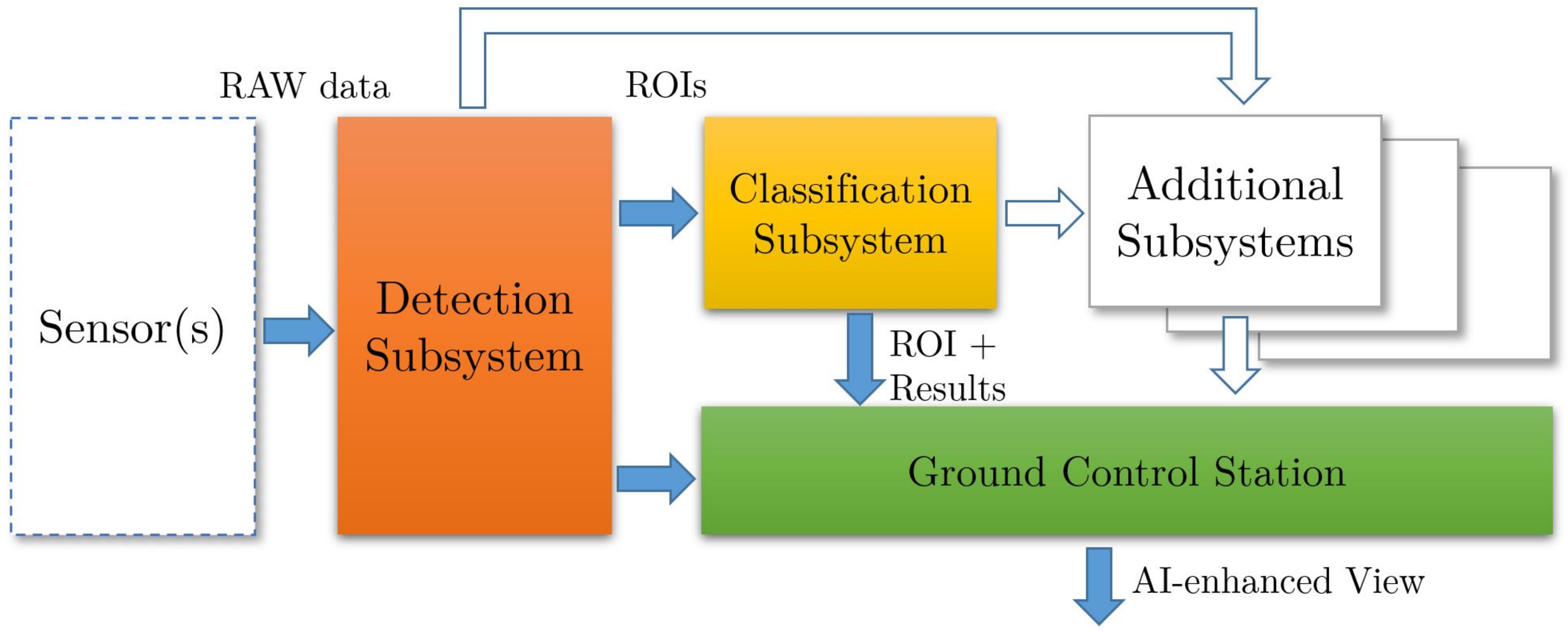
This section details the key architectural elements of the SAA system prototype framework. To illustrate the SAA approach, a prototype architectural framework was designed and developed. Processing is pushed logically close to the sensor to minimize bandwidth latency and wasted computation cycles in an effort to reduce overall power consumption and increase throughput. Furthermore, object Detection and Classification Subsystems are introduced within the data flow pipeline (as in Figure 1) and are designed to perform these operations in parallel, resulting in increased image frame throughput to support real-time operations. The Classification Subsystem utilizes a dispatcher design pattern to perform efficient target classifications in parallel on efficiently-sized full-resolution Regions of Interest (ROI).
An experimental methodology was employed for this research. By first developing an experimental prototype, scenarios and tests with various datasets and classifier models could be subsequently be executed. Repeatability was a key driver in choosing this research methodology as well as the ability to collect real-world results, make observations, perform analysis, and report resultant data.
Generic Commercial-Off-The-Shelf (COTS) hardware was used to rapidly prototype, but further performance and power efficiency gains would likely be possible with more specialized hardware, such as dedicated neural cores and low-power processors.
2.1. Overall Architecture
The overall SAA architecture consists of four major subsystems. Sensor Emulator, Detection, and Classification are three subsystems that reside on-platform; the fourth would remain off-platform, resembling a traditional GCS. As this is a prototype in continued development, wired or wireless Local Area Network (LAN) connections are used to simulate communication between the subsystems. The three on-platform subsystems communicate via a wired Ethernet connection, while communication with the off-platform subsystem is connected via a 2.4 GHz wireless Ethernet link.
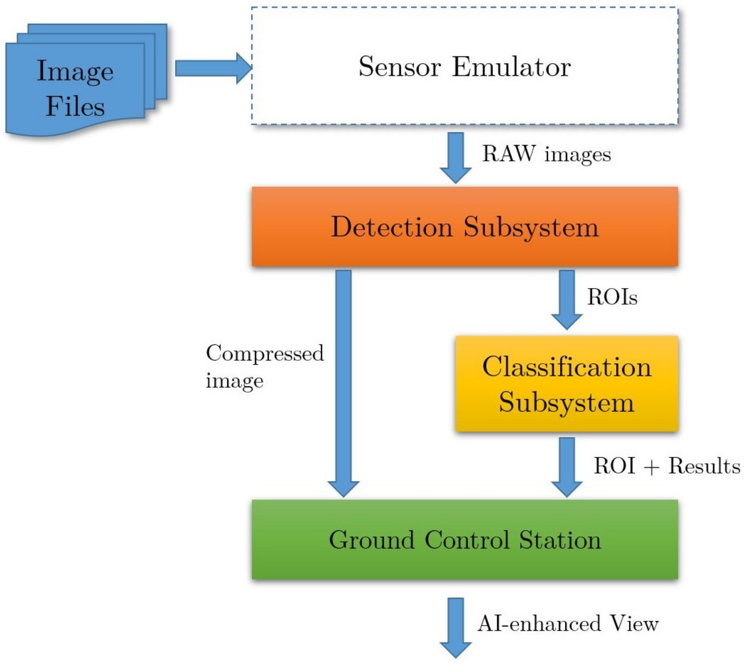
In Figure 2, the overall prototype arrangement and data flow are shown. In lieu of actual sensor hardware, raw image files from a representative sensor are fed from the Sensor Emulator Subsystem into the Detection Subsystem to be processed using conventional image processing and machine vision techniques. Once a ROI is identified and produced to contain a potential target, it is sent to the Classification Subsystem to be processed. Sequentially, it sends a compressed version of the original 4K frame to the GCS for off-platform viewing. Once the Classification Subsystem classifies the object within the ROI using a Deeply-Learned Convolutional Neural Network (CNN), it forwards the ROI with the associated classifier metadata to the GCS via a wireless datalink. The GCS correlates the original frame from the Detection Subsystem with the ROI and classifier metadata from the Classification Subsystem for Artificial Intelligence (AI)-enhanced viewing.
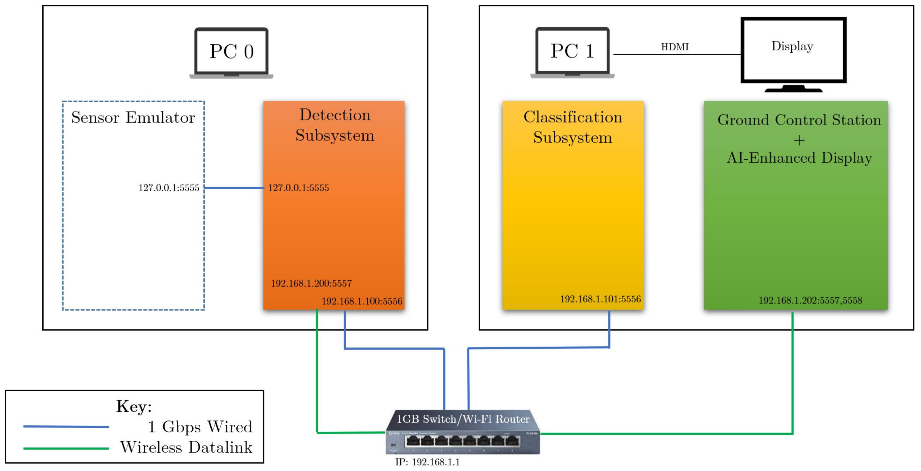
The prototype has been designed and assembled using ordinary COTS hardware. This has enabled rapid prototyping and experimentation at a low cost. Model details of the hardware used are listed in Table 1. These development computers, coupled with a wired/wireless router, serve as the simple prototype hardware. Wired connections simulate inter-subsystem connections present on-platform, while wireless connections are utilized to simulate the datalink to the ground. The network connections of the prototype are detailed in Figure 3.
2.1.1. Sensor Emulator Subsystem
A large data set of 4K images collected from a representative camera is able to be played back through the framework via the sensor emulator. This allows for experimentation with repeatable sequence of frames for simple comparison. These frames are sent to the Detection Subsystem as raw binary data and ingested for detection processing.
2.1.2. Detection Subsystem
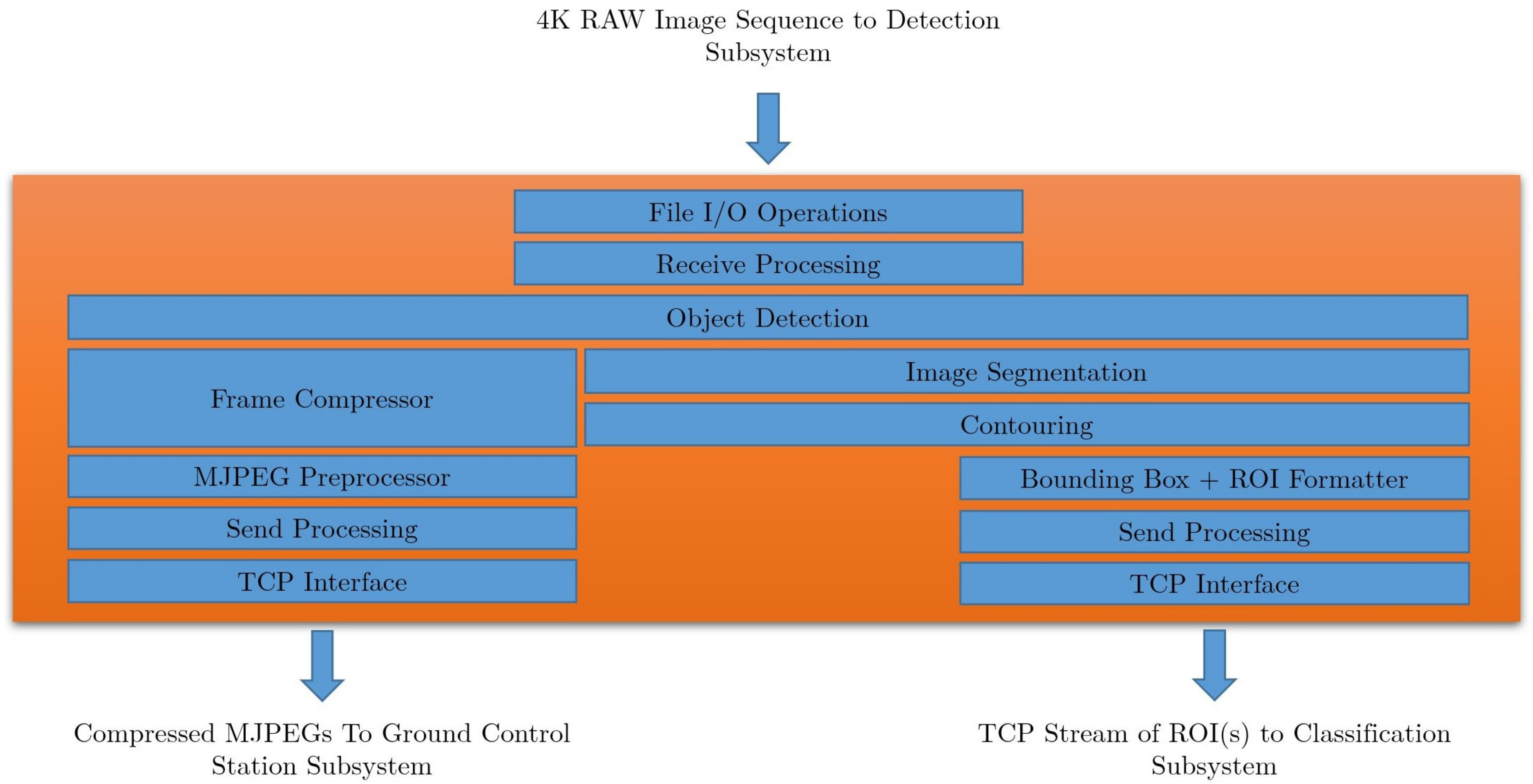
The Detection Subsystem, as shown in Figure 4, utilizes classical computer and machine vision algorithms for object detection. A custom detection algorithm was developed and optimized for clear or gray skies with minimal background clutter. This algorithm performs object detection and segments a small ROI of 20 × 20, 50 × 50, 100 × 100, or 200 × 200 pixels, depending on the target size and distance. This small ROI will be sent to the Classification Subsystem for target classification. When a ROI is identified, the original full image frame is compressed and sent wirelessly to the GCS.
2.1.3. Classification Subsystem
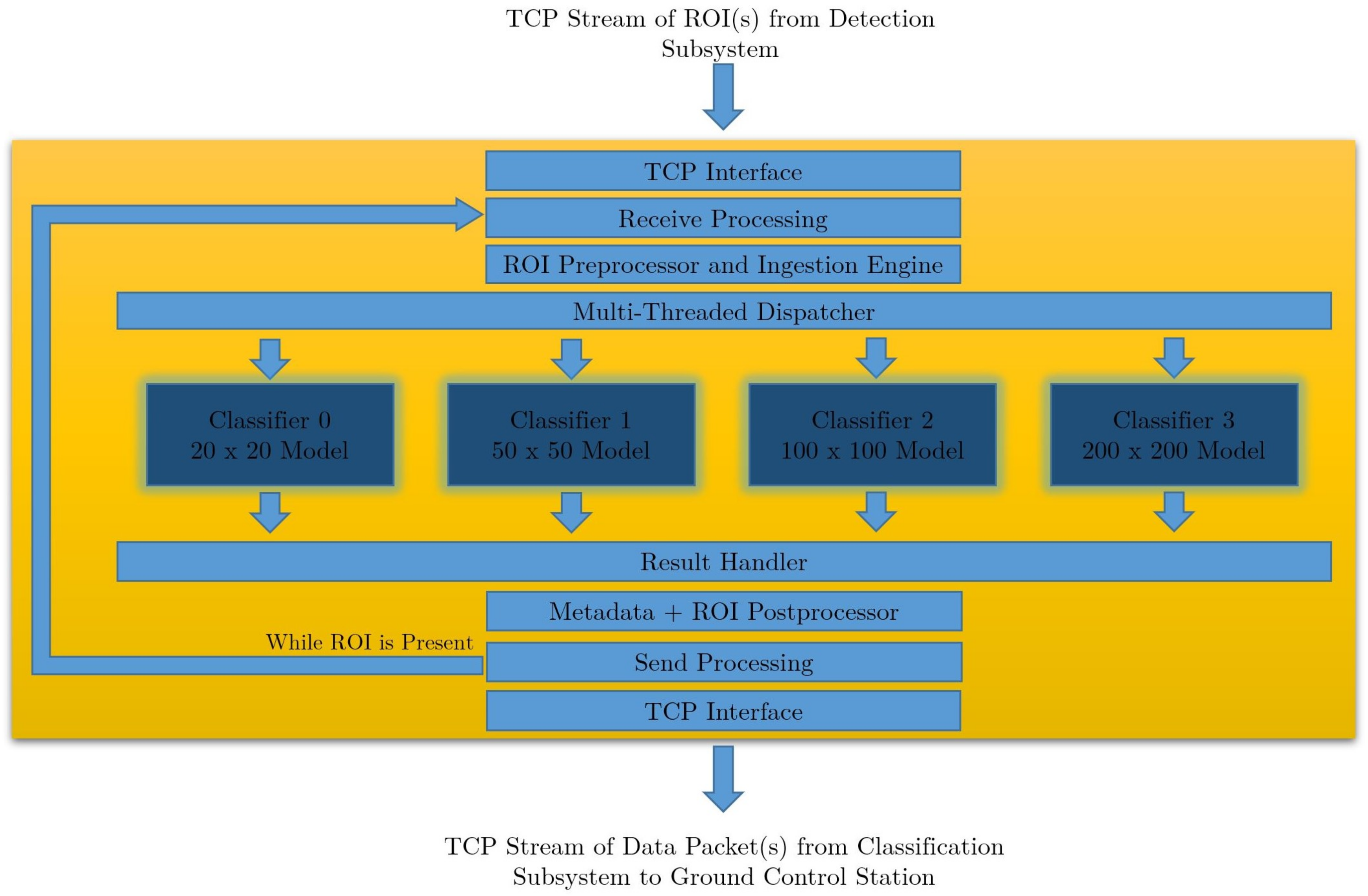
The Classification Subsystem ingests ROIs and uses a multi-threaded dispatcher mechanism to rapidly perform target classification of each received ROI. Target classification is accomplished by performing inference using a Deeply Learned CNN. This network is able to classify the small ROI quickly, accurately, and efficiently by limiting the classifier to a comparatively small area of the original image. This differs from very fast and mature CNNs such as Single Shot Detector (SSD) [18] and You Only Look Once (YOLO) [19], in that the classification portion is further reduced to a single frame and not a sliding frame window. Once an ROI is classified, it is sent to the GCS via a wireless datalink along with its associated inference metadata. These metadata contain the inference probability, classifier label, timestamp, originating camera number, ROI dimensions, and (X, Y) location of the ROI within the original image.
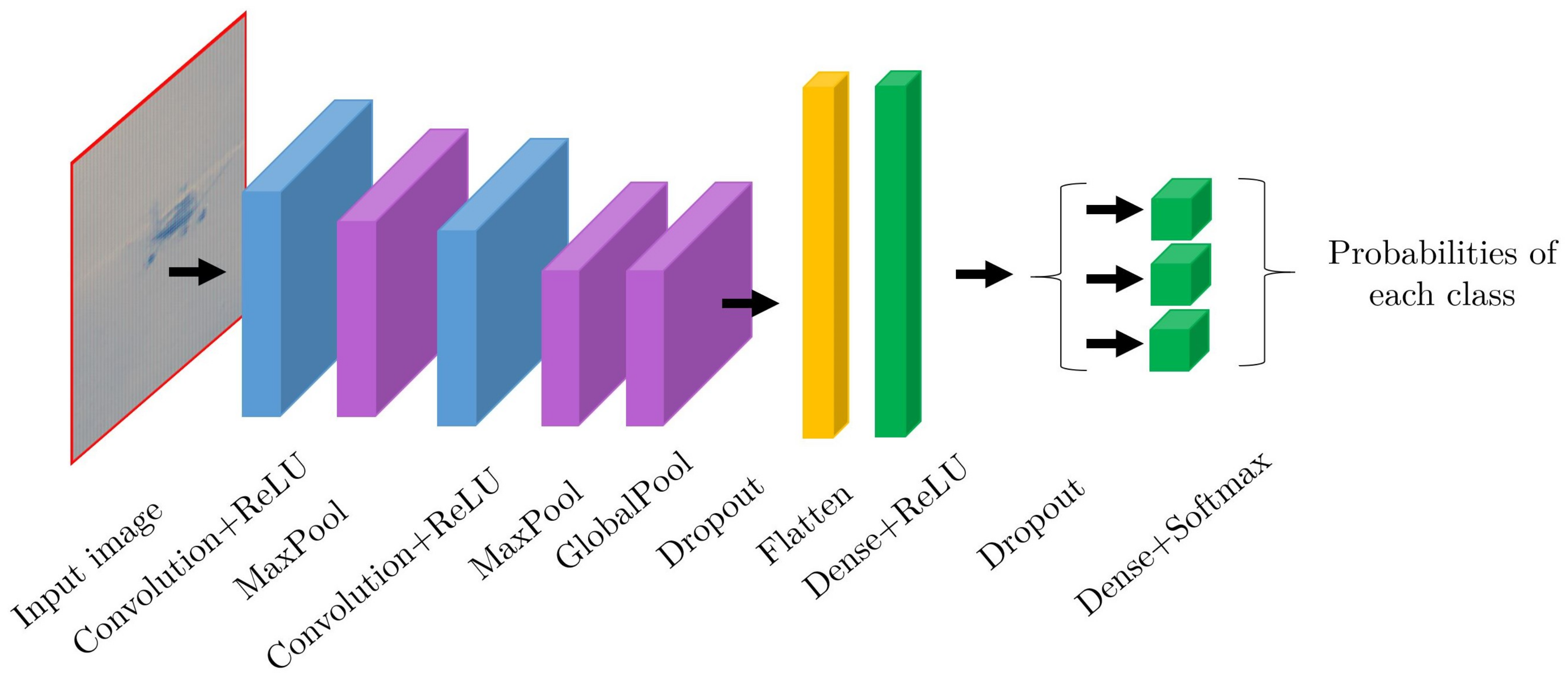
Figure 5 shows the functional decomposition of this Classification Subsystem. The classifiers were trained and validated with a dataset of ROIs from representative cameras. The neural networks were created and optimized using TensorFlow and Keras. Once the desired performance was achieved, the networks were exported as protobuf files (models) for later use within the framework. These models are ingested at runtime for deployed use in the Classification Subsystem. An example structure of how a classifier network might be designed for this construct is shown in Figure 6.
2.1.4. Ground Control Station
The GCS exists in the prototype to serve as an AI-enhanced display. As compressed frames, ROIs, and associated metadata are received at the GCS, and they are correlated using timestamps and spatial coordinates. A high-quality ROI is overlaid on a low-quality, compressed full frame originating at the spatial-temporal coordinates within the video and presented with the classification metadata.
3. Experimental Tests and Discussion
The experimentation was performed using the hardware and network setup described in Figure 3. Figure 2, Figure 4 and Figure 5 show the notional overall sequencing and data flow through each of the subsystems within the prototype framework. Two different deeply learned neural networks were created, trained, and validated to test the edge cases (20 × 20 and 200 × 200) prescribed in the Classification Subsystem architecture. Training and validation data of three different classes was supplied (aircraft, balloon, and bird); therefore, a classification result will consist of three different probabilities mapping to these categories.
Furthermore, presented are baseline results using Microsoft Custom Vision [20] classifier models in Table 2. These models were created by uploading training images and exporting a model to be used within this framework. There is minimal insight into the overall arrangement of the underlying network, but the results serve as a baseline comparison.
4K test imagery of aircraft at varying distances was captured with representative sensors located on the ground aimed towards the departure end of an active runway. Specific test cases were targeted from this data set while collecting processing time and classifier accuracy results.
3.1. Proposed Edge-Centric Two-Stage Adaptive Detection-Classification Approach
As described in the previous section, the Detection Subsystem utilizes a classical OpenCV object detection technique. The Classification Subsystem uses optimized classifiers trained with segmented images to match the intended input ROI size. These subsystems work in concert to enable real-time target classification that can support approximately three frames per second in the framework. Using solely OpenCV object detection methods, without a Classification Subsystem in the data flow pipeline, eliminates the ability to identify a target. Furthermore, a full 4K resolution frame that was determined to contain one or more targets cannot be sent to the Classification Subsystem for processing and maintain real-time capability and accuracy of a smaller, focused classifier. Referring to Table 3, a 4K image processed through the Classification Subsystem took much longer to process. At this delayed processing rate, the architecture could not keep up with the sensor frame injection rate. This also becomes impractical from a power consumption standpoint.
In Table 3, row one shows the result of a full 4K image being downsampled and then inputted into the 200 × 200 model. This takes 1.06 s and has an accuracy of 58%. Conversely, in row two, a 200 × 200 ROI is first produced by the Detection Subsystem and, instead of being downsampled, is then inputted into the 200 × 200 model. The processing time is 0.163 s and achieves an improved accuracy of 77%. This represents about a 19% improvement in accuracy by avoiding the downsampling, while at the same time reduce the processing time from 1.06 s to 0.163 s. An alternative approach is to transmit the entire 4K image off-platform for processing where there are little processing constraints. This approach, however, not only increases data transmission power consumption unnecessarily, but also further increases processing latency.
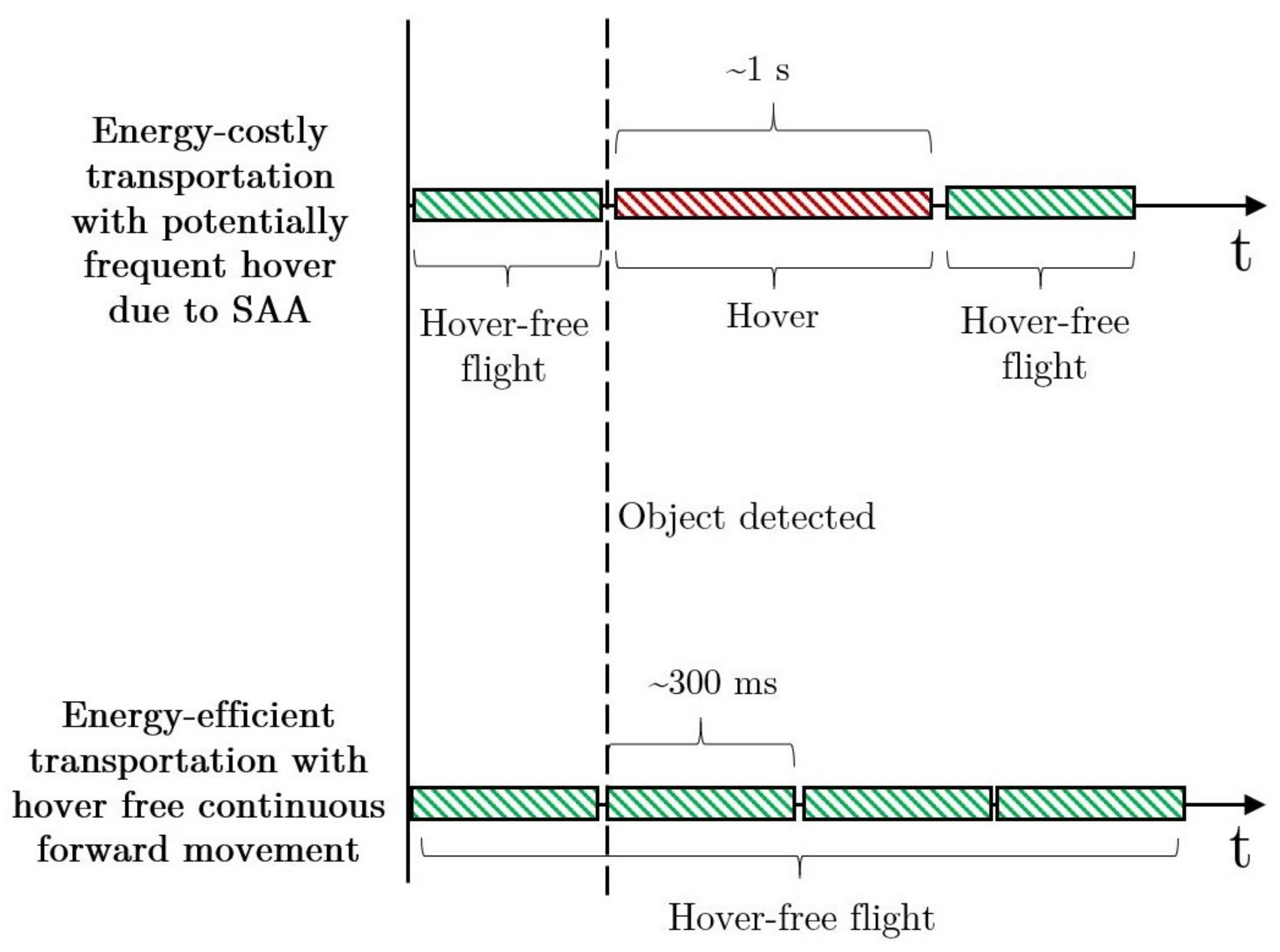
Liu et al. [21] described the typical operating speed for a piston UAV to be between 47 and 52 m/s. Ostler et al. [22] determined, after flight testing a small electric UAV, the typical speed to be around 15 m/s. In a typical operating environment for a UAV, and depending on airspace class, oncoming manned aircraft could be traveling as fast as 250 Knots-Indicated Air Speed (KIAS) or 128 m/s. Ground speeds and closure rates could be even faster accounting for winds aloft. Given these basics speeds, a typical vehicle could travel as much as 128 m, or approximately 420 ft., in a second. One can see these conditions could dictate the sensing UAV might have to stop forward flight to avoid a collision if the hazard is not spotted at sufficient distance, or if processing cannot occur quickly enough. Figure 7 shows the comparison of two operating conditions, with and without sufficient processing, to support continuous forward flight. One second of hover time is used as an approximation of target classification processing time based on the results in Table 3.
Based on the processing time for both approaches in Table 3, a reduction of classification processing time of about 40% was realized when using the Two-Stage Adaptive approach.
Another benefit of this distributed subsystem approach is multiple targets can be detected from a single image frame. Each target will have a ROI segmented and sent to the Classification Subsystem to be processed in parallel. Each ROI will have the original resolution maintained with no compression or downsampling occurring. This retains maximum fidelity and image detail in the ROI provided to the Classifiers, while non-critical portions of the image are compressed for GCS use. Compressing images prior to off-platform transmission reduces power required to transmit large 4K frames.
3.2. Parallel Multi-Size Classifier Approach
In addition to utilizing a Two-Stage, Adaptive, Detection-Classification approach, a dispatched multi-sized classifier is used within the Classification Subsystem. A dispatcher design pattern is used to allow multiple classifiers to be initiated and run in parallel. This allows for multi-target tracking and classification in congested air traffic environments. Using the multi-size approach increases the speed at which target classification can be applied. This method is effective by supplying a small, focused ROI, and not examining the entire 4K frame. This reduces overall classification processing time by a factor of approximately six while still increasing accuracy by roughly 19%, as shown in Table 3. When working in conjunction with the Detection Subsystem, approximately three frames per second can be processed. This is critical for practical applications involving battery powered UAVs. A faster process operating on a small ROI allows for the earliest possible classification and maximum time for avoidance maneuver. This also enables a tailored avoidance maneuver based on the target class and its anticipated flight path. This permits the UAV to have maximum steady-state forward flight and minimizes unnecessary course corrections and the associated power consumption. Using the collected results in Table 3, the optimized 20 × 20 and 200 × 200 models outperform the baseline models in Table 2, in both processing time and accuracy.
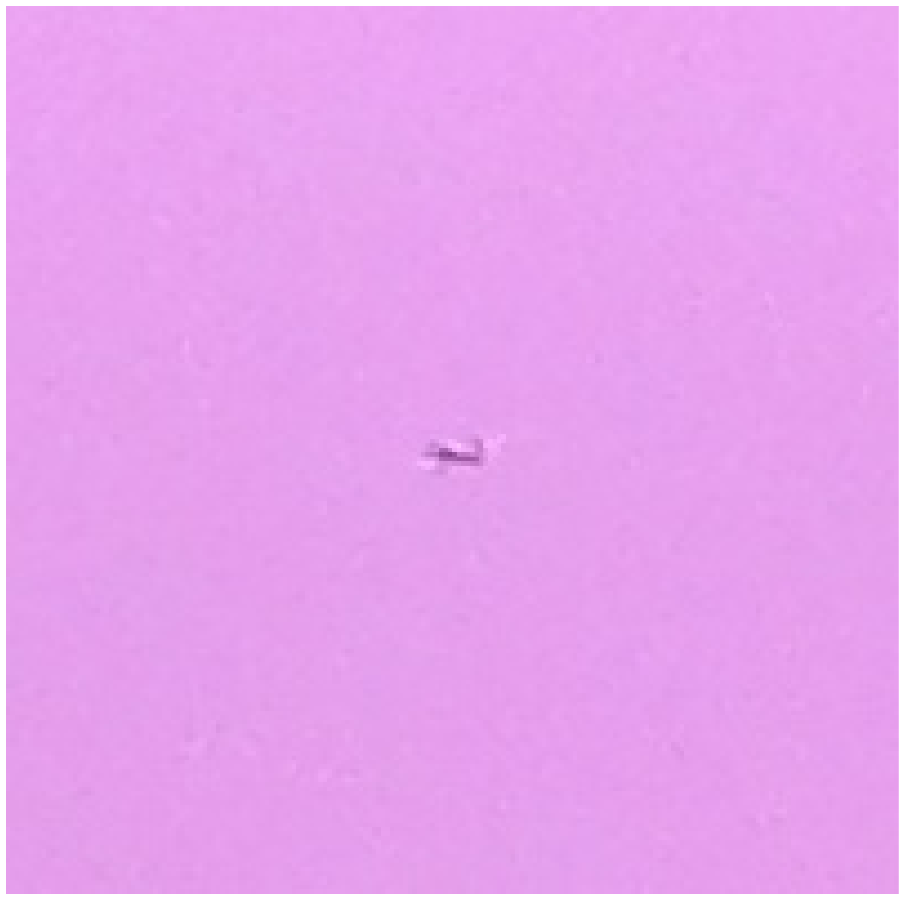
Performing target classification on a very small ROI is feasible on a battery-powered UAV as presented in Figure 7 and Table 3. This approach using small, modular, compact neural networks is a more deployable architecture for small battery-powered UAVs with very limited power. There is minimal processing overhead to classify a small ROI. In the case of both 20 × 20 (e.g., Figure 8) and 200 × 200 (e.g., Figure 9) ROIs, these can be segmented by the Detection Subsystem and processed by the Classification Subsystem to maintain throughput of around three frames per second. Increasing the ROI size from 20 × 20 to 200 × 200 increases average processing time by only less than 20 ms. Using a 4K image directly without the Detection Subsystem is not feasible based on experimental results in the first entry in Table 3. This approach is too slow to keep pace with realistic sensor frame rates and support continuous forward flight.
3.3. Implications on Power Efficiency and Consumption
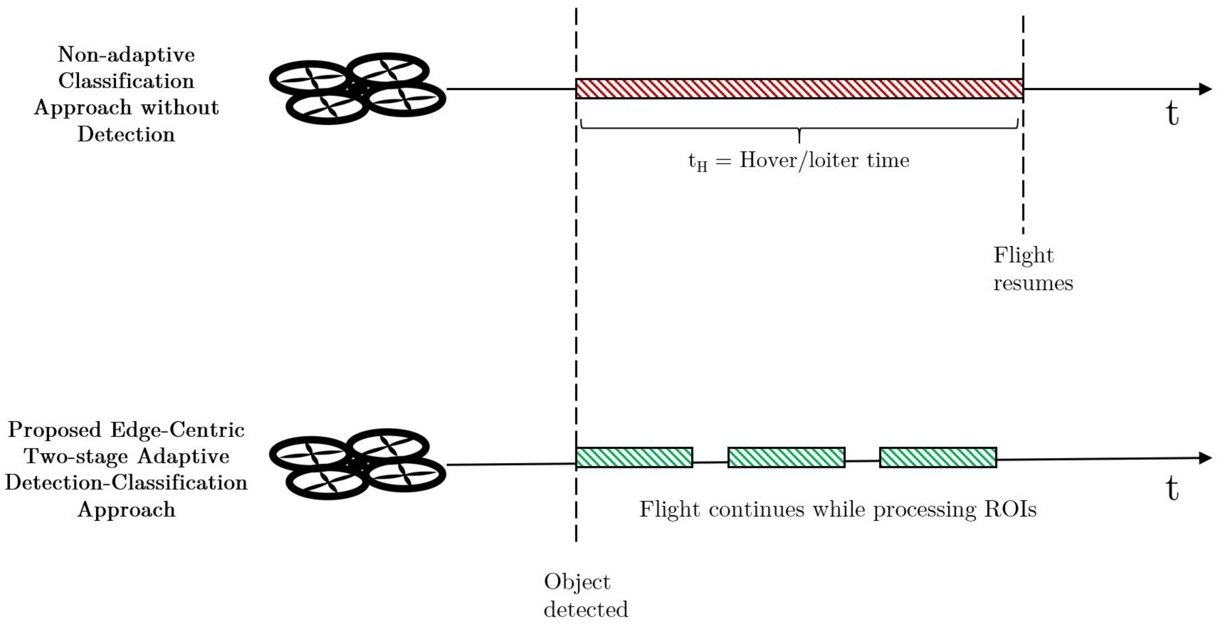
The architecture described here allows for real-time target classification by reducing the processing time to allow for continued flight while processing occurs. To illustrate this fact, consider the two following scenarios presented in Figure 10.
- The first scenario demonstrates a Non-Adaptive Classification Approach without a Detection Subsystem in which a UAV is in forward steady-state flight and the on-board sensor sends a 4K image frame to have target classification applied. This process takes 1.06 seconds according to Table 3. During this processing delay, the UAV must stop forward flight and hover to avoid any catastrophic collisions. Once the target is classified, the UAV can resume forward flight until the next sensor frame is presented for processing.
- The second scenario demonstrates the proposed Edge-Centric, Two-Stage, Adaptive Detection-Classification Approach in which a UAV is in forward steady-state flight and the on-board sensor is sending 4K frames to the Detection Subsystem for processing. Once a target is detected in a frame, a ROI is presented to the Classification Subsystem for target classification processing. According to Table 3, this process takes under 200 ms (actual calculated averages between 141 ms and 163 ms depending on ROI size). While this processing is occurring, the UAV continues forward flight and is not required to stop to hover.
Some assumptions are made to illustrate the approach within a limited scenario to scope and simplify computations:
- Instantaneous acceleration and deceleration. In other words, power consumption is assumed to be equal to steady-state levels during periods of deceleration and acceleration.
- Altitude is five meters.
- No wind or GPS drift requiring course corrections.
- Payload is considered negligible during hover.
- Approximately three frames per second can be processed by the Classification Subsystem and maintain real-time operations.
- UAV-specific flight characteristics and speeds are assumed to match given equations in [23].
- Flight can continue while the Detection Subsystem is processing frames. Based on collected data, it takes 200 ms to process a single 4K frame through the Detection Subsystem.
- Processing power usage is not considered in calculations other than impact on continuous flight. The scope of this paper is focused on power efficiencies due to non-essential hover mitigation, not other energy improvements.
H. V. Abeywickrama et al., have published two insightful works [23,24] developing a comprehensive model for energy consumption of various phases of UAV flight. Notably, these models only account for power consumption of the vehicle in regards to flight dynamics. Power consumption of the physical SAA system is beyond the scope of this paper. Extracting two important equations from their papers leads us to the following:
describes the energy in Joules (J) consumed during hover for a given altitude H in meters for a given time t in seconds.
describes the energy in Joules consumed during steady-state forward flight for a given time t in seconds.
Using Equation (1), the energy consumed during hover in the first scenario is 298.26 J. There would also be additional energy consumption for frame processing and the UAV would not be making forward flight towards completing the task at hand or getting physically closer to its objective. In the second scenario and using Equation (2), this additional 298.26 J would not be consumed, but would rather be limited to forward flight energy consumption of 326.379 J in the same given time period of 1.06 s plus frame processing. If the UAV is required to stop flight to hover or loiter while target classification occurs, it is clear this is untenable and not at all practical for any reasonable frame rate.
4. Conclusions
Current state-of-the-art methods for SAA systems consist of a non-adaptive, single-stage pipeline which are inherently inefficient for battery powered UAVs. This research examined utilizing a novel Adaptive, Two-Stage Detection-Classification architecture for UAV hover mitigation power efficiency gains. Other energy improvements beyond hover mitigation are beyond the scope of this research paper.
An experimental method was utilized to prototype the proposed approach, train lightweight target classifiers, and perform a performance comparison against baseline results. A robust power model was used to approximate UAV power consumption using the proposed SAA architecture against the single-stage SAA.
To summarize, the proposed architecture reduces power consumption and increases efficiency of the SAA system in a three-tiered approach:
- Eliminating hover time while processing frames for target classification.
- Minimizing network downlink transmissions.
- Improving on-platform processing efficiency.
First, the presented approach enables real-time processing of target detection and classification for an on-board image sensor, eliminating the need for the vehicle to stop forward flight and hover during classification processing. Reducing any unnecessary hover reduces wasted energy consumption and maximizes profitable flight time for the UAV. The approach demonstrated here eliminates over 298 J of energy consumption for every frame that is processed.
Second, by pushing target detection and classification to the edge of compute, the need to send vast amounts of imagery to a ground station for processing is eliminated. Overcoming a network-centric UAS architecture improves power consumption by reducing network datalink transmissions.
Third, an Edge-Centric, Two-Stage, Adaptive Detection and Classification Subsystem using classical image processing and deep learning together forms a more efficient method to apply target classification for an entirely on-platform SAA system. Eliminating the Detection Subsystem from the design makes a standalone Classification Subsystem impractical for a SAA system on a battery-powered UAV with real-time requirements. Therefore, it is critical that these subsystems work in concert to perform the SAA function. Utilizing this approach, a 19% improvement in inference accuracy over the baseline classifier models was demonstrated.
While much progress has been made with this approach, there certainly is more work to do. Further refinements to the Classification Subsystem’s CNNs would likely bring new processing and accuracy improvements. Performing a methodical hyperparameter optimization would also be of benefit. The power models used for this initial energy consumption investigation could be fully considered for all phases of flight for a hypothetical mission to gain more insight into the overall power improvements for a typical UAV use case. Additionally, characterizing and adding SAA processor and sensor energy consumption to this already robust power model is desired.
Author Contributions
Conceptualization, N.A.S., C.J.R. and Y.P.; Data curation, N.A.S. and C.J.R.; Funding acquisition, Y.P.; Methodology, N.A.S.; Project administration, Y.P.; Software, N.A.S. and C.J.R.; Supervision, Y.P.; Validation, N.A.S.; Writing—original draft, N.A.S.; Writing—review and editing, Y.P. All authors have read and agreed to the published version of the manuscript.
Funding
This work was accomplished with support from the Ohio Federal Research Network (OFRN)—a program dedicated to building partnerships among innovators in academia, industry and the government to advance science and create jobs in the State of Ohio, under contract number S11161-001.
Institutional Review Board Statement
Not Applicable.
Informed Consent Statement
Not Applicable.
Conflicts of Interest
The authors declare no conflict of interest.
Abbreviations
The following abbreviations are used in this manuscript:
| AI | Artificial Intelligence |
| CNN | Convolutional Neural Network |
| COTS | Commercial-Off-The-Shelf |
| DoD | Department of Defense |
| EASA | European Aircraft Safety Agency |
| FAA | Federal Aviation Administration |
| GCS | Ground Control Station |
| KIAS | Knots-Indicated Air Speed |
| LAN | Local Area Network |
| ReLU | Rectified Linear Unit |
| ROI | Region of Interest |
| SAA | Sense-and-Avoidance |
| SSD | Single Shot Detector |
| SWaP | Size, Power, and Weight |
| UAS | Unmanned Aircraft System |
| UAV | Unmanned Aerial Vehicle |
| YOLO | You Only Look Once |
References
- Hassanalian, M.; Abdelkefi, A. Classifications, applications, and design challenges of drones: A review. Prog. Aerosp. Sci. 2017, 91, 99–131. [Google Scholar] [CrossRef]
- Saeed, A.S.; Younes, A.B.; Cai, C.; Cai, G. A Survey of hybrid Unmanned Aerial Vehicles. Prog. Aerosp. Sci. 2018, 98, 91–105. [Google Scholar] [CrossRef]
- Pfaff, B.L. Overwhelming the SAA System of Delivery UAVs by Drone Swarming. Master’s Thesis, Wright State University, Dayton, OH, USA, 2018. [Google Scholar]
- Rivera, J. Integration of civil unmanned aircraft systems into the national airspace system: Roadmap, plans, and privacy. In Technical Report, Federal Aviation Administration; Department of Transportation: Washington DC, USA, 2014. [Google Scholar]
- US DoD. Unmanned Aircraft Systems Roadmap 2005–Y2030; Technical Report; Department of Defense: Washington, DC, USA, 2005.
- Sesar, J.U. European ATM Master Plan: Roadmap for the safe integration of drones into all classes of airspace. In Technical Report, European Aviation Safety Agency; Publications Office of the European Union: Luxembourg, 2018. [Google Scholar]
- Shakhatreh, H.; Khreishah, A. Optimal Placement of a UAV to Maximize the Lifetime of Wireless Devices. In Proceedings of the 2018 14th International Wireless Communications and Mobile Computing Conference, Limassol, Cyprus, 25–29 June 2018; pp. 1225–1230. [Google Scholar] [CrossRef] [Green Version]
- Zeng, Y.; Zhang, R. Energy-Efficient UAV Communication with Trajectory Optimization. IEEE Trans. Wirel. Commun. 2017, 16, 3747–3760. [Google Scholar] [CrossRef] [Green Version]
- Gramajo, G.; Shankar, P. An Efficient Energy Constraint Based UAV Path Planning for Search and Coverage. Int. J. Aerosp. Eng. 2017, 2017, 8085623. [Google Scholar] [CrossRef]
- Ahmad, Z.; Ullah, F.; Tran, C.; Lee, S. Efficient Energy Flight Path Planning Algorithm Using 3-D Visibility Roadmap for Small Unmanned Aerial Vehicle. Int. J. Aerosp. Eng. 2017, 2017, 2849745. [Google Scholar] [CrossRef] [Green Version]
- Jang, J.S.; Tomlin, C.J. Design and implementation of a low cost hierarchical and modular avionics architecture for the DragonFly UAVs. In AIAA Guidance, Navigation, and Control Conference and Exhibit; American Institute of Aeronautics and Astronautics Inc.: Reston, VA, USA, 2002. [Google Scholar] [CrossRef] [Green Version]
- Fasano, G.; Accado, D.; Moccia, A.; Moroney, D. Sense and avoid for unmanned aircraft systems. IEEE Aerosp. Electron. Syst. Mag. 2016, 31, 82–110. [Google Scholar] [CrossRef]
- Huh, S.; Cho, S.; Jung, Y.; Shim, D.H. Vision-based sense-and-avoid framework for unmanned aerial vehicles. IEEE Trans. Aerosp. Electron. Syst. 2015, 51, 3427–3439. [Google Scholar] [CrossRef]
- Moore, E. Radar Detection, Tracking and Identification for UAV Sense and Avoid Applications. Master’s Thesis, University of Denver, Denver, CO, USA, 2019. [Google Scholar]
- Dennis, A.; Archibald, J.; Edwards, B.; Lee, D.J. On-board vision-based sense-and-avoid for small UAVs. In Proceedings of the AIAA Guidance, Navigation and Control Conference and Exhibit, Honolulu, HI, USA, 18–21 August 2008. [Google Scholar] [CrossRef]
- Al-Kaff, A.; García, F.; Martín, D.; de la Escalera, A.; Armingol, J.M. Obstacle detection and avoidance system based on monocular camera and size expansion algorithm for UAVs. Sensors 2017, 17, 61. [Google Scholar] [CrossRef] [PubMed]
- Lyu, Y.; Pan, Q.; Zhao, C.; Zhu, H.; Tang, T.; Zhang, Y. A vision based sense and avoid system for small unmanned helicopter. In Proceedings of the 2015 International Conference on Unmanned Aircraft Systems, Denver, CO, USA, 9–12 June 2015; pp. 586–592. [Google Scholar] [CrossRef]
- Liu, W.; Anguelov, D.; Erhan, D.; Szegedy, C.; Reed, S.; Fu, C.Y.; Berg, A.C. SSD: Single shot multibox detector. In Proceedings of the 14th European Conference on Computer Vision, Amsterdam, The Netherlands, 11–14 October 2016; pp. 21–37. [Google Scholar] [CrossRef] [Green Version]
- Redmon, J.; Divvala, S.; Girshick, R.; Farhadi, A. You only look once: Unified, real-time object detection. In Technical Report; University of Washington: Washington, DC, USA, 2016. [Google Scholar] [CrossRef] [Green Version]
- Salvaris, M.; Dean, D.; Tok, W.H.; Salvaris, M.; Dean, D.; Tok, W.H. Cognitive Services and Custom Vision. In Deep Learning with Azure; Apress: Berkeley, CA, USA, 2018; pp. 99–128. [Google Scholar] [CrossRef]
- Liu, R.L.; Zhang, Z.J.; Jiao, Y.F.; Yang, C.H.; Zhang, W.J. Study on flight performance of propeller-driven UAV. Int. J. Aerosp. Eng. 2019, 2019, 6282451. [Google Scholar] [CrossRef]
- Ostler, J.N.; Bowman, W.J. Flight testing of small, electric powered unmanned aerial vehicles. Collect. Tech. Pap. 2005, 2005, 484–495. [Google Scholar] [CrossRef] [Green Version]
- Abeywickrama, H.V.; Jayawickrama, B.A.; He, Y.; Dutkiewicz, E. Comprehensive energy consumption model for unmanned aerial vehicles, based on empirical studies of battery performance. IEEE Access 2018, 6, 58383–58394. [Google Scholar] [CrossRef]
- Abeywickrama, H.V.; Jayawickrama, B.A.; He, Y.; Dutkiewicz, E. Empirical Power Consumption Model for UAVs. In Proceedings of the 2018 IEEE 88th Vehicular Technology Conference (VTC-Fall), Chicago, IL, USA, 27–30 August 2018. [Google Scholar] [CrossRef]
Figure 1.
System architecture data pipeline.

Figure 2.
Top-level system diagram.

Figure 3.
Prototype network diagram.

Figure 4.
Detection subsystem block diagram.

Figure 5.
Classification subsystem block diagram.

Figure 6.
Convolutional neural network structure.

Figure 7.
Flight profile comparison.

Figure 8.
20 × 20 region of interest (ROI).

Figure 9.
200 × 200 ROI.

Figure 10.
Flight time scenarios.


Table 1.
Description of commercial hardware.
| Item | Description |
|---|---|
| Laptop (×2) | HP Omen X 17-ap010nr |
| Network Switch/Router | Linksys EA6350 AC1200 |
Table 2.
Baseline Microsoft custom vision models.
| Network Design | Input Image | Detection | Classification | ||||
|---|---|---|---|---|---|---|---|
| Model Dimensions | # of Neurons | Model Size (MB) | Input File Size (MB) | Resolution | Processing Time (s) over 50 run average | Processing Time (s) over 50 run average | Accuracy (aircraft%, balloon%, bird%) |
| 200 × 200 | N/A | 5 | 0.0336 | 200 × 200 | 0.2 | 0.277 | 53, 23, 24 |
| 200 × 200 | N/A | 5 | 39.5 | 4208 × 3120 | N/A | 1.22 | 53, 23, 24 |
Table 3.
Custom deep learning models.
| Network Design | Input Image | Detection | Classification | ||||
|---|---|---|---|---|---|---|---|
| Model Dimensions | # of Neurons | Model Size (MB) | Input File Size (MB) | Resolution | Processing Time (s) over 50 run average | Processing Time (s) over 50 run average | Accuracy (aircraft%, balloon%, bird%) |
| 200 × 200 | 40,551 | 0.355 | 46 | 4208 × 3120 | N/A | 1.06 | 58, 20, 22 |
| 200 × 200 | 40,551 | 0.355 | 0.0336 | 200 × 200 | 0.2 | 0.163 | 77, 11, 12 |
| 20 × 20 | 65,475 | 0.552 | 0.000983 | 20 × 20 | 0.2 | 0.141 | 77, 11, 12 |
Publisher’s Note: MDPI stays neutral with regard to jurisdictional claims in published maps and institutional affiliations. |
© 2021 by the authors. Licensee MDPI, Basel, Switzerland. This article is an open access article distributed under the terms and conditions of the Creative Commons Attribution (CC BY) license (https://creativecommons.org/licenses/by/4.0/).
Share and Cite
MDPI and ACS Style
Speranza, N.A.; Rave, C.J.; Pei, Y. Energy-Efficient On-Platform Target Classification for Electric Air Transportation Systems. Electricity 2021, 2, 110-123. https://0-doi-org.brum.beds.ac.uk/10.3390/electricity2020007
AMA Style
Speranza NA, Rave CJ, Pei Y. Energy-Efficient On-Platform Target Classification for Electric Air Transportation Systems. Electricity. 2021; 2(2):110-123. https://0-doi-org.brum.beds.ac.uk/10.3390/electricity2020007
Chicago/Turabian StyleSperanza, Nicholas A., Christopher J. Rave, and Yong Pei. 2021. "Energy-Efficient On-Platform Target Classification for Electric Air Transportation Systems" Electricity 2, no. 2: 110-123. https://0-doi-org.brum.beds.ac.uk/10.3390/electricity2020007