
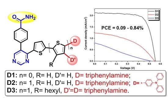
Pyrimidine-Based Push–Pull Systems with a New Anchoring Amide Group for Dye-Sensitized Solar Cells

 , , , , ,
  and
and
Abstract
:
1. Introduction
2. Experimental
3. Results and Discussion
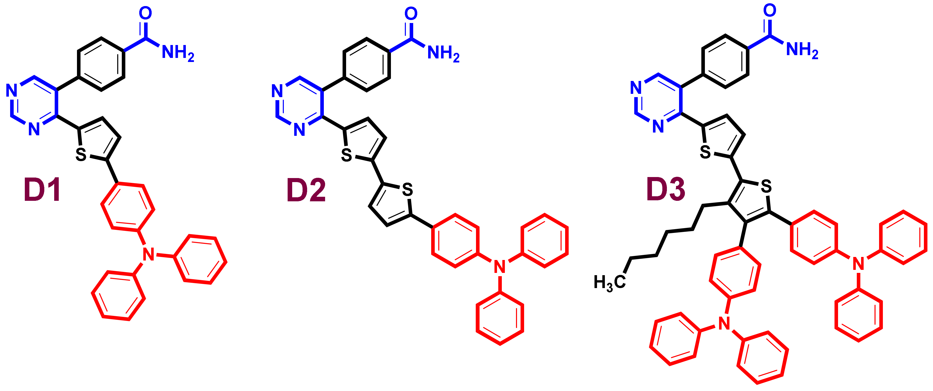
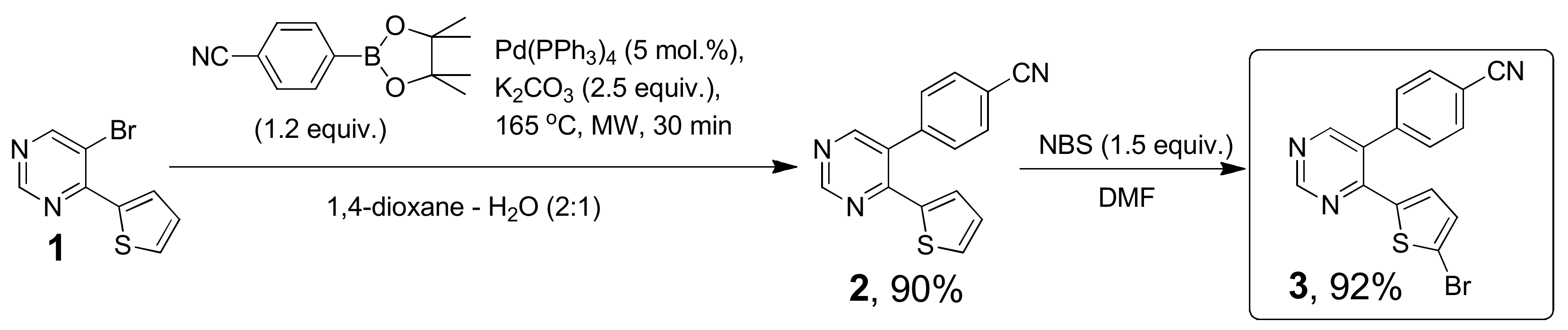
3.1. Synthesis
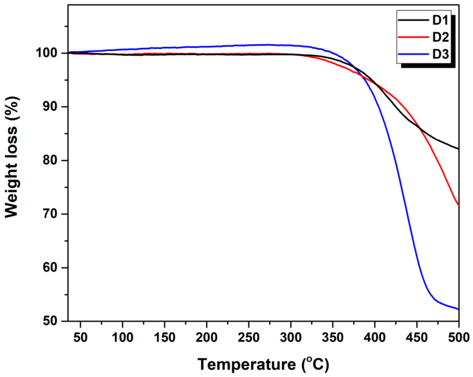
3.2. Thermal Properties
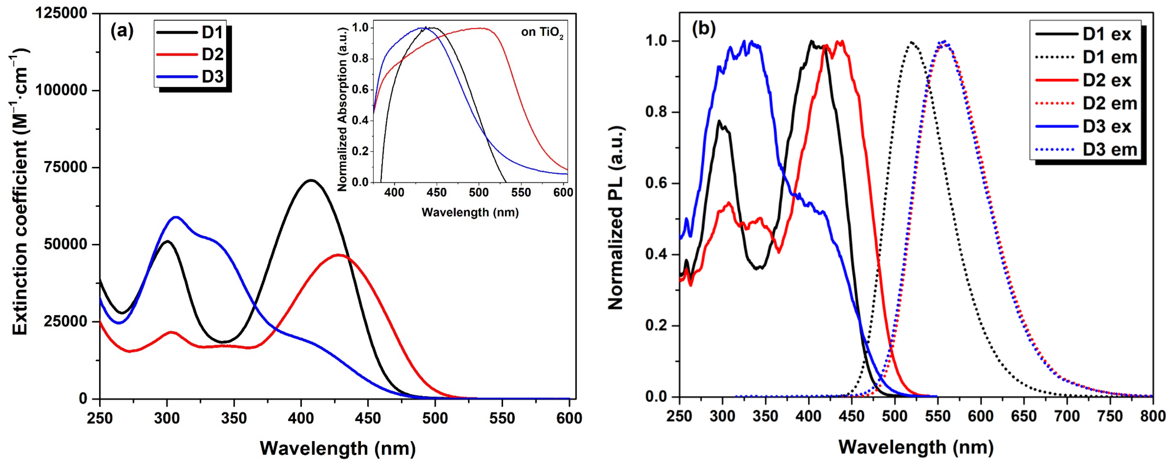
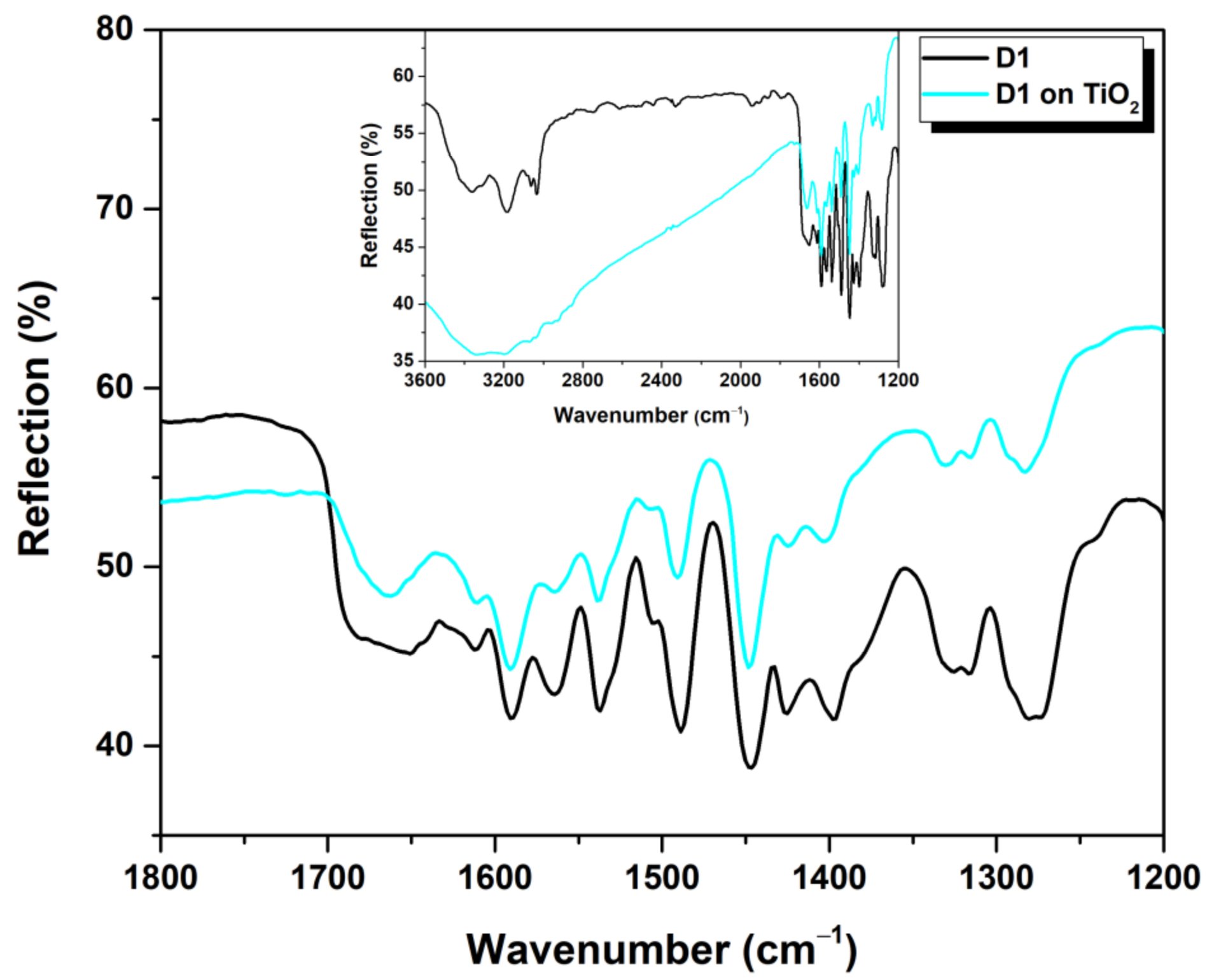
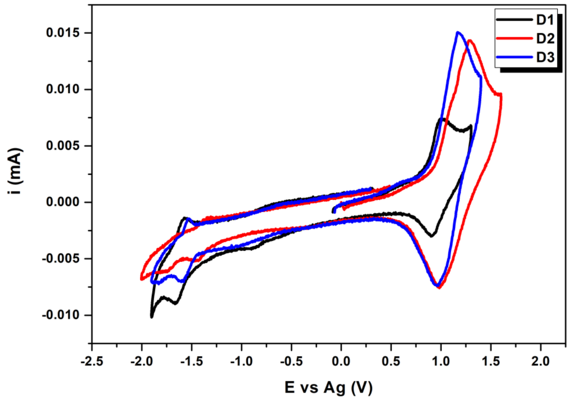
3.3. Photophysical and Electrochemical Properties
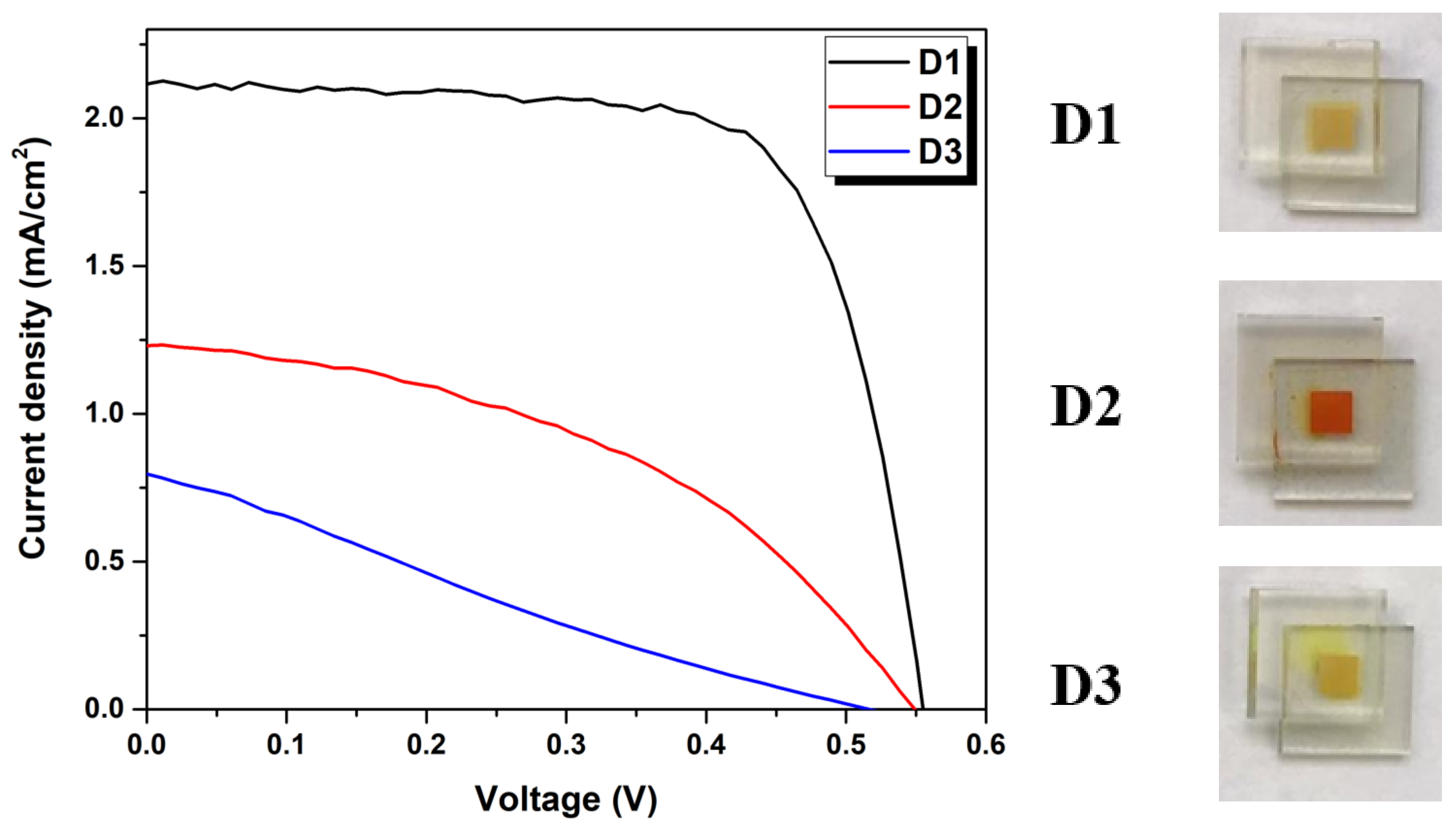
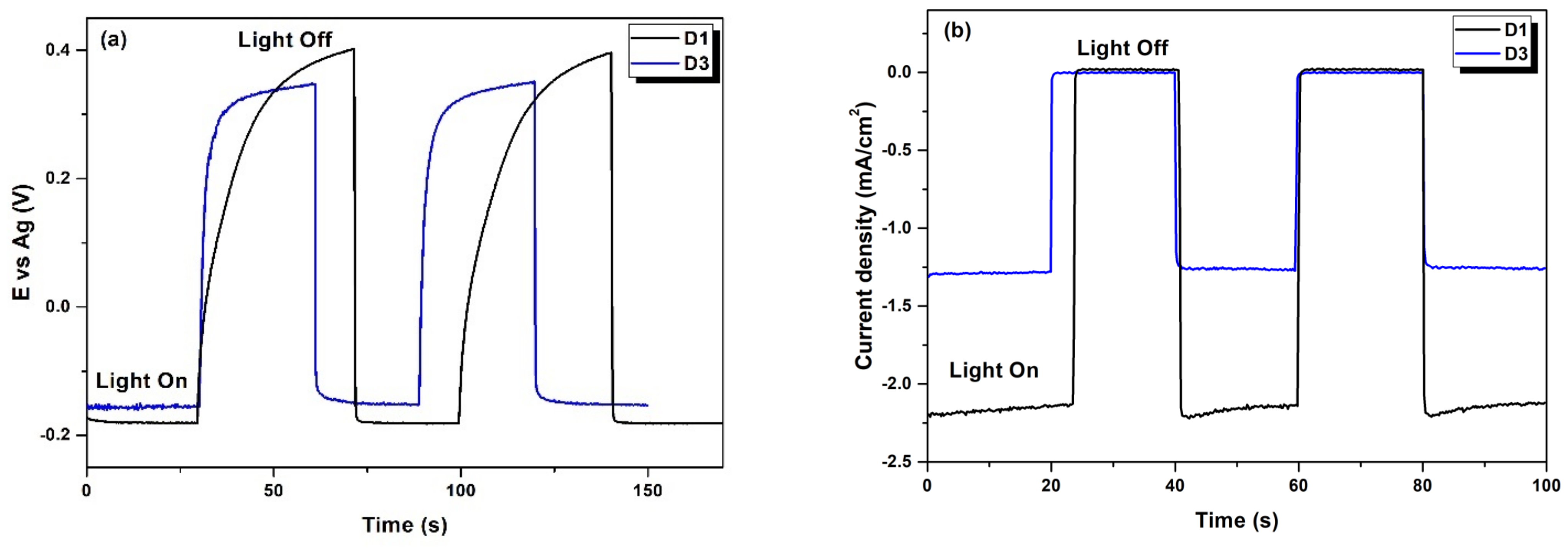
3.4. Photovoltaic Performance of Dyes D1–D3
4. Conclusions
Supplementary Materials
Author Contributions
Funding
Institutional Review Board Statement
Informed Consent Statement
Data Availability Statement
Conflicts of Interest
References
- Hagfeldt, A.; Boschloo, G.; Sun, L.; Kloo, L.; Pettersson, H. Dye-Sensitized Solar Cells. Chem. Rev. 2010, 110, 6595–6663. [Google Scholar] [CrossRef] [PubMed]
- Clifford, J.N.; Martínez-Ferrero, E.; Viterisi, A.; Palomares, E. Sensitizer molecular structure-device efficiency relationship in dye sensitized solar cells. Chem. Soc. Rev. 2011, 40, 1635–1646. [Google Scholar] [CrossRef] [PubMed]
- Urbani, M.; Grätzel, M.; Nazeeruddin, M.K.; Torres, T. Meso-Substituted Porphyrins for Dye-Sensitized Solar Cells. Chem. Rev. 2014, 114, 12330–12396. [Google Scholar] [CrossRef] [PubMed]
- Zhang, L.; Cole, J.M. Anchoring Groups for Dye-Sensitized Solar Cells. ACS Appl. Mater. Interfaces 2015, 7, 3427–3455. [Google Scholar] [CrossRef] [PubMed]
- Ooyama, Y.; Ohshita, J. Development of D-π-A Dye Sensitizers with Azine Ring and Their Photovoltaic Performances of Dye-Sensitized Solar Cells. J. Synth. Org. Chem. Jpn. 2016, 74, 760–780. [Google Scholar] [CrossRef]
- Ooyama, Y.; Uenaka, K.; Ohshita, J. Development of a functionally separated D–π-A fluorescent dye with a pyrazyl group as an electron-accepting group for dye-sensitized solar cells. Org. Chem. Front. 2015, 2, 552–559. [Google Scholar] [CrossRef] [Green Version]
- Ooyama, Y.; Uenaka, K.; Ohshita, J. Synthesis, optical, electrochemical and photovoltaic properties of a D–π–A fluorescent dye with triazine ring as electron-withdrawing anchoring group for dye-sensitized solar cells. RSC Adv. 2015, 5, 21012–21018. [Google Scholar] [CrossRef]
- Verbitskiy, E.V.; Cheprakova, E.M.; Subbotina, J.O.; Schepochkin, A.V.; Slepukhin, P.A.; Rusinov, G.L.; Charushin, V.N.; Chupakhin, O.N.; Makarova, N.I.; Metelitsa, A.V.; et al. Synthesis, spectral and electrochemical properties of pyrimidine-containing dyes as photosensitizers for dye-sensitized solar cells. Dye. Pigment. 2014, 100, 201–214. [Google Scholar] [CrossRef]
- Verbitskiy, E.V.; Schepochkin, A.V.; Makarova, N.I.; Dorogan, I.V.; Metelitsa, A.V.; Minkin, V.I.; Kozyukhin, S.A.; Emets, V.V.; Grindberg, V.A.; Chupakhin, O.N.; et al. Synthesis, Photophysical and Redox Properties of the D–π–A Type Pyrimidine Dyes Bearing the 9-Phenyl-9H-Carbazole Moiety. J. Fluoresc. 2015, 25, 763–775. [Google Scholar] [CrossRef] [PubMed]
- Verbitskiy, E.V.; Cheprakova, E.M.; Baranova, A.A.; Khokhlov, K.O.; Lugovik, K.I.; Rusinov, G.L.; Chupakhin, O.N.; Charushin, V.N. Microwave-assisted synthesis of 4-(2,2′-bithiophen-5-yl)-5-phenylpyrimidine derivatives as sensors for detection of nitroaromatic explosives. Chem. Heterocycl. Compd. 2016, 52, 904–909. [Google Scholar] [CrossRef]
- Ponomarev, E.; Peter, L. A generalized theory of intensity modulated photocurrent spectroscopy (IMPS). J. Electroanal. Chem. 1995, 396, 219–226. [Google Scholar] [CrossRef]
- Kim, D.; Lee, J.K.; Kang, S.O.; Ko, J. Molecular engineering of organic dyes containing N-aryl carbazole moiety for solar cell. Tetrahedron 2007, 63, 1913–1922. [Google Scholar] [CrossRef]
- Rurack, K. Fluorescence Quantum Yields: Methods of Determination and Standards. In Perspectives on Fluorescence; Springer: Berlin/Heidelberg, Germany, 2008; Volume 5, pp. 101–145. [Google Scholar]
- Ooyama, Y.; Inoue, S.; Asada, R.; Ito, G.; Kushimoto, K.; Komaguchi, K.; Imae, I.; Harima, Y. Dye-Sensitized Solar Cells Based on a Novel Fluorescent Dye with a Pyridine Ring and a Pyridinium Dye with the Pyridinium Ring Forming Strong Interactions with Nanocrystalline TiO2 Films. Eur. J. Org. Chem. 2009, 2010, 92–100. [Google Scholar] [CrossRef]
- Zhang, L.; Cole, J.M. Dye aggregation in dye-sensitized solar cells. J. Mater. Chem. A 2017, 5, 19541–19559. [Google Scholar] [CrossRef] [Green Version]
- Saive, R. S-Shaped Current–Voltage Characteristics in Solar Cells: A Review. IEEE J. Photovolt. 2019, 9, 1477–1484. [Google Scholar] [CrossRef] [Green Version]
- Wang, L.; Yang, X.; Li, S.; Cheng, M.; Sun, L. A new type of organic sensitizers with pyridine-N-oxide as the anchoring group for dye-sensitized solar cells. RSC Adv. 2013, 3, 13677–13680. [Google Scholar] [CrossRef]
- Ooyama, Y.; Uenaka, K.; Ohshita, J. Development of D-π-A Fluorescent Dyes with a 3-Pyridyl Group as Electron-Withdrawing Anchoring Group for Dye-Sensitized Solar Cells. Eur. J. Org. Chem. 2015, 2015, 3713–3720. [Google Scholar] [CrossRef]
- Kumar, P.R.; Shajan, X.S.; Mothi, E. Pyridyl/hydroxyphenyl versus carboxyphenyl anchoring moieties in Zn–Thienyl porphyrins for dye sensitized solar cells. Spectrochim. Acta Part A Mol. Biomol. Spectrosc. 2020, 224, 117408. [Google Scholar] [CrossRef] [PubMed]
- Bertoluzzi, L.; Ma, S. On the methods of calculation of the charge collection efficiency of dye sensitized solar cells. Phys. Chem. Chem. Phys. 2013, 15, 4283–4285. [Google Scholar] [CrossRef] [PubMed]


| Dye | Absorption in THF Solution λ (nm)/ε·10−3 (M−1·cm−1) | Absorption on TiO2 λ (nm) | Photoluminescence | E0-0b (eV) | Td c (°C) | ||
|---|---|---|---|---|---|---|---|
| Excitation λmax (nm) | Emission λmax (nm) | ΦFa | |||||
| D1 | 407/71.2 300/51.3 | 446 | 407 300 | 520 | 0.62 | 2.67 | 388.3 |
| D2 | 429/44.9 341/16.8 303/21 | 499 | 429 341 303 | 560 | 0.47 | 2.51 | 393.2 |
| D3 | 400/19.6 306/59.5 | 433 | 400 306 | 558 | 0.14 | 2.62 | 396.5 |
| Compound | EOxonset, V | ERedonset, V | EHOMO, eV | ELUMO, eV | Eg, eV |
|---|---|---|---|---|---|
| D1 | 0.82 | −1.41 | −5.42 | −3.19 | 2.23 |
| D2 | 0.85 | −1.40 | −5.45 | −3.20 | 2.25 |
| D3 | 0.89 | −1.23 | −5.49 | −3.37 | 2.12 |
| Dye | Jsc (mA/cm2) | Voc (V) | FF (%) | PCE (%) |
|---|---|---|---|---|
| D1a | 2.13 ± 0.12 | 0.56 ± 0.01 | 71.85 ± 2.72 | 0.84 ± 0.02 |
| D2a | 1.23 ± 0.01 | 0.55 ± 0.01 | 43.72 ± 4.58 | 0.30 ± 0.03 |
| D3a | 0.78 ± 0.02 | 0.51 ± 0.01 | 23.14 ± 0.63 | 0.09 ± 0.01 |
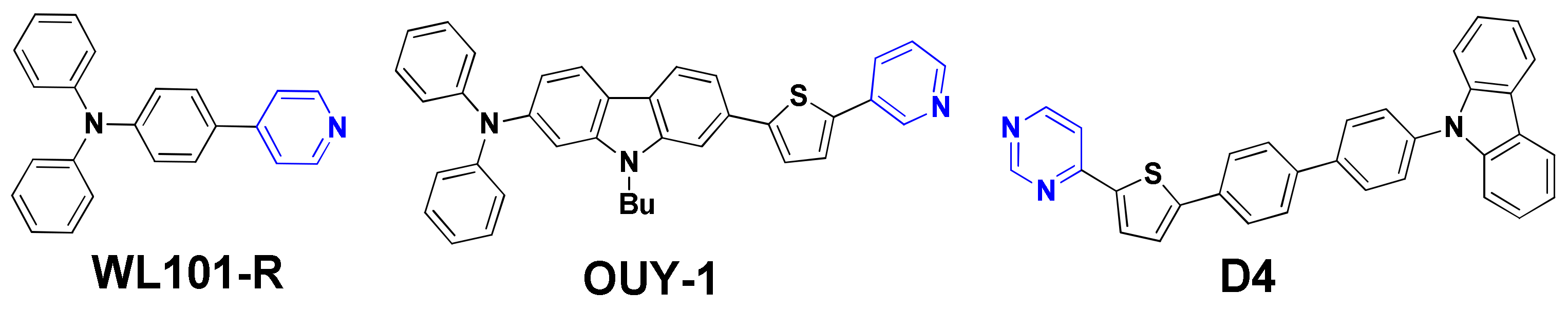
| WL101-Rb | 1.98 | 0.63 | 81.1 | 1.01 |
| OUY-1c | 3.26 | 0.50 | 58.0 | 0.95 |
| D4d | 2.04 | 0.52 | 85.0 | 0.91 |
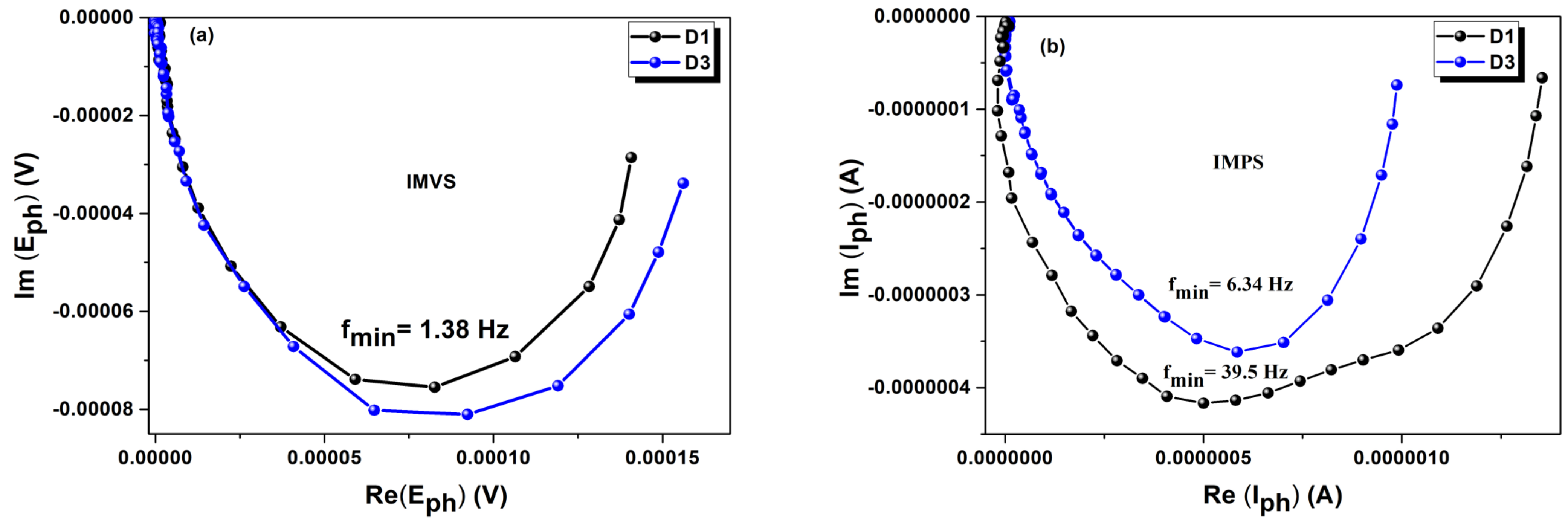
| Dye | ftr, Hz | τtr a, ms | frec, Hz | τrec b, ms | hcc c |
|---|---|---|---|---|---|
| D1 | 39.5 | 4 | 1.38 | 115 | 0.96 |
| D3 | 6.34 | 25 | 1.38 | 115 | 0.78 |
Publisher’s Note: MDPI stays neutral with regard to jurisdictional claims in published maps and institutional affiliations. |
© 2021 by the authors. Licensee MDPI, Basel, Switzerland. This article is an open access article distributed under the terms and conditions of the Creative Commons Attribution (CC BY) license (https://creativecommons.org/licenses/by/4.0/).
Share and Cite
Verbitskiy, E.V.; Steparuk, A.S.; Zhilina, E.F.; Emets, V.V.; Grinberg, V.A.; Krivogina, E.V.; Kozyukhin, S.A.; Belova, E.V.; Lazarenko, P.I.; Rusinov, G.L.; et al. Pyrimidine-Based Push–Pull Systems with a New Anchoring Amide Group for Dye-Sensitized Solar Cells. Electron. Mater. 2021, 2, 142-153. https://0-doi-org.brum.beds.ac.uk/10.3390/electronicmat2020012
Verbitskiy EV, Steparuk AS, Zhilina EF, Emets VV, Grinberg VA, Krivogina EV, Kozyukhin SA, Belova EV, Lazarenko PI, Rusinov GL, et al. Pyrimidine-Based Push–Pull Systems with a New Anchoring Amide Group for Dye-Sensitized Solar Cells. Electronic Materials. 2021; 2(2):142-153. https://0-doi-org.brum.beds.ac.uk/10.3390/electronicmat2020012
Chicago/Turabian StyleVerbitskiy, Egor V., Alexander S. Steparuk, Ekaterina F. Zhilina, Viktor V. Emets, Vitaly A. Grinberg, Ekaterina V. Krivogina, Sergey A. Kozyukhin, Ekaterina V. Belova, Petr I. Lazarenko, Gennady L. Rusinov, and et al. 2021. "Pyrimidine-Based Push–Pull Systems with a New Anchoring Amide Group for Dye-Sensitized Solar Cells" Electronic Materials 2, no. 2: 142-153. https://0-doi-org.brum.beds.ac.uk/10.3390/electronicmat2020012