Article

Latencies in Power Systems: A Database-Based Time-Delay Compensation for Memory Controllers

by
Alexander Molina-Cabrera
1,2,
Mario A. Ríos
1,
Yvon Besanger
3,*,
Nouredine Hadjsaid
3 and
Oscar Danilo Montoya
4,5
1
Department of Electrical and Electronic Engineering, School of Engineering, Universidad de los Andes, Carrera 1 No. 18A-12, Bogotá D.C. 111711, Colombia
2
Department of Electric Power Engineering, Universidad Tecnológica de Pereira, Pereira 660003, Colombia
3
Department of Electrical Power Engineering, Universite Grenoble Alpes, CNRS, Grenoble INP, G2Elab, 21 Avenue des Martyrs, 38000 Grenoble, France
4
Facultad de Ingeniería, Universidad Distrital Francisco José de Caldas, Bogotá D.C. 11021, Colombia
5
Laboratorio Inteligente de Energía, Universidad Tecnológica de Bolívar, Cartagena 131001, Colombia
*
Author to whom correspondence should be addressed.
Submission received: 27 November 2020 / Revised: 13 January 2021 / Accepted: 13 January 2021 / Published: 18 January 2021
(This article belongs to the Special Issue Grid-Connected Renewable Energy Sources)

Abstract

:
Time-delay is inherent to communications schemes in power systems, and in a closed loop strategy the presence of latencies increases inter-area oscillations and security problems in tie-lines. Recently, Wide Area Measurement Systems (WAMS) have been introduced to improve observability and overcome slow-rate communications from traditional Supervisory Control and Data Acquisition (SCADA). However, there is a need for tackling time-delays in control strategies based in WAMS. For this purpose, this paper proposes an Enhanced Time Delay Compensator (ETDC) approach which manages varying time delays introducing the perspective of network latency instead dead time; also, ETDC takes advantage of real signals and measurements transmission procedure in WAMS building a closed-loop memory control for power systems. The strength of the proposal was tested satisfactorily in a widely studied benchmark model in which inter-area oscillations were excited properly.

1. Introduction

Wide Area Measurement Systems (WAMS) bring information to the control center in modern power systems to improve observability for achieving stability and security [1,2]. WAMS are integrated by Phasor Measurement Units (PMU) and a sophisticated communication infrastructure [3,4,5,6,7]. This communication infrastructure is based on several standards, interoperability of devices, language, and agents involved in the procedure. Also, this infrastructure involves protocols such as TCP/IP and UDP/IP to provide redundancy, guarantee information integrity, solve traffic problems, and tackle failures of some links [8,9,10,11]. For observability purposes, WAMS is better than traditional supervisory control and data acquisition (SCADA). Unfortunately, the measurements managed by WAMS reach the control center with time-delay due to the size of large power systems monitored as well as procedures such as filtering, digitalization, time stamping, and labeling [8,12]. The time-delay is problematic in closed loop control for power systems; i.e., time-lapse in the backward channel is an important issue that emerges with undesirable effects on the performance of transferred power due to inter-area oscillations and frequency oscillations, among others [13,14,15,16,17].
There are many authors who are committed to tackling the time-delay problem in power systems, but the main problem remains unsolved. In the most common perspective, the time compensators were used considering time-lapse as a dead-time phenomenon. In this direction, one of the first time-delay strategies for compensation was the Smith Predictor (SP), primarily used in chemical process [18,19,20]. In [19], Chaudhuri et al. implemented a unified SP to design a damping control, but its success dependeds strongly on the exactitude of the model. Then, they proposed a unified Smith phasorial time-delay compensator which runs fast with few calculations; nonetheless, it only works well for small values of delay [21]. Moktari developed a time compensator based on fuzzy logic, which works well for higher values of time delays close to tens of milliseconds; however, it fails in cases of disturbances associated with tripping lines [22]. Another more sophisticated perspective considers the complexities of actual WAMS. For instance, [23] obtains time-delay values from isolated arriving signals using time-stamp from the data package. The authors of [10] employ the knowledge of the WAMS only to simulate the communication procedure in a Hardware In the Loop (HIL) test but leave these data out of the compensation strategy. The first perspective presented above fails because it considers time-delays as a dead-time phenomenon, as in a chemical process; in the second perspective, the complexity of WAMS is considered, but no capitalization of the valuable information available from the communication process is carried out. Generally, recent investigations suffer from misconceptions in modeling and simulating scenarios of time-delay performance [24,25,26]. Following with the literature revision, the authors in [27] obtain worthy results using buffers and a wide-area power oscillation damper (WPOD) to compensate for delays and packet dropouts; nevertheless, the implementation is based on a straightforward model for single-input single-output applied in a Double-Fed Induction Generator (DFIG). Another drawback in the proposal: it takes a long time to stabilize signals (more than 20 seconds) with dangerous power explorations (more than one hundred percent and negative values). Consequently, the main gap in the literature to be filled is the absence of a definitive proposal to face power system oscillations increased by time-delays, considering a more realistic performance of WAMS with high values for network latencies [10,28,29,30,31].
There are previous contributions to the aforementioned gap: our early works include an adapted Model Predictive Control (MPC) capable of dealing with the nonlinear large-scale nature of delayed power system (power systems with delays in WAMS) to maintain stability; then, we introduced time-delay compensation suitable for tackling fixed and varying values of latencies [32,33,34]. This paper contributes in time compensation strategies for reaching a memory closed loop control in delayed power systems; furthermore, this work details the WAMS’ performance to offer the background needed for the proposal (to run more realistic simulations). The strategy is named Enhanced Time-Delay Compensation (ETDC): it features a Kalman-based time-compensator and a time-organized database of measurements. The ETDC introduces the concept of the Most Updated Available (MUA) information, which is the key value to feed the MPC. The inclusion of historic data in the control closed loop leads to a memory controller to face latencies.
The paper is organized as follows: Section 2 summarizes the general problem of latencies in communications, including some details of their behavior, typical values, and shape. Subsequently, a typical performance of time-delays is illustrated, which will be considered for simulations. Section 3 describes the model of power systems with delays in the backward channel to offer a better picture of the control problem from a math perspective, thereby allowing us to hypothesize the possible solution. Then, in Section 3.2, the Enhanced Time-Delay Compensation is introduced, and some statements are made to study the convenience of the solution. Finally, the results of the simulation (Section 4), conclusions, and further works (Section 5) are presented.

2. Latencies in Wams Communications Infrastructure: Reaching a More Realistic Model

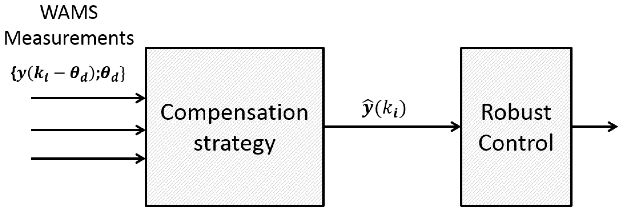
2.1. The General Delayed Communication Infrastructure

At present, energy management systems (EMS) have been improved with the introduction of Phasor Measurement Units (PMUs) and their supporting infrastructure. PMUs are fundamental elements of the modern Wide Area Measurement Systems (WAMS), whose capabilities allow the development of Wide Area Monitoring and Control Systems (WAMCS) [3,34,35,36].
Secondly, signals from several PMUs installed in different locations are gathered with Phasor Data Concentrators (PDCs) to run an additional routine of synchronization; then, each PDC sends the new data packet to the super PDC (SPDC) or directly to the control center. However, these signals do not arrive at the same time due to the inherent latency of communication channels. For this reason, before running the synchronization, PDC manages the absence of simultaneity of the arrival of signals with the assistance of either TCP/IP or UDC/IP protocol. Despite this compensatory mechanism, the total latency increases [8,9].
The measurements are taken with electrical sensors in substations and main buses; then, they are synchronized with PMUs and sent to the control center. The resulting information packet complies with C.37.117.7 and IEC 61850 standards [37]. This procedure includes not only metering but also filtering, processing, digitalization, and time-stamp labelling. Obviously, this procedure add delays to the signal and it is considered the first component of the latency in WAMS.
In cases of a wide area power system, the utilities gather the information of PMUs and other regional PDCs through a Super PDC (SPDCs). Then the SPDCs send the signals to the control center. The time spent by the SPDCs in this process increases the time-delay [8,9,38]. Finally, at the control center, all the signals are gathered to allow control in Wide Area Monitoring Protection and Control (WAMPaC) [6,9].
Another important component of latencies is the signal flying time to travel through the medium and routers at each link. Their stochastic behaviour contributes to the total time delay [35].
In addition to the aforementioned physical infrastructure, the TCP/IP protocol, as well as C.37.117.7 and IEC 61850 standards, are introduced in power system communications to provide flexible, reliable, and standardized communications [8,37]. Standards C.37.117.7 and IEC 61850 provide values of satellite-synchronized time-stamp for each measurement in the WAMS. This time stamp is valuable in the proposal because it allows to determine each signal latency value, which is subsequently included in the compensation scheme. Now, the TCP/IP protocol is responsible for the information interchange among the agents in the communication network. Based on the protocol, the sender always guarantees the reception of the data packets in the final destination. Despite this guaranteed reception, some authors have focused their efforts on the need to face a non-existent loss of data packets [39].
The aforementioned WAMS description shows the capabilities of the power systems’ communication infrastructure. In WAMS, the well-structured packets transferred with TCP/IP should be organized in databases due to their useful information (e.g., time stamps), with the purpose of improving power system control and time compensators.

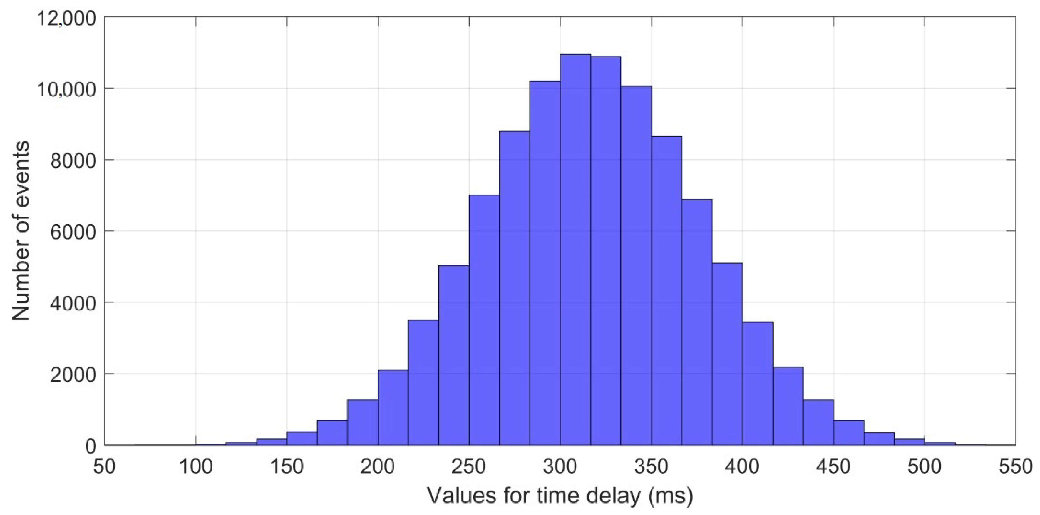
2.2. Behavior and Modeling of the Random Time Delays in the Pmu Communication Infrastructure

The communication infrastructure can be understood as a net of devices interconnected through communication links. They collect and process information in some topological nodes. Two major delay components are considered to describe the latency. Firstly, τ v denotes the total time delay produced by the devices mentioned in the previous section (PMU, PDC, SPDC). Secondly, τ link is the total additional latency due to the links of the communication process; τ link is related to the weather conditions and the medium and is generally greater than τ v [35]. The sum of these values is given by:
τ d = τ v + τ link ,
Table 1 shows the typical corresponding ranges of τ d for different communication links in power systems.
The development of tools to deal with delayed systems requires clarity of the network latencies. The time-delay is stochastic and unpredictable; however, it is possible to model time delays with a probability density function as in [8]. The authors in [8] gathered empirical data, and then they made a goodness-of-fit test. They found that Gaussian shape properly models the time delay behavior of τ d with a formal math representation given by:
τ d = N μ G , σ G ,
The advantages of the τ d representation in (2) are a better description of the varying time-delay and the possibility of running more realistic simulations. Figure 1 illustrates an example: the histogram of events called D G with a mean value μ G = 300 ms and standard deviation σ G = 60 ms. The maximum value for the time delay in this set is close to 550 ms. Typical values μ G and σ G presented in [8,40] were adapted for this research to include the effects of the latencies in the simulation of the power systems’ behavior.

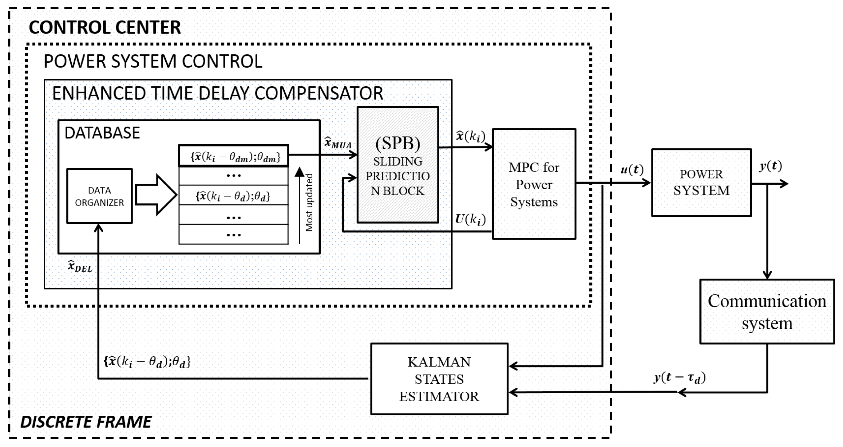
3. The Enhanced Time-Delay Compensator for Time-Delayed Power Systems Control: Modeling the Problem to Propose a Solution

In this section, we derive the math model of the closed loop considering the power system with its nonlinearities because the proposed control must act over the actual nonlinear power system. The math model includes the behavior of network latencies in the feedback channel and the control law based on the estimated delayed states. Based on this model, it was possible to determine the complexities involved in the whole problem to hypothesize a solution. Then, in Section 3.2, the structure of the ETDC is described, taking into consideration the WAMS’ description in Section 2 and the math model in Section 3.1. Following this, ETDC consistency and stability are studied trough some statements at the end of Section 3.2.

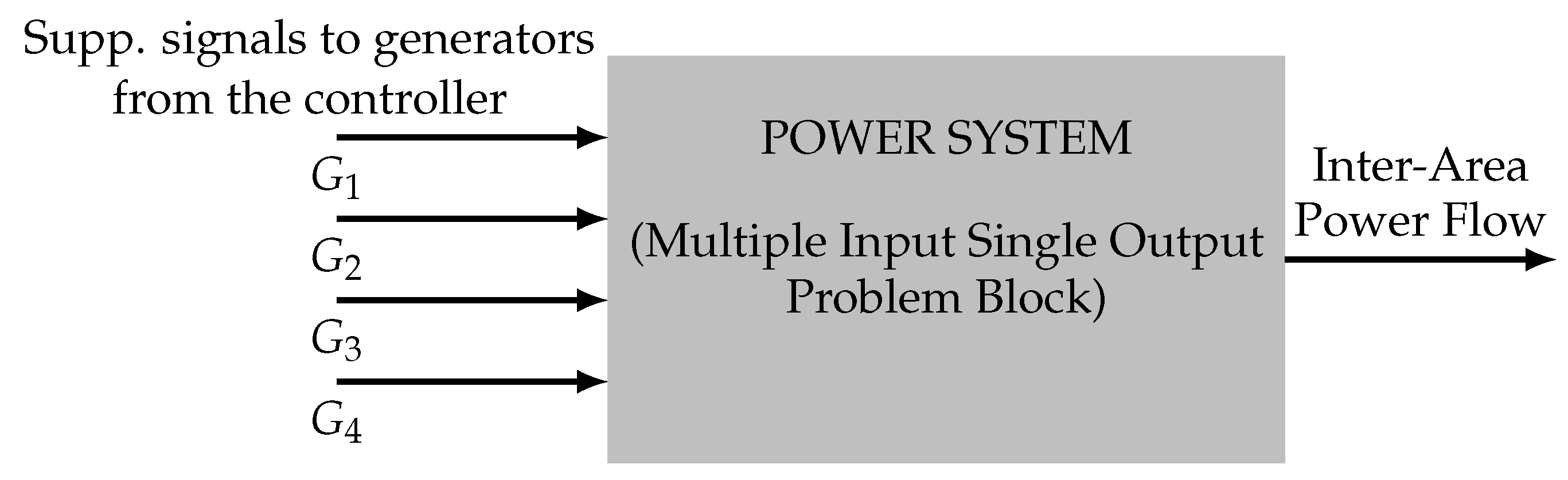
3.1. Time-Delayed Power Systems Modeling

The present paper proposes a formal model to include the nonlinearities of power systems and the variability of time-delays, which is made with the purpose to provide a more appropriate representation of the WAMS communications infrastructure. The formulation for modeling the dynamic behavior of nonlinear power systems is as described by (3)–(7):
x ˙ t = f x ( t ) , u ( t ) ,
In this case, u ( t ) denotes the feedback control law. Basically, Equation (3) describes a memoryless closed loop strategy and if the control law is u ( t ) = γ ( x ( t ) ) , then it turns into:
x ˙ t = f x ( t ) , γ ( x ( t ) ) ,
Equation (4) represents the ideal case with a proper control law and accessibility to actualized states. Hence, considering the latency in communications in the feedback channel affecting u ( t ) , the nonlinear problem formulation turns into the autonomous model:
x ˙ ( t ) = x ( t ) , γ x t τ d ,
Now, by including the expression for τ d denoted by (2):
x ˙ ( t ) = x ( t ) , γ x t N μ G , σ G ,
Equation (6) gathers two emerging difficulties to be tackled in real applications on power systems. The first is the power system’s nonlinear nature (including parameter-changing, uncertainties and its large number of variables); the second is associated with time delays in the closed loop control strategy. In this regard, although the nonlinearity was successfully addressed in [32,33], the dead time misconception is yet to be faced.
Finally, the computation of the control law in Equation (4) requires the values of x ( t ) . The typical way to obtain the states in such a complex system is by using state estimators like Kalman filters. Basically, estimators derive estimated values of states, x ^ ( t ) , from output signals y ( t ) . Hence, Equation (6) turns into:
x ˙ ( t ) = x ( t ) , γ x ^ t N μ G , σ G ,
Note the following: Equation (7) establishes the complexity of the problem, which is highly nonlinear, and the controller must use estimated states x ^ ( t ) instead of actual states x ( t ) . In addition, it is included the stochastic behaviour of the time-delay trough N ( . ) . From this point, a valuable strategy must keep values of (7) as close as possible from (4) to achieve a good performance.

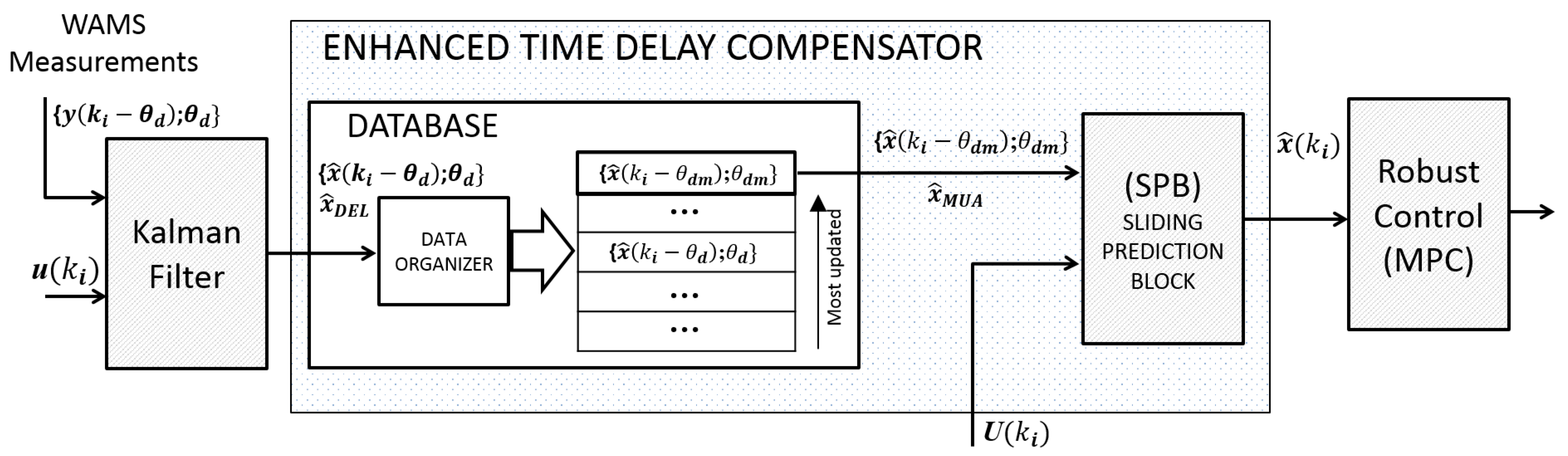
3.2. The Enhanced Time-Delay Compensator

This section shows an improved time compensator named Enhanced Time-Delay Compensator (ETDC), which is more suitable for practical power systems and represents a major improvement when compared to previous research in two main aspects: (a) it manages varying values of latencies under a new paradigm that re-evaluates the dead time misconception and (b) incorporates real WAMS operational elements.
As mentioned in the introduction, time-delay compensation is a strategy included in the closed loop controllers to obtain actualized states for the feedback control law in which signals reach the controller with a retard [18,19,20,41,42]. The main objective of a time compensator is to reduce the error e ( t i ) = x ^ ( t i ) x ( t i ) at a given time t i , where x ^ ( t i ) is calculated by the time compensator and x ( t i ) represents the actual and unknown states. In the compensation strategy, the vector x ^ ( t i ) is calculated from the delayed values x ( t i τ d ) [18,19,20]. Most compensators work satisfactorily under two main conditions: the precise model of the system and the knowledge of the constant time-delay value. However, it is almost impossible to have an exact model of the system. Consequently, the implementation of those compensators in real systems has been thwarted: instabilities emerge even with small errors in the model [18,41,43]. The challenge at this regard is identifying how to compensate delayed signals without adding instabilities: here ETDC plays an important role. In Figure 2, the traditional scheme of compensations is illustrated.
The proposed ETDC is composed by two main components to be presented: the Sliding Prediction Block, and the added database. By this way, in the closed loop control the ETDC compensates the network latencies; next, signals are delivered to the control strategy. Then, control signals are sent to the power system.
The first component of the ETDC is the Sliding Prediction Block. The authors have been developing tools for damping oscillations in power systems with delays in their communication [33]. As a previous contribution, a time-delay compensator called Sliding Prediction Block (SPB) has been developed. It performs properly with the Model Predictive Control (MPC) strategy adapted to power systems. The SPB is as follows: the classic Kalman filter is fed by the couple y ( t i ) u ( t i ) to obtain x ^ ( t i ) . The novelty here is: SPB is fed by the delayed states x ^ ( t i τ d ) and the known historical control sequence U ( t i ) = [ u ( t i τ d ) u ( t i τ m ) u ( t i ) ] . The values of x ^ ( t i τ d ) are obtained by a previous Kalman filter fed by y ( t i τ d ) u ( t i τ d ) . Another Kalman filter stage is used recursively to obtain x ^ ( t i ) from x ^ ( t i τ d ) . Then, the states are brought to the control strategy.
The second main component of the ETDC is the database which allows keep old measurements. Discrete time is considered for the description. The database takes arriving signals x ^ ( k i θ d ) ; θ d and lists them according to the value of the time delay (here, θ d is the corresponding time-delay for the delayed signal x ^ ( k i θ d ) ). The less-delayed data packet is allocated at the top of the list and denoted by x ^ ( k i θ d m ) ; θ d m . This packet will become the Most Updated Available state, x ^ MUA , and it allows the building of a memory control strategy for delayed power systems. Then, x ^ MUA is delivered to the SPB for the time-compensation. The listing procedure is possible owing to the processing of signals during PMU measurements in compliance with IEEE C37.118 data formatting. Basically, from a specific signal, the PMU takes measurements and organizes them into data packets. Within the information included in the data packet, the time stamp is crucial for both the listing and time compensation.
The Algorithm 1 illustrates the ETDC with the two components. As shown, the simplicity of the procedure allows fast calculations and easy-implementation; also, it is higly scalable. In brief, the strength of the ETDC lies in his simplicity, with very good results.
Algorithm 1: Enhanced Time-delay Compensator.
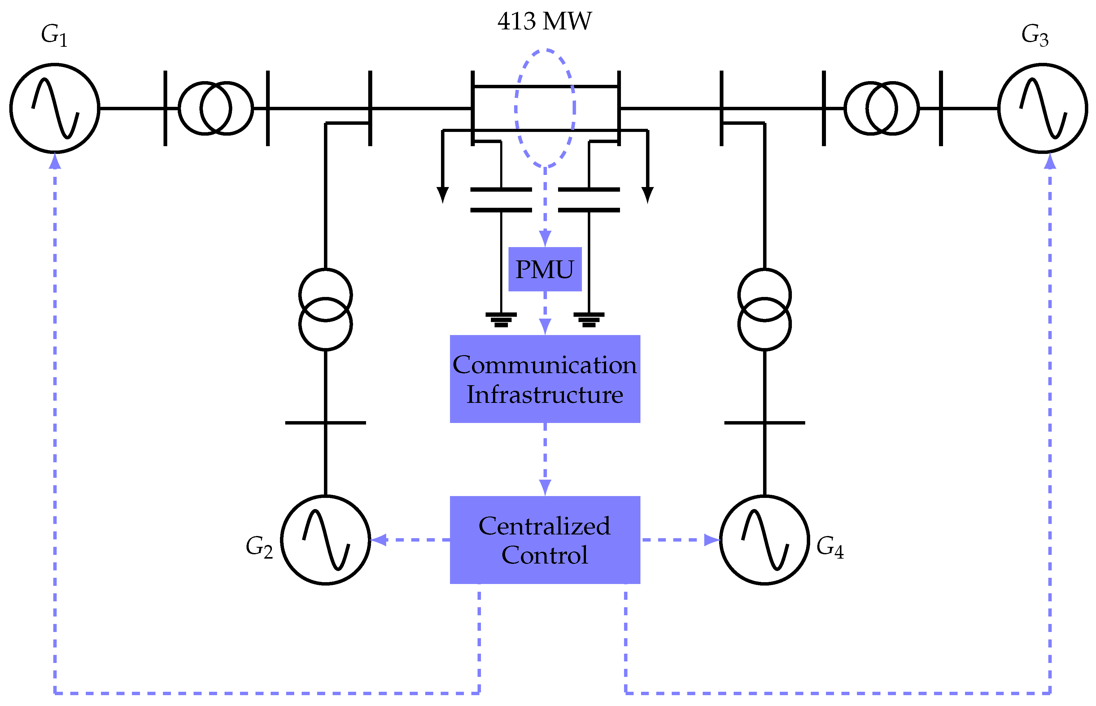
Electronics 10 00208 i001
Now, once the signals are compensated by the ETDC, the signals are brought to the robust control strategy. In the case of this work, it was used Model Predictive Control (MPC). As illustrated below, all the strategy is coherently implemented considering the functioning of the MPC. According to Figure 3, the outputs of the Power System are measured, then, data packages are sent to the control center; and they arrive with network latencies. The output and control signals are used by the Kalman filter to obtain the states. Here, ETDC acts to compensate the time-delay in order to obtain an estimation of the current states. This work’s main contribution is providing a very good estimation that allows a good performance of the closed control loop strategy. The MPC receives the estimated states to create the control sequence.
Model Predictive Control is responsible for the control task. The MPC strategy creates a time evolution of the states in a horizon of prediction using as initial condition the values of x ^ ( k i ) and the state-space model of the power system [44,45]. There, the evolution of the states are dependent from the control signals U ( k ) . Thereby, an optimal control problem is built considering an objective function and several constraints. The objective function includes minimization of efforts in control signals and the error in reference, the variable of interest here is the control signal. Physical limits and other considerations are included in the set of constrains. In this way, we derive a convex problem to be solved by any optimization technique [45,46,47]. The solution is a sequence of control signals in time, the first of which is applied to the power system. This procedure is made recursively at each sampling time using values of x ^ ( k i ) by the ETDC as the initial condition [44,45].
The whole compensation scheme proposed here, including database and SPB, is illustrated in Figure 3.
Due to the ETDC, values of time-delay for the compensation strategy has quantitative reductions that can be established by comparison of the datasets from x ^ DEL and x ^ MUA (see signals in Figure 3). As an example, we took the Gaussian test-data called D G of the Section 2 (Figure 1) and built with all the signals x ^ DEL (in Figure 3). Those signals were processed by the proposed storage block of the ETDC; so a new set of data D W was obtained (corresponding to the set of signals x ^ MUA in Figure 3). The resulting histogram of events for the D W dataset had Weibull shape with lower means values than the original sets. The dataset D W (obtained with the MUA processing) has mean value μ W = 254 ms being almost 50 ms smaller than the mean value μ G = 300 ms for the dataset D G (without the MUA processing). The data dispersion of the same set of data is also reduced and the maximum value for the latencies after the MUA processing is less than 400 ms, as Figure 4 shows. That is, while a traditional compensator is fed by signals with time-delays around 550 ms (histogram without MUA processing), with the same dataset, the ETDC will feed the SPB with time-delays under 400 ms (histogram of latencies with MUA processing) improving the performance of the compensator.
The use of the x ^ MUA information not only provokes changes in the shape of the data, but also enhances the performance of the SPB. Time-compensator routines are related with the time delay that needs to be compensated for; hence, the computational burden is lowered because x ^ MUA are less delayed. Additionally, the error in prediction is improved due to the reduction of the horizon time.
In order to offer information about the convenience of the solution based on the database added to the SPB compensation strategy, some statements are made by the authors.
Firstly, for the compensation procedure in discrete time k, a possible statement is: let Ω be an invariant set for x ( k ) and x ^ ( k ) , let X be the time evolution of real states for the autonomous system x ( k + 1 ) = f ( x ( k ) , γ ( x ( t ) ) ) , and X ^ ; the resulting trajectory of the time compensator with a representation x ^ ( k + 1 ) = F ( x ^ ( k ) ) ; both X and X ^ exist in the interval of time k i , k i + T h e and have x 0 = x ( k i ) Ω as the initial condition. T h e represents the horizon of evolution. Additionally, the relationship between f ( · ) and F ( · ) includes the error E ( · ) :
f ( · ) = F ( · ) + E ( · ) ,
Given a small scalar ϵ > 0 , and with associated value δ > 0 , which defines a set of functions β :
β = F ( x ^ ( k ) ) | F ( x ^ ( k ) ) f ( x ( k ) , γ ( x ( k ) ) ) < δ , k k i , k i + T h e ,
The states trajectory derived by the compensator satisfies the following:
X ^ X ϵ , k k i , k i + T h e ,
As such, with limited E ( · ) , it corresponds to an appropriate representation F ( · ) of the real system f ( · ) . Then, X ^ and X are close trajectories remaining in the invariant set Ω .
Secondly, regarding the error in the compensation, a statement could be formulated: let ζ = x ^ ( k i + T h e ) x ( k i + T h e ) be the error between x ^ ( k i + T h e ) and x ( k i + T h e ) at the end of the time interval k i , k i + T h e . Let k i , k i + T d b be a new interval for the evolution of x ( k ) and x ^ ( k ) . Given a small scalar value for ζ > 0 , and with the same associated value of δ > 0 for the same compact set of functions β (see Equation (9)), the final values obtained by the compensator satisfy:
x ^ ( k i + T d b ) x ( k i + T d b ) < ζ , T d b < T h e ,
This means that although the trajectories X ^ and X are close in the time interval k i , k i + T h e , there is a small value ζ > 0 , due to the error E ( · ) in the model representation. In addition, for shorter horizons of evolution T d b , the difference between the values x ^ ( k i + T d b ) and x ( k i + T d b ) at the end of the interval is limited by ζ , according to Equation (11). In practical terms: the shorter the horizons of evolution to be compensated, the lower the error in the compensated signal.
The previous statements support an important achievement owing to the ETDC reducing the value of network latencies; the compensated signals are closer to the real ones, hence they accomplish the reduction of the error.
Finally, the block diagram of Figure 5 includes the proposed ETDC into the power system control of the control center. The closed loop is built with the communication system feeding the control center, which, in turn, acts over the nonlinear power system (Equations (3)–(6)). The state estimator is also illustrated; and since the state estimator receives delayed measurements values, y ( t τ d ) , it obtains delayed values of the states x ^ ( t τ d ) . With the incorporation of the database, the strategy leads to a kind of nonlinear memory controller [48,49].

4. Application Test

4.1. Test System and Scenarios

Kundur’s benchmark system was used to validate the approach [1]. Despite its small size, this test system performances well in real inter-area oscillations due to time-delays in a single channel; in this system, we can create a scenario with oscillations specifically provoked by time-delays in WAMS. The IEEE 14 bus system and NETS 39-Bus system could be used to validate multiple channel time-delay and to control multiple sources of oscillations in furtherworks. Kundur’s test system has two coherent generation areas with four machines (Figure 6), each one with its corresponding governor and Automatic Voltage Regulator (AVR). Two tie-lines guarantee power interchange between both areas; in case of a tie-line tripping, the other one preserves the connectivity. Using the time-delay model from Section 2, the simulations for the communications of the monitoring loop were run with latencies varying from 100 ms to 500 ms [8]. During the monitoring process, a single PMU collected and transmitted data to the control center.
As illustrated in Figure 7, the block diagram of the power system to be managed is a Multiple Input Single Output (MISO) representation, in that we have a power system with four inputs (supplementary signals sent by the control scheme to the four generators) and one output measured by the WAMS (inter-area power flow).
In order to control the test system, the centralized scheme was employed with the proposed approach described in Section 3.2. As illustrated in Figure 6, the centralized controller receives the measure from the inter-area power flow, then it sends four supplementary control signals to G1, G2, G3, G4.
Two strong disturbances were simulated for the power system in a steady state. The first one consisted of a three-phase fault with a tie-line tripping; the inter-area oscillation modes took place in the test system. Then, the steady state was reached, and an additional level of higher stress was provoked with an abrupt change of power reference in the non-tripped tie line. In Figure 8, the inter-area oscillation modes are shown, excited due to the three-phase fault; the figure shows power flow response in low frequency oscillations with and without Power System Stabilizer (PSS).

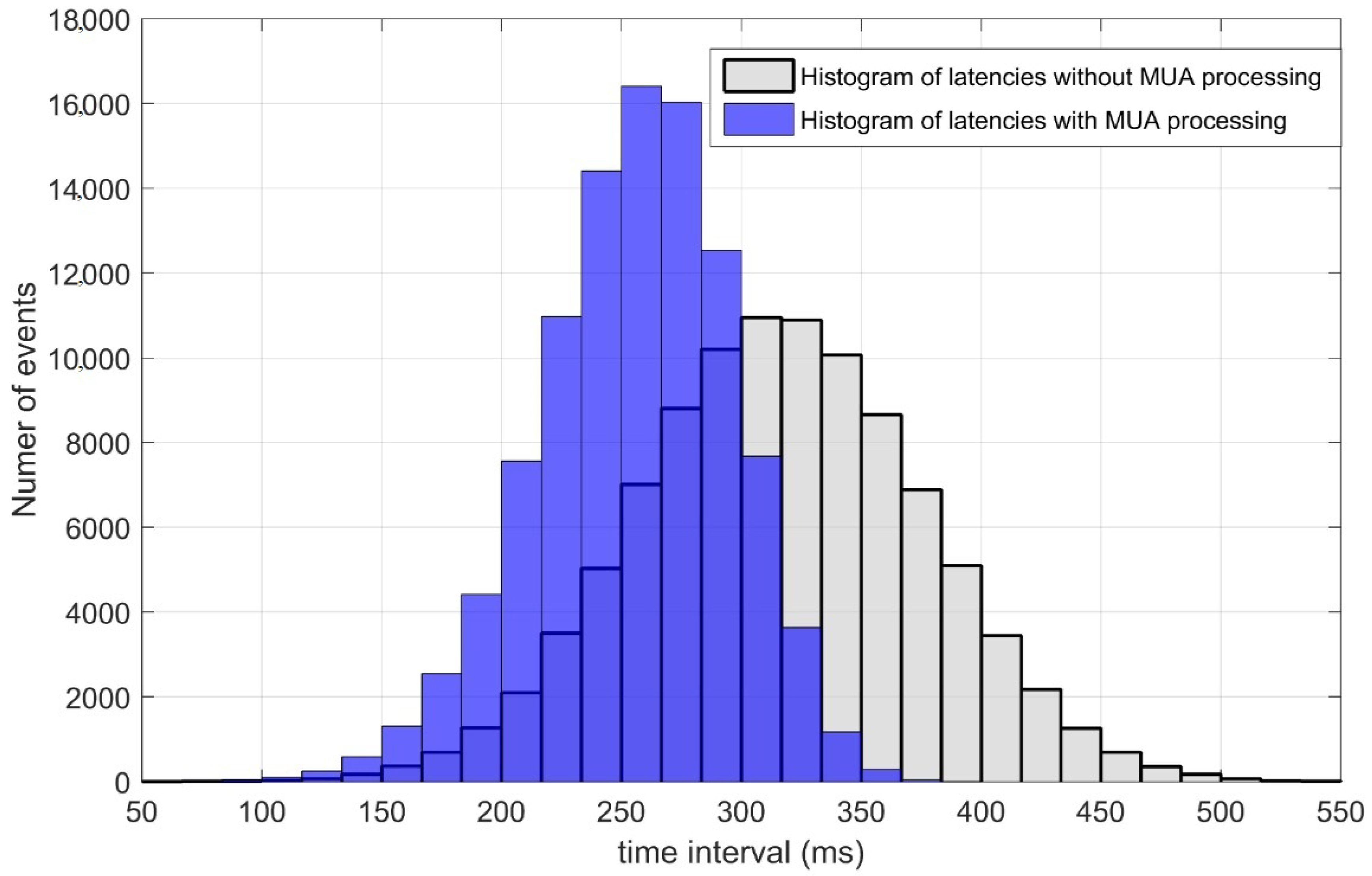
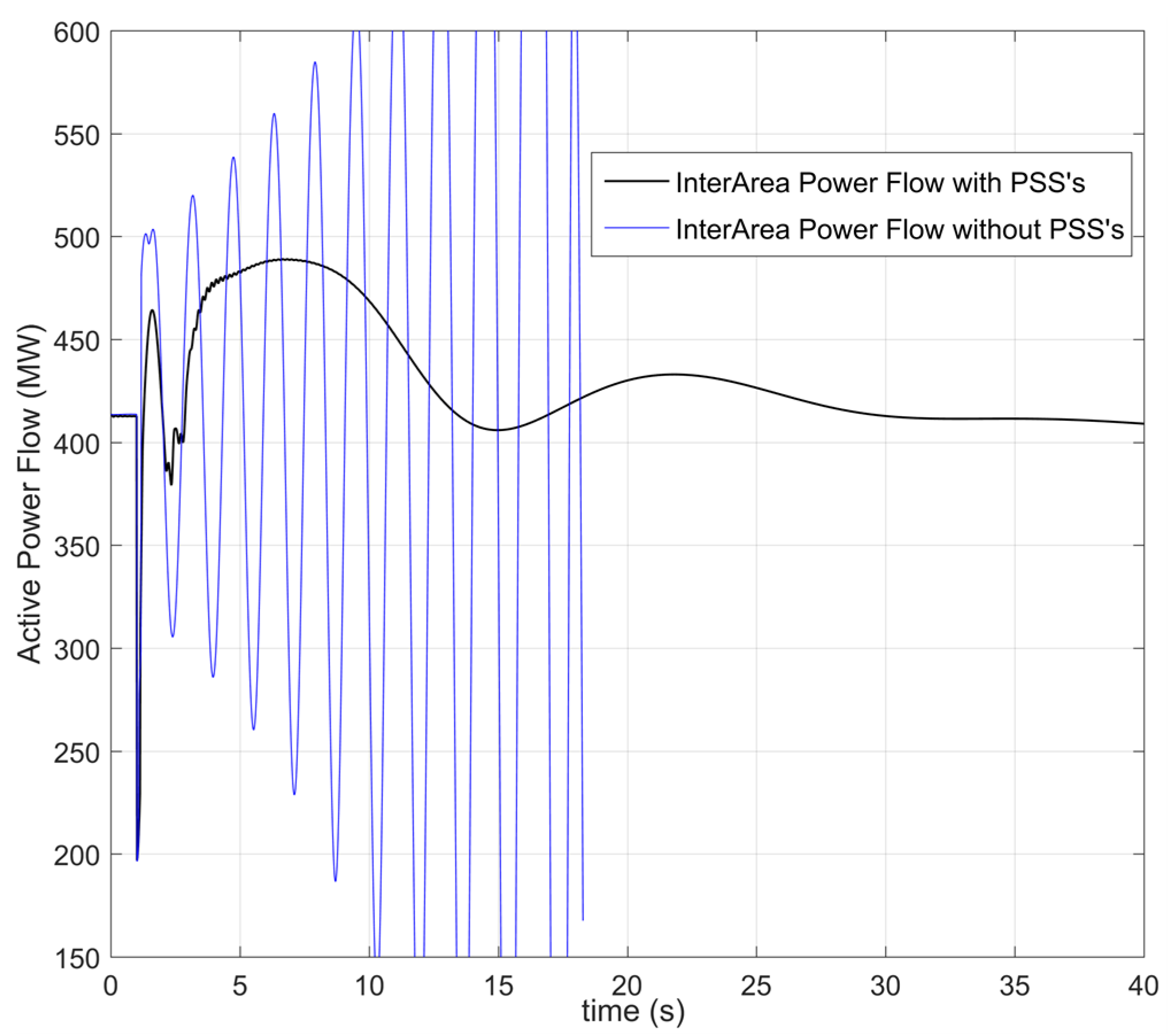
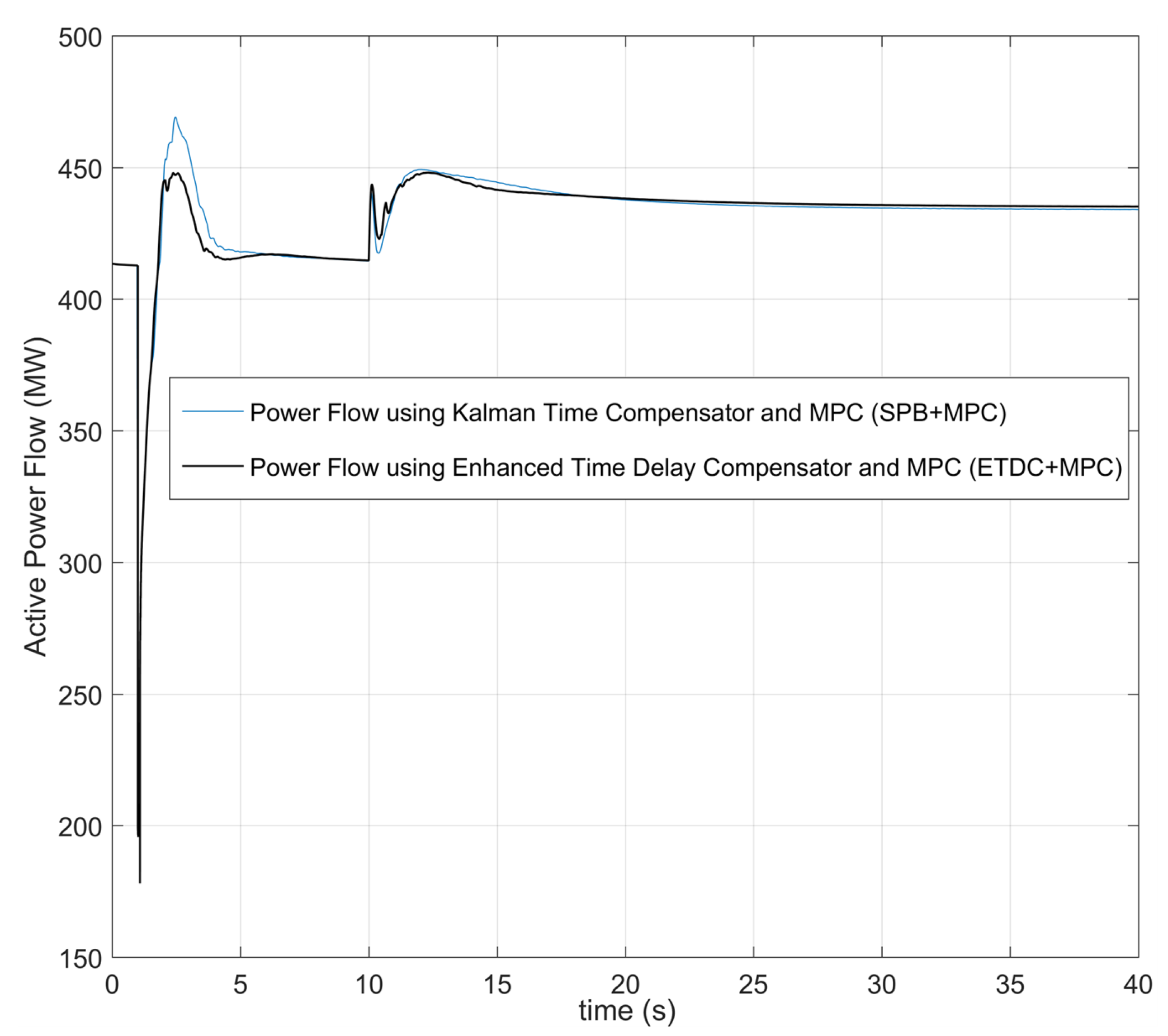
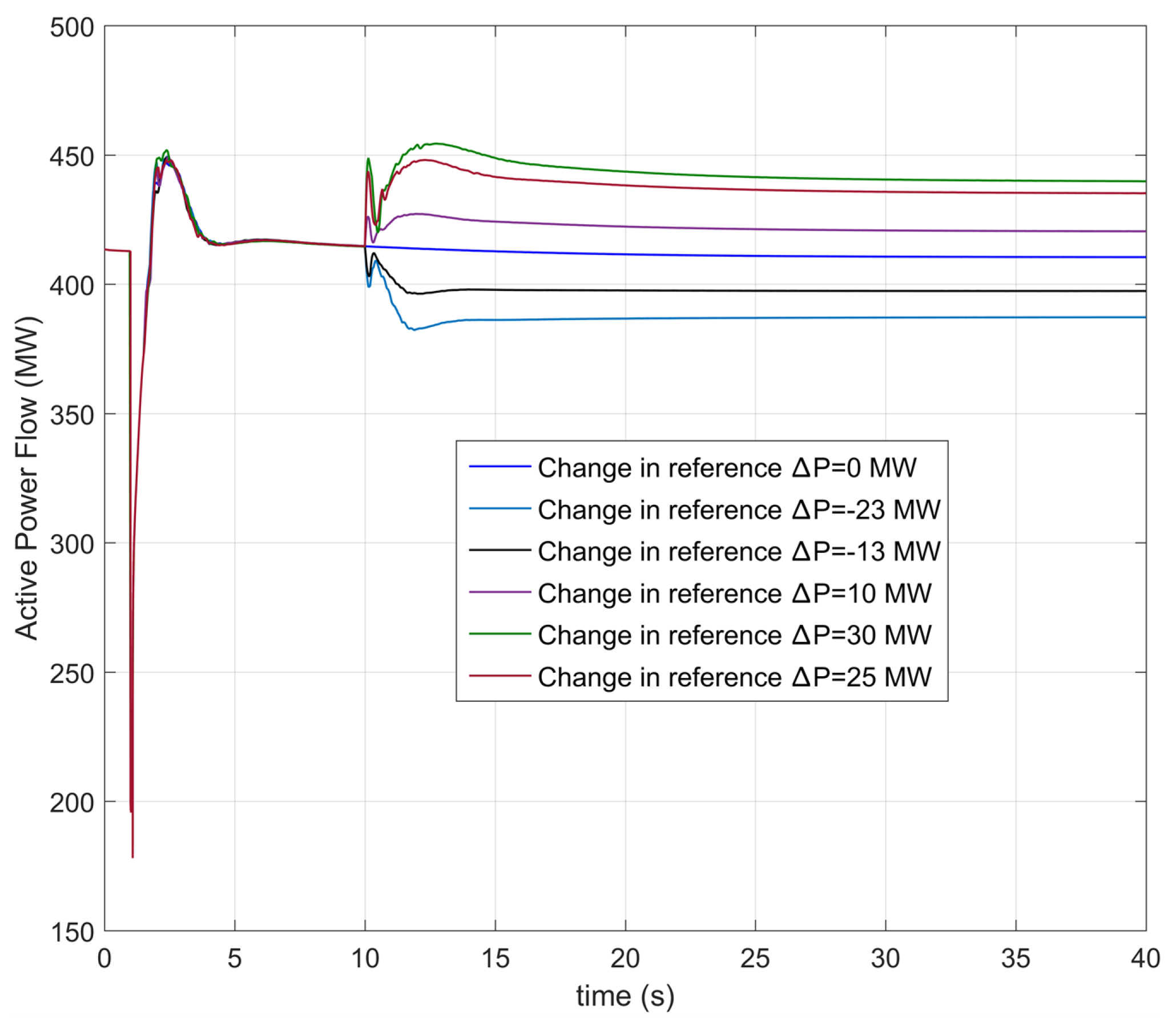
4.2. Performance Comparison between Spb + Mpc and Etdc + Mpc

Simulations were run with the same test system controlled by two different strategies: (a) the SPB + MPC and (b) the proposal of this paper ETDC + MPC. Both faced three different sequential conditions of operation: (1) initial steady state with a transferred power of 413 MW, (2) a three-phase failure at t = 1 s, (transient condition I) and (3) change of power reference with Δ P = + 25 MW at t = 10 s (transient condition II), once the system returns to steady state.
In the case of SPB + MPC, the compensation scheme considers the arriving signal with its corresponding time delay to obtain the current states without using databases. Hence, it works as a memoryless scheme of compensation and control.
Using SPB + MPC (case a), and due to the failure with line tripping, the active power flow reached a dangerous overshoot of 13.8 % at t = 2.5 s, with real value of 471 MW (Figure 9). Subsequently, SPB + MPC stabilized the power flow close to the initial pre-fault value in a time close to t = 6.2 s. With respect to the power system behavior following the change of reference ( Δ P = + 25 MW), the power flow reached a steady state with a new reference of 438 MW after undergoing a second overshoot of 2.66 % (calculated with the new reference).
Secondly, using ETDC + MPC (case b), the overshoot was 8.4 % at t = 2.5 s, with a real value of 447.6 MW (Figure 9). After the first overshoot, the ETDC + MPC reached a steady state t = 3.8 s. Then, once the reference was changed, the overshoot reached a value of 2.5 % followed by the settling time at 15 s. Table 2 illustrates the values.
Next, five different tests were performed with different changes of power reference to add more stress to the controller. The aforementioned test conditions (1)–(3) (Section 4.2) are kept for the sake of comparison. In all the cases, the overshoot after failure was less abrupt ( 8.9 % variation close to 450 MW); then, the active power reached a steady state value close to the initial power reference (see Figure 10). The error after some seconds was less than 4 MW with a downward tendency as in the previous test. At time t = 10 s, Figure 10 depicts the behavior of the power flow in the face of reference changes. The five changes in the references and their respective errors are reported in Table 3. The approach can even manage changes in references with Δ P = 30 MW.

5. Conclusions and Future Works

The communication infrastructure in power systems based on PMUs, PDCs, SPDCs, protocols, and standards create a complex but useful monitoring system. Thus, WAMS, WAC, WAMC, and finally WAMPaC can be supported by that infrastructure.
The communication infrastructure has an inherent delay due to both the devices and the links, and this issue produces instability problems in the closed loop control strategy. The model of the total latency is not deterministic but stochastic, and the shape of the time delays in typical power communication systems is Gaussian.
Use of the database derived from the MUA concept yields a delayed signal pre-processing to reduce the maximum time delay and mean values. The resulting shape of time delays after using MUA is Weibull. This implies less effort for the time compensation strategies, and, especially, the reduction of latencies leads to better convergence and performance of both the time compensator and the MPC. Improvements achieved are backed up by the results.
The database introduced complies with IEC C.37.117.7, IEC 61850 and TCP/IP, which is the underlying path of the proposed memory controller. Hence, delays were faced as network latencies instead of dead time.
The MPC with the time compensation scheme increases the transfer capabilities in tie lines on the test system; but with the enhanced time delay compensator (ETDC + MPC), it is possible to reduce overshoots and dangerous power excursions. In fact, the achieved reduction of overshoot (almost 39%) implies less stress over the thermal limits and less risk of isolating due to the activation of protection relays.
Further works should examine the performance of the tool considering larger power systems, with several channels (each one with its own stochastic time delay behavior). It is also important to consider the time delay in the control signals during the sending procedure from the control center to generators.

Author Contributions

Conceptualization, A.M.-C., M.A.R., Y.B., N.H., and O.D.M.; methodology, A.M.-C., M.A.R., Y.B., N.H., and O.D.M.; formal analysis, A.M.-C., M.A.R., Y.B., N.H., and O.D.M.; investigation, A.M.-C., M.A.R., Y.B., N.H., and O.D.M.; resources, A.M.-C., M.A.R., Y.B., N.H., and O.D.M.; writing—original draft preparation, A.M.-C., M.A.R., Y.B., N.H., and O.D.M. All authors have read and agreed to the published version of the manuscript.

Funding

The third author was supported by the Austrian Science Fund FWF (Grant M 2967).

Acknowledgments

The first author want to thank Vicerrectoria de Investigación, Innovación y Extensión from Universidad Tecnológica de Pereira for the support provided in this investigation. The fifth author want to thank to the Centro de Investigación y Desarrollo Científico de la Universidad Distrital Francisco José de Caldas under grant 1643-12-2020 associated with the project: “Desarrollo de una metodología de optimización para la gestión óptima de recursos energéticos distribuidos en redes de distribución de energía eléctrica.”

Conflicts of Interest

The authors declare no conflict of interest.

Abbreviations

Acronyms and variables
MPCModel Predictive Control
PDCPhasor Data Concentrator
SPDCSuper Phasor Data Concentrator
SPBSliding Prediction Block
PMUPhasor Measurement Unit
ETDCEnhanced Time Delay Compensator
τ d Time delay
u ( t ) Control signal
x ( t ) states of the power system
x ( t τ d ) delayed states
x ^ r ( t τ d ) delayed estimated states
WAMSWide Area Monitoring System
WAMCWide Area Monitoring and Control
WAMPaCWide Area Monitoring Protection and Control
PSSPower System Stabilizer

References

  1. Kundur, P.; Balu, N.J.; Lauby, M.G. Power System Stability and Control; McGraw-Hill: New York, NY, USA, 1994. [Google Scholar]
  2. Machowski, J.; Lubosny, Z.; Bialek, J.W.; BumbyJan, J.R. Power System Dynamics: Stability and Control; Wiley: Hoboken, NJ, USA, 2020. [Google Scholar]
  3. Mittelstadt, W.A.; Krause, P.E.; Wilson, R.E.; Overholt, P.N.; Sobajic, D.J.; Hauer, J.F.; Rizy, D.T. The DOE Wide Area Measurement System (WAMS) Project: Demonstration of dynamic information technology for the future power system. In Proceedings of the Joint Conference on Fault and Disturbance Analysis: Precise Measurement in Power Systems, Washington DC, USA, 9–11 April 1996. [Google Scholar]
  4. Ivanescu, D.; Hadjsaid, N.; Snyder, A.; Dion, J.M.; Dugard, L. Robust Stabilizing Control for an Interconnected Power System: Time Delay Approach. In Proceedings of the Fourteenth International Symposium of Mathematical Theory of Networks and Systems, Perpignan, France, 19–23 June 2000. [Google Scholar]
  5. Ivanescu, D.; Snyder, A.F.; Dion, J.M.; Dugard, L.; Georges, D.; Hadjsaid, N. Control of an Interconnected Power System: A Time Delay Approach. IFAC Proc. Vol. 2001, 34, 449–454. [Google Scholar] [CrossRef]
  6. Younis, M.R.; Iravani, R. Wide-area damping control for inter-area oscillations: A comprehensive review. In Proceedings of the 2013 IEEE Electrical Power & Energy Conference, Halifax, NS, Canada, 21–23 August 2013. [Google Scholar] [CrossRef]
  7. Aboul-Ela, M.; Sallam, A.; McCalley, J.; Fouad, A. Damping controller design for power system oscillations using global signals. IEEE Trans. Power Syst. 1996, 11, 767–773. [Google Scholar] [CrossRef]
  8. Zhu, K.; Chenine, M.; Nordström, L.; Holmström, S.; Ericsson, G. An Empirical Study of Synchrophasor Communication Delay in a Utility TCP/IP Network. Int. J. Emerging Electr. Power Syst. 2013, 14, 341–350. [Google Scholar] [CrossRef] [Green Version]
  9. Li, Y.; Yang, D.; Liu, F.; Cao, Y.; Rehtanz, C. Interconnected Power Systems; Springer: Berlin/Heidelberg, Germany, 2016. [Google Scholar] [CrossRef]
  10. Li, Y.; Zhou, Y.; Liu, F.; Cao, Y.; Rehtanz, C. Design and Implementation of Delay-Dependent Wide-Area Damping Control for Stability Enhancement of Power Systems. IEEE Trans. Smart Grid 2017, 8, 1831–1842. [Google Scholar] [CrossRef]
  11. Got Latency? Available online: https://selinc.com/solutions/synchrophasors/report/115256/ (accessed on 1 November 2012).
  12. Molina-Cabrera, A. Inter-area Oscillations in Time Delayed Power Systems: A Kalman Time Compensator and a Model Predictive Control Approach. Ph.D. Thesis, Universidad de los Andes, Bogotá D.C, Colombia, May 2018. [Google Scholar]
  13. Milano, F.; Anghel, M. Impact of Time Delays on Power System Stability. IEEE Trans. Circuits Syst. I Regul. Pap. 2012, 59, 889–900. [Google Scholar] [CrossRef]
  14. Taleb, M.; Zribi, M.; Rayan, M. On the Control of Time Delay Power Systems. Int. J. Innov. Inf. Control. 2013, 9, 769–792. [Google Scholar]
  15. Bokharaie, V.; Sipahi, R.; Milano, F. Small-signal stability analysis of delayed power system stabilizers. In Proceedings of the 2014 Power Systems Computation Conference, Wroclaw, Poland, 18–22 August 2014. [Google Scholar] [CrossRef]
  16. Snyder, A.; Ivanescu, D.; HadjSaid, N.; Georges, D.; Margotin, T. Delayed-input wide-area stability control with synchronized phasor measurements and linear matrix inequalities. In Proceedings of the 2000 Power Engineering Society Summer Meeting (Cat. No.00CH37134), Seattle, WA, USA, 16–20 July 2000. [Google Scholar] [CrossRef]
  17. Wu, H.; Tsakalis, K.; Heydt, G. Evaluation of Time Delay Effects to Wide-Area Power System Stabilizer Design. IEEE Trans. Power Syst. 2004, 19, 1935–1941. [Google Scholar] [CrossRef]
  18. Normey-Rico, J.E.; Camacho, E.F. Dead-time compensators: A survey. Control Eng. Pract. 2008, 16, 407–428. [Google Scholar] [CrossRef]
  19. Majumder, R.; Chaudhuri, B.; Pal, B.; Zhong, Q.C. A unified Smith predictor approach for power system damping control design using remote signals. IEEE Trans. Control Syst. Technol. 2005, 13, 1063–1068. [Google Scholar] [CrossRef] [Green Version]
  20. Molina-Cabrera, A.; Gomez, O.; Rios, M.A. Smith predictor based backstepping control for damping power system oscillations. In Proceedings of the 2014 IEEE PES Transmission & Distribution Conference and Exposition—Latin America (PES T&D-LA), Medellin, Colombia, 10–13 September 2014. [Google Scholar] [CrossRef]
  21. Chaudhuri, N.R.; Ray, S.; Majumder, R.; Chaudhuri, B. A New Approach to Continuous Latency Compensation With Adaptive Phasor Power Oscillation Damping Controller (POD). IEEE Trans. Power Syst. 2010, 25, 939–946. [Google Scholar] [CrossRef]
  22. Mokhtari, M.; Aminifar, F.; Nazarpour, D.; Golshannavaz, S. Wide-area power oscillation damping with a fuzzy controller compensating the continuous communication delays. IEEE Trans. Power Syst. 2013, 28, 1997–2005. [Google Scholar] [CrossRef]
  23. Yao, W.; Jiang, L.; Wen, J.Y.; Cheng, S.J.; Wu, Q.H. Networked predictive control based wide-area supplementary damping controller of SVC with communication delays compensation. In Proceedings of the 2013 IEEE Power & Energy Society General Meeting, Vancouver, BC, Canada, 21–25 July 2013. [Google Scholar] [CrossRef]
  24. Esquivel, P.; Romero, G.; Ornelas-Tellez, F.; Reyes, E.; Castañeda, C.E.; Morfin, O. Statistical inference of multivariable modal stability margins of time-delay perturbed power systems. Electr. Power Syst. Res. 2020, 181, 106186. [Google Scholar] [CrossRef]
  25. Nie, Y.; Zhang, P.; Cai, G.; Zhao, Y.; Xu, M. Unified Smith predictor compensation and optimal damping control for time-delay power system. Int. J. Electr. Power Energy Syst. 2020, 117, 1–11. [Google Scholar] [CrossRef]
  26. Nie, Y.; Zhang, P.; Cai, G.; Zhao, Y.; Xu, M. Fixed Low-Order Wide-Area Damping Controller Considering Time Delays and Power System Operation Uncertainties. IEEE Trans. Power Syst. 2020, 35, 3918–3926. [Google Scholar] [CrossRef]
  27. Nan, J.; Yao, W.; Wen, J.; Peng, Y.; Fang, J.; Ai, X.; Wen, J. Wide-area power oscillation damper for DFIG-based wind farm with communication delay and packet dropout compensation. Int. J. Electr. Power Energy Syst. 2021, 124, 1–11. [Google Scholar] [CrossRef]
  28. Ye, H.; Liu, Y. Design of model predictive controllers for adaptive damping of inter-area oscillations. Int. J. Electr. Power Energy Syst. 2013, 45, 509–518. [Google Scholar] [CrossRef]
  29. Shiroei, M.; Ranjbar, A. Supervisory predictive control of power system load frequency control. Int. J. Electr. Power Energy Syst. 2014, 61, 70–80. [Google Scholar] [CrossRef]
  30. Ma, M.; Chen, H.; Liu, X.; Allgöwer, F. Distributed model predictive load frequency control of multi-area interconnected power system. Int. J. Electr. Power Energy Syst. 2014, 62, 289–298. [Google Scholar] [CrossRef]
  31. Li, Y.; Rehtanz, C.; Yang, D.; Rüberg, S.; Häger, U. Robust high-voltage direct current stabilising control using wide-area measurement and taking transmission time delay into consideration. IET Gener. Transm. Distrib. 2011, 5, 289–297. [Google Scholar] [CrossRef]
  32. Molina-Cabrera, A.; Rios, M.A.; Velasquez, M.A. Model Predictive Control for non-linear delayed power systems. In Proceedings of the 2015 IEEE Eindhoven PowerTech, Eindhoven, The Netherlands, 29 June–2 July 2015. [Google Scholar] [CrossRef]
  33. Molina-Cabrera, A.; Rios, M.A. A Kalman Latency Compensation Strategy for Model Predictive Control to Damp Inter-Area Oscillations in Delayed Power Systems. Int. Rev. Electr. Eng. 2016, 11, 296. [Google Scholar] [CrossRef]
  34. Molina-Cabrera, A.; Rios, M.A.; Besanger, Y.; HadjSaid, N. A latencies tolerant model predictive control approach to damp Inter-area oscillations in delayed power systems. Int. J. Electr. Power Energy Syst. 2018, 98, 199–208. [Google Scholar] [CrossRef]
  35. Johnson, A.; Wen, J.; Wang, J.; Liu, E.; Hu, Y. Integrated system architecture and technology roadmap toward WAMPAC. In Proceedings of the ISGT 2011, Anaheim, CA, USA, 17–19 January 2011. [Google Scholar] [CrossRef]
  36. Ashton, P.M.; Taylor, G.A.; Irving, M.R.; Carter, A.M.; Bradley, M.E. Prospective Wide Area Monitoring of the Great Britain Transmission System using Phasor Measurement Units. In Proceedings of the 2012 IEEE Power and Energy Society General Meeting, San Diego, CA, USA, 22–26 July 2012. [Google Scholar] [CrossRef]
  37. Hossain, E.; Han, Z.; Vincent, H. Smart Grid Communications and Networking; Cambridge University Press: Cambridge, UK, 2009. [Google Scholar] [CrossRef]
  38. IEEE Standard for Synchrophasor Measurements for Power Systems. Available online: https://0-ieeexplore-ieee-org.brum.beds.ac.uk/document/6111219 (accessed on 28 December 2011).
  39. Liu, W.; Luo, H.; Li, S.; Gao, D. Investigation and Modeling of Communication Delays in Wide Area Measurement System. In Proceedings of the 2012 Asia-Pacific Power and Energy Engineering Conference, Shanghai, China, 27–29 March 2012. [Google Scholar] [CrossRef]
  40. Mohagheghi, S.; Venayagamoorthy, G.K.; Harley, R.G. Optimal Wide Area Controller and State Predictor for a Power System. IEEE Trans. Power Syst. 2007, 22, 693–705. [Google Scholar] [CrossRef]
  41. Albertos, P.; Garcia, P.; Sanz, R. Some contributions to the design of dead-time compensators. In Proceedings of the 2016 14th International Conference on Control, Automation, Robotics and Vision (ICARCV), Phuket, Thailand, 13–15 November 2016. [Google Scholar] [CrossRef]
  42. Naduvathuparambil, B.; Valenti, M.; Feliachi, A. Communication delays in wide area measurement systems. In Proceedings of the Thirty-Fourth Southeastern Symposium on System Theory (Cat. No.02EX540), Huntsville, AL, USA, 19 March 2002. [Google Scholar] [CrossRef] [Green Version]
  43. García, P.; Albertos, P. Dead-time-compensator for unstable MIMO systems with multiple time delays. J. Process Control 2010, 20, 877–884. [Google Scholar] [CrossRef]
  44. James, B.R.; David, Q.M.; Moritz, M.D. Model Predictive Control Theory And Design; Nob Hill Publishing: London, UK, 2009. [Google Scholar]
  45. Molina-Cabrera, O.D.; Gil-González, W.; Molina-Cabrera, A. Second-Order Cone Approximation for Voltage Stability Analysis in Direct Current Networks. Symmetry 2020, 12, 1587. [Google Scholar] [CrossRef]
  46. Gil-Gonzalez, W.; Serra, F.; Dominguez, J.; Campillo, J.; Montoya, O.D. Predictive Power Control for Electric Vehicle Charging Applications. In Proceedings of the 2020 IEEE ANDESCON, Quito, Ecuador, 13–16 October 2020. [Google Scholar] [CrossRef]
  47. Grisales-Noreña, W.; Molina-Cabrera, A.; Montoya, O.D.; Grisales-Noreña, L.F. An MI-SDP model for optimal location and sizing of distributed generators in DC grids that guarantees the optimal global solution. Appl. Sci. 2020, 10, 7681. [Google Scholar] [CrossRef]
  48. Rawlings, J.B.; Mayne, D.Q.; Diehl, M.M. Model Predictive Control: Theory, Computation, and Design; Nob Hill Publishing: London, UK, 2013. [Google Scholar]
  49. Boukas, E.K.; Liu, Z.K. Deterministic and Stochastic Time-Delay Systems; Birkhäuser: Boston, MA, USA, 2002. [Google Scholar] [CrossRef]
Figure 1. Typical behavior of latencies in a Phasor Measurement Unit (PMU)-based communication system.
Electronics 10 00208 g001
Figure 2. The Enhanced Time-Delay Compensator scheme.
Electronics 10 00208 g002
Figure 3. The Enhanced Time-Delay Compensator scheme.
Electronics 10 00208 g003
Figure 4. Time Delay shape after using enhanced time delay compensator (ETDC) compared with Sliding Prediction Block (SPB).
Electronics 10 00208 g004
Figure 5. ETDC + Model Predictive Control (MPC) scheme for time delayed Power Systems.
Electronics 10 00208 g005
Figure 6. Kundur’s test system with the control strategy.
Electronics 10 00208 g006
Figure 7. Multiple Input Single Output (MISO) representation of the power system.
Electronics 10 00208 g007
Figure 8. Inter-area oscillations in power flow after three-phase fault.
Electronics 10 00208 g008
Figure 9. Comparative performance using SPB + MPC and the enhanced ETDC+MPC.
Electronics 10 00208 g009
Figure 10. Power flow controlled by ETDC + MPC.
Electronics 10 00208 g010
Table 1. Ranges of Latencies in Communications [40].
Communication LinkAssociated Delay τ d (ms)
Fiber-Optic cables100–150
Microwave Links100–150
Power line carrier (PLC)150–50
Telephone lines200–300
Satellite link500–700
Table 2. Overshoot and Settling Times in the two Transient Conditions Introduced.
Transient ConditionOvershoot (%)Settling Time (s)
SPB + MPCEDTC + MPCSPB + MPCETDC + MPC
I13.88.46.23.8
II2.662.517.415.2
Table 3. Errors obtained changing references.
New Reference and Δ P (MW)Associated Error (MW)
390 ( Δ P = 23 )2.8
400 ( Δ P = 13 )2.6
413 ( Δ P = 0 )2.5
423 ( Δ P = 10 )2.5
438 ( Δ P = 25 )3.0
443 ( Δ P = 30 )3.2
Publisher’s Note: MDPI stays neutral with regard to jurisdictional claims in published maps and institutional affiliations.

