Article

Wash Analyses of Flexible and Wearable Printed Circuits for E-Textiles and Their Prediction of Damages

GEMTEX—Laboratoire de Génie et Matériaux Textiles, Ensait, University of Lille, F-59000 Lille, France
*
Author to whom correspondence should be addressed.
Submission received: 28 April 2021 / Revised: 28 May 2021 / Accepted: 4 June 2021 / Published: 7 June 2021
(This article belongs to the Special Issue Printed and Flexible Electronics)

Abstract

:
The development of specific user-based wearable smart textiles is gaining interest. The reliability and washability of e-textiles, especially electronic-based components of e-textiles, are under particular investigation nowadays. This is because e-textiles cannot be washed like normal textile products and washing electronic products is not common practice in our daily life. To adopt the e-textile products in our daily life, new standards, based on product usage, should be developed especially for flexibility and washability. The wearable motherboards are the main component for e-textile systems. They should be washing reliable and flexible for better adoption in the system. In this manuscript, flexible wearable PCBs were prepared with different conductive track widths and protected with silicone coatings. The samples were washed for 50 washing cycles in the household washing machine, and provoked damages were investigated. The PCBs were also investigated for bending tests (simulating mechanical stresses in the washing machine), and resultant damages were discussed and co-related with washing damages. The bending test was performed by bending the FPCBs at 90° over the circular rod and under the known hanging load.

1. Introduction

Textiles that are smart enough to interpret user requirements based on the designed system and type of output can be categorized as smart textiles [1,2]. In recent years, the usage of electronic components in specifically designed smart textiles, also known as e-textiles, has increased tremendously in various fields [3,4,5]. Based on specific requirements, different textile or non-textile-based electronic components are integrated with wearable textiles for users’ necessities [6,7,8,9].
For e-textiles, the possibilities in application sound promising, but there is still further work for research and development in embedding electronic components in the textile structure. The electronic components have to be reliable and robust. Hence, electronic circuit boards have gained much importance because they provide mechanical support and electrical connections to the entire electrical network. These circuit boards should be reliable and comfortable for wearable applications [10]. Flexibility is a key figure for these types of circuits, which should be compatible with the textile mechanical properties. The flexible circuits may be printed on textiles using inkjet printing [11], screen printing [5], aerosol jet printing [12], gravure printing [13], and offset printing [14]. Flexible circuits can also be prepared by using textile fabrication techniques, including embroidery and weaving [15,16]. The easiest and lowest-cost method of realizing flexible circuits is using copper-coated thin sheets to obtain the flexible circuit boards. These boards could be fixed on wearable textiles by different means, including stitching and bonding using some adhesive materials [17]. However, poor adhesion problems and flexibility mismatch with substrate create problems [15,16,18].
The use of electronics in textiles may be divided into three categories. The first-generation smart textiles include portable electronics that were inserted into pockets for a specifically designed purpose. The electronic component can be removed from the textile, but these products were usually heavier and created discomfort in their usage. In the second generation, limited electronic functionality was integrated (woven, knitted, or embroidered) in the form of interconnects, electrodes, antennas, etc. The third-generation smart textile products demonstrated increasing electronic integration levels. Flexible electronic plastic strips can be knitted or woven during the fabrication process. Electronic components may be mounted using the conductive adhesive and may be protected by glob topping to obtain better damage resistances [19].
Ma et al. [20] described various flexible electronics (energy harvesting sensors, ultrasonic flexible hybrid sensors, stimulating electrodes, flexible electrodes for nerve systems, Flexible optoelectronics device for monitoring, ultrathin electrode array, etc.,) that can be used in many smart textile applications. They concluded that flexible electronics are facing challenges in terms of more functionality in space-limited devices, flexible energy sources, and large-scale manufacturing instead of laboratory prototypes. Komolafe et al. [19] developed the flexible filament circuits for e-textile applications by various techniques. They have tested several materials, methods, and design features for handling and mounting the components to achieve maximum reliability and claimed that glob-top encapsulation performed better in washing and bending tests. Ehrmann et al. [21] discussed the single circuit boards commonly used in smart textiles. They discussed only rigid boards attached, without protections against washing damages. Fromme et al. [22] prepared the laser-welded metal textile fabric by using metal foils and thermoplastic polymers. The prepared samples were claimed to resist 42,000 flexing cycles and 10,000 abrasion cycles. However, they did not discuss the washing properties of the welded textile fabrics.
Liu et al. [23] worked on a fully printed wearable electrode textile. Conductive silver was printed on the cotton substrate, and electrodes were encapsulated with carbon paste placed in the frame. The samples were tested for 10,000 bending cycles and 20 commercial washing cycles and claimed to maintain their properties. Yang et al. [24] investigated the washable electronics based on polyamide fibrous membrane. The metal deposition for the flexible circuit board was completed by a photolithography process, and then the light-emitting diodes (LEDs) were surface mounted with soldering. They claimed the encapsulated sample stability after 50,000 abrasion cycles, 10,000 bending cycles, and 50 washing cycles. However, it is a complicated and lengthy process to carry out and, secondly, it is not suitable for large electrode component installation. In our previous research [25], we realized an e-textile T-shirt for ECG and motion detection. The electronic components were soldered on the FPCB (flexible print circuit board), which was adhered to the textile by thermoplastic polyurethane and encapsulated by polydimethylsiloxane. However, the sample could only be washed for 25 cycles. The reason for failure was not deeply investigated.
E-textile products created the interaction between different fields, including textile, electronics, telecommunications, materials, chemicals, etc. Each field has its developed expertise, and it is challenging to merge them to create a new product. The new products should be washed in corresponding standard washing procedures to withstand wearing requirements [26,27]. Well-developed standards in textiles and electronics are available; however, these standards cannot be implemented on wearable e-textiles. For the development of integrated electronic textiles, it is necessary to define new modified standards. One major hurdle related to standard adoption is washability [28]. Wearable e-textiles need to be washed regularly in the household washing machine for normal customer adoption [29,30].
This study is focused on investigating the e-textile with FPCB (flexible printed circuit board) washability problem in terms of washing and damage reliability. The FPCBs with various track widths and SMD (surface mount device) mounting positions along with protection by silicone are investigated in the study. The FPCB samples were tested for mechanical bending stresses to simulate the proposed washing damages. Finally, the relationship between the bending test and the washing test has been investigated to simulate the washing damages by the bending test. During the washing process, the insufficient resistance of the electronic components to water and the washing additives is caused by the following problems: 1. corrosion of metallic and conductive components, 2. thermal issues, 3. mechanical issues and 4. chemical stress.
Our previous work [29,31,32] highlighted these possible stresses that e-textile products bear during the washing process. The mechanical stresses could be composed of abrasion, falling, and bending stresses during the washing process. In our previous work, we have proposed to use friction and falling down tests (Martindale test and Pilling box test) to predict and washing damage without actually washing the product for transmission lines and ECG electrodes attached in the e-textile systems. The current study is the continuity of previous work and focused on the bending stress on FPCBs in an e-textile structure. The novelty of this study is in the investigation of the reliability of FPCB for e-textiles against the washing process. The FPCBs give the designer extended possibilities to achieve the more complex circuit design even with multiple layers, which allows the traditional SMD devices to be integrated into e-textiles, such as miniaturized micro-controllers, sensors, and actuators.

2. Materials and Methods

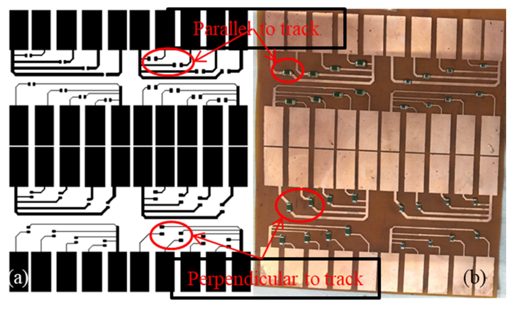
2.1. Preparation of FPCB Textile Samples
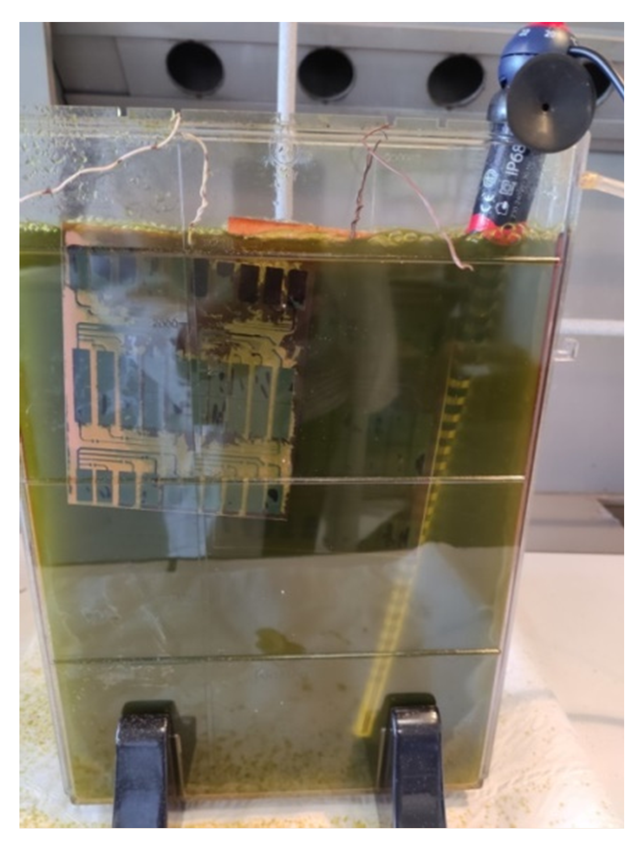
The FPCBs were prepared on the flexible single-face Copper-Kapton sheet (AN05, purchased from “CIF RETAIL”, Buc, France). Total sheet thickness was 50 μm, including 35 μm copper and 15 μm polyamide. The PCB tracks were prepared with eight different widths, including 0.15, 0.2, 0.25, 0.30, 0.45, 0.60, 0.75, and 1.00 mm. Two different sizes of 5.1 Ω SMD resistors (1206 and 0805) were mounted on the tracks. The pad size was 8 mm × 16 mm. These SMDs were mounted in two different ways, parallel and perpendicular to tracks (Figure 1). The SMD resistances in-line with conductive tracks (0° angle) are named as parallel to tracks. The resistances placed at a 90° angle to conductive tracks are called perpendicular to tracks.
The FPCB preparation was carried out in four steps. Firstly, the prepared design was printed on PNP (press and peel) blue sheet (SEEIT SARL, Clermont-Ferrand, France). Then, the printed circuit was thermally transferred on the flexible single-face copper sheet (Figure 1). The thermal transfer process was carried out at 170 °C for 180 s. In the third step, the etching process was carried out. A printed flexible single-face copper sheet was immersed in FeCl3 solution carried in a vertical etching tank (Figure 2) until the copper layer, other than that covered by a printed area on the sheet, was dissolved in the FeCl3 solution. These sheets were then completely washed with distilled water and dried. Finally, SMD resistors were mounted on the prepared sheet using conductive paste (MOB39, MBO solder, Chevigny-Saint-Sauveur, France). The process is carried out using the heated air pump (Toolcraft) by adjusting the heated air temperature at 300 °C.
The prepared FPCB samples were fixed to the cotton fabric by silicone adhesive coating (Bluesil™ TCS 7550, ELKEM, Leverkusen, Germany). The two-part silicone was mixed in the 1:1 by weight ratio as described by the supplier. After mixing it thoroughly, the solution was placed in the vacuum tank to remove air bubbles from the silicon solution, to avoid holes in the dried silicon after settlement. Here, the silicone solution was used for two purposes, an adhesive layer, and a protective encapsulation layer. For adhesive purposes, a thin silicon solution layer was placed on the cotton fabric, and the FPCB sample was placed on it under a 2 kg load for 5 min at 80 °C. For encapsulation purposes, the silicone solution was poured on the FPCB sample, and the sample was kept in the oven for 4–5 min at 80 °C.
Overall, FPCB samples were prepared in three different types, non-protected samples, silicone encapsulated samples, and semi-encapsulated samples (only at SMD resistance joining points). Each FPCB was divided into eight small parts having four different tracks along with SMD on them. Overall, 32 SMD resistors (50% for parallel and 50% for perpendicular placement) were attached to the FPCB. In total, 8 different track widths (four for each size) were used for 32 SMD resistors. Among the 32 SMD resistors, 50% were 0805 sizes, and the remaining 50% were 1205 size type. A detailed explanation of samples used in each type of test is presented in Table 1. In total, 6 sets of samples were used for washing tests (Silk and Express), and 2 sets of samples were used for bending tests.

2.2. Washing Tests

The washing tests were realized by the MIELE W3240 household washing machine with two programs (Silk and Express). The washing programs are decided based on the previous work where detailed washing analysis was performed [30]. Both cycles have a total process time of 35 min but different normal washing speeds, 15 RPM in Silk washing, and it is 38.5 RPM in Express washing cycle. Actual running time is also varied in both programs, 27% for the Silk washing program and 67% for Express washing [30]. Both washing programs were performed at 40 °C and commercially available detergent (Total-X.TRA) was used according to ISO 6330 standards. The samples were washed along with 2 kg of cotton and polyester textile washing ballast load as explained in ISO 6330 standards.

2.3. Bending Test

The bending tests were realized by using a double-acting pneumatic round line cylinder (Figure 3). The double-acting cylinder performed a backward and forward movement to the attached long rod. Fabric containing FPCBs was fixed from one side, and a hanging weight of 1 kg was attached on the other side. FPCB was bending around the circular road of 12 mm diameter with forwarding and backward movements at a speed of 80 cycles per minute. Bending tests were performed on non-protected and completely silicone encapsulated samples only. Semi-encapsulated samples were not used in these tests because they were completely damaged in the washing tests, so they were excluded from bending tests.
In this study, the abrasion test (Martindale test) was not carried out because the FPCBs are usually not directly exposed to abrasion stress since they are not designed to contact the skin directly in the e-textile systems. Meanwhile, as for the falling down test (Pilling box test), since the damage of shock is negligible during the washing process as the SMD is solid and the direct result of falling is the risk of bending, the falling test was not performed. Moreover, flexibility is a vital property for better adoption in wearable e-textile systems. The FPCBs should perform bending resistance to claim the required flexibility for e-textile systems. That is the reason that we only performed a bending test in this study.

2.4. Electrical Resistance Measurement

Electrical resistance for resistors was measured using the Agilent 34401A digital multimeter. Each resistor had a separate set of measuring pads (8 mm × 16 mm) used for this purpose.

3. Results and Discussion

FPCB was tested for washing and bending tests, and resultant damages for SMD adhesion with the surface and FPCB tracks were discussed.

3.1. Flexural Rigidity Tests

First of all, a flexural rigidity test was performed on these FPCB samples with and without silicone protection. Bending length was measured by using the wooden stiffness tester designed for textile testing according to ISO 9073-7 (Test Methods for Nonwovens). In this experiment, a rectangular strip supported on the horizontal platform was advanced from the edge in the direction of its length until the increased part bends down under its weight at the angle of 41.5°. Flexural rigidity was then calculated using the equation (G = m × C3 × 10−3). Here, m is the mass of specimen per unit area (g/m) and C is the bending length (cm) of the test specimen.
Initial flexural rigidity for the cotton fabric used for these experiments was 0.028 mN. Prepared FPCB without any protection showed the flexural rigidity of 2.4 mN. However, this flexible rigidity was increased to 12.62 mN when a silicone protective layer was added to the FPCBs. Hence, it was not easy to be bent during the mechanical actions and washing actions.

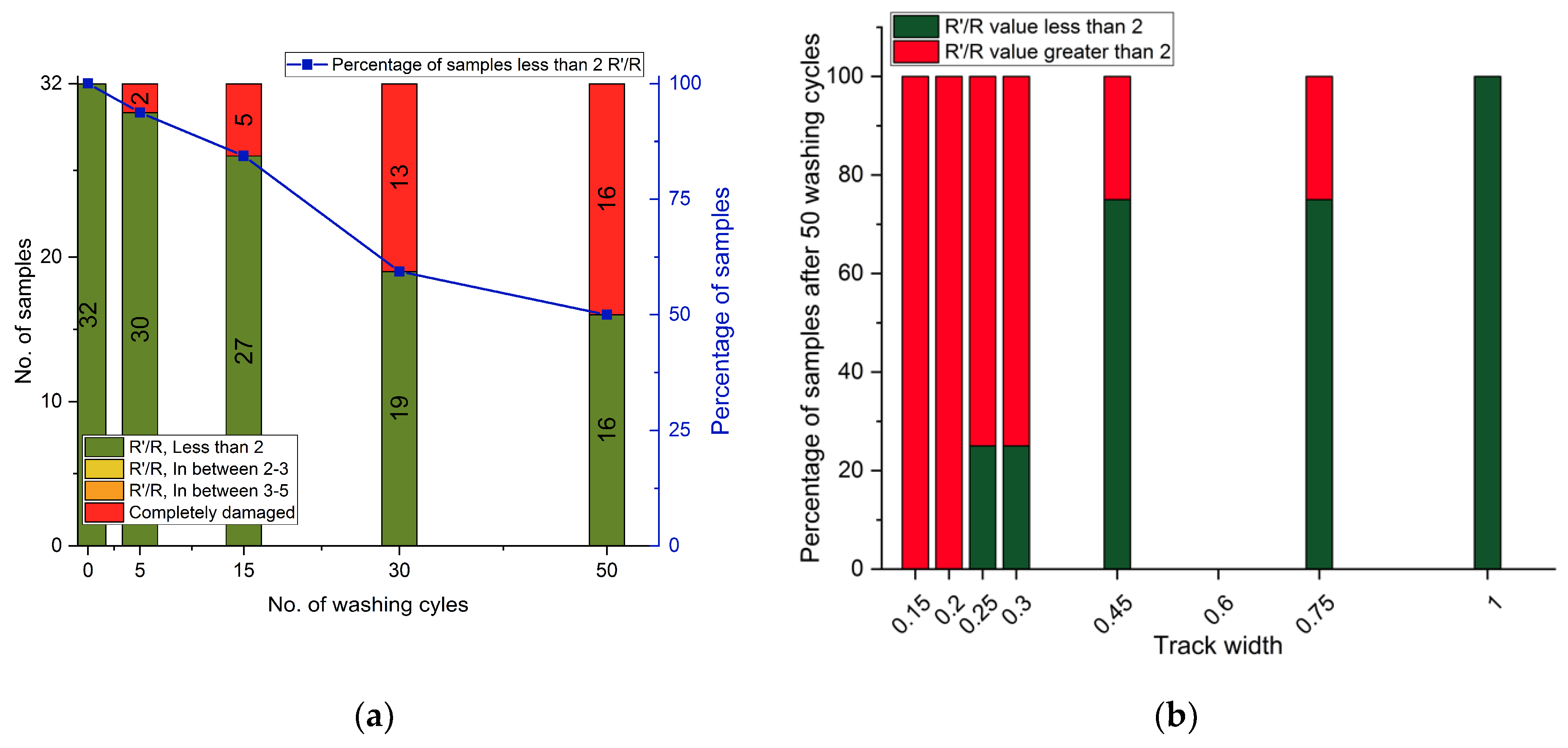
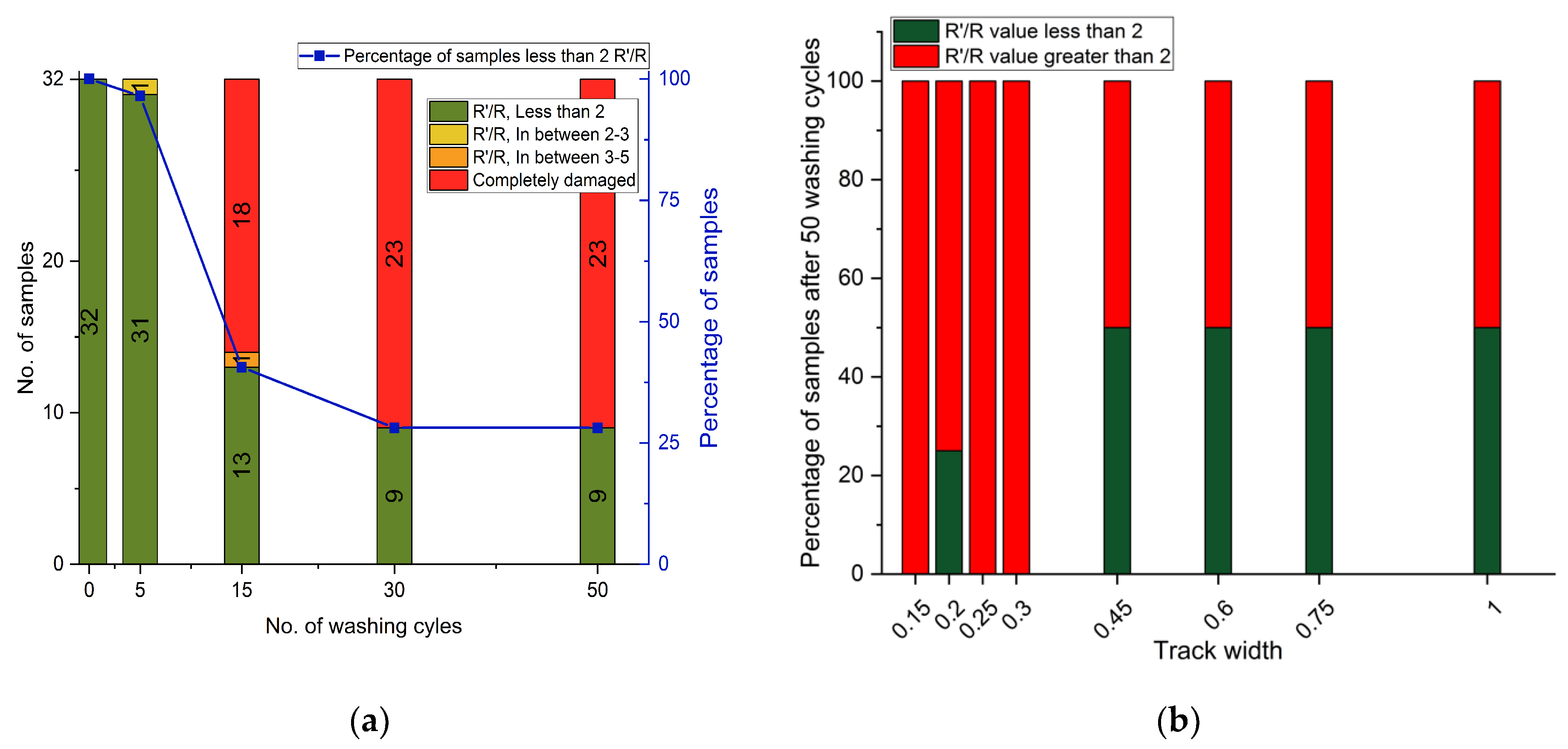
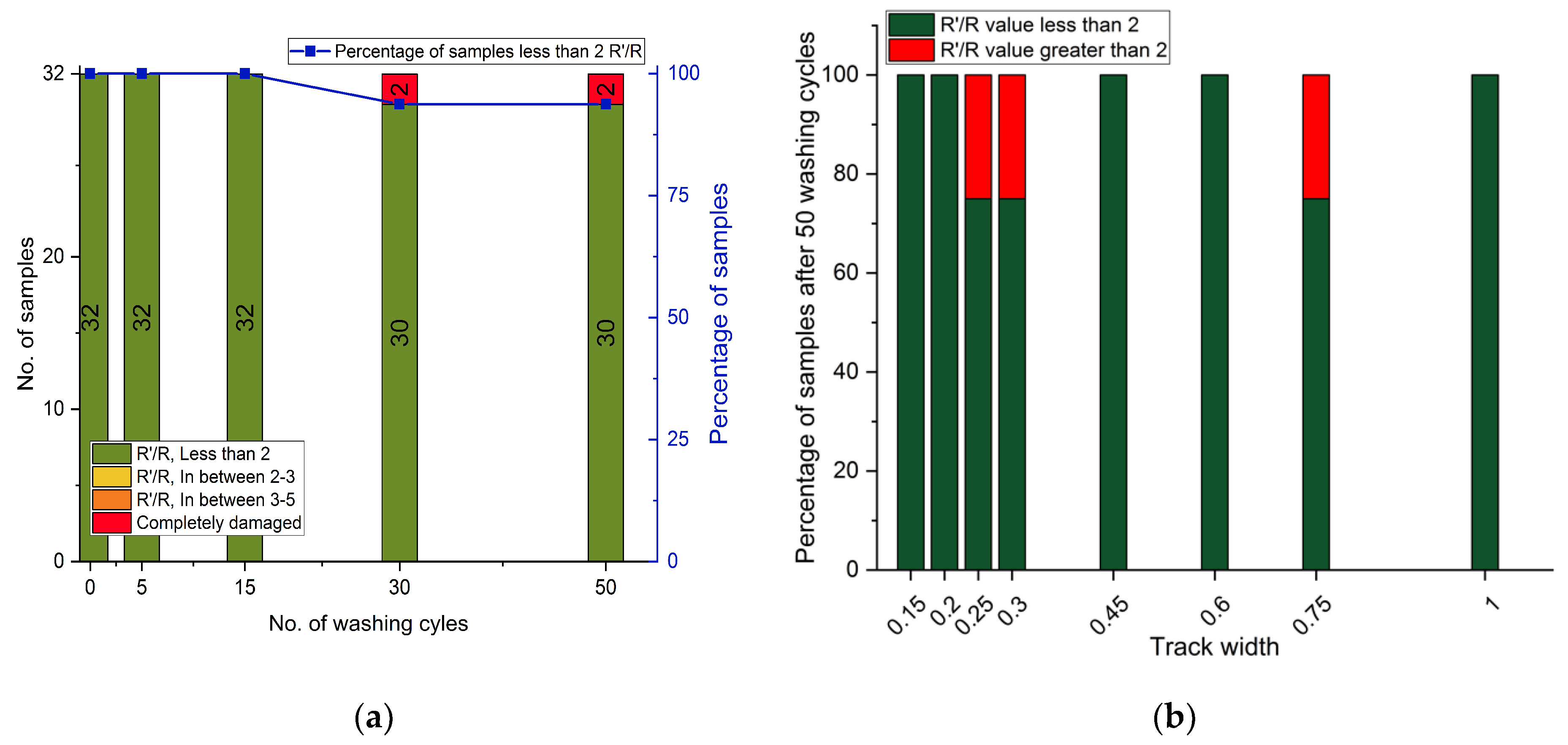
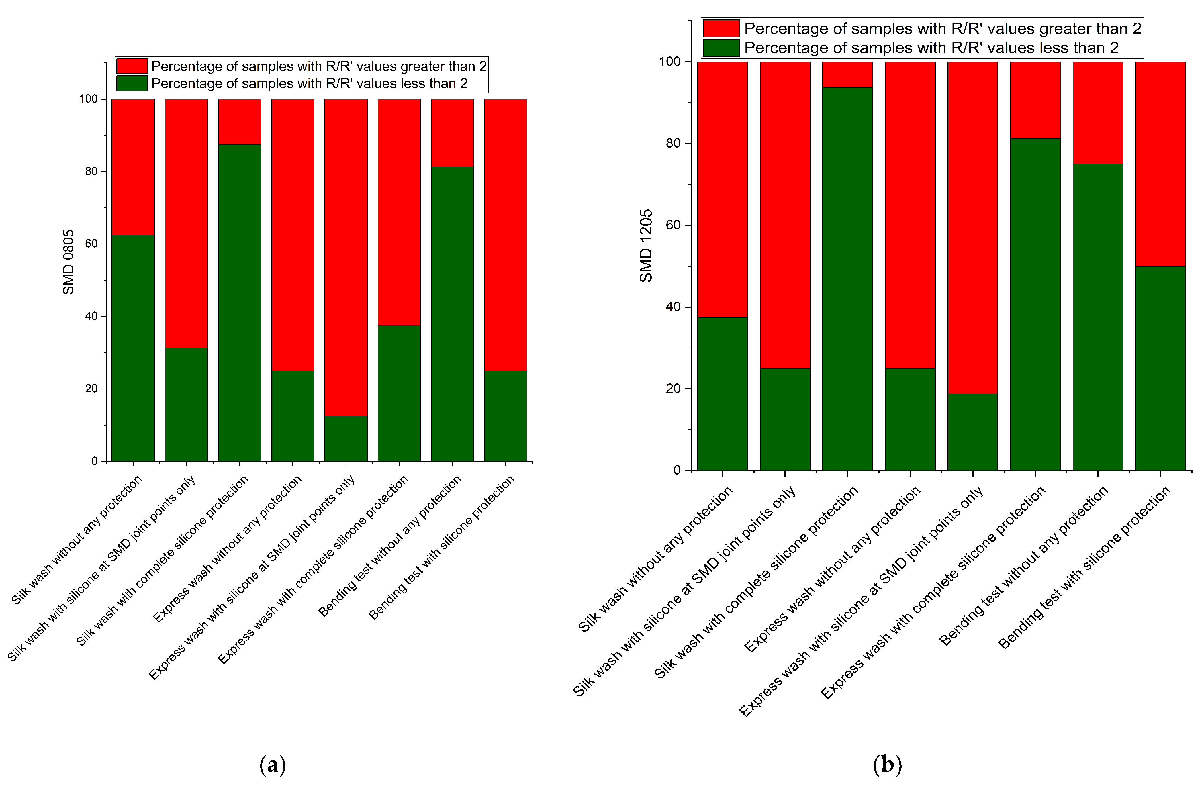
3.2. Result of Express and Silk Washing Tests

Figure 4a and Figure S1 describe the 40 Express washing cycle’s impacts on the FPCBs without any protection. In total, 75% of samples were wholly damaged, and resistance output was not detected. However, the remaining ones (25%) were in good condition (Figure 4a), and their R’/R (ratio of change in resistance from initial resistance) was almost the same after 40 washing cycles. Express washing experiments were stopped after 40 washing cycles as 75% of samples were damaged. R’/R value was calculated by removing the destroyed samples, and only working samples were included in the mean values. Samples increased their electrical resistances before they were completely damaged, and these higher values were included in R’/R values until they were destroyed. After 20 washing cycles, 75% of samples were working, but some of them started to deteriorate and increased their R’/R values, which caused the unexpected increase in the error bar. However, when they were destroyed and removed from the standard deviation, the associated errors ranged again with smaller standard deviations. (Logically, the samples with the highest standard deviations have been destroyed first and removed from the measurements.)
In terms of damages on the different track widths, nearly all types of FPCB tracks were damaged after 40 Express washing cycles, except for 1.00 and 0.45 mm (25% and 50% of samples were working, respectively (Figure 4b and Figure S2)). In terms of SMD positions on the FPCBs, samples with parallel to tracks SMD resistances were more damaged (93%) than perpendicular tracks (60%).
As for the semi-encapsulated samples, their results show almost the same trend as the results of unprotected samples. More than 75% of samples were damaged after 40 washing cycles. The remaining pieces showed nearly no change in R’/R value after 40 washing cycles (Figure 5a and Figure S3). From the perspective of track width, all samples were damaged, except for 1.00, 0.75, and 0.45 mm track widths, which showed little resistance to these washing stresses (Figure 5b and Figure S4). In the comparison of SMD position, FPCBs with SMD resistances mounted parallel to tracks are more damaged, and all samples were entirely damaged compared to the perpendicular ones, where almost 60% of samples were destroyed.
As for the encapsulated samples, the silicone coating increased the resistance against provoked damages in the washing process. Only 4 samples (12%) were destroyed after 50 Express washing cycles (Figure 6a and Figure S5). Eight samples, among the remaining, increased their R’/R values above 2 and one sample above 3, but still, all the samples were working in good condition. Overall, more than 80% of samples have R’/R values less than 2 after 50 washing cycles. However, average R’/R values for working samples increased because more than 80% of samples were in working conditions, but somehow, they increased their resistance.
The samples with higher width tracks showed better results in all, and only a few were damaged. Samples with 0.3 and 0.25 mm track width showed the highest damage ratio, and 100% and 75% samples increased their R’/R values above 2, respectively (Figure 6b and Figure S6).
Figure 7a and Figure S7 highlight the non-protected FPCB samples washed in Silk washing cycles. Almost 50% of samples were damaged after 50 washing cycles, and the remaining were in good condition with negligible average R’/R value change. Samples with smaller track widths were damaged more intensively; 80% of samples were destroyed. FPCBs with a 1 mm track width showed the best results without any damage (Figure 7b and Figure S8). Comparing the parallel and perpendicular mounted SMD samples, both types of prototypes showed almost equal damages, about 50–60% of samples were damaged.
In FPCBs with silicon coating on SMD mounting point only, about 75% of samples were damaged after 50 Silk washing cycles (Figure 8a and Figure S9). This ratio is much higher than models without any protection. When we discussed the results based on the track width, samples with smaller track widths were almost wholly damaged. Higher track widths (from 0.45 to 1.00 mm) were nearly 50% damaged (Figure 8b and Figure S10). In parallel and perpendicular mounted samples, 100% of samples with parallel mounted SMDs were destroyed, and 50% in perpendicular ones.
Completely silicone-protected samples showed the best results after 50 Silk washing cycles and indeed the best results in overall experiments. In total, 94% of samples showed their R’/R values below 2, and only two samples were damaged (Figure 9a and Figure S11). In two damaged samples, one was parallel mounted, and the other was a perpendicular mounted sample (Figure 9b and Figure S12).
Figure 10a compares the resultant damages in terms of types of SMD used (0805 and 1205). Percentages of samples with R’/R values above and below 2, after complete washing and bending tests, are presented in the graphs. Both graphs showed the same trend and we can conclude that SMD type did not impact the washing reliability of FPCB samples.
Damages provoked by the washing stresses at random points in the FPCB samples are shown in Figure 11. Cracks are visible in these pictures highlighted with circles. They can be divided into three categories: the cracks in the track lines, at the SMD pasting point, and the joint position of track lines and measuring pads.
Different track widths were investigated in the experiments. Tracks with a thinner width were more provoked to the damages and vice versa. Tracks usually above 0.45 mm were better in performance in all experiments compared to the thinner ones. Although, track width and spacing are designed based on the requirement and directly impact the manufacturing costs. However, for the FPCBs’ reliability, an appropriate track width that can withstand possible mechanical damages should be considered. SMD resistances were placed parallel and perpendicular to the FPCB tracks to investigate the impact of their positions in the washing damages. For the samples with complete silicon protections, SMD resistances’ position is not concerned because all the samples were well protected and did not show any damage. However, for the examples without protections, SMD resistances, placed parallel to the FPCB tracks, were relatively more damaged than the perpendicularly placed resistances. Nevertheless, these samples were more than 50% destroyed in both cases, so we cannot state that SMDs in one direction are better than SMDs in the other one. However, for the reliability performance of e-textile systems, circuit designs and positions of installed SMDs should be considered.
During the washing process, samples had undergone various mechanical stresses, including bending, twisting, and shearing. These stresses impacted more intensively at the flexible surface with a rigid SMD joint [33,34,35]. Conductive paste along with rigid SMD increased the hardness of the FPCB at that specific point. A sharp decrease in the flexibility enhanced the probability of mismatch, and the resultant concentration of the stress caused the creation of cracks (Figure 12). The mismatch is also possibly created between copper material used for the printing of tracks and base material. The mismatch is further enhanced at the connection pad joint where printed copper width is reduced from 20 to 1 mm, or even 0.15 mm in some cases.
When we discuss all results after the washing process, samples completely protected by silicone coating showed the best results, which is pretty straightforward because the coating protected the samples from all possible damages during the washing process. The silicone coating also reduced the surface mismatch problem because the complete FPCB circuit was covered with this coating. The silicone coating covered all the FPCB area, and the flexibility differences problem between FPCB and SMD was avoided. Hence, surface morphology and flexibility were the same for the sample as a whole. Among Silk and Express washing cycles, the Silk washing cycles have less impact on the samples’ reliability due to their mild washing behavior during the process.
Secondly, when complete FPCB was protected by silicone coating, it was difficult for it to bend during the washing process because flexural rigidity was increased to 12.62 mN·cm from 2.4. The FPCB was placed on the cotton fabric, having a flexural rigidity of 0.028 mN·cm, which increased to 2.4 mN·cm when FPCBs were attached to it. This increased rigidity saved the FPCBs from multiple bends during the washing process, and hence mechanical stresses acting on samples were reduced.
Samples without protections and with protections at the SMD pasting point only later showed the worst results, even if they were somewhat protected when compared with non-protected ones. The surface mismatch problem was highlighted again, and it was even amplified due to silicon coating at some random points in the FPCBs. The silicone coating was placed with the idea to protect the SMDs and their joints from possible damages. However, the silicone coating caused a reduction in the flexibility at various points on the FPCB. Hence, the flexibility mismatches problem between flexible and semi-flexible surfaces and resultant damages enhanced, although SMD joint points were protected. That is the reason why these samples showed the minimum numbers of working pieces after 50 washing cycles for both Silk and Express washing cycles.

3.3. Results of Bending Tests

As for the unprotected samples, their average R’/R value, up to 12,000 cycles, was approximately 1.5, and 75% of samples among them have R’/R values less than 2. FPCB damage started beyond this level, and 62% of them increased R’/R values above 2 after 20,000 bending cycles, with actually 34% of samples above 5. The average R’/R value after 20,000 bending cycles was increased to 4.5. This value is relatively high when compared with washing test analysis. In washing tests, the majority of samples were damaged entirely and hence removed from average values. But in the bending test case, no sample was damaged. They increased their electrical resistance values after specific bending cycles. Hence, a significant increase in the average R’/R value for these samples was observed (Figure 13a and Figure S13).
When we compare track widths for different samples, it was observed that models with thinner track widths were more impacted compared to thicker ones, and their R’/R values were increased beyond the threshold level of 2. Samples with track widths of 0.45 mm and higher showed better resistance against bending cycles, and more than 50% of samples maintained their R’/R values below 2 (Figure 13b and Figure S14). The SMDs position in the design did not impact the bending damages, and they were equally destroyed.
As for totally silicone-protected samples, 94% of them showed R’/R values less than 2 after 16,000 bending cycles (Figure 14a and Figure S15). After 16,000 cycles, samples started increasing their R’/R values and reached 5 after 20,000 bending cycles. However, only 25% of samples increased their R’/R values, and the remaining 75% of samples were in a good condition with R’/R values less than 2. In comparison to track widths, samples with lesser track widths were more damaged, and it is understandable because smaller track widths have a less conductive area, and only a small crack can destroy all the current passing paths (Figure 14b and Figure S16). Here, again, SMD position (parallel and perpendicular) did not impact, and both types of samples were equally damaged.
Bending tests showed the same kind of trend as in the washing experiments. The Surface mismatch problems were highlighted at SMD pasting points. In the bending test, no sample was utterly damaged, but their overall electrical resistance was increased. Most of the tracks were in good condition, but resistance was increased due to the damage at the SMD pasting point. The bending test damaged the soldering paste used for adhesion between the SMD and FPCBs because of the continuous bending around the circular rod. Silver paste, along with SMD, reduced the flexibility at that certain point, and bending was difficult at that specific point. The adhesion between SMD and silver paste was weak but was still in contact, causing increased electrical resistance instead of, ultimately, damage, as rendered in the washing tests [33,36].
A comparison analysis to co-relate the damages among all samples is shown in Figure 15. Washing samples protected with silicone coating presented the best results in all experiments following the examples without any protection. Semi-encapsulated samples were more vulnerable in the washing tests. Prototypes with the Silk washing cycles were on the top of Figure 15 (and Figure S17) due to mild washing forces acting during the process. Bending test results were between the range of silicon-coated and non-coated samples and may be used to co-relate the equaling damages as provoked in the washing process. For example, in these samples, we can predict that silicone-coated specimens washed with 40 Express washing cycles produced equivalent damages caused by 20,000 bending cycles on silicone-coated samples. Similarly, silicone-protected samples with 50 Silk washing cycles provoked similar damages as 16,000 bending cycles performed on protected samples. The presented analysis will be different for different types of products and vary depending on the end-user requirements. However, these predictions will help the e-textile industry to reach a joint agreement between companies willing to develop the e-textile products adopted in the textile industry.

4. Conclusions

The research was performed to discuss and highlight the washing problems in e-textile systems. The FPCBs were prepared and tested by various track thicknesses against the washing and mechanical stresses. It was observed that thinner track widths were more ready to damages compared to the thicker ones. The washing reliability can be altered by changing the required track widths. Samples with track widths greater than 0.45 mm showed better performance against the washing and mechanical damages compared to the widths less than 0.45 mm. Hence, we can conclude that FPCB should be prepared with a minimum track width of 0.45 mm.
The FPCBs were also tested against different SMD positions (parallel and perpendicular) in the circuit. Both types of samples almost showed equal results in all experiments. Hence, we can state that the position of SMD in the circuit did not impact the washing reliability of the prepared FPCB and we can say that SMD can be placed in any suitable positions according to the circuit design. Two types of SMD (0805 and 1205) are used in the experiments. In comparison, both types of SMDs showed similar types of damages in all tests performed, and hence, we can state that the type of SMD used did not impact the washing reliability of these FPCBs.
The prepared FPCBs were also tested against two different types of silicone protections (fully encapsulated with silicone and semi-encapsulated). The prepared FPCBs were protected with a silicone coating to minimize the surface mismatch between the base material and printed design and SMD mounted pads. It was observed that protected PCBs could withstand 50 washing cycles without any major damage to the circuit. The samples were also investigated with 20,000 bending test cycles, and produced damages were investigated. It can be stated that the FPCB samples withstand bending stresses up to 12,000 bending cycles, and then they start degrading. Silicone-protected samples even enhanced the values up to 16,000 bending cycles before damage started. The alternate mechanical test protocols may be used to predict the proposed damages without washing the samples. We can assume that damages provoked by 40 Express washing cycles are equal to the 20,000 bending cycles. Although, these predictions are sample-specific and will vary in different e-textile systems and their reliability requirements. The alternate methods may help the electronic industry develop the electronic components for e-textile systems without any fear of rejection.
Finally, we can propose suggestions and the possible parameters that should be considered during the FPCB preparations. The FPCBs should be designed with at least a minimum track width of 0.45 mm. The size and position of SMDs can be adjusted according to the requirements, as they did not impact the FPCB performance. However, the FPCBs should be completely protected with some silicone or any alternative coatings to protect them from washing and other mechanical damages. The protective layer should cover complete FPCB to avoid any flexibility mismatch problems. In future, further protective techniques should also be tested to protect the FPCBs without compromising the flexibility of the samples. TPU (thermoplastic polyurethane) sheet can also be used for protecting the FPCBs. Similarly, various SMD sizes should also be investigated to find the best possible composition for reliable and washable FPCBs. Different SMD adhesion techniques should also be studied to enhance the joint point resistance against possible washing and mechanical damages. These suggestions may be helpful for electronics or other industries that are willing to design the FPCBs compatible with flexible textile structures.

Supplementary Materials

The following are available online at https://0-www-mdpi-com.brum.beds.ac.uk/article/10.3390/electronics10111362/s1, Figure S1: FPCBs sample (without any protection) analyses after 40 Express washing cycles, a total of 32 samples were tested, (a) percentage of samples with R’/R value above 2 described based on track widths, (b) average R’/R value of working samples only, Figure S2: FPCBs sample (without any protection) analyses after 40 Express washing cycles, a total of 32 samples were tested, (a) samples with SMDs mounted perpendicular to tracks, (b) samples with SMDs mounted parallel to tracks, Figure S3: FPCBs sample (with silicone protection at SMD joints only) analyses after 40 Express washing cycles, a total of 32 samples were tested, (a) percentage of samples with R’/R value above 2 described based on track widths, (b) average R’/R value of working samples only, Figure S4: FPCBs sample (with silicone protection at SMD joints only) analyses after 40 Express washing cycles, a total of 32 samples were tested, (a) samples with SMDs mounted perpendicular to tracks, (b) samples with SMDs mounted parallel to tracks, Figure S5: FPCBs sample (with silicone protection completely) analyses after 50 Express washing cycles, a total of 32 samples were tested, (a) percentage of samples with R’/R value above 2 described based on track widths (b) average R’/R value of working samples only, Figure S6: FPCBs sample (with silicone protection completely) analyses after 40 Express washing cycles, a total of 32 samples were tested, (a) samples with SMDs mounted perpendicular to tracks, (b) samples with SMDs mounted parallel to tracks, Figure S7: FPCBs sample (without any protection) analyses after 50 Silk washing cycles, a total of 32 samples were tested, (a) percentage of samples with R’/R value above 2 described based on track widths, (b) average R’/R value of working samples only, Figure S8: FPCBs sample (without any protection) analyses after 50 Silk washing cycles, a total of 32 samples were tested, (a) samples with SMDs mounted perpendicular to tracks, (b) samples with SMDs mounted parallel to tracks, Figure S9: FPCBs sample (with silicone protection at SMD joints only) analyses after 50 Silk washing cycles, a total of 32 samples were tested, (a) percentage of samples with R’/R value above 2 described based on track widths, (b) average R’/R value of working samples only, Figure S10: FPCBs sample (with silicone protection at SMD joints only) analyses after 50 Silk washing cycles, a total of 32 samples were tested, (a) samples with SMDs mounted perpendicular to tracks, (b) samples with SMDs mounted parallel to tracks, Figure S11: FPCBs sample (with silicone protection completely) analyses after 50 Silk washing cycles, a total of 32 samples were tested, (a) percentage of samples with R’/R value above 2 described based on track widths, (b) average R’/R value of working samples only, Figure S12: FPCBs sample (with silicone protection completely) analyses after 50 Silk washing cycles, a total of 32 samples were tested, (a) samples with SMDs mounted perpendicular to tracks, (b) samples with SMDs mounted parallel to tracks, Figure S13: FPCBs sample (without any protection) analyses after 20,000 bending cycles, a total of 32 samples were tested, (a) percentage of samples with R’/R value above 2 described based on track widths, (b) average R’/R value of working samples only, Figure S14: FPCBs sample (without any protection) analyses after 20,000 bending cycles, a total of 32 samples were tested, (a) samples with SMDs mounted perpendicular to tracks, (b) samples with SMDs mounted parallel to tracks, Figure S15: FPCBs sample (with silicone protection) analyses after 20,000 bending cycles, a total of 32 samples were tested, (a) percentage of samples with R’/R value above 2 described based on track widths, (b) average R’/R value of working samples only, Figure S16: FPCBs sample (with silicone protection) analyses after 20,000 bending cycles, a total of 32 samples were tested, (a) samples with SMDs mounted perpendicular to tracks, (b) samples with SMDs mounted parallel to tracks, Figure S17: The comparison of all washed and bending test samples.

Author Contributions

X.T., C.C., and V.K. defined the general concept, arranged materials, and gave a guideline for this study. S.u.Z. performed all procedures, experiments, data analysis, and wrote the manuscript. All authors have read and agreed to the published version of the manuscript.

Funding

This research was funded by GEMTEX laboratory, France, and National Textile University, Pakistan.

Data Availability Statement

The data presented in this study are available on request from corresponding author.

Acknowledgments

We acknowledge and are thankful to Francois Dassonville for his support and help in the FPCB sample preparation.

Conflicts of Interest

The authors declare no conflict of interest.

References

  1. Wang, B.; Facchetti, A. Materials and Processes for Stretchable and Wearable e-Textile Devices. In Flexible and Wearable Electronics for Smart Clothing; Wang, G., Hou, C., Wang, H., Eds.; Wiley: Weinheim, Germany, 2020; pp. 305–334. ISBN 978-3-527-34534-2. [Google Scholar]
  2. Grancarić, A.M.; Jerković, I.; Koncar, V.; Cochrane, C.; Kelly, F.M.; Soulat, D.; Legrand, X. Conductive Polymers for Smart Textile Applications. J. Ind. Text. 2018, 48, 612–642. [Google Scholar] [CrossRef]
  3. Garbacz, K.; Stagun, L.; Rotzler, S.; Semenec, M.; Krshiwoblozki, M.V. Modular E-Textile Toolkit for Prototyping and Manufacturing. Proceedings 2021, 68, 5. [Google Scholar] [CrossRef]
  4. Meghrazi, M.A.; Tian, Y.; Mahnam, A.; Bhattachan, P.; Eskandarian, L.; Kakhki, S.T.; Popovic, M.R.; Lankarany, M. Multichannel ECG Recording from Waist Using Textile Sensors. Biomed. Eng. OnLine 2020, 19, 48. [Google Scholar] [CrossRef]
  5. Li, Y.; Yong, S.; Hillier, N.; Arumugam, S.; Beeby, S. Screen Printed Flexible Water Activated Battery on Woven Cotton Textile as a Power Supply for E-Textile Applications. IEEE Access 2020, 8, 206958–206965. [Google Scholar] [CrossRef]
  6. Stork, M.; Houzar, J. Non-Contact ECG Monitoring for Driver. In Proceedings of the 2020 30th International Conference Radioelektronika (RADIOELEKTRONIKA), Bratislava, Slovakia, 15–16 April 2020; pp. 1–5. [Google Scholar]
  7. Ankhili, A.; Tao, X.; Cochrane, C.; Koncar, V.; Coulon, D.; Tarlet, J.-M. Ambulatory Evaluation of ECG Signals Obtained Using Washable Textile-Based Electrodes Made with Chemically Modified PEDOT:PSS. Sensors 2019, 19, 416. [Google Scholar] [CrossRef] [Green Version]
  8. Shathi, M.A.; Chen, M.; Khoso, N.A.; Rahman, M.T.; Bhattacharjee, B. Graphene Coated Textile Based Highly Flexible and Washable Sports Bra for Human Health Monitoring. Mater. Des. 2020, 193, 108792. [Google Scholar] [CrossRef]
  9. Yu, X. Piezoelectric Materials and Devices Based Flexible Bio-integrated Electronics. In Flexible and Wearable Electronics for Smart Clothing; Wang, G., Hou, C., Wang, H., Eds.; Wiley: Weinheim, Germany, 2020; pp. 237–251. ISBN 978-3-527-34534-2. [Google Scholar]
  10. Hussain, M.M.; El-Atab, N. Handbook of Flexible and Stretchable Electronics; CRC Press: New York, NY, USA, 2019; ISBN 9781138081581. [Google Scholar]
  11. Xiang, L.; Wang, Z.; Liu, Z.; Weigum, S.E.; Yu, Q.; Chen, M.Y. Inkjet Printed Flexible Biosensor Based on Graphene Field Effect Transistor. IEEE Sens. J. 2016, 16, 8359–8364. [Google Scholar] [CrossRef]
  12. Ha, M.; Seo, J.-W.T.; Prabhumirashi, P.L.; Zhang, W.; Geier, M.L.; Renn, M.J.; Kim, C.H.; Hersam, M.C.; Frisbie, C.D. Aerosol Jet Printed, Low Voltage, Electrolyte Gated Carbon Nanotube Ring Oscillators with Sub-5 Μs Stage Delays. Available online: https://0-pubs-acs-org.brum.beds.ac.uk/doi/pdf/10.1021/nl3038773 (accessed on 16 April 2021).
  13. Grau, G.; Cen, J.; Kang, H.; Kitsomboonloha, R.; Scheideler, W.J.; Subramanian, V. Gravure-Printed Electronics: Recent Progress in Tooling Development, Understanding of Printing Physics, and Realization of Printed Devices. Flex. Print. Electron. 2016, 1, 023002. [Google Scholar] [CrossRef]
  14. Lu, G.-S.; You, P.-C.; Lin, K.-L.; Hong, C.-C.; Liou, T.-M. Fabricating High-Resolution Offset Color-Filter Black Matrix by Integrating Heterostructured Substrate with Inkjet Printing. J. Micromech. Microeng. 2014, 24, 055008. [Google Scholar] [CrossRef]
  15. Shi, J.; Liu, S.; Zhang, L.; Yang, B.; Shu, L.; Yang, Y.; Ren, M.; Wang, Y.; Chen, J.; Chen, W.; et al. Smart Textile-Integrated Microelectronic Systems for Wearable Applications. Adv. Mater. 2020, 32, 1901958. [Google Scholar] [CrossRef] [PubMed]
  16. Stoppa, M.; Chiolerio, A. Wearable Electronics and Smart Textiles: A Critical Review. Sensors 2014, 14, 11957–11992. [Google Scholar] [CrossRef] [Green Version]
  17. McLeod, P. A Review of Flexible Circuit Technology and Its Applications; Prime Faraday Technology Watch: Loughborough, UK, 2002; ISBN 1-84402-023-1. [Google Scholar]
  18. Ismar, E.; Tao, X.; Rault, F.; Dassonville, F.; Cochrane, C. Towards Embroidered Circuit Board From Conductive Yarns for E-Textiles. IEEE Access 2020, 8, 9. [Google Scholar] [CrossRef]
  19. Komolafe, A.; Torah, R.; Wei, Y.; Nunes-Matos, H.; Li, M.; Hardy, D.; Dias, T.; Tudor, M.; Beeby, S. Integrating Flexible Filament Circuits for E-Textile Applications. Adv. Mater. Technol. 2019, 4, 1900176. [Google Scholar] [CrossRef] [Green Version]
  20. Ma, Y.; Zhang, Y.; Cai, S.; Han, Z.; Liu, X.; Wang, F.; Cao, Y.; Wang, Z.; Li, H.; Chen, Y.; et al. Flexible Hybrid Electronics for Digital Healthcare. Adv. Mater. 2020, 32, 1902062. [Google Scholar] [CrossRef]
  21. Ehrmann, G.; Ehrmann, A. Suitability of Common Single Circuit Boards for Sensing and Actuating in Smart Textiles. Commun. Dev. Assem. Text. Prod. 2020, 1, 170–179. [Google Scholar] [CrossRef]
  22. Fromme, N.P.; Li, Y.; Camenzind, M.; Toncelli, C.; Rossi, R.M. Metal-Textile Laser Welding for Wearable Sensors Applications. Adv. Electron. Mater. 2001, 7, 2001238. [Google Scholar] [CrossRef]
  23. Liu, M.; Glanc-Gostkiewicz, M.; Beeby, S.; Yang, K. Fully Printed Wearable Electrode Textile for Electrotherapy Application. Proceedings 2021, 68, 12. [Google Scholar] [CrossRef]
  24. Yang, S.; Liu, S.; Ding, X.; Zhu, B.; Shi, J.; Yang, B.; Liu, S.; Chen, W.; Tao, X. Permeable and Washable Electronics Based on Polyamide Fibrous Membrane for Wearable Applications. Compos. Sci. Technol. 2021, 207, 108729. [Google Scholar] [CrossRef]
  25. Tao, X.; Huang, T.-H.; Shen, C.-L.; Ko, Y.-C.; Jou, G.-T.; Koncar, V. Bluetooth Low Energy-Based Washable Wearable Activity Motion and Electrocardiogram Textronic Monitoring and Communicating System. Adv. Mater. Technol. 2018, 3, 1700309. [Google Scholar] [CrossRef]
  26. Yin, Y.; Xu, Y.; Wang, C. Functionalization of Fiber Materials for Washable Smart Wearable Textiles. In Flexible and Wearable Electronics for Smart Clothing; Wang, G., Hou, C., Wang, H., Eds.; Wiley: Weinheim, Germany, 2020; pp. 183–212. ISBN 978-3-527-34534-2. [Google Scholar]
  27. Ehrmann, G.; Ehrmann, A. Electronic Textiles. Encyclopedia 2021, 1, 115–130. [Google Scholar] [CrossRef]
  28. Micus, S.; Haupt, M.; Gresser, G.T. Automatic Joining of Electrical Components to Smart Textiles by Ultrasonic Soldering. Sensors 2021, 21, 545. [Google Scholar] [CrossRef] [PubMed]
  29. Zaman, S.u.; Tao, X.; Cochrane, C.; Koncar, V. Launderability of Conductive Polymer Yarns Used for Connections of E-Textile Modules: Mechanical Stresses. Fibers Polym. 2019, 20, 2355–2366. [Google Scholar] [CrossRef]
  30. Zaman, S.u.; Tao, X.; Cochrane, C.; Koncar, V. E-Textile Systems Reliability Assessment—A Miniaturized Accelerometer Used to Investigate Damage during Their Washing. Sensors 2021, 21, 605. [Google Scholar] [CrossRef]
  31. Zaman, S.u.; Tao, X.; Cochrane, C.; Koncar, V. Understanding the Washing Damage to Textile ECG Dry Skin Electrodes, Embroidered and Fabric-Based; Set up of Equivalent Laboratory Tests. Sensors 2020, 20, 1272. [Google Scholar] [CrossRef] [PubMed] [Green Version]
  32. Ismar, E.; Zaman, S.u.; Tao, X.; Cochrane, C.; Koncar, V. Effect of Water and Chemical Stresses on the Silver Coated Polyamide Yarns. Fibers Polym. 2019, 20, 2604–2610. [Google Scholar] [CrossRef]
  33. Mao, L.; Meng, Q.; Ahmad, A.; Wei, Z. Mechanical Analyses and Structural Design Requirements for Flexible Energy Storage Devices. Adv. Energy Mater. 2017, 7, 1700535. [Google Scholar] [CrossRef] [Green Version]
  34. Singh, N.; Galande, C.; Miranda, A.; Mathkar, A.; Gao, W.; Reddy, A.L.M.; Vlad, A.; Ajayan, P.M. Paintable Battery. Sci. Rep. 2012, 2, 481. [Google Scholar] [CrossRef] [Green Version]
  35. Kim, S.-R.; Nairn, J.A. Fracture Mechanics Analysis of Coating/Substrate Systems: Part I: Analysis of Tensile and Bending Experiments. Eng. Fract. Mech. 2000, 65, 573–593. [Google Scholar] [CrossRef]
  36. Park, S.-I.; Ahn, J.-H.; Feng, X.; Wang, S.; Huang, Y.; Rogers, J.A. Theoretical and Experimental Studies of Bending of Inorganic Electronic Materials on Plastic Substrates. Adv. Funct. Mater. 2008, 18, 2673–2684. [Google Scholar] [CrossRef]
Figure 1. (a) Printed circuit design. (b) Photo of FPCB with soldered SMD resistors.
Electronics 10 01362 g001
Figure 2. Vertical Etching tank.
Electronics 10 01362 g002
Figure 3. (a) Schematic presentation of the sample movement in bending test. (b) Bending machine with sample.
Electronics 10 01362 g003
Figure 4. FPCB sample (without any protection) analyses after 40 Express washing cycles, a total of 32 samples were tested: (a) No. of samples with R’/R values increased above 2, 3, and ultimately damaged pieces on the left y-axis and percentage of samples having R’/R value below 2 on the right y-axis; (b) ratio of samples having R’/R values below and above 2 after complete washing cycles based on track widths.
Electronics 10 01362 g004
Figure 5. FPCB sample (with silicone protection at SMD joints only) analyses after 40 Express washing cycles, a total of 32 samples were tested: (a) No. of samples with R’/R values increased above 2, 3, and ultimately damaged pieces on the left y-axis and percentage of samples having R’/R value below 2 on the right y-axis; (b) ratio of samples having R’/R values below and above 2 after complete washing cycles based on track widths.
Electronics 10 01362 g005
Figure 6. FPCB sample (with silicone protection completely) analyses after 50 Express washing cycles, a total of 32 samples were tested: (a) No. of samples with R’/R values increased above 2, 3, and ultimately damaged pieces on the left y-axis and percentage of samples having R’/R value below 2 on the right y-axis; (b) ratio of samples having R’/R values below and above 2 after complete washing cycles based on track widths.
Electronics 10 01362 g006
Figure 7. FPCB sample (without any protection) analyses after 50 Silk washing cycles, a total of 32 samples were tested: (a) No. of samples with R’/R values increased above 2, 3, and ultimately damaged pieces on the left y-axis and percentage of samples having R’/R value below 2 on the right y-axis; (b) ratio of samples having R’/R values below and above 2 after complete washing cycles based on track widths.
Electronics 10 01362 g007
Figure 8. FPCB sample (with silicone protection at SMD joints only) analyses after 50 Silk washing cycles, a total of 32 samples were tested: (a) No. of samples with R’/R values increased above 2, 3, and ultimately damaged pieces on the left y-axis and percentage of samples having R’/R value below 2 on the right y-axis; (b) ratio of samples having R’/R values below and above 2 after complete washing cycles based on track widths.
Electronics 10 01362 g008
Figure 9. FPCB sample (with silicone protection completely) analyses after 50 Silk washing cycles, a total of 32 samples were tested: (a) No. of samples with R’/R values increased above 2, 3, and ultimately damaged pieces on the left y-axis and percentage of samples having R’/R value below 2 on the right y-axis; (b) ratio of samples having R’/R values below and above 2 after complete washing cycles based on track widths.
Electronics 10 01362 g009
Figure 10. Percentage of samples with R’/R values above and below 2: (a) samples with SMD 0805; (b) samples with SMD 1205.
Electronics 10 01362 g010
Figure 11. Damage analyses of washed PCBs with an optical microscope: (a) cracks in the track lines; (b) cracks at SMD pasting point; (c) cracks at the joint position of track lines and measuring pad.
Electronics 10 01362 g011
Figure 12. Flexibility mismatch problem between FPCB and SMD.
Electronics 10 01362 g012
Figure 13. FPCB sample (without any protection) analyses after 20,000 bending cycles, a total of 32 samples were tested: (a) No. of samples with R’/R values increased above 2, 3, and 5 on the left y-axis and percentage of samples having R’/R value below 2 on the right y-axis; (b) ratio of samples having R’/R values below and above 2 after complete washing cycles based on track widths.
Electronics 10 01362 g013
Figure 14. FPCB sample (with silicone protection) analyses after 20,000 bending cycles, a total of 32 samples were tested: (a) No. of samples with R’/R values increased above 2, 3, and 5 on the left y-axis and percentage of samples having R’/R value below 2 on the right y-axis; (b) ratio of samples having R’/R values below and above 2 after complete washing cycles based on track widths.
Electronics 10 01362 g014
Figure 15. The comparison of completely protected washed and bending test samples.
Electronics 10 01362 g015
Table 1. Details of samples used for each type of test.
Type of SamplesNo. of Samples
Total number of sample circuits plus SMD used for each test32
Total pieces of FPCBs used in each test8
Total number of tracks + SMD on each piece of FPCB4
Total type of different sized track widths used in each test8
Total number of samples used for each size of track width4
Total number of parallel positioned SMD in each test16
Total number of perpendicular positioned SMD in each test16
Total number of 0805 type SMD in each test16
Total number of 1205 type SMD in each test16
Publisher’s Note: MDPI stays neutral with regard to jurisdictional claims in published maps and institutional affiliations.

