
Interference Rejection Combining Approach in Vehicle Communication Systems for Throughput Enhancement

1
Department of Electronics and Computer Engineering, Hanyang University, 17 Haengdang-dong, Seongdong-gu, Seoul 04763, Korea
2
School of AI Convergence, Sungshin Women’s University, 2 Bomun-ro 34da-gil, Seongbuk-gu, Seoul 02844, Korea
*
Authors to whom correspondence should be addressed.
Electronics 2021, 10(16), 1922; https://0-doi-org.brum.beds.ac.uk/10.3390/electronics10161922
Submission received: 25 July 2021
/
Revised: 7 August 2021
/
Accepted: 8 August 2021
/
Published: 10 August 2021
(This article belongs to the Special Issue V2X Communications for Connected Vehicles)
Abstract
:In this paper, we present interference rejection combining scheme for interference suppression in wireless access in vehicular environments (WAVE) system. WAVE system performances depend on interference traffic since various signals and noises are present due to various vehicles on the road. The IRC scheme can minimize the interference presence from the received signal within the massive interference condition, resulting in the substantial gain of signal-to-interference and noise ratios (SINR) and performance. Based on the experiment of our proposed scheme, given the vehicle speed, SINR and different channel condition, our proposed scheme for interference suppression achieved significant improvements by 2 dB SINR performance gain in the low speed condition and above 0.5 dB performance gain at the high speed case. To extend our scheme for the comprehensive analysis, we also produced the vehicle speed and SINR performance map, which showed the performance pattern over vehicle speed and SINR of our scheme.
1. Introduction
With the advancement of the vehicle communication technology, the intelligent transport system (ITS) communities actively participate in the research and development of vehicle communication-related applications and services, including safety service using vehicle-to-vehicle (V2V) communication, traffic information service using vehicle-to-infrastructure (V2I) communication, and multimedia service [1,2].
Until recently, the U.S., Europe, and Japan were building infrastructures for national-level projects and working on their communication standards. In 2004, the IEEE 802.11 committee decided on the American Society for Testing and Materials (ASTM) specification as wireless access in vehicular environments (WAVE) and established Task Group p (TGp) for the standardization [3]. In other words, IEEE 802.11p, also known as WAVE, became the radio transmission standard supporting the maximum 27 Mbps in vehicles with the maximum 200 km/h speed within a radius of one kilometer. WAVE includes a new WAVE basic service set (WBSS) concept, considering the vehicle network’s characteristics compared to the conventional IEEE 802.11 networks [4]. It provides a multi-channel dedicated short range communication (DSRC) solution that shows excellent performance and plans to be a part of vehicular ad-hoc networks (VANETs). Various services and techniques based on V2V and V2I communication were applied and studied for this standard [5,6,7]. Those services and techniques include broadcasting modeling, collision warning service, traffic information, navigation updates, and infotainment [8,9,10].
In a WAVE system, it is critical to achieve a high capacity for sustainable data transmission. In the case of typical traffic conditions, groups of vehicles’ transceivers communicate simultaneously. Due to the heavy network traffic, only a few vehicles can achieve a high transmit data rate. Especially in heavy traffic conditions, the data traffic performance could severely deteriorate because of significantly low SINR caused by other adjacent vehicle interference. This low performed data throughput at heavy traffic is one of the severe bottlenecks of the WAVE system, and specific techniques for SINR improvement need to be present to resolve this issue.
The interference rejection combining (IRC) scheme became widely popular in the mobile communication areas [11], due to no prior knowledge requirement of the interference. In cellular networks, the IRC scheme was widely studied as an example of inter-cell interference suppression [12], non-orthogonal modulation scheme [13], and backhaul links [14] since the surging demands of network capacity with interference cancellation. Since IRC was investigated primarily on cellular communication, the IRC scheme must be considered in the vehicle communications, including WAVE. In particular, the existing vehicle communication studies do not consider the vehicle environments for IRC schemes, and implementing IRC schemes in the WAVE system can promise potential opportunities to improve WAVE communication.
In this paper, we present an interference suppression scheme using IRC to minimize interference powers from adjacent (neighboring) vehicles. In this paper, we first modeled the vehicles present on the road for channel conditions by stating different vehicle types. After modeling, we implemented the IRC algorithm in our proposed scheme without knowing fading channels and modulation schemes of interference signals from adjacent vehicles. Our proposed interference suppression scheme using IRC showed substantial throughput enhancements, compared to the existing WAVE schemes.
This paper consists of the following. In Section 2, we present a system model of the WAVE system and the specifications of WAVE systems. In Section 3, we explain the details of the proposed IRC-based interference suppression scheme. Section 4 shows the simulation results of our proposed scheme. In Section 5, we finish this paper with concluding remarks.
2. System Overview and Models
In this section, we explain about our system model of WAVE system for interference rejection combining approaches. Since we consider the WAVE system as the communication system in the model, we summarize and explain the details of WAVE in the physical layer including pilot arrangements. In addition, we describe the environmental situation where the vehicles are communicated with adjacent (neighboring) vehicles, the major interferers in the communication environments.
2.1. System Model
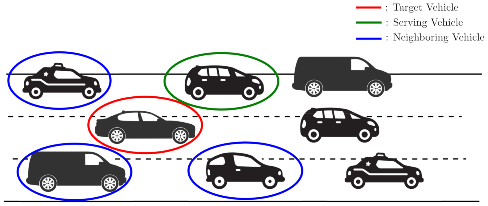
We assume our system model to be based on a WAVE system [3]. Figure 1 shows the system model composed of a group of vehicles. In the group, we consider vehicles of three types: serving vehicle, target vehicle, and neighboring vehicle. A serving vehicle acts as a WAVE system transmitter, and a target vehicle receives the signal from the serving vehicle. Neighboring vehicles generate interference to the link between the serving vehicle and the target vehicle. As far as the vehicle position is concerned, we consider that there should be a direct line of sight between the serving vehicle and the target vehicle. In this scenario, the vehicle communication between the serving vehicle and the target vehicle can be interfered with via wireless nodes from the neighboring vehicles [15]. Hence, the signal-to-interference and noise ratio (SINR) should be considered.
Although scenarios of multiple neighboring vehicles are possible, the complexity of wireless communication within heavy traffic is significant in the multiple vehicles cases. In this sector, we start on the single antenna port for transmit and transmit antenna diversity for simplicity before explaining the case of multiple antenna ports.
2.1.1. Single Transmit Antenna Port
In the single transmit antenna port, the received signal with two receiver antennas is defined as follows:
where is the transmit signal from the serving vehicle s and is the interference signal from the neighboring vehicle i. is the channel between the j-th receiver antenna of the vehicle s and is the channel between the j-th receiver antenna of the vehicle i. is additive white Gaussian noise (AWGN) of the j-th receiver antenna and is the total number of neighboring interference vehicles. The receiver can combine the received signals using the maximum ratio combining (MRC) [16] as follows:
where and is the sum of the neighboring vehicle interferences and AWGN.
2.1.2. Transmit Diversity with Multiple Antenna Ports
When we perform the transmit diversity [17] with two antenna ports in the serving vehicle, the received signals with two antennas can be expressed as follows:
where k is a time index. is the channel between the j-th receiver antenna and the l-th transmitter antenna of the serving vehicle s and is the channel between the j-th receiver antenna and the l-th transmitter antenna of the neighboring vehicle i. The receiver combines the signals from two antennas using the Hermitian of the channel matrix [17] as follows:
where and is the sum of the interference and AWGN of the m-th symbol.
2.2. WAVE Physical Layer
The physical layer of WAVE is defined in IEEE 802.11p standard [3]. IEEE 802.11p is the transformed form of the existing wireless local area network (WLAN) standard from IEEE 802.11. It operates in the frequency band of 5.850–5.925 GHz with the partly overlaying industry, science, and medical (ISM) band of the conventional WLAN standard. It also uses the 10 MHz bandwidth for a channel with OFDM modulation. Given that channel bandwidth, the range of data rate supported is 3–27 Mbps with the various modulation schemes, including BPSK, QPSK, 16QAM, etc. The OFDM signal comprises 64 subcarriers with 48 data, four pilots, and 12 direct currents (DC). In this paper, we consider the 6 Mbps data rate for simulation. Table 1 shows the parameters of the OFDM signal defined in IEEE 802.11p standard [3].
Table 2 shows a transmission mode of an OFDM signal by the data rate [3]. Note that each modulation and coding bit type depends on the data rate. In summary, the IEEE 802.11p standard has a narrow-band transmission spectrum as compared to the conventional wireless LAN standard and is defined to transmit the maximum transmission power of 44.8 dBm [3].
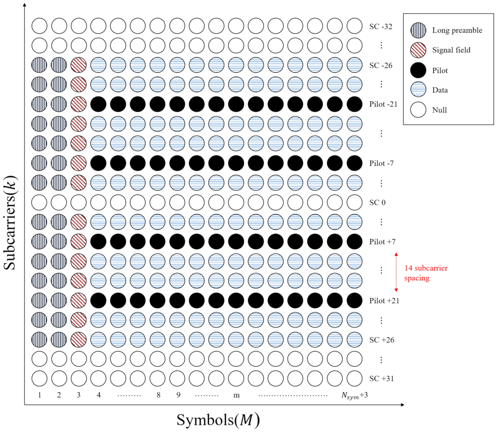
IEEE 802.11p standard also applied pilot arrangements with block and comb types as shown in Figure 2. At the first two OFDM symbols, block pilots are located across all subcarriers, and the OFDM system allocates comb pliots at subcarrier channel −21, −7, 7, and 21. The rest of the OFDM system contains data for transmission.
3. Interference Rejection Combining Scheme
In this section, we explain the details of our proposed scheme with interference rejection algorithms using minimum mean square error (MMSE) since we covered the system model of our work and the brief overview of WAVE systems.
3.1. WAVE Receiver Structure with IRC
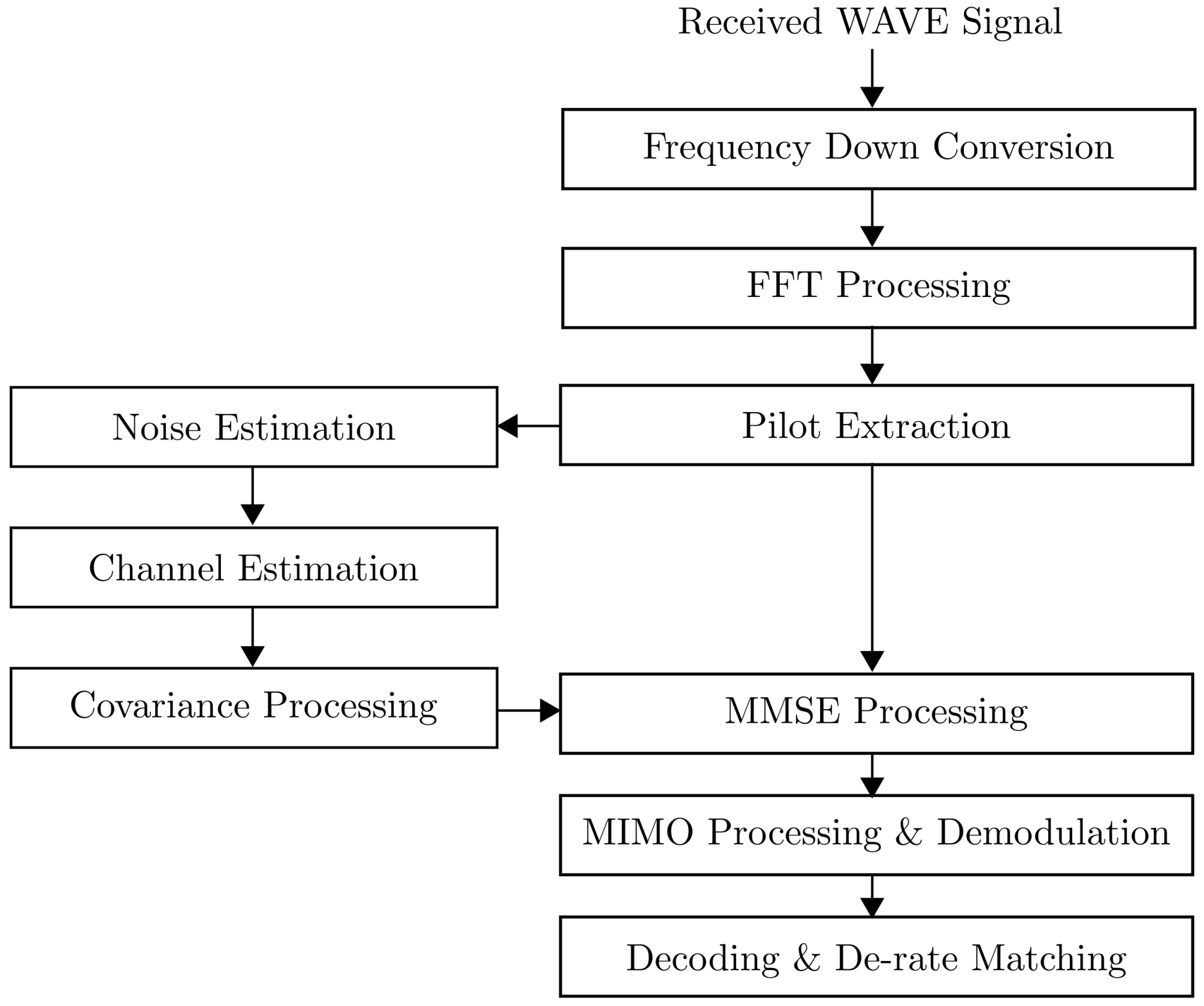
In this subsection, a receiver structure is presented based on the WAVE system [3]. Figure 3 shows the IRCt-based receiver structure. In this figure, IRC processing operates with the modules of pilot extraction, noise estimation, channel estimation, covariance, and MMSE processing. After fast Fourier transform (FFT) processing, the receiver estimates noise and channel responses from the received signal, and it also calculates the covariance of the interference for MMSE processing. The IRC scheme can mitigate the interference from neighboring vehicles using the covariance and MMSE processing.
In Figure 3, after the MMSE processing, the signal is demodulated in a MIMO processing and demodulation and decoded in a decoding and de-rate matching. The performance of the interference rejection scheme is highly dependent on the accuracy of the channel estimation. In this paper, we consider the assumption that the channel between serving and target vehicles is perfectly estimated so that the receiver performance is not affected by the channel estimation.
3.2. The Interference Rejection Combining Algorithm
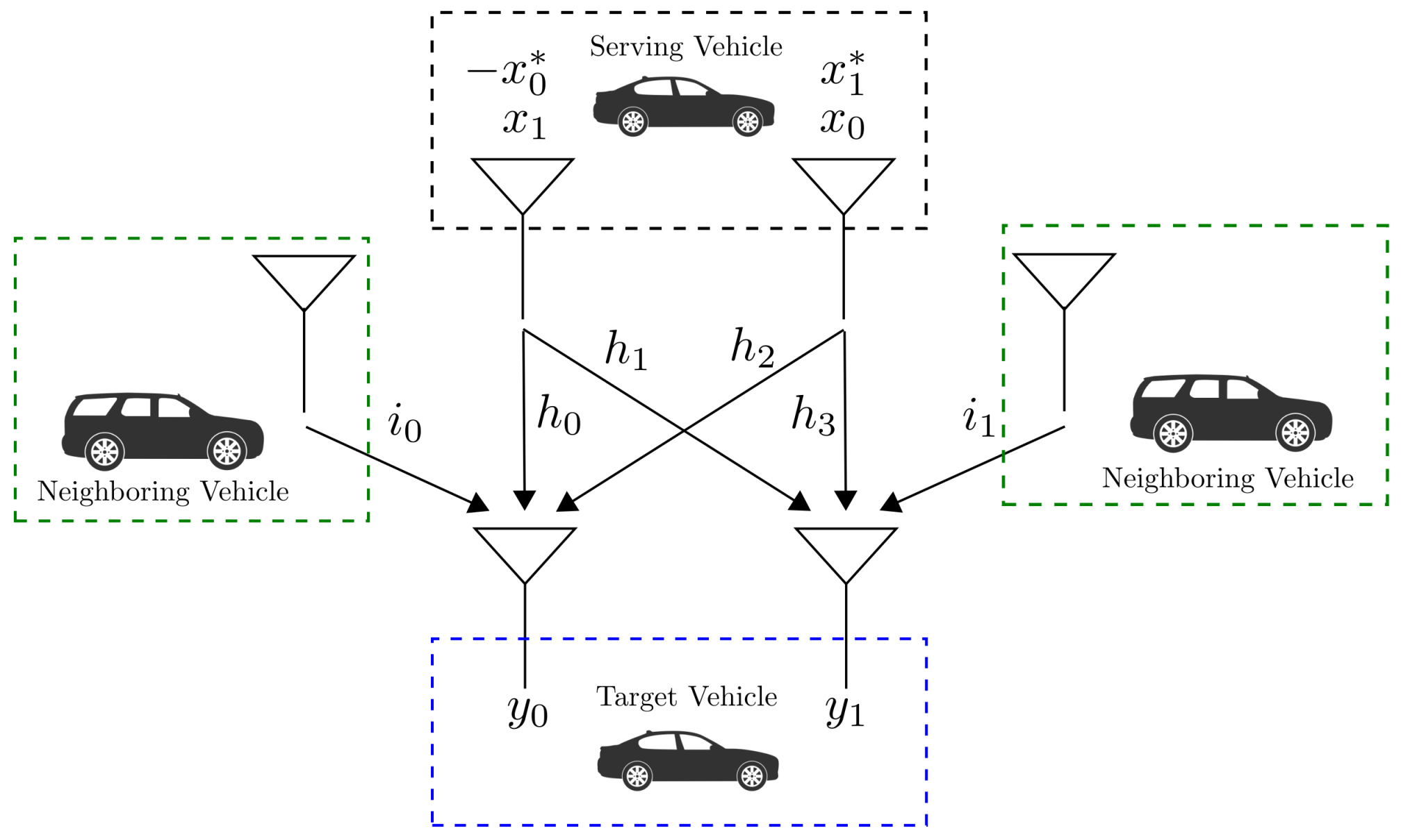
In this subsection, we present an interference rejection scheme to reduce the neighboring vehicle interferences with two receiver antennas. For the details of this scheme, we assume that the neighboring vehicle only uses single-antenna port in transmit mode. Figure 4 shows a system model for interference cancellation with a multiple-input multiple-output (MIMO) configuration.
In Figure 4, the received signal of the zero-th and the first receiver antennas can be expressed as follows:
where x is the data signal in the serving vehicle s and is the neighboring interference of the j-th receiver antenna; (5) can be simplified as follows:
The MMSE filter can be expressed as follows [20,21]:
where is a Hermitian operation and C is a covariance matrix expressed as follows:
where is an expectation operation.
It is highly complex to calculate the exact covariance matrix C. For computation, the covariance matrix C uses the estimated channel response H and pilot signals from the transmit signals as follows:
(9) can be possible only when x is the pilot signal. As shown in Figure 2, the average of the calculated covariance is obtained in 14 OFDM systems. After obtaining the covariance, its average is determined as the representative covariance of the each 14 OFDM symbols.
It is assumed that noise is sufficiently small compare with the interference; then (8) can be approximated as follows:
The signal component defined as from in (7) is as follows:
and the interference component from in (7) is the following:
In (11) and (12), we observe the perfect symbol recovery while presenting an interference. These results demonstrate that using interference rejection techniques can be effective to minimize the impact of the interference signal, given the assumption that we can perform the perfect channel estimation.
4. Performance Results
4.1. Test Environment Setup and Description
Since our interference rejection scheme as shown in Section 3 assumes to be operated on the traffic road environment with adjacent vehicles, we have to be aware that the performance evaluation must follow the specification of WAVE standards. The performance also has to be analyzed given the conditions of the vehicle speed and interference signal power. In this section, we present the simulation results with our proposed interference rejection scheme using the MMSE filter. A WAVE simulator is designed based on the WAVE standard [3] to evaluate the proposed interference cancellation receiver’s performance in a realistic environment. In the simulator, we considered the highway condition for fading channels, and no altitude matter was present on the data transmission. Since the vehicle is present with various interference signals from the neighboring vehicles, the WAVE simulator applied QPSK modulation and low-rate convolutional code. A finite impulse response (FIR) low pass filter in the frequency domain optimizes the component channel estimation. We applied two receiver antennas and two antenna ports for the MMSE filter. For the details of the parameters used in the data link simulator, Table 3 shows all necessary information.
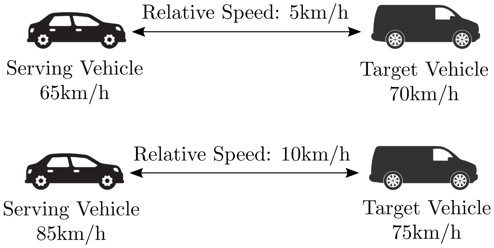
Note also that, in all performance results, we define the vehicle speed as the relative speed between the serving vehicle and the target vehicle shown in Figure 5 for the realistic road conditions during the operation. For instance, when each speed of the serving vehicle and the target vehicle is 65 km/h and 70 km/h, we calculate the relative speed as 5 km/h. In serving vehicles with 85 km/h and the target vehicle with 75 km/h, the relative speed must be 10 km/h. In this relative speed scenario, we assume that the neighboring vehicles perform the same relative speed as the target vehicle. In addition, we measure the vehicle speed up to 25 km/h to consider the realistic situation and experimental significance observed in [22].
4.2. Experimental Results
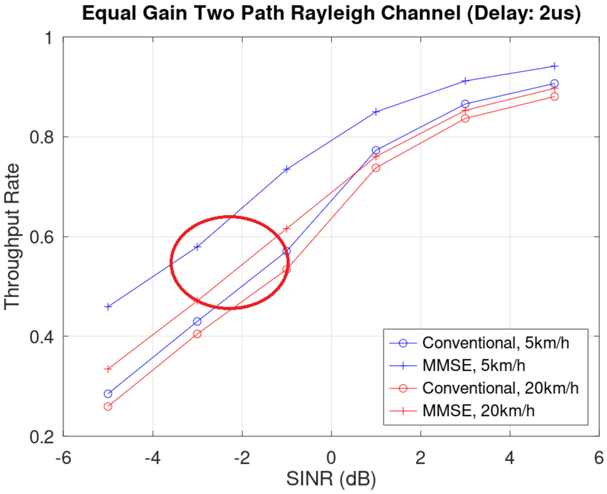
In the simulation, we present the performance results given the following channel conditions: equal gain Rayleigh channel with (1) 2 us delay and (2) 5 us delay. To analyze the throughput of the downlink in an equal-gain two-paths Rayleigh fading channel with 2 us delay between the two paths, Figure 6 compares the throughput performances of the receivers considered in this paper. For throughput = 0.5, the receivers with interference cancellation could achieve about 2.0 dB and 1.0 dB performance gain, compared with the conventional receivers with 5 km/h and 20 km/h, respectively. In the throughput perspective, the throughput gain is 0.164 and 0.081 when 5 km/h and 20 km/h with SINR = −1.
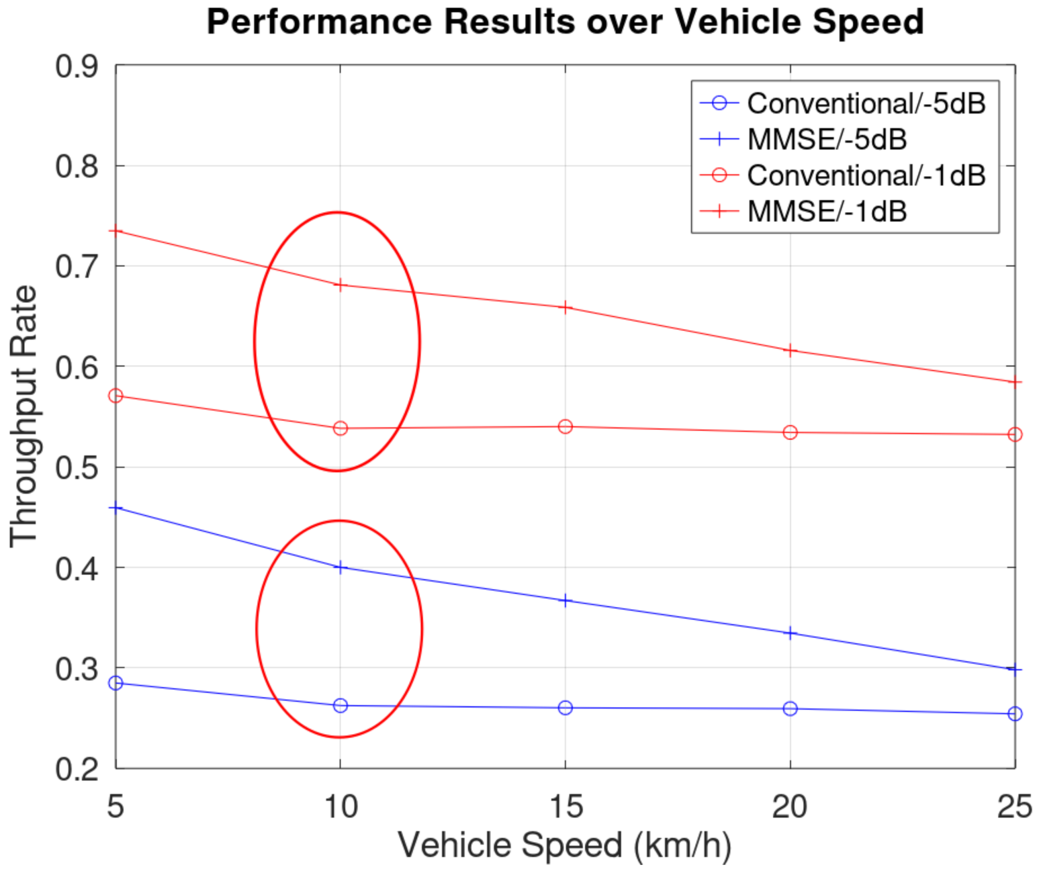
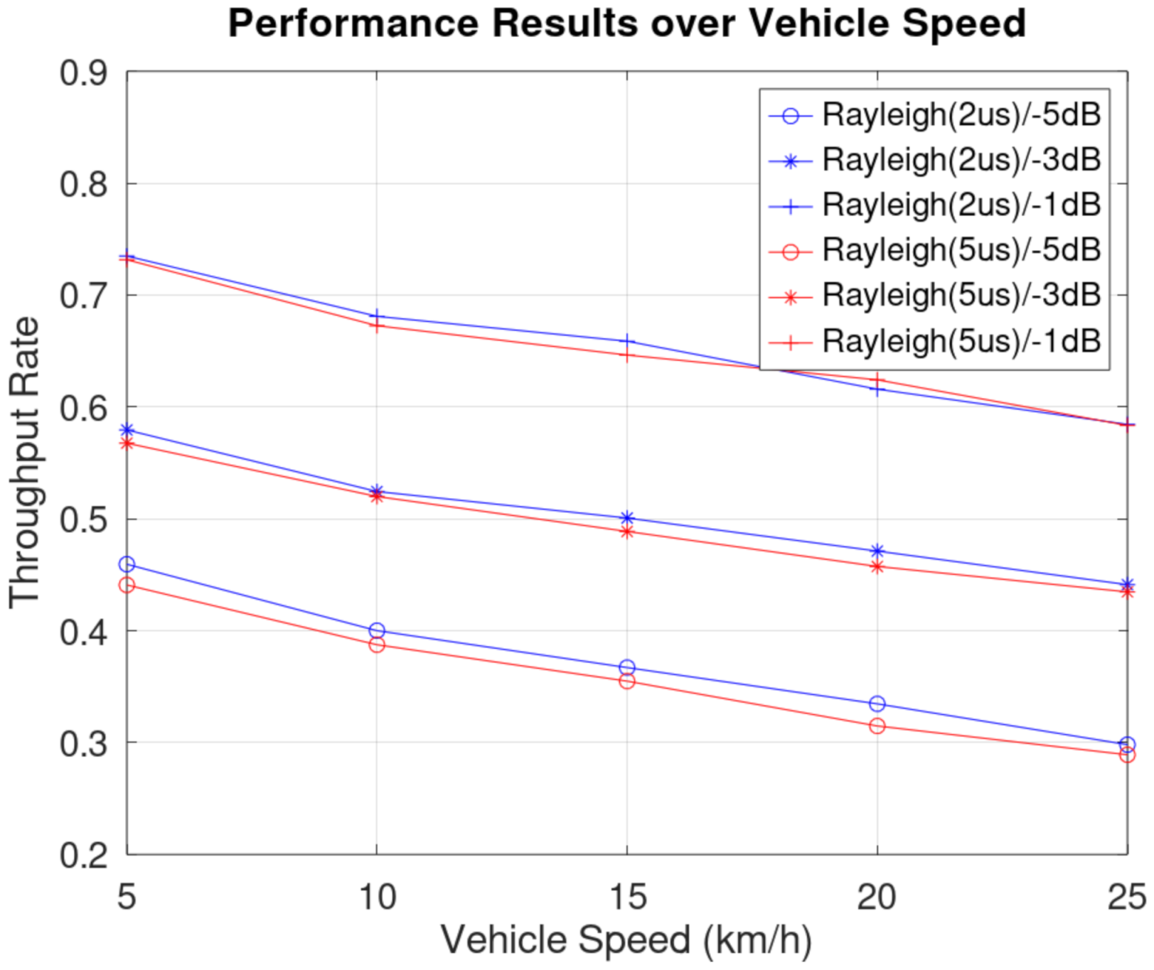
Figure 7 shows the throughput performances of the receivers over vehicle speeds. When the vehicle speed increased, the performance with interference cancellation still outperformed the conventional receivers, but performance gain reduced steadily. In the red circle, we observed that the performance gains of MMSE at 10 km/h in −5 dB and −1 dB SINRs were 0.137 and 0.142, respectively. This result indicated that the SINR is not a significant factor for the performance gap of interference cancellation.
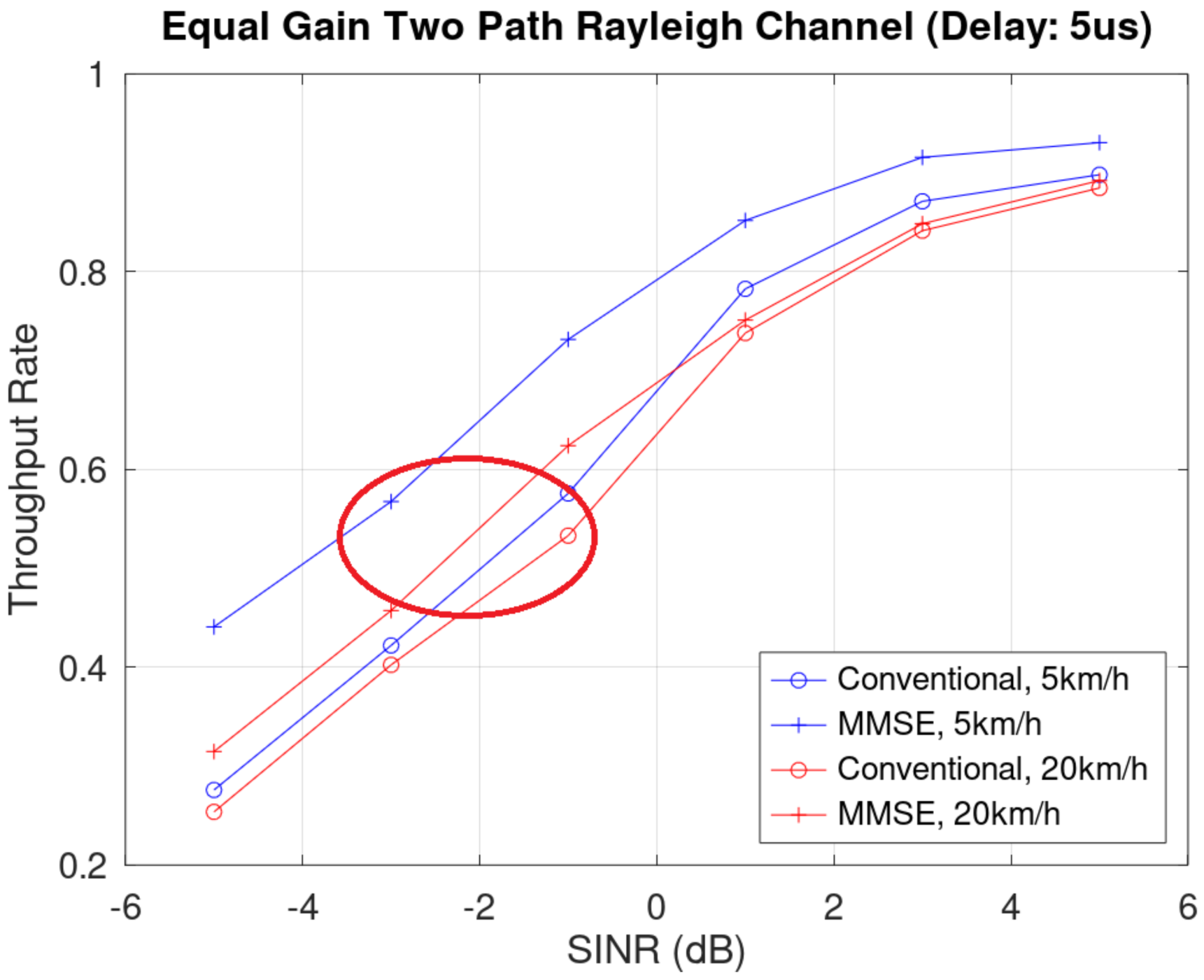
Figure 8 shows the throughput of the downlink in the Rayleigh channel with a 5 us delay. In Figure 8, we compare the throughputs of the receivers considered in this paper. For throughput = 0.4, compared with the conventional receiver, the receivers with interference cancellation achieved about 2.0 dB and 0.5 dB performance gains with 5 km/h and 20 km/h, respectively. For throughput gain, our scheme achieved 0.1558 and 0.091 when 5 km/h and 20 km/h with SINR = −1. Note that the performance improvement of MMSE was well-present in low SINR.
As compared to Figure 7 and Figure 9 provided the comparison between the performance of different fading channels in various SINR. In this result, we confirmed that the slight delay of Rayleigh fading shows performance degradation in low SINRs. However, we also observed that when SINR is −3 dB, the performance gap becomes narrower than in −5 dB. In SINR with −1 dB, the performance gap is barely visible. This observation explained that when the SINR becomes high, the fading channel condition becomes insignificant for the performance gain.
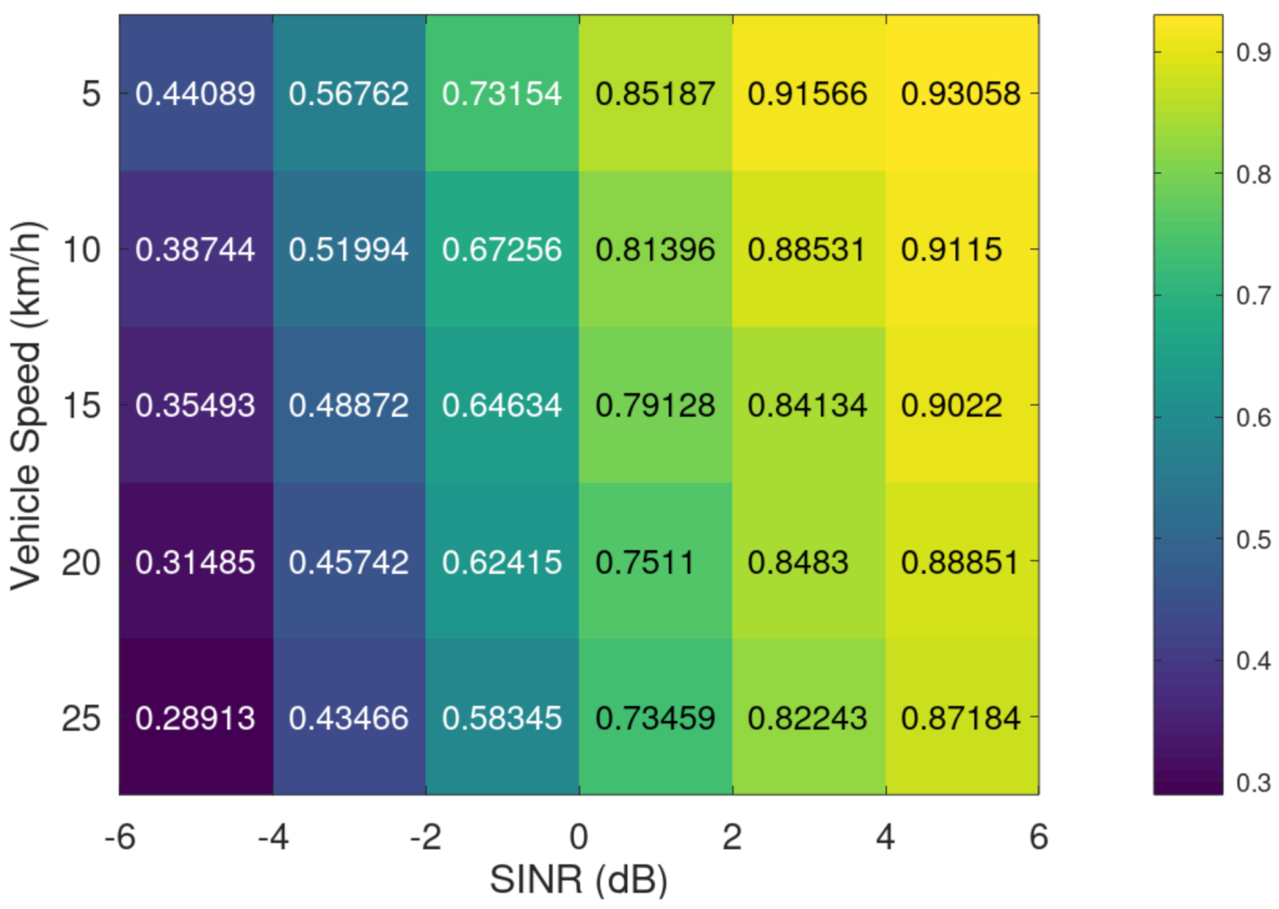
Extending our experiment results to the comprehensive view of throughput rate performance, we produced the colormap of the throughput rate over vehicle speeds to visualize the performance patterns as shown in Figure 10 and Figure 11. In Figure 10 with the Rayleigh channel in a delay of 2 us, we observed that when the SINR is low, the vehicle speeds become the significant factor for performance degradation by comparing the throughput rate at 5 km/h and 25 km/h at SINR= −5 dB. However, the performance gap in the high SINR is not as high as that of the low SINR. Note that the performance gap at 5 dB is 0.05881 as compared to 0.1612 at −5 dB. In the 5 us delay case from Figure 11, its performance pattern follows that shown in Figure 10. Note that the low SINR results in Figure 11 are inferior to the results in Figure 10, whereas the high SINR results show no significant performance loss.
In the results section, we showed the performance gain of IRC algorithms, and the gain depends on the various factors, including SINR, vehicle speed, and fading channel condition. In particular, the channel conditions must be well studied as examples of colormap, such as Figure 10 and Figure 11 for the WAVE system implementation, since the fading channel situation changes depending on the road, traffic condition, and location.
5. Conclusions
In this paper, we proposed the interference rejection scheme with the MMSE filter for WAVE systems. In the interference rejection scheme, the MMSE approach can effectively suppress the interference and recover the symbol to improve throughput rates of the systems while both the transmitter and receiver (e.g., serving vehicle and target vehicle) are in the non-stationary condition. Our performance results showed that our proposed scheme can achieve a substantial gain in low and high vehicle speed cases as compared to the WAVE system without MMSE. In particular, the scheme operated strongly at the low SINR case. In the vehicle speed case, we observed that the performance gain becomes inversely proportional to the vehicle speed. We also showed the performance map of our scheme to observe the performance pattern over vehicle speed and SINR.
While we were able to produce the performance results of our proposed scheme, we assumed that the neighboring vehicle performs at the same relative speed as the target vehicle. For the further research, we have to investigate and research the improvement of our IRC scheme to achieve the performance, given different relative speed cases of each vehicle. In addition, we only considered the limited antenna port cases in our paper. Since multi-array antenna beamforming is common in modern communication systems, we need to analyze the possibility of using those multiple antenna-based techniques. In future work, the fading channel-based performance fluctuation may become a potential issue and, using the iterative scheme to find the optimal parameters of each antenna beam direction, we may find the best setting in the WAVE system to provide sustainable throughput performance.
Author Contributions
Conceptualization, Y.-j.P. and S.-m.S.; methodology, Y.-j.P.; software, Y.-j.P. and J.-y.K.; validation, Y.-j.P. and J.-y.K.; investigation, Y.-j.P., J.-y.K. and J.-i.J.; resources, Y.-j.P., S.-m.S. and J.-i.J.; data curation, Y.-j.P., S.-m.S. and J.-y.K.; writing, Y.-j.P., S.-m.S., J.-y.K. and J.-i.J.; visualization, Y.-j.P. and J.-y.K.; supervision, Y.-j.P., J.-y.K. and J.-i.J.; project administration, Y.-j.P., J.-y.K. and J.-i.J. All authors have read and agreed to the published version of the manuscript.
Funding
This work was supported by Institute of Information & communications Technology Planning & Evaluation (IITP) grant funded by the Korea government(MSIT) (No. 2019-0-00148, Development of Dual Convergence Security Technology on Touch Control System using Smartphone for the control of Autonomous Driving Vehicle).
Conflicts of Interest
The authors declare no conflict of interest.
Abbreviations
The following abbreviations are used in this manuscript:
| IRC | Interference Rejection Combining |
| WAVE | Wireless Access in Vehicular Environments |
| MMSE | Minimum Mean Square Error |
| SINR | Signal-to-Interference and Noise Ratio |
| SNR | Signal-to-Noise Ratio |
| OFDM | Orthogonal Frequency Division Multiplexing |
| MIMO | Multiple Input Multiple Output |
| FFT | Fast Fourier Transform |
| AWGN | Additive White Gaussian Noise |
| BPSK | Binary Phase Shift Keying |
| QPSK | Quadrature Phase Shift Keying |
| QAM | Quadrature Amplitude Modulation |
| LAN | Local Area Network |
References
- Bai, F.; Krishnan, H. Reliability analysis of DSRC wireless communication for vehicle safety applications. In Proceedings of the 2006 IEEE Intelligent Transportation Systems Conference, Toronto, ON, Canada, 17–20 September 2006; pp. 355–362. [Google Scholar]
- Seo, H.S.; Jung, J.S.; Lee, S.S. Network performance analysis and manuever model for overtaking assistant service using wave. Int. J. Automot. Technol. 2014, 15, 57–64. [Google Scholar] [CrossRef]
- IEEE Computer Society. IEEE Std 802.11p, IEEE standard for information technology-telecommunications and information exchange between systems-local and metropolitan area networks-specific requirements Part 11: Wireless LAN Medium Access Control (MAC) and Physical Layer (PHY) Specifications Am; Draft Standard Version; IEEE Computer Society: Washington, DC, USA, 2010. [Google Scholar]
- Jiang, D.; Delgrossi, L. IEEE 802.11p: Towards an International Standard for Wireless Access in Vehicular Environments. In Proceedings of the VTC Spring 2008—IEEE Vehicular Technology Conference, Marina Bay, Singapore, 11–14 May 2008; pp. 2036–2040. [Google Scholar]
- Choi, H.; Park, J.; Choi, W.; Oh, S. Vision-based fusion of robust lane tracking and forward vehicle detection in a real driving environment. Int. J. Automot. Technol. 2012, 13, 653–669. [Google Scholar] [CrossRef]
- Lee, B.; Kim, G. Robust detection of preceding vehicles in crowded traffic conditions. Int. J. Automot. Technol. 2012, 13, 671–678. [Google Scholar] [CrossRef]
- Seo, H.S.; Kim, B.C.; Park, B.S.; Lee, C.D.; Lee, S.S. Design and implementation of a UPNP-CAN gateway for automotive environments. Int. J. Automot. Technol. 2013, 14, 91–99. [Google Scholar] [CrossRef]
- Nekovee, M. Quantifying performance requirements of vehicle-to-vehicle communication protocols for rear-end collision avoidance. In Proceedings of the VTC Spring 2009—IEEE 69th Vehicular Technology Conference, Barcelona, Spain, 26–29 April 2009; pp. 1–5. [Google Scholar]
- Cho, W.; Han, K.-S.; Choi, H.K.; Oh, H.S. Realization of anti-collision application using V2V communication. In Proceedings of the 2009 IEEE Vehicular Networking Conference (VNC), Tokyo, Japan, 28–30 October 2009; pp. 1–5. [Google Scholar]
- Campolo, C.; Vinel, A.; Molinaro, A.; Koucheryavy, Y. Modeling broadcasting in IEEE 802.11 p/WAVE vehicular networks. IEEE Commun. Lett. 2010, 15, 199–201. [Google Scholar] [CrossRef] [Green Version]
- Srinivasan, S.; Renfors, M. Interference rejection combining for black-space cognitive radio communications. In International Conference on Cognitive Radio Oriented Wireless Networks; Springer: Berlin/Heidelberg, Germany, 2018; pp. 200–210. [Google Scholar]
- Zhang, X.; Yang, L.; Ding, Z.; Song, J.; Zhai, Y.; Zhang, D. Sparse vector coding-based multi-carrier NOMA for in-home health networks. IEEE J. Sel. Areas Commun. 2020, 39, 325–337. [Google Scholar] [CrossRef]
- Usman, M.R.; Usman, M.A.; Shin, S.Y.; Satrya, G.B.; Naqvi, R.A.; Martini, M.G.; Politis, C. Walsh–Hadamard transform based non–orthogonal multiple access (NOMA) and interference rejection combining in next-generation HetNets. Mathematics 2021, 9, 348. [Google Scholar] [CrossRef]
- Jaffry, S.; Hussain, R.; Gui, X.; Hasan, S.F. A Comprehensive Survey on Moving Networks. IEEE Commun. Surv. Tutor. 2020. [Google Scholar] [CrossRef]
- Schmidt-Eisenlohr, F. Interference in Vehicle-to-Vehicle Communication Networks; Karlsruhe Institut für Technologie (KIT) Scientific Publishing: Karlsruhe, Germany, 2010. [Google Scholar]
- Goldsmith, A. “Diversity” Wireless Communications; Cambridge University Press: Cambridge, UK, 2005; pp. 204–227. [Google Scholar]
- Alamouti, S.M. A simple transmit diversity technique for wireless communications. IEEE J. Select. Areas Comm. 1998, 16, 1451–1458. [Google Scholar] [CrossRef]
- IEEE P802.11p-2010: Part 11: Wireless LAN Medium Access Control (MAC) and Physical Layer (PHY) Specifications: Amendment 6: Wireless Access in Vehicular Environments, 15 July 2010. Available online: https://0-standards-ieee-org.brum.beds.ac.uk/standard/802_11p-2010.html (accessed on 9 August 2021).
- Choi, J.Y.; Jo, H.S.; Mun, C.; Yook, J.G. Preamble-based adaptive channel estimation for IEEE 802.11 p. Sensors 2019, 19, 2971. [Google Scholar] [CrossRef] [PubMed] [Green Version]
- Naguib, A.F.; Seshadri, N.; Calderbank, A.R. Applications of space-time block codes and interference suppression for high capacity and high data rate wireless systems. In Proceedings of the Conference Record of Thirty-Second Asilomar Conference on Signals, Systems and Computers (Cat. No.98CH36284), Pacific Grove, CA, USA, 1–4 November 1998; pp. 1803–1810. [Google Scholar]
- Li, Q.; Zhu, J.; Guo, X.; Georghiades, C.N. Efficient spatial covariance estimation for asynchronous co-channel interference suppression in MIMO OFDM systems. IEEE Trans. Wireless Commun. 2008, 7, 4849–4853. [Google Scholar] [CrossRef]
- Liu, S.; Xiang, W.; Punithan, M.X. An empirical study on performance of DSRC and LTE-4G for vehicular communications. In Proceedings of the 2018 IEEE 88th Vehicular Technology Conference (VTC-Fall), Chicago, IL, USA, 27–30 August 2018; pp. 1–5. [Google Scholar]
Figure 1.
System model with multiple vehicles.

Figure 2.
Preamble, signal field, pilot and data arrangement map for IEEE 802.11p [18,19]. Note that data and pilot started to fill in for transmission after third symbols.

Figure 3.
IRC-based WAVE receiver structure.

Figure 4.
Overall structure of MIMO (2 × 2) system model. Note that the neighboring vehicle on the left and right are identical and the same entity. We described one vehicle as two separate entities on the left and right sides to clarify the interference matters from the neighboring vehicle with a single antenna.

Figure 5.
Examples of the relative speed between serving vehicle and target vehicle. Note that the relative speed also impacts the neighboring vehicles.
Figure 5.
Examples of the relative speed between serving vehicle and target vehicle. Note that the relative speed also impacts the neighboring vehicles.

Figure 6.
Throughput rate in an equal-gain two-paths Rayleigh fading channel with 2 us delay.

Figure 7.
Throughput over vehicle speed, an equal-gain two-paths Rayleigh fading channel with 2 us delay.
Figure 7.
Throughput over vehicle speed, an equal-gain two-paths Rayleigh fading channel with 2 us delay.

Figure 8.
Throughput rate in an equal-gain two-paths Rayleigh fading channel with 5 us delay.

Figure 9.
Throughput rate over vehicle speeds in different equal-gain two-paths Rayleigh fading channels.
Figure 9.
Throughput rate over vehicle speeds in different equal-gain two-paths Rayleigh fading channels.

Figure 10.
Performance colormap over vehicle speed and SINR in an equal-gain two-paths Rayleigh fading channel with delay 2 us.
Figure 10.
Performance colormap over vehicle speed and SINR in an equal-gain two-paths Rayleigh fading channel with delay 2 us.

Figure 11.
Performance colormap over vehicle speed and SINR in an equal-gain two-paths Rayleigh fading channel with delay 5 us.
Figure 11.
Performance colormap over vehicle speed and SINR in an equal-gain two-paths Rayleigh fading channel with delay 5 us.


Table 1.
Properties of OFDM signal in IEEE 802.11p.
| Parameter | Value |
|---|---|
| Bandwidth | 10 MHz |
| FFT Size | 64 |
| Subcarrier Interval | 0.15625 MHz |
| Signal Bandwidth | 8.28 MHz |
| IFFT / FFT Interval | 6.4us |
| Guard Interval | 1.6us |
| Symbol Interval | 8.0(6.4 + 1.6) us |
Table 2.
Transmission mode of OFDM signal according to the data rate in IEEE 802.11p.
| Data Rate (Mbits/s) | Modulation | Coding Rate | Coded Bits per Subcarrier | Coded Bits per OFDM Symbol | Data Bits per OFDM Symbol |
|---|---|---|---|---|---|
| 3 | BPSK | 1/2 | 1 | 48 | 24 |
| 4.5 | BPSK | 3/4 | 1 | 48 | 36 |
| 6 | QPSK | 1/2 | 2 | 96 | 48 |
| 9 | QPSK | 3/4 | 2 | 96 | 72 |
| 12 | 16-QAM | 1/2 | 4 | 192 | 96 |
| 18 | 16-QAM | 3/4 | 4 | 192 | 144 |
| 24 | 64-QAM | 2/3 | 6 | 288 | 192 |
| 27 | 64-QAM | 3/4 | 6 | 288 | 216 |
Table 3.
Simulation parameters.
| Parameter | Value |
|---|---|
| Data Rate (Mbits/s) | 6 |
| Error Correction Coding | Convolutional Code |
| # of antenna | 2 × 2 |
| Channel | An equal-gain two-paths Rayleigh fading channel (Delay between the two-paths: 2 us and 5 us) |
| Signal-to-Noise Ratio | 20 dB |
| Vehicle Speed | 5 km/h∼25 km/h |
Publisher’s Note: MDPI stays neutral with regard to jurisdictional claims in published maps and institutional affiliations. |
© 2021 by the authors. Licensee MDPI, Basel, Switzerland. This article is an open access article distributed under the terms and conditions of the Creative Commons Attribution (CC BY) license (https://creativecommons.org/licenses/by/4.0/).
Share and Cite
MDPI and ACS Style
Park, Y.-j.; Sung, S.-m.; Kim, J.-y.; Jung, J.-i. Interference Rejection Combining Approach in Vehicle Communication Systems for Throughput Enhancement. Electronics 2021, 10, 1922. https://0-doi-org.brum.beds.ac.uk/10.3390/electronics10161922
AMA Style
Park Y-j, Sung S-m, Kim J-y, Jung J-i. Interference Rejection Combining Approach in Vehicle Communication Systems for Throughput Enhancement. Electronics. 2021; 10(16):1922. https://0-doi-org.brum.beds.ac.uk/10.3390/electronics10161922
Chicago/Turabian StylePark, Yun-joong, Sang-mo Sung, Joon-young Kim, and Jae-il Jung. 2021. "Interference Rejection Combining Approach in Vehicle Communication Systems for Throughput Enhancement" Electronics 10, no. 16: 1922. https://0-doi-org.brum.beds.ac.uk/10.3390/electronics10161922
Note that from the first issue of 2016, this journal uses article numbers instead of page numbers. See further details here.