Step-Up Partial Power DC-DC Converters for Two-Stage PV Systems with Interleaved Current Performance


Electronics Engineering Department, Universidad Tecnica Federico Santa Maria, Valparaiso 2390123, Chile
*
Author to whom correspondence should be addressed.
†
These authors contributed equally to this work.
Energies 2018, 11(2), 357; https://0-doi-org.brum.beds.ac.uk/10.3390/en11020357
Submission received: 1 December 2017
/
Revised: 25 January 2018
/
Accepted: 30 January 2018
/
Published: 3 February 2018
(This article belongs to the Special Issue Emerging Power Electronics Technologies for Power Systems and Machine Drives)
Abstract
:This work presents a partial power converter allowing us to obtain, with a single DC-DC converter, the same feature as the classical interleaved operation of two converters. More precisely, the proposed topology performs similarly as the input-parallel output-series (IPOS) configuration reducing the current ripple at the input of the system and dividing the individual converters power rating, compared to a single converter. The proposed topology consists of a partial DC-DC converter processing only a fraction of the total power, thus allowing high efficiency. Experimental results are provided to validate the proposed converter topology with a Flyback-based 100 W test bench with a transformer turns ratio . Experimental results show high performances reducing the input current ripple around , further increasing the conversion efficiency.
1. Introduction
Interleaved converters are widely used among power electronic applications. Such configurations can be adopted for different reasons in view of the features and benefits of the interleaved scheme. The two main advantages are:
- Distribution of the power among several converters, thus allowing us to reduce the power rating of the individual converters.
- Ripple reduction at the input and/or output of the converter when phase shifted carriers are used in the modulation, thus allowing reduction in the filters size.
Improvement in reliability is another among several advantages of interleaved configurations, making it possible to operate under failure of an individual converter thanks to the redundancy [1]. An additional advantage is the possibility of obtaining higher conversion ratio if input-parallel output-series (IPOS) or input-series output-parallel (ISOP) schemes are adopted. On the other hand, the main drawback is the increase in number of the power converters required in interleaved configurations.
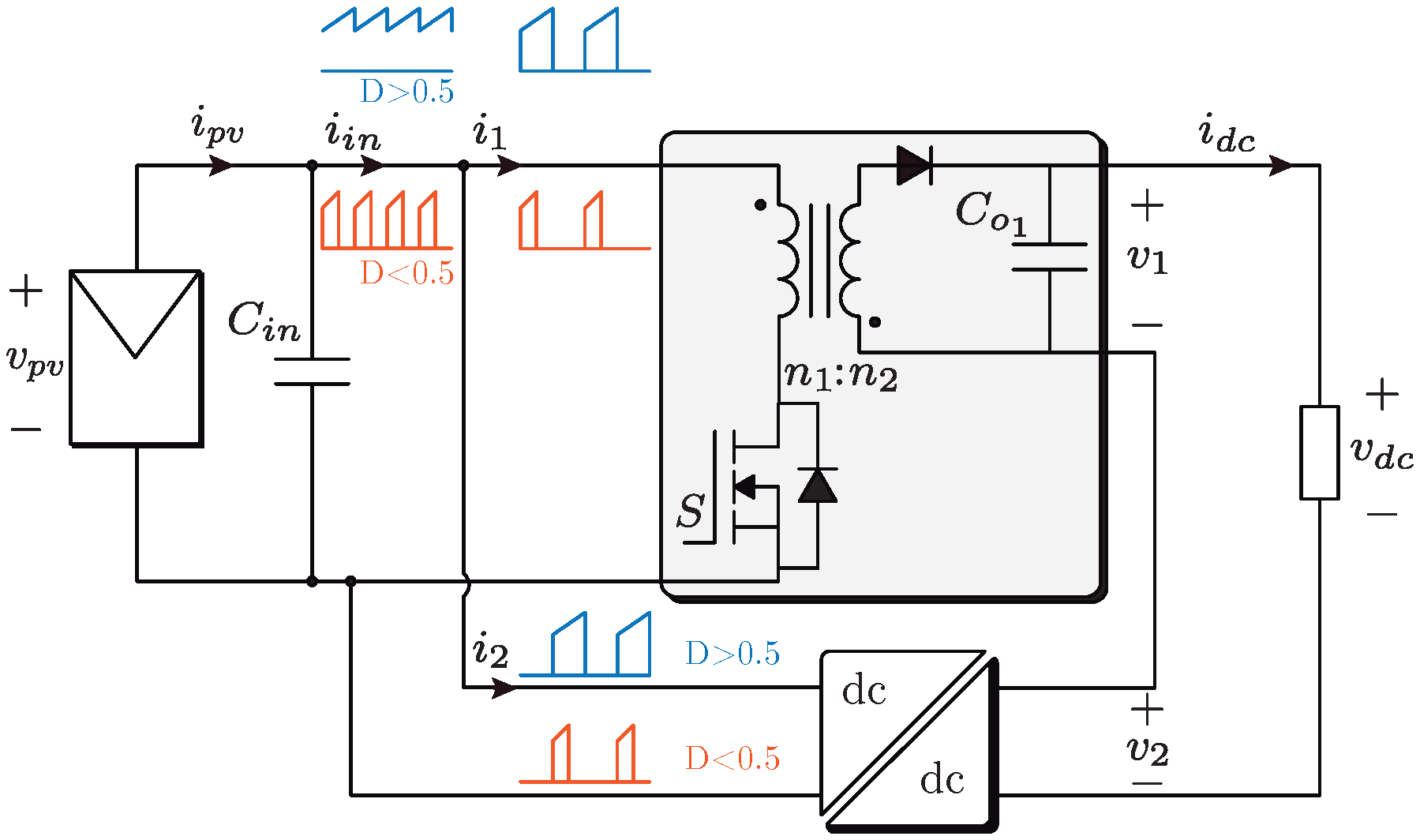
In this work, a partial power DC-DC converter is proposed. It performs a step-up operation, and it is based on a Flyback topology with a transformer turns ratio in order to improve the input current performance. However, the turns ratio can vary when higher voltage gains are required but it could reduce the performance of the input current, leading into higher current ripples. Compared to a classical DC-DC converter, the proposed topology performs similarly to the IPOS configuration, reducing the current ripple at the input of the system and reducing the converter power rating. The traditional IPOS interleaved converter scheme and main waveforms are given in Figure 1, for the case of Flyback topology. This specific topology has been used in several application such as two-stage photovoltaic (PV) inverters [2,3].
2. Proposed Topology
2.1. Partial Power Converters
The Partial Power Converter (PPC) concept has been around in other applications such as wind turbines, by using a doubly fed induction generator with an indirect four quadrant AC-DC-AC converter connected between the rotor windings [4] and the grid, and an additional direct grid connection to the stator. In this case the converter is only rated at 30% of the wind turbine power; yet it provides enough control range to perform variable speed operation and maximum power point tracking. The PPC concept oriented to PV systems was introduced in [5], in order to reduce the power losses inherent in two-stage configurations. The operation principle is based on the power biasing, establishing a series path between the input and output side. In essence the operating principle is to connect a series voltage between the PV system and the DC-link of the inverter. Since this voltage is usually smaller than the other two, it will process less power. It has been shown that the PPC concept improves the system efficiency compared to a classical full power converter. The PPC can also significantly reduce the converter size and power loss [6]. In this work the efficiency achieved working with a rated power lower than is around . For those reasons, the PPC concept has been used for various applications such as photovoltaic module integrated converter [7], PV powered electric aircraft [8], and distributed architectures. In those applications, the achieved efficiency is higher than and respectively, when the power processed is lower than of the rated power. Other applications based on the same series connection are found in [9,10], where a 25 kW prototype was developed. The topology used for the experiment were four Full-bridge converters connected in series, designed to handle 30.7% of the rated power and achieving an efficiency around 96% working at 33 kHz. In [11,12,13,14], the focus is on the use of PPC for microinverter configurations. They present an improvement in the conversion efficiency, which is commonly a problem in microinverters due to the high voltage elevation required for the grid-connection. In those evaluation cases, the conversion efficiency is around when the power processed by the converter is lower than of the rated power. It concludes that the conversion efficiency increases by reducing the power processed by the converter.
2.2. Topology Description
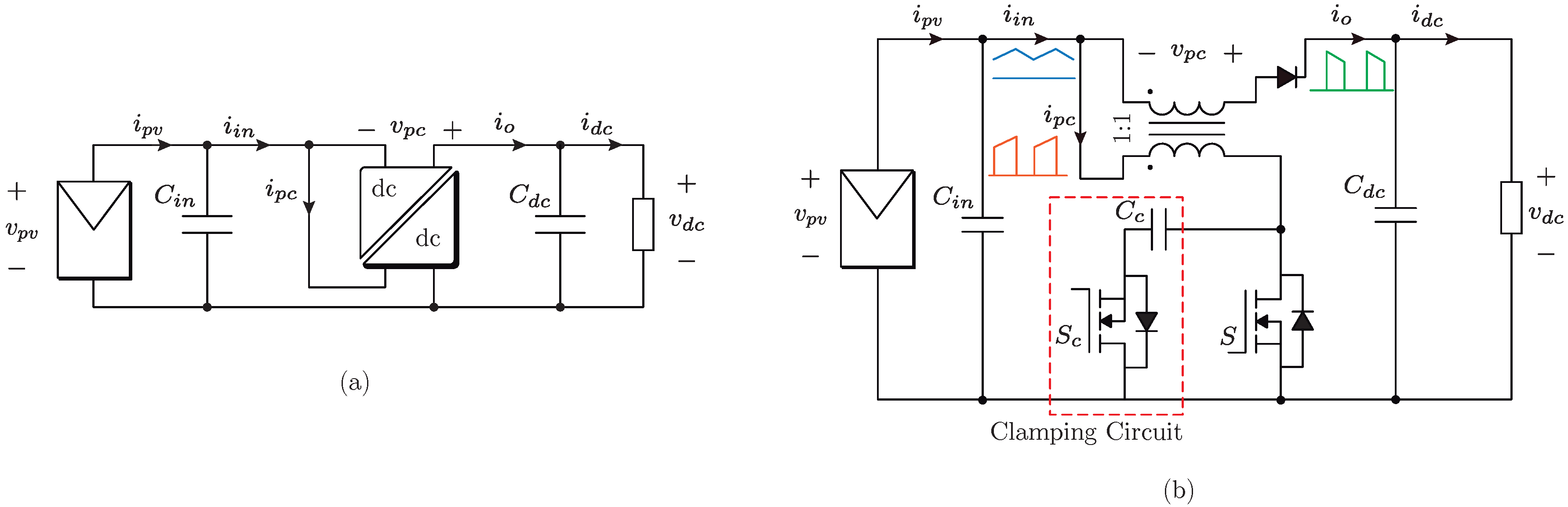
The proposed partial power converter topology is depicted in Figure 2a. It consists of an isolated DC-DC converter connected following the PPC concept, so that the output of the system is the sum of the PV voltage and the converter output . It should be noticed that even if the converter used has a HF transformer, due to the PPC connection the resulting conversion PV system does not provide galvanic isolation. This might be seen as a drawback, but considering that the power rating of the converter will be much lower than the total power, this is not a significant issue. Furthermore, the grounding of the PV system can be achieved by proper selection of the inverter stage and modulation, as with traditional transformer-less PV inverters [15].
In Figure 2b, the proposed converter is represented as a Flyback converter with clamping circuit such as it has been validated in Experimental section. In Figure 2b the current typical waveforms are also shown.
In general terms, no matter the PPC configuration nor the isolated DC-DC topology, the voltage gain of the DC-stage is expressed as:
Moreover, considering that the input and output capacitors losses are neglected, the DC-stage conversion efficiency is expressed as:
In general terms, the partial power ratio is defined as:
And, in order to define the operation region of the Step-Up PPC, the partial power ratio is calculated as:
In order to express the in terms of the DC-stage efficiency and voltage gain, (3) is included in (7) and the partial power ratio is finally defined as:
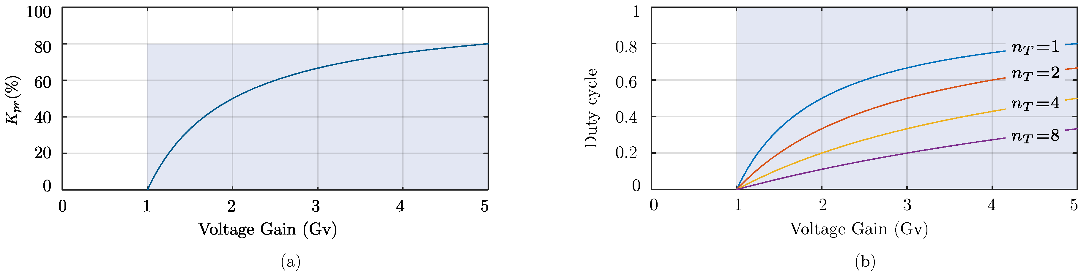
Considering that the DC-stage is highly efficiency , the partial power ratio varies depending on the voltage gain as depicted in the Figure 3a. Where the shadowed area represents the region of partial power operation.
Analysis of Topology
Commercial DC-DC converters for PV applications are based on traditional topologies. Among the criteria for the topology selection are the complexity of the structure, the control technique, reliability and efficiency [15]. The operation of the PPC in terms of duty cycle varies depending on the isolated DC-DC topology. In this section the traditional Flyback converter is chosen not only because its simple structure and high applicability in the PV industry [16,17]. But also because its operation features as will be analyzed in this section. Nevertheless, the same analysis can be made for different isolated DC-DC topologies.
This analysis is based on the operation range, which means that the converter must have the ability to elevate the voltage and work as a PPC within the duty cycle range d = [0–1]. Moreover, is also analyzed the importance and dependence of the transformer turns ratio in the operation range.
Working with a Flyback topology for the PPC configuration, and connecting as depicted in Figure 2b, the DC-DC converter voltage gain is calculated as:
Applying (4), the equation can be expressed as:
Rearranging and simplifying the expression, also considering that . Then the global voltage gain can be expressed as:
The voltage gain (11) depends on the duty cycle d, which is limited to [0–1], and the transformer turns ratio . The operation range is depicted in Figure 3b, where the shadowed area represents the region of partial power operation.
From this picture it is possible to see that using a Flyback topology for the PPC configuration, the converter operation is not limited by the voltage gain, but the transformer turns ratio. For example, considering a small voltage gain (e.g, ), and a turns ratio , the duty cycle range is limited to d = [0–0.11]. It means that a high resolution in the control platform is needed to compensate the small variations, which is translated to a more expensive control design. Instead, with a transformer turns ratio , the duty cycle range increases to d = [0–0.5] for the same application. The same analysis can be applied for higher voltage gains, where the best resolution is achieved by using a transformer with greater turns ratio.
At this point it is worth enhancing the advantages of the presented topology. The waveforms in Figure 2b show one of the advantages respect to the traditional IPOS configuration. Indeed, the input current of the proposed topology is the sum of the current and . As those currents are complementary, the resulting current will be continuous for any duty cycle if the converter operates under continuous conduction mode (CCM). Moreover, with the transformer turn ratio both, the current and have the same peak value, which leads in a continuous input current . On the other side, in the case of the traditional IPOS configuration realized with Flyback converters, the input current shown in Figure 1 is discontinuous for duty cycles lower than .
3. Experimental Results
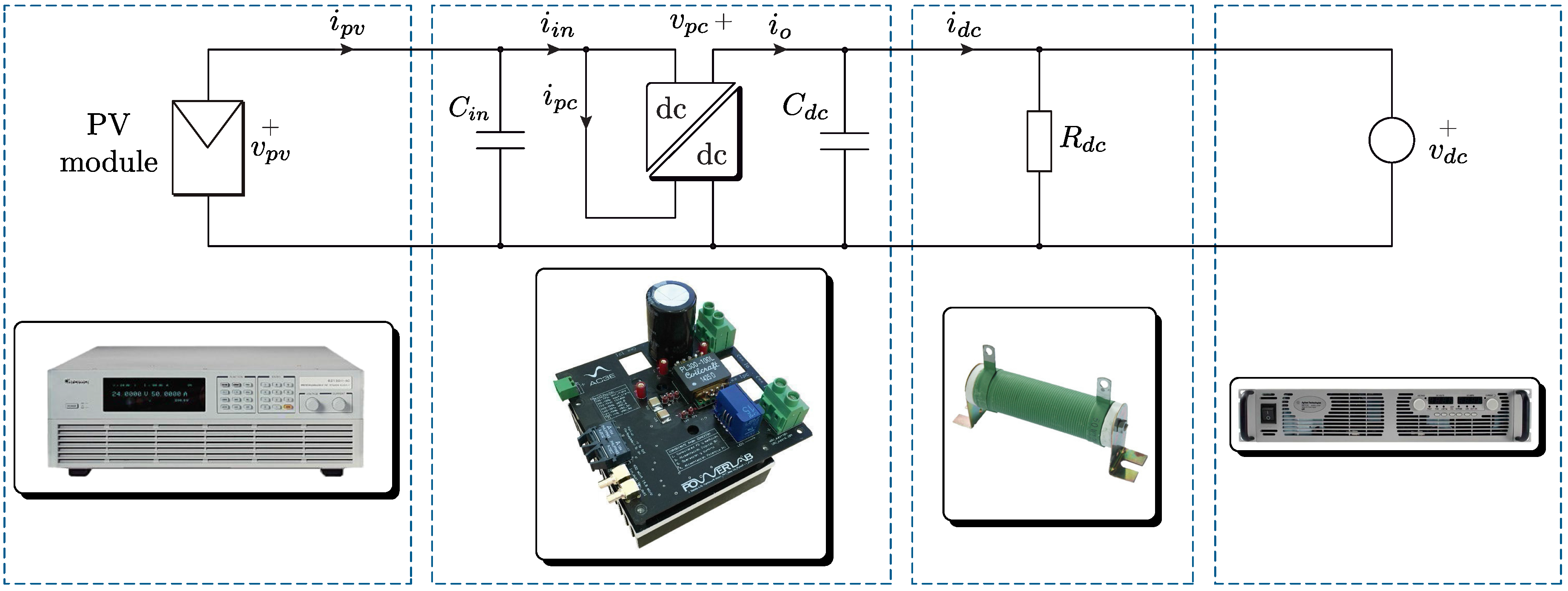
The experimental test bench shown in Figure 4 was built to validate the operation of the proposed topology. The PV system is emulated with the programmable DC-power supply Chroma 62050H-600S, with Solar Array Simulator (600 V/5 kW). The control platform is composed of a dSPACE 1103 controlling the DC-DC converters, a FPGA Spartan-3E generating the high-frequency PWM signals, and an interface board between the dSPACE and the FPGA. The PPC are used to perform the Maximum Power Point Tracking (MPPT) algorithm controlling the input voltage, and the output voltage is fixed by the DC-power supply Agilent N8762A Technologies (600 V/8.5 A) to emulate the grid-tied inverter. The power delivered by the PV system is dissipated in a resistive load.
For the prototype construction, a HF transformer (Coilcraft PL300-100L) is included, which has the transformer turns ratio = 4:4 and it is rated to P = 300 W. The Mosfet (IRFB4019PBF) rated to 17 A@150 V and the Diode (12TQ150(S)) rated to 15A@150 V.
The parameters of the Step-Up Flyback based PPC are: PV voltage = 30 V, input capacitance = 10 μF, clamping capacitance = 5 μF, output capacitance = 1000 μF, transformer turns ratio = 4:4 and switching frequency = 200 kHz.
3.1. Clamping Circuit
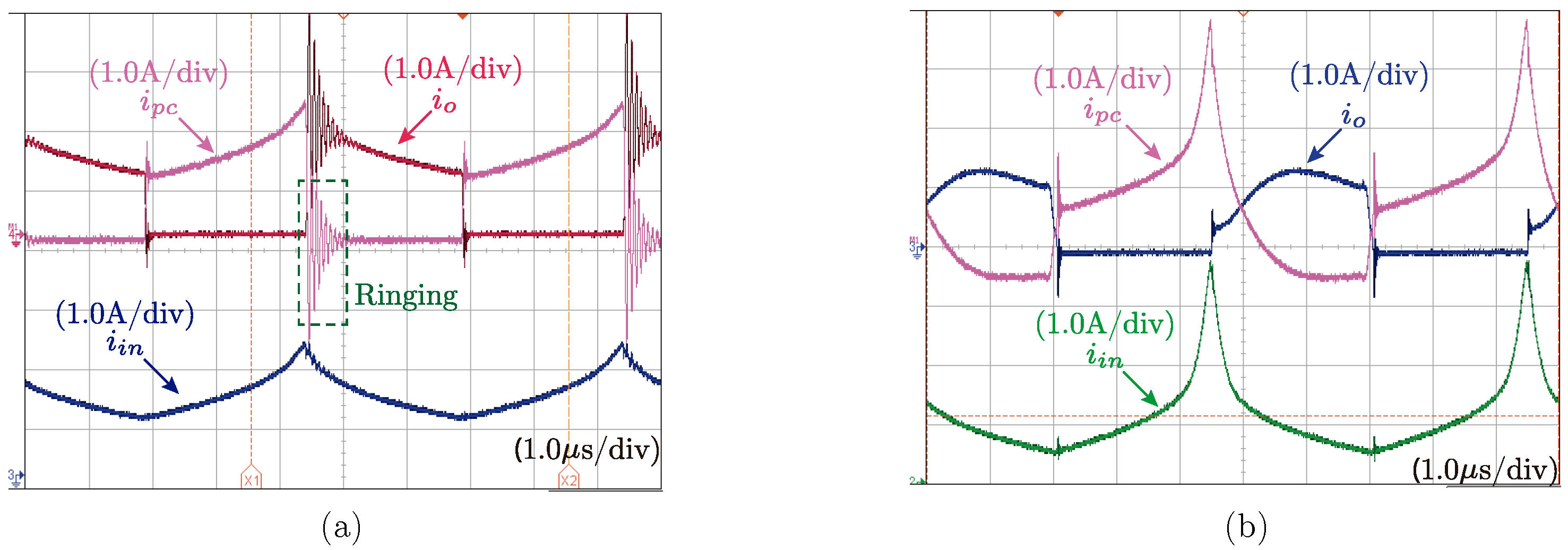
Firstly, the proposed Flyback-based partial power converter was tested without clamping circuit. Measured currents are shown in Figure 5 for the converter working with a duty cycle . In this figure, it can be seen that the resulting input current behave as expected and represented in Figure 2b, being a continuous waveform with reduced ripple around compared with a traditional Flyback converter. In Figure 5a, it can also been observed the presence of an important ringing effect when the main switch turns off. This ringing effect is due to the presence of parasitic elements in the circuit, combined with the fast switching of the devices working at the frequency = 200 kHz. Such phenomenon is not desirable since it implies high stress in the devices resulting in higher losses.
In order to mitigate the ringing effect, a clamping circuit as represented in Figure 2b is used. Measured currents are shown in Figure 5 (b) for the converter working with the same duty cycle , this time using the clamping circuit. As a result of the addition of the clamping circuit, it can be observed that the undesired ringing effect is no more present. The current waveforms are little modified, because of the clamping capacitor included in the auxiliary circuit. However, the main behavior of the converter is similar, in particular regarding the input current being continuous and with reduced ripple around compared with a traditional Flyback converter.
3.2. Converter Operation with
Additional tests have been done to validate the operation of the proposed partial power converter topology under different operating points. First, results are proposed operating the converter with D = 0.63. Figure 6a gives the measured currents. Once again it can be observed that the resulting input current is continuous as observed.
3.3. Converter Operation with
The behavior of the proposed topology has also been verified for duty cycles lower than . Figure 6b gives the currents of the converter operating with . As described in Section 2.2, the proposed topology shows one of its major advantage in contrast to the traditional IPOS configuration while the converter operates with a duty cycle lower than . Indeed, in Figure 6b, it is verified that for a low duty cycle operation, the input current is continuous. On the other hand, in the case of the traditional IPOS configuration made with Flyback converters, the input current as represented in Figure 1 is discontinuous for duty cycle lower than .
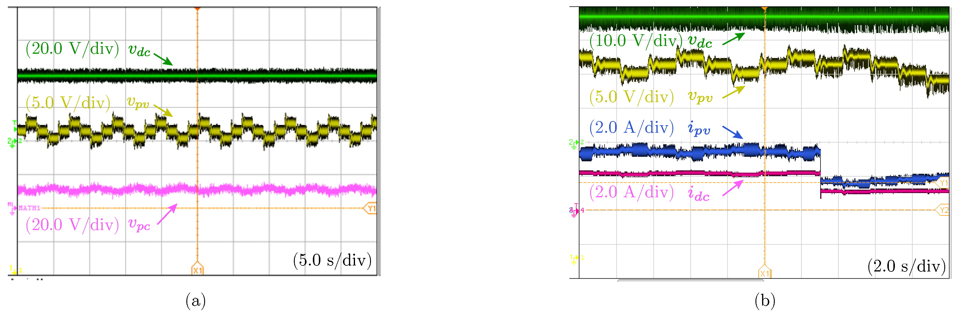
Under constant solar irradiation the parameters evaluated are the voltage and current in the system. The voltages are depicted in Figure 7a, where the P&O MPPT algorithm presents the classical three levels. In traditional PV applications the voltage at the DC-link is fixed by the inverter, then due to the series connection of the PPC, the converter voltage is the difference between and .
The experimental results of the MPPT performance are depicted in Figure 7b, where an irradiation change is made reducing the value around . In this proposed work the Perturb & Observe (P&O) algorithm is implemented due to the simple implementation and effective tracking of the MPP [18]. It is possible to note the constant output voltage , the current reduction at the input and output side of the converter depending on the irradiation change. Moreover, the PV voltage varies until find the maximum power point, where the typical three levels are depicted oscillating around the MPP.
3.4. Converter Efficiency
In order to obtain the experimental efficiency, the power is calculated using the modulated and sampled values of voltage and current. The measurements are taken from the whole power conversion system (PPC configuration), and the isolated DC-DC converter used to make the configuration (Flyback topology).
The DC-stage efficiency , which represents the global conversion efficiency, is calculated based on the measurements at the output side () and the input side ().
On the other hand, the DC-DC efficiency represents the conversion efficiency of the isolated Flyback DC-DC converter used for making the PPC configuration. It is calculated based on the measurements at the output side of the DC-DC Flyback converter () and the input side ().
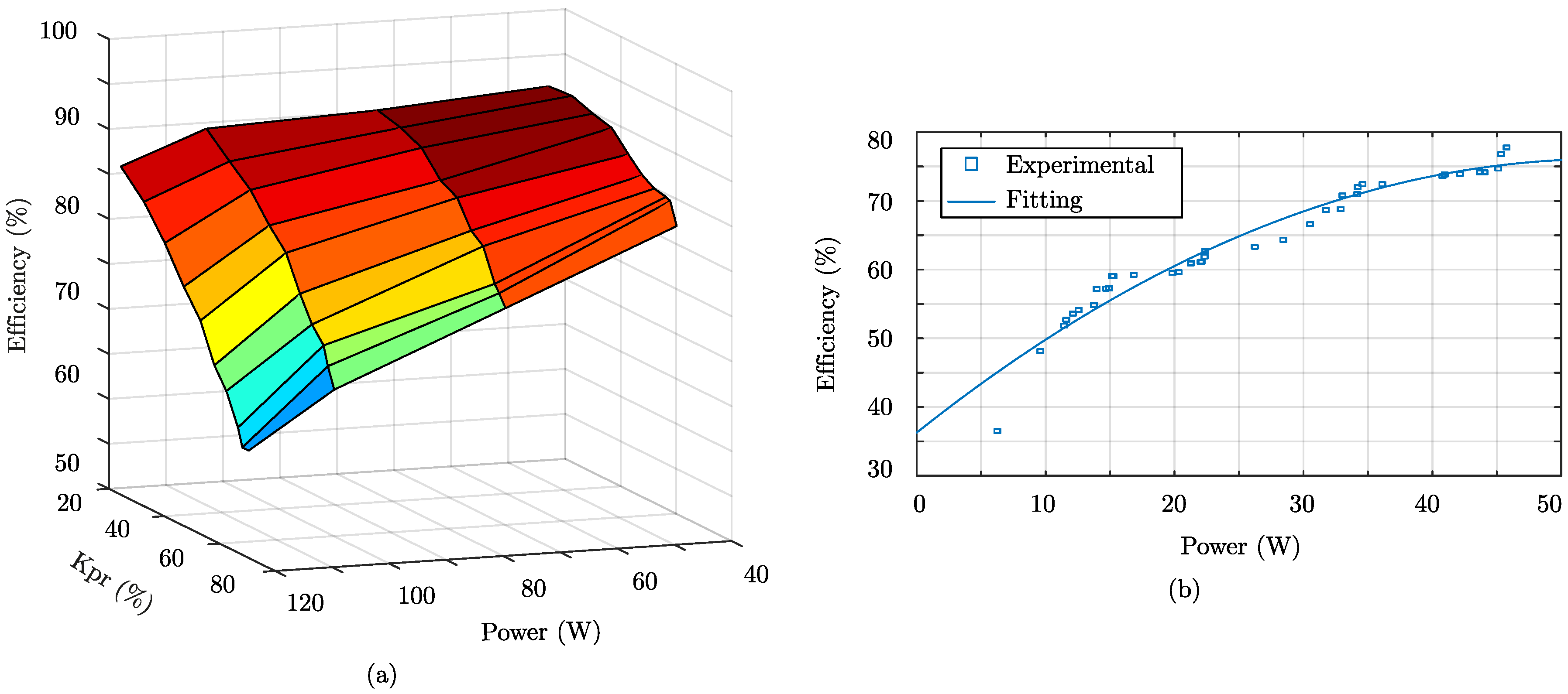
The experimental efficiency waveforms are depicted in Figure 8. The global conversion efficiency of the DC-stage is obtained under different power and partial power ratios . When the converter is operating below of the total power, the global conversion efficiency varies between 70–90%, as depicted in Figure 8a. On the other hand, the conversion efficiency of the DC-DC converter varies between 35–77%, as depicted in Figure 8b, where it is also possible to note the experimental points obtained from measurements and the curve fitting. This can be understood in the sense that the Flyback converter is handling a very low power, in comparison for which it was designed. Moreover, the topology operates with a deep voltage gain as will be explained.
In order to enhance the analysis of efficiency, Table 1 illustrates an experimental operating point for the configuration. As can be seen, the PV system is rated at = 99 W but it is handling a of the total power. The partial power ratio is related to the global voltage gain, which is . However, due to the series connection, the voltage at converter side is very small = 4.8 V, which leads to a deep voltage gain for the isolated Flyback DC-DC converter = 0.15. That is the reason because of the low efficiencies reached with the Flyback converter. However, from the point of view of the whole system it is not a problem when the partial ratio is low, because the DC-DC converter is handling a low power. Therefore, the power loss related to the DC-DC conversion is = 8.12 W, which represents the of the global system losses.
Moreover, as can be realized the DC-DC converter works as buck converter despite of the step-up operation. It means that the topology operation does not define the operation of the PPC configuration. For that reason, for this application it is important to select a topology with a buck-boost operation in order to compensate the required converter voltage . That is also a motivation to use a Flyback instead of other topologies, so that with a turns ratio the voltage gain is not limited because of the inherent buck-boost operation.
Laboratory prototypes are not optimized in their design in terms of efficiency for the power rating in which they operate, particularly due to the fact that semiconductors and modules are designed for full power operation. Consequently, it is expected that for commercial developments, which are optimized in terms of efficiency for a particular power rating, improved efficiencies can be obtained for the DC-DC converter stages, further improving the global system efficiency. In addition, the main point of the contribution is to highlight the increment of the efficiency achieved with the PPC configuration, despite of the lower efficiency of the Flyback DC-DC converter used for the the construction of the PPC.
4. Analysis of the Partial Power Ratio
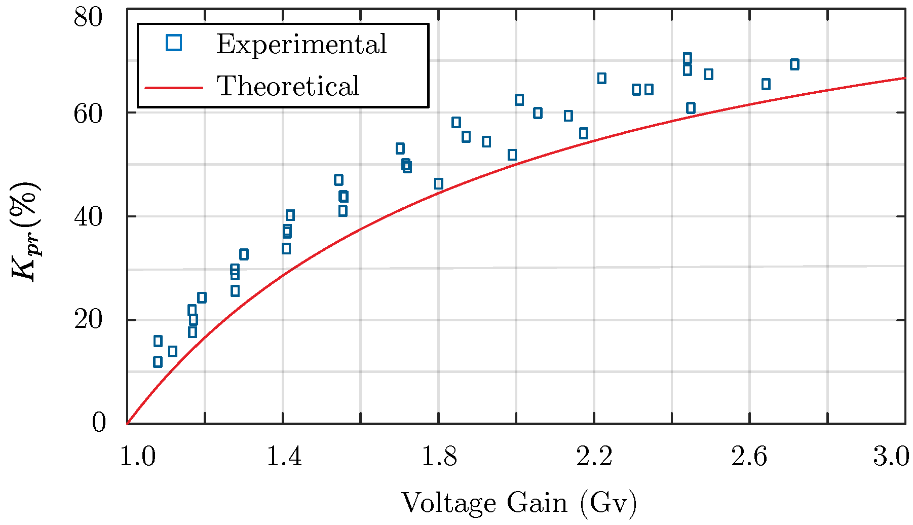
In order to evaluate the ratio of power processed by the converter, the voltage and current are measured at the Mosfet bridge, and the mean value is multiplied in order to obtain the converter power . Then, it is divided by the input power in order to obtain the partial power ratio . The experimental results are shown with points and the theoretical value is shown with a continuous line.
The experimental result for the Step-Up Flyback based PPC is depicted in Figure 9. It is possible to notice the increase of when the voltage gain is also increasing. The behavior fits with the theoretical result in (8). Nevertheless, it presents a small bias but it can be explained in the sense that the theoretical analysis was made considering a global efficiency . Nevertheless, the important fact is the validation of the dependence between the voltage gain and the power processed by the converter.
5. Conclusions
In this work, a partial power converter with interleaved current performance has been proposed. The main feature of the converter consists to obtain, with a single PPC, the current improvement obtained in a classical IPOS configuration of two converters. The proposed topology has been validated in a Flyback-based 100 W laboratory prototype. The experimental results validated the operation depicting a continuous current at the input of the converter, and current ripple reduction around . It is useful in PV applications because it allows a size reduction of the input capacitor filter. In addition, the MPPT performance was also validated under an irradiation change, by using the P&O algorithm. Finally, the tested experimental prototype reaches higher conversion efficiencies compared with the isolated DC-DC converter used to make the PPC configuration.
Future works will related to the evaluation of the IPOS configuration, working with interleaved PPCs. In order to increase the voltage gain, it is necessary to reduce the power processed by the converters even further, and to reduce the input current ripple.
References
Acknowledgments
The authors acknowledge the support provided by CONICYT-PCHA/Doctorado Nacional/ 2016-21160863, by FONDECYT 1171823, AC3E (CONICYT/Basal/FB0008), and SERC Chile (CONICYT/FONDAP/15110019).
Author Contributions
Jaime Wladimir Zapata conceived, designed and performed the experimental evaluations. Gonzalo Carrasco was part of the team to develop the experimental test-bench. Samir Kouro and Hugues Renaudineau were responsible for the guidance and a number of key suggestions.
Conflicts of Interest
The authors declare there is no conflict of interest.
References
- Lian, Y.; Adam, G.; Holliday, D.; Finney, S. Modular input-parallel output-series DC/DC converter control with fault detection and redundancy. IET Gener. Transm. Distrib. 2016, 10, 1361–1369. [Google Scholar] [CrossRef]
- Srighakollapu, N.; Keeramthode, R.; Posa, R. PV Inverter with Input Parallel Output Series Connected Flyback Converters Feeding a Fullbridge Grid Converter. European Patent EP2571154A2, 20 March 2013. [Google Scholar]
- Zapata, J.W.; Kouro, S.; Aguirre, M.; Meynard, T. Model predictive control of interleaved dc-dc stage for photovoltaic microconverters. In Proceedings of the 41st Annual Conference of the IEEE Industrial Electronics Society, IECON 2015, Yokohama, Japan, 9–12 November 2015; pp. 4311–4316. [Google Scholar]
- Muller, S.; Deicke, M.; Doncker, R.W.D. Doubly fed induction generator systems for wind turbines. IEEE Ind. Appl. Mag. 2002, 8, 26–33. [Google Scholar] [CrossRef]
- Kasper, M.; Bortis, D.; Kolar, J.W. Classification and Comparative Evaluation of PV Panel-Integrated DC/DC Converter Concepts. IEEE Trans. Power Electron. 2014, 29, 2511–2526. [Google Scholar] [CrossRef]
- Birchenough, A. A high efficiency DC bus regulator / RPC for spacecraft applications. AIP 2004, 699, 606–613. [Google Scholar]
- Zhou, H.; Zhao, J.; Han, Y. PV Balancers: Concept, Architectures, and Realization. IEEE Trans. Power Electron. 2015, 30, 3479–3487. [Google Scholar] [CrossRef]
- Marzouk, A.; Fournier-Bidoz, S.; Yablecki, J.; McLean, K.; Trescases, O. Analysis of partial power processing distributed MPPT for a PV powered electric aircraft. In Proceedings of the 2014 International Power Electronics Conference (IPEC-Hiroshima 2014—ECCE-ASIA), Hiroshima, Japan, 18–21 May 2014; pp. 3496–3502. [Google Scholar]
- Lee, J.P.; Min, B.D.; Kim, T.J.; Yoo, D.W.; Yoo, J.Y. A Novel Topology for Photovoltaic DC/DC Full-Bridge Converter With Flat Efficiency Under Wide PV Module Voltage and Load Range. IEEE Trans. Ind. Electron. 2008, 55, 2655–2663. [Google Scholar] [CrossRef]
- Min, B.D.; Lee, J.P.; Kim, J.H.; Kim, T.J.; Yoo, D.W.; Song, E.H. A New Topology With High Efficiency Throughout All Load Range for Photovoltaic PCS. IEEE Trans. Ind. Electron. 2009, 56, 4427–4435. [Google Scholar]
- Kim, H.; Kim, J.; Kim, H.; Lee, K.; Kim, J.; Yoo, D.; Shin, D. A high efficiency photovoltaic module integrated converter with the asymmetrical half-bridge flyback converter. Sol. Energy 2010, 84, 1376–1381. [Google Scholar] [CrossRef]
- Zhao, J.; Yeates, K.; Han, Y. Analysis of high efficiency DC/DC converter processing partial input/output power. In Proceedings of the 2013 IEEE 14th Workshop on Control and Modeling for Power Electronics (COMPEL), Salt Lake City, UT, USA, 23–26 June 2013; pp. 1–8. [Google Scholar]
- Harfman-Todorovic, M.; Tao, F.; Agamy, M.; Dong, D.; Liu, X.; Garces, L.; Zhou, R.; Delgado, E.; Marabell, D.; Stephens, C.; et al. A high efficiency PV micro-inverter with grid support functions. In Proceedings of the 2014 IEEE Energy Conversion Congress and Exposition (ECCE), Pittsburgh, PA, USA, 14–18 September 2014; pp. 4244–4250. [Google Scholar]
- Zapata, J.W.; Renaudineau, H.; Kouro, S.; Perez, M.A.; Meynard, T.A. Partial power DC-DC converter for photovoltaic microinverters. In Proceedings of the 42nd Annual Conference of the IEEE Industrial Electronics Society, IECON 2016, Florence, Italy, 23–26 October 2016; pp. 6740–6745. [Google Scholar]
- Kouro, S.; Leon, J.; Vinnikov, D.; Franquelo, L. Grid-Connected Photovoltaic Systems: An Overview of Recent Research and Emerging PV Converter Technology. IEEE Ind. Electron. Mag. 2015, 9, 47–61. [Google Scholar] [CrossRef]
- Fornage, M. Method and Apparatus for Converting Direct Current To Alternating Current. U.S. Patent 0221267A1, 27 September 2007. [Google Scholar]
- Kouro, S.; Wu, B.; Abu-Rub, H.; Blaabjerg, F. Chapter 7: Photovoltaic energy conversion systems. In Power Electronics for Renewable Energy Systems, Transportation and Industrial Applications; Wiley: Hoboken, NJ, USA, 2014. [Google Scholar]
- Femia, N.; Petrone, G.; Spagnuolo, G.; Vitelli, M. Optimization of perturb and observe maximum power point tracking method. IEEE Trans. Power Electron. 2005, 20, 963–973. [Google Scholar] [CrossRef]
Figure 1.
Traditional interleaved configuration using a Flyback topology.

Figure 2.
(a) Configuration of the partial power converter. (b) Proposed topology using a Flyback converter.
Figure 2.
(a) Configuration of the partial power converter. (b) Proposed topology using a Flyback converter.

Figure 3.
(a) Partial power operation range of the Step-Up Partial Power Converter (PPC). (b) Operation range of the Step-Up Flyback based PPC for different transformer turns ratio .
Figure 3.
(a) Partial power operation range of the Step-Up Partial Power Converter (PPC). (b) Operation range of the Step-Up Flyback based PPC for different transformer turns ratio .

Figure 4.
Experimental test bench for the evaluation of the proposed converter.

Figure 5.
Current measurements in the proposed converter. (a) Without the clamping circuit and . (b) With the clamping circuit and .
Figure 5.
Current measurements in the proposed converter. (a) Without the clamping circuit and . (b) With the clamping circuit and .

Figure 6.
Current measurements. (a) With the clamping circuit and . (b) With the clamping circuit and .
Figure 6.
Current measurements. (a) With the clamping circuit and . (b) With the clamping circuit and .

Figure 7.
Maximum Power Point Tracking (MPPT) performance in the Step-Up based PPC: (a) under constant solar irradiation; (b) under a solar irradiation change.
Figure 7.
Maximum Power Point Tracking (MPPT) performance in the Step-Up based PPC: (a) under constant solar irradiation; (b) under a solar irradiation change.

Figure 8.
Curve of experimental efficiency: (a) Total power conversion system. (b) Isolated DC-DC converter in the Step-Up Flyback based PPC.
Figure 8.
Curve of experimental efficiency: (a) Total power conversion system. (b) Isolated DC-DC converter in the Step-Up Flyback based PPC.

Figure 9.
Experimental partial power ratio for the Step-Up Flyback based PPC.


Table 1.
Experimental evaluation points.
| Parameters | Value | Parameters | Value |
|---|---|---|---|
| System Power (W) | 99 | Converter voltage (V) | 4.8 |
| DC-DC Power (W) | 19.8 | Global Voltage gain | 1.17 |
| 20 | DC-DC Voltage gain | 0.15 | |
| Input voltage (V) | 27.9 | DC-stage efficiency (%) | 90 |
| Output voltage (V) | 32.7 | DC-DC efficiency | 59 |
© 2018 by the authors. Licensee MDPI, Basel, Switzerland. This article is an open access article distributed under the terms and conditions of the Creative Commons Attribution (CC BY) license (http://creativecommons.org/licenses/by/4.0/).
Share and Cite
MDPI and ACS Style
Zapata, J.W.; Kouro, S.; Carrasco, G.; Renaudineau, H. Step-Up Partial Power DC-DC Converters for Two-Stage PV Systems with Interleaved Current Performance. Energies 2018, 11, 357. https://0-doi-org.brum.beds.ac.uk/10.3390/en11020357
AMA Style
Zapata JW, Kouro S, Carrasco G, Renaudineau H. Step-Up Partial Power DC-DC Converters for Two-Stage PV Systems with Interleaved Current Performance. Energies. 2018; 11(2):357. https://0-doi-org.brum.beds.ac.uk/10.3390/en11020357
Chicago/Turabian StyleZapata, Jaime Wladimir, Samir Kouro, Gonzalo Carrasco, and Hugues Renaudineau. 2018. "Step-Up Partial Power DC-DC Converters for Two-Stage PV Systems with Interleaved Current Performance" Energies 11, no. 2: 357. https://0-doi-org.brum.beds.ac.uk/10.3390/en11020357
Note that from the first issue of 2016, this journal uses article numbers instead of page numbers. See further details here.