A Hybrid Filtering Technique-Based PLL Targeting Fast and Robust Tracking Performance under Distorted Grid Conditions


1
School of Electrical Engineering, Shenyang University of Technology, Shenyang 110870, China
2
Liaoning Province Electric Power Company, Shenyang 110006, China
*
Author to whom correspondence should be addressed.
Energies 2018, 11(4), 973; https://0-doi-org.brum.beds.ac.uk/10.3390/en11040973
Submission received: 28 March 2018
/
Revised: 11 April 2018
/
Accepted: 12 April 2018
/
Published: 18 April 2018
(This article belongs to the Special Issue Emerging Power Electronics Technologies for Power Systems and Machine Drives)
Abstract
:In most grid-connected power converter applications, the phase-locked loop (PLL) is probably the most widespread grid synchronization technique, owing to its simple implementation. However, its phase-tracking performance tends to worsen when the grid voltage is under unbalanced and distorted conditions. Many filtering techniques are utilized to solve this problem, however, at the cost of slowing down the transient response. It is a major challenge for PLL to achieve a satisfactory dynamic performance without degrading its filtering capability. To tackle this challenge, a hybrid filtering technique is proposed in this paper. Our idea is to eliminate the fundamental frequency negative sequence (FFNS) and other harmonic sequences at the prefiltering stage and inner loop of PLL, respectively. Second-order generalized integrators (SOGIs) are used to remove FFNS before the Park transformation. This makes moving average filters (MAFs) eliminate other harmonics with a narrowed window length, which means the time delay that is caused by MAFs is reduced. The entire hybrid filtering technique is included in a quasi-type-1 PLL structure (QT1-PLL), which can provide a rapid dynamic behavior. The small-signal model of the proposed PLL is established. Based on this model, the parameter design guidelines targeting the fast transient response are given. Comprehensive experiments are carried out to confirm the effectiveness of our method. The results show that the settling time of the proposed PLL is less than one grid cycle, which is shorter than most of the widespread PLLs. The harmonic rejection capability is also better than other methods, under both nominal and adverse grid conditions.
1. Introduction
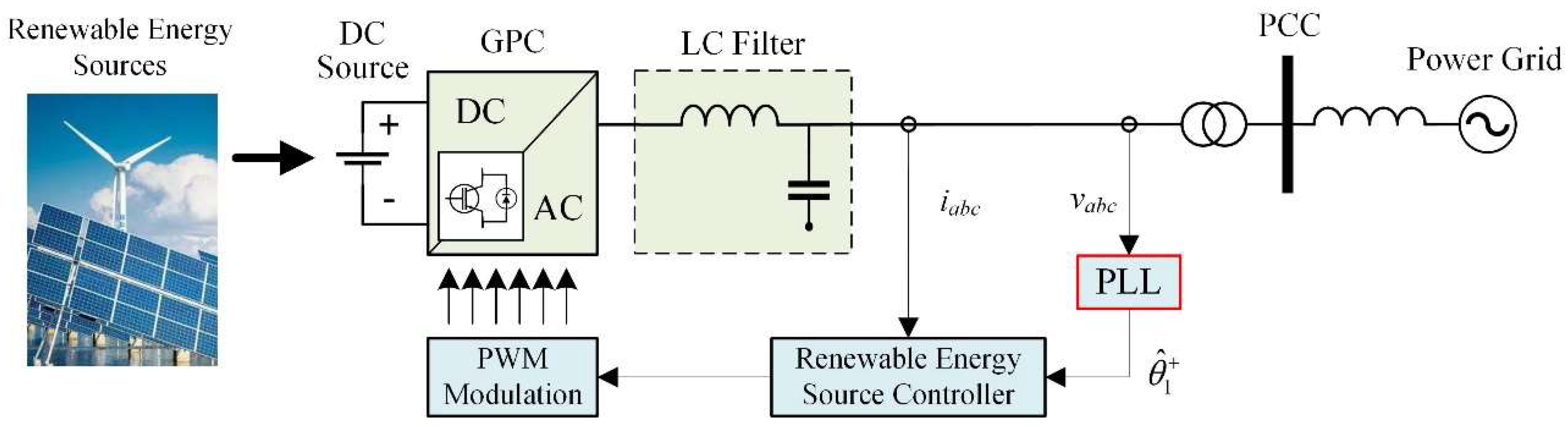
Grid synchronization is an important control aspect in grid-connected power converter (GPC) applications. Among various synchronization techniques, synchronous-reference frame phase-locked loop (SRF-PLL) is probably the most widely used method, owing to its simple implementation and fast dynamic response [1,2]. The control of GPC is based on the estimated phase angle of grid voltage at the point of common coupling (PCC) through PLL, as shown in Figure 1. However, with the increasing penetration of the distributed generation system and renewable energy sources, power quality issues have been introduced, which may cause grid voltages to be polluted [3,4]. Under such unbalanced and distorted grid voltage conditions, the phase-tracking performance of SRF-PLL deteriorates dramatically [5,6]. To solve this problem, many filtering techniques, such as the low-pass filter (LPF) and moving average filter (MAF), are used to attenuate harmonic voltage components at the cost of slowing down transient response [7]. To achieve a satisfactory filtering capability without degrading the dynamic performance is a major challenge of PLL under distorted grid conditions [8]. It is also a focus issue of renewable energy systems [9,10,11].
To achieve a better dynamic performance, many advanced PLLs have been developed using hybrid filtering techniques. These hybrid filtering techniques can be divided into two categories: LPF-based hybrid filters and MAF-based hybrid filters. LPF-based hybrid filters, acting as a prefiltering stage, are commonly arranged at the outer loop of many advanced PLLs, such as the dual second-order generalized integrator-based PLL (DSOGI-PLL) [12], multiple complex-coefficient filter-based PLL (MCCF-PLL) [13], multiple reference frame-based PLL (MRF-PLL) [14], and decoupled double synchronous-reference frame PLL (DDSRF-PLL) [15]. These kinds of hybrid filters can be considered as two parts that are cascade-connected. One part is responsible for eliminating the fundamental frequency negative sequence (FFNS) component, which acts as a notch filter. Another part, which acts as a LPF, is employed to attenuate other disturbances. Since the FFNS component is totally rejected, the bandwidth of the open-loop transfer function can be increased without considering the influence of FFNS. However, the LPF-based hybrid filter can only attenuate, but not eliminate, high order harmonics [16]. The harmonic rejection capability is not satisfactory under the highly distorted grid conditions.
Compared with the LPF-based hybrid filter, the MAF-based hybrid filter can offer improved disturbances rejection, since the MAF can completely block an infinite set of harmonics. This is a positive property, which enables the MAF to act as an ideal LPF under certain conditions [17]. With this interesting feature, many MAF-based hybrid filters have recently been proposed. In Reference [18], a hybrid filtering stage consists of a special proportional component and MAFs with a narrowed window length (Tω) are incorporated into the inner loop of the SRF-PLL. Although the settling time and harmonic rejection performance of the so-called differential-MAF PLL (DMAF-PLL) is satisfactory, the overshoot of the estimated frequency under the phase jump condition is too large. This undesired transient behavior may violate many grid codes [19,20] and cause mistaken tripping operation. In Reference [21], a synchronous/stationary reference-frame filtering-based hybrid PLL (HPLL) is proposed with a rapid transient response. Delayed signal cancellation (DSC) operators and MAFs are arranged at the outer loop and inner loop, respectively. However, the phase-tracking performance deteriorates when the grid frequency is off-nominal. In Reference [22], a complex notch filter (CNF) is employed in the filtering stage of the proposed complex notch filter-based quasi-type-1 PLL (CNF-QT1-PLL) to eliminate the FFNS component. Similar to DMAF-PLL, the Tω of MAFs in CNF-QT1-PLL are also reduced. The settling time of CNF-QT1-PLL is less than one grid cycle, which is smaller than most of the existing PLLs. However, the complex notch filter arranged at the inner loop is complicated by a large computational burden. As with many other MAF-based PLLs, the filtering capability degrades when the grid frequency is under an off-nominal value.
Another effective way to improve the dynamic performance is to use a modified PLL structure. Some PLLs with a secondary control path have been proposed in the literature [23,24]. The secondary control path can increase the bandwidth of PLL and accelerate the transient response. However, according to the analysis in Reference [25], the utilization of a secondary control path can increase the type of open loop transfer function, which may aggravate the stability problem and increase the implementation complexity. Recently, a modified PLL structure, named quasi-type-1 PLL (QT1-PLL), was proposed in Reference [26]. Different from the conventional type-2 SRF-PLL, QT1-PLL removes the integral operation in the proportional-integral (PI) controller and offers a feed-forward control path to the output. This change provides an additional open-loop pole at the origin, which enables QT1-PLL to provide a rapid dynamic behavior and a zero average phase error under the frequency drift. Moreover, the filtering stage of QT1-PLL is based on MAFs, which can completely eliminate disturbances. The aforementioned HPLL and CNF-QT1-PLL also inherit the advantages of QT1-PLL. These QT1 structure-based PLLs have an excellent disturbance rejection when the grid frequency is at nominal value. However, the filtering capability decreases when increasing the frequency deviation from its nominal value. Although this problem can be solved by using a frequency-adaptive MAF, this solution will increase the implementation complexity dramatically.
To tackle this challenge mentioned above, a hybrid filtering technique-based PLL is proposed in this paper, aiming at fast and robust phase-tracking performance. By using a DSOGI-based prefiltering stage and MAFs with a narrowed Tω, FFNS and other harmonic disturbances are totally removed in the stationary reference frame and synchronous reference frame, respectively. In addition, the dynamic performance is directly considered in our design procedure. Thanks to our technique, the convergence time of the transient behavior is reduced to less than one grid cycle. The proposed PLL also provides a desired filtering capability under both nominal and off-nominal grid frequency conditions. Moreover, the digital implementation is not complex. To evaluate the performance, a comprehensive experimental study is carried out under phase jump, frequency step change, frequency ramp change, voltage sag, and distorted grid voltages. The results confirm the effectiveness of the proposed PLL.
This paper is organized as follows. A brief overview of QT1-PLL is provided in Section 2. The proposed PLL is described in detail in Section 3. The small-signal model and parameter design guidelines are given in Section 4. In Section 5, experimental results are provided to make a comprehensive comparison. Finally, Section 6 concludes this paper.
2. Brief Overview of QT1-PLL
Since the proposed method was implemented in a QT1-PLL structure, this section provides a brief overview and analysis of QT1-PLL.
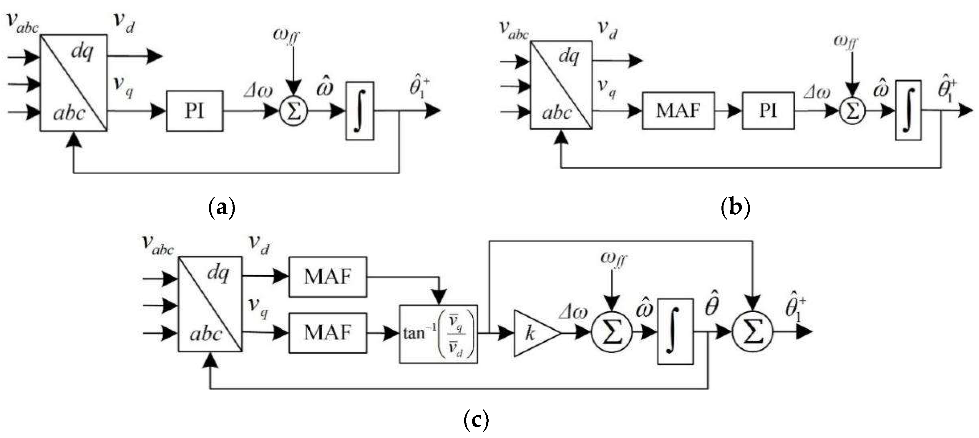
QT1-PLL was derived from SRF-PLL and MAF-PLL. Figure 2 shows the block diagrams of these three PLLs. vabc represents the three-phase voltage, vd and vq are d-axis and q-axis components of vabc, and ωff is the nominal grid frequency. ∆ω represents the deviation of input frequency. and are the estimation of grid frequency and phase, respectively. According to the previous study on small-signal models in References [26], the open-loop transfer functions are as follows.
where
and kp and ki are the proportional factor and integral factor, respectively, in the PI controller. Substituting Equation (4) into Equations (2) and (3) yields the equations as follows:
Compared with SRF-PLL and QT1-PLL, GolMAF(s) had one more pole. With only two poles at the origin, QT1-PLL had a bigger bandwidth than MAF-PLL, which was similar to SRF-PLL.
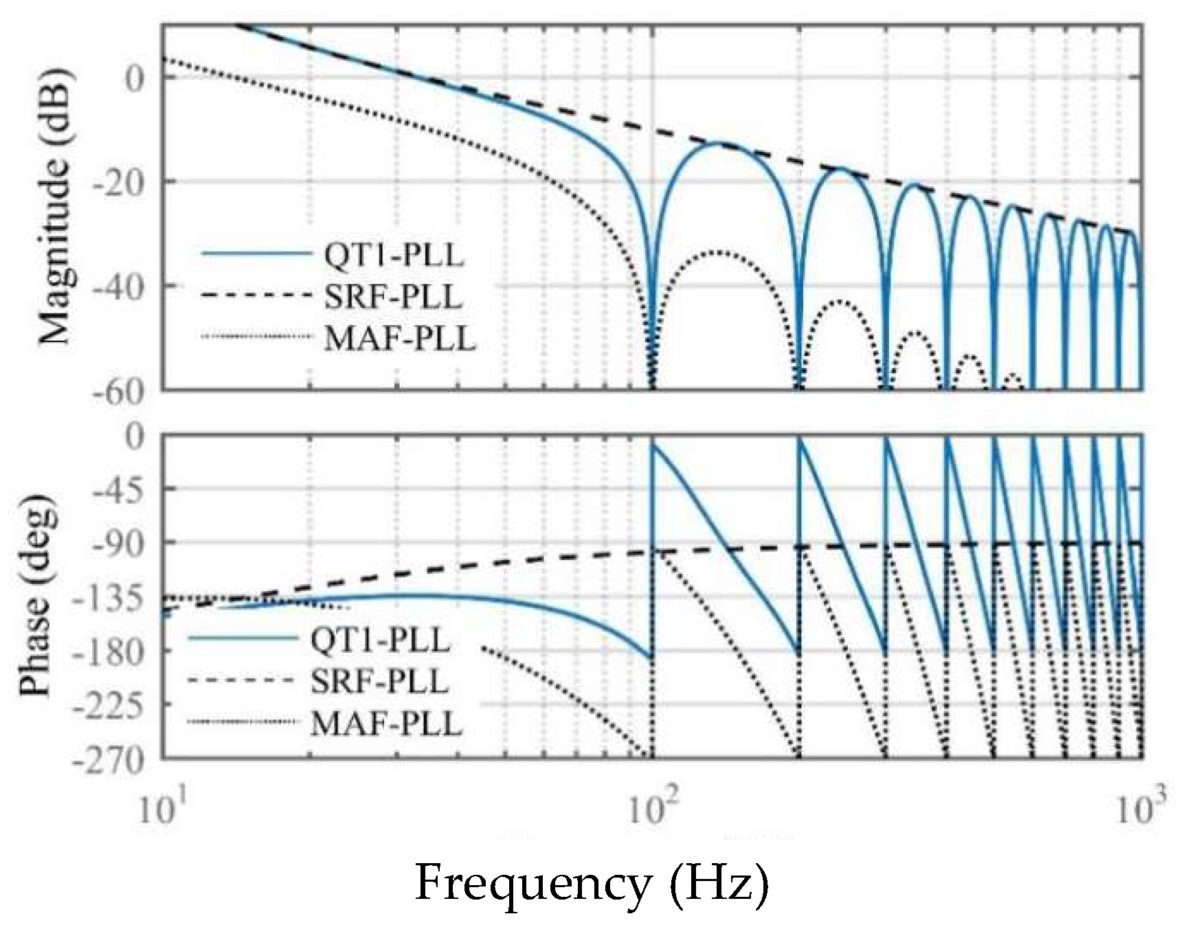
The open-loop bode diagrams of these PLLs are depicted in Figure 3. It was observed that both QT1-PLL and MAF-PLL could eliminate dominant harmonic components (e.g., −1st, −5th, +7th, −11th, +13th, etc.) [16]. QT1-PLL could achieve an ideal filtering capability and rapid transient response at the same time. However, when the grid frequency drifted from its nominal value, the disturbances rejection capability of the frequency-fixed MAF decreased. Observing the bode diagram, the amplitude of QT1-PLL at a nearby harmonic frequency was larger than that in MAF-PLL, which meant that QT1-PLL’s phase tracking error was larger than that in MAF-PLL, under such conditions. This defect also existed in CNF-QT1-PLL. Although the drawback could be solved by making the MAF frequency-adaptive, the digital implementation of a frequency-adaptive MAF was complicated. The detailed realization methods can be found in Reference [17].
3. The Description of the Proposed PLL
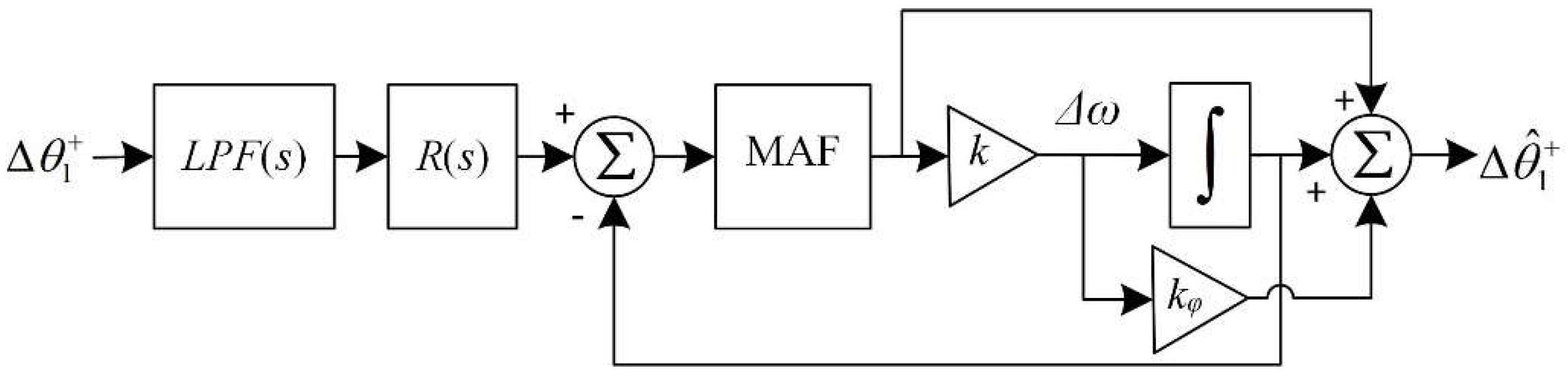
To overcome the drawbacks of QT1-PLL and achieve a fast and robust phase-tracking performance, a hybrid filtering technique-based PLL was proposed in this section. Figure 4 illustrates the block diagram of the proposed PLL.
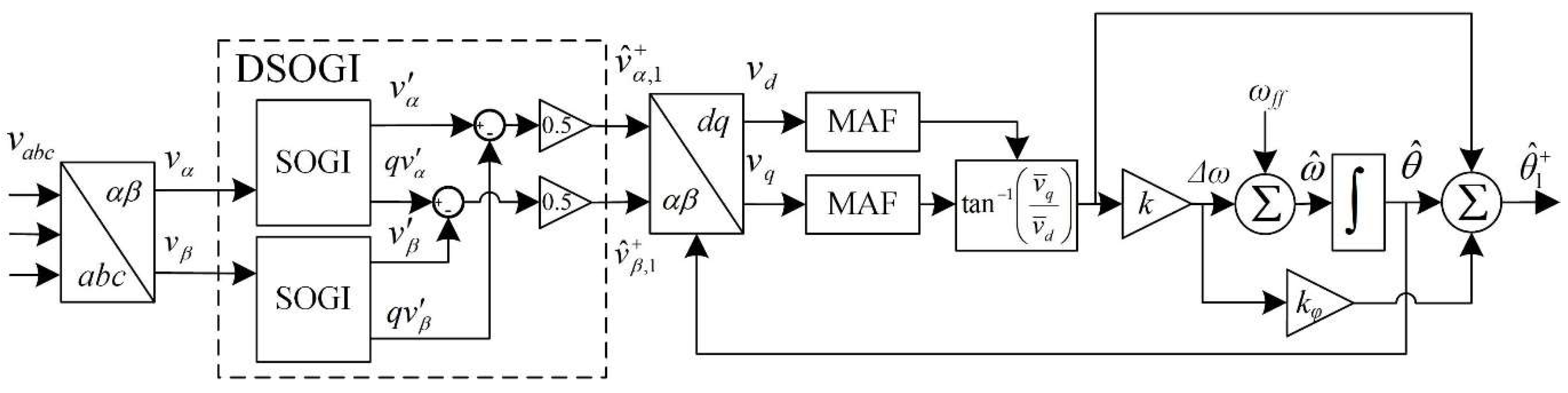
As shown in Figure 4, the filtering stage in the proposed PLL consisted of two parts. The prefiltering stage—DSOGI(as shown in Figure 5)—was arranged at the outer loop, which was responsible for eliminating FFNS and cutting down on other harmonics. MAFs were incorporated into the inner loop to eliminate other harmonics in the dq-frame. Since the dominant harmonic components in the dq-frame were −100 Hz, ±300 Hz, ±600 Hz, etc., listed in Reference [22], and FFNS was already removed by the prefiltering stage, the Tω of MAFs was reduced to 1/300 s. kφ was the phase-compensation factor, which is discussed below.
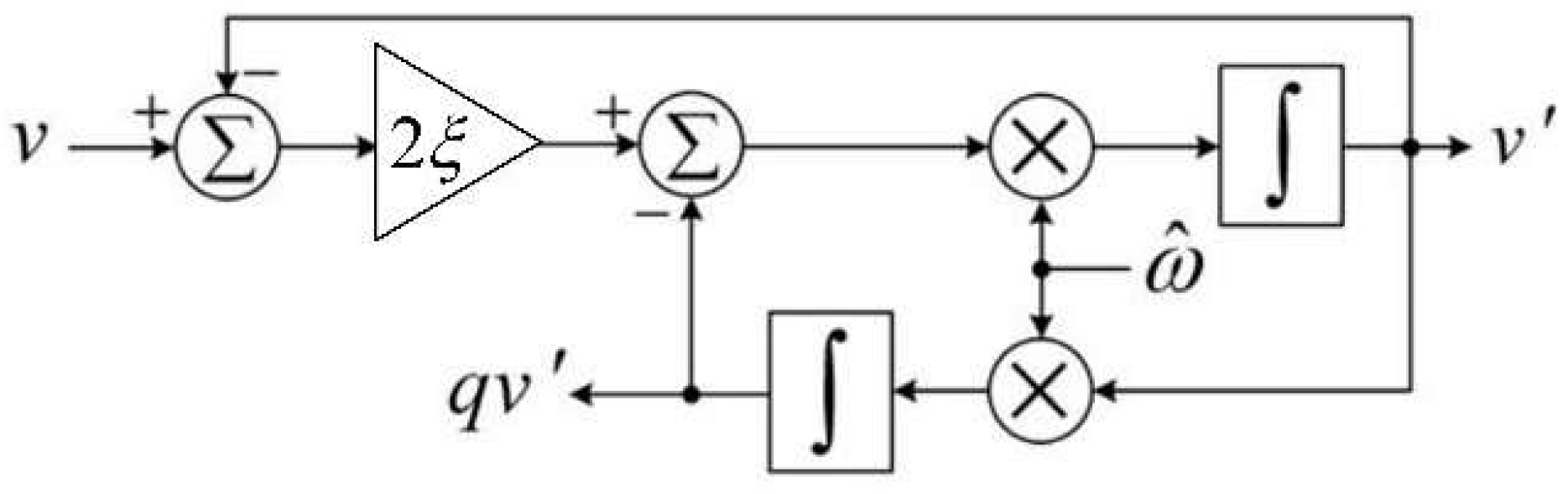
As stated in Reference [27], the damping factor ξ in SOGI was chosen to be 0.7. The complex transfer function of DSOGI can be expressed as follows.
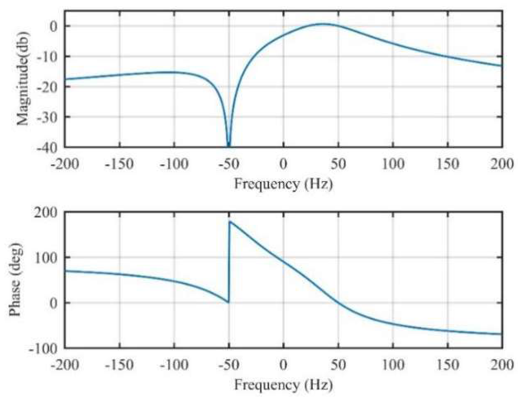
According to Equation (7), the bode plot of DSOGI is depicted in Figure 6. DSOGI provided a unity amplitude and a zero phase degree at 50 Hz. The FFNS component (−50 Hz) was also filtered out. This frequency characteristic could fulfill the disturbance rejection task of DSOGI in the αβ-frame, mentioned above.
It should be noted that a phase shift occurred when the grid frequency drifted from its nominal value. This resulted in a phase-tracking error. To compensate for this error, frequency deviation ∆ω could be feedforwarded at the output of the PLL. Observing Figure 6, the phase shift caused by DSOGI could be approximated by the slope rate of the phase-frequency characteristic, around 50 Hz, as follows:
Since the output of gain k is ∆ω, the phase error can be easily compensated for by choosing kφ to be 0.004333.
To evaluate the filtering performance of the entire hybrid filtering technique, DSOGI(s) could be transformed to the synchronous reference frame as follows:
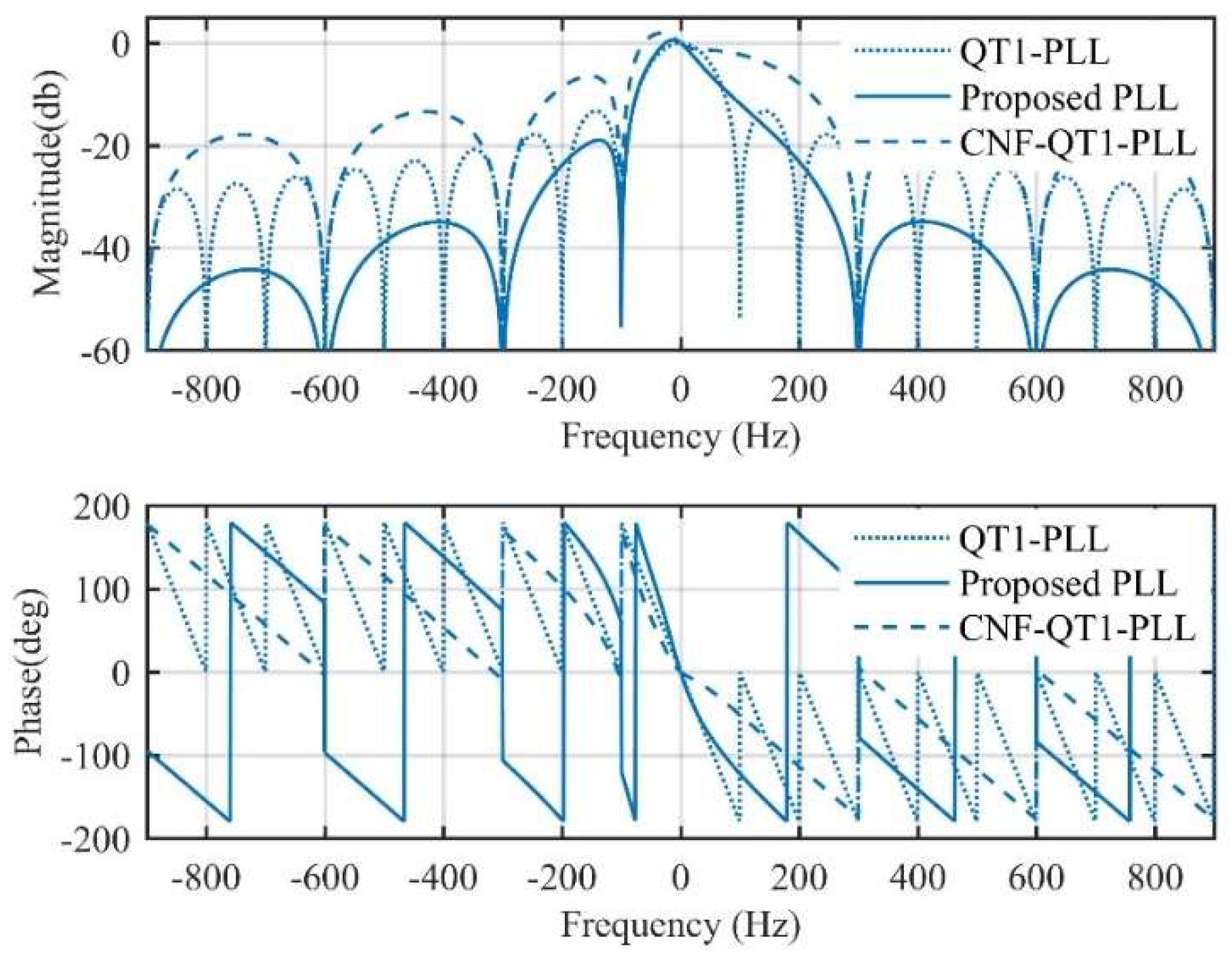
Combined with MAF at the inner loop, the hybrid filter can be expressed as follows:
where Tω is 1/300. The bode plot of H(s) is depicted in Figure 7. The filtering stages of CNF-QT1-PLL and QT1-PLL are also examined in Figure 7. Since the filtering stage was examined in the dq-frame, the dominant disturbances turned out to be −100 Hz, ±300 Hz, ±600 Hz, etc. [22]. All three hybrid filtering techniques could reject harmonics completely. In addition, the proposed PLL could mitigate more disturbance components nearby the dominant harmonic frequencies. The magnitude-frequency characteristic of the proposed PLL around −100 Hz, ±300 Hz, and ±600 Hz was lower than the other two methods. It was useful when the grid frequency was off-nominal, since the non-adaptive MAF could also offer a satisfactory filtering capability under such conditions. This advantage was evaluated by comparative experiments in Section 5.
4. Modeling and Parameters Design Procedure
In this section, according to the structure shown in Figure 3, a small-signal model of the proposed PLL is presented at first. Then, aiming at a rapid transient response, the parameter design guidelines are given. The stability of the system is also discussed.
4.1. Small-Signal Model
Since the small-signal model presented in this section was established in the dq-frame, DSOGI(s) was transformed into the dq-frame at first, using Equation (9). By performing some formula derivation, Equation (9) is written as follows:
where
R(s) and Q(s) are the real part and imaginary part of CNF(s), as follows:
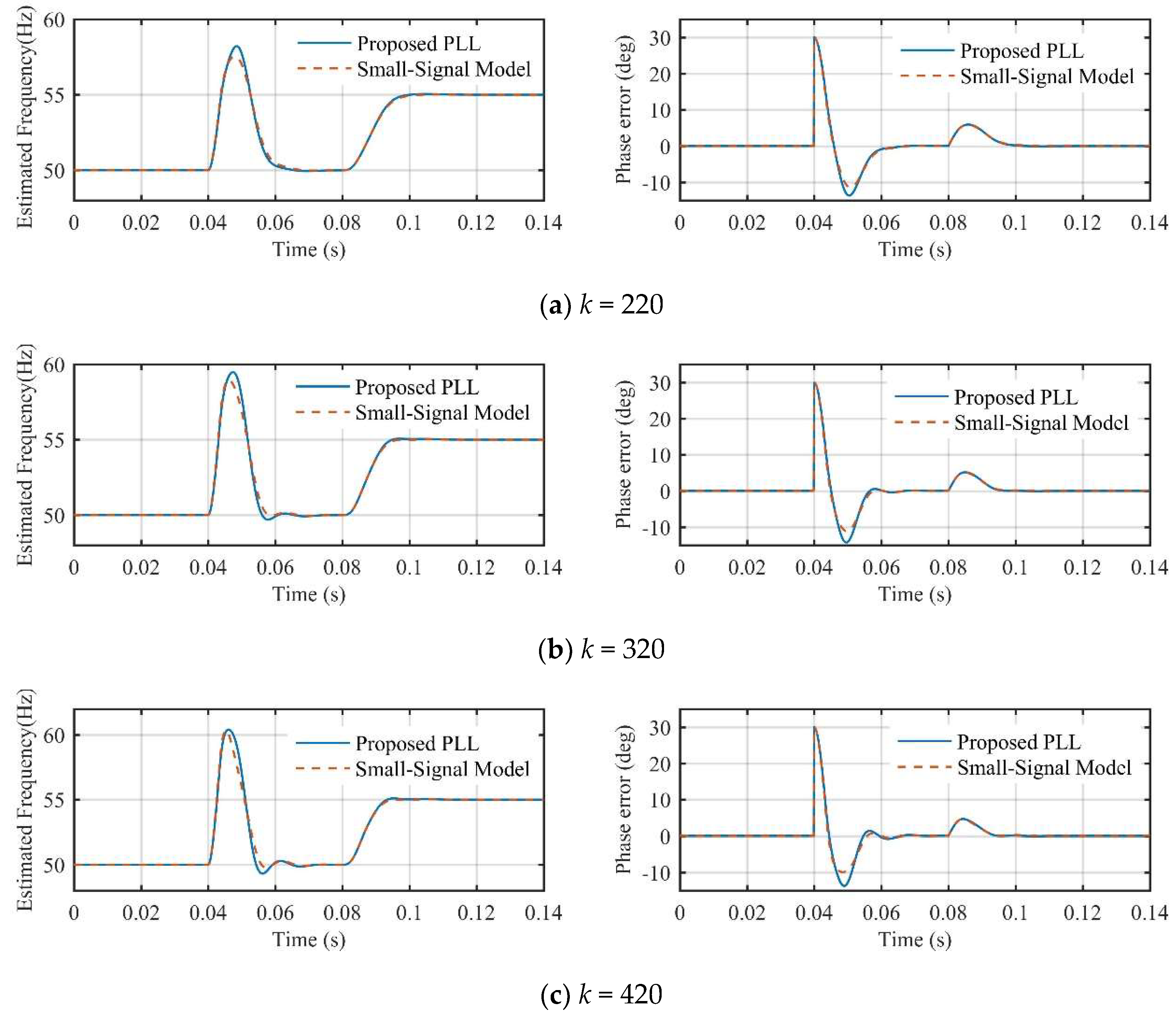
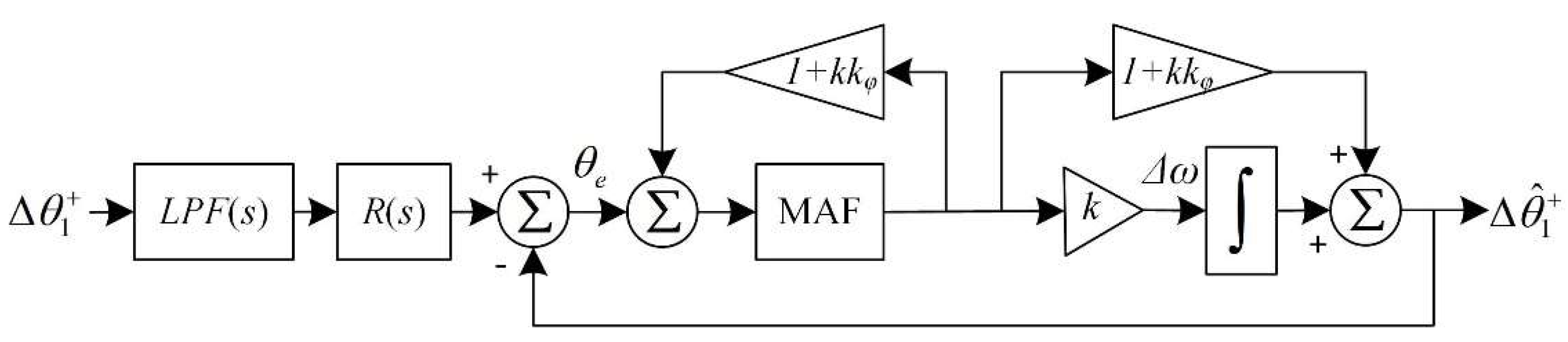
Then, the small-signal model of the proposed PLL is obtained in Figure 8. CNF(s) was simplified by R(s). The accuracy of this model is examined in Figure 9.
The model accuracy was evaluated under a +30° phase jump at 0.04 s and a +5 Hz frequency step change at 0.08 s. Observing Figure 8, it was seen that the model could predict the dynamic behavior of the proposed PLL with sufficient accuracy when the control parameter (k) was selected with a different value. The negligible modeling error was mainly caused by neglecting the Q(s) of CNF(s) in the modeling procedure.
4.2. Parameter Design Procedure
As discussed in Section 3, Tω, ξ, and kφ were chosen to be 1/300, 0.7, and 0.004333, respectively. k was the only parameter to be designed.
To make the design procedure more convenient, some block diagram algebra was applied to Figure 8. An equivalent small-signal model was obtained, as shown in Figure 10. Hence, the phase-tracking error transfer function is as follows:
where θe represents the phase error. Gol(s) is the open loop transfer function of the inner loop of the proposed PLL, as follows:
Based on Ge(s), the phase error under a ∆θ phase jump condition can be written as follows:
In response to a ∆ω frequency step change, the phase error is as follows:
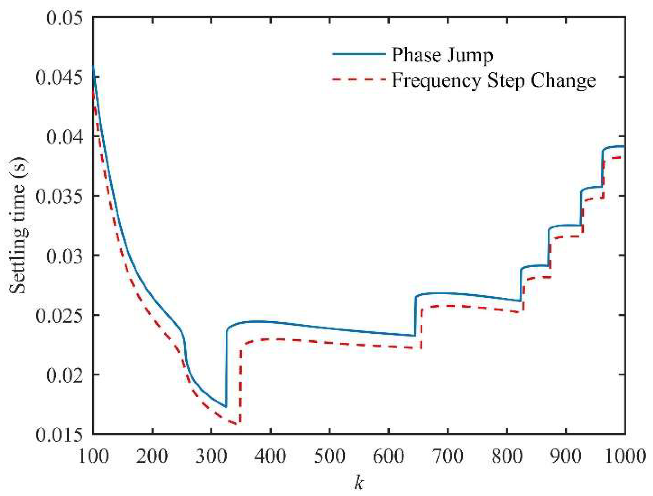
By using the inverse Laplace transform on Equations (18) and (19), the variations of the 2% settling time under the phase jump and frequency step change as a function of k are depicted in Figure 11. To achieve a rapid dynamic response under both of the conditions, k was chosen to be 320.
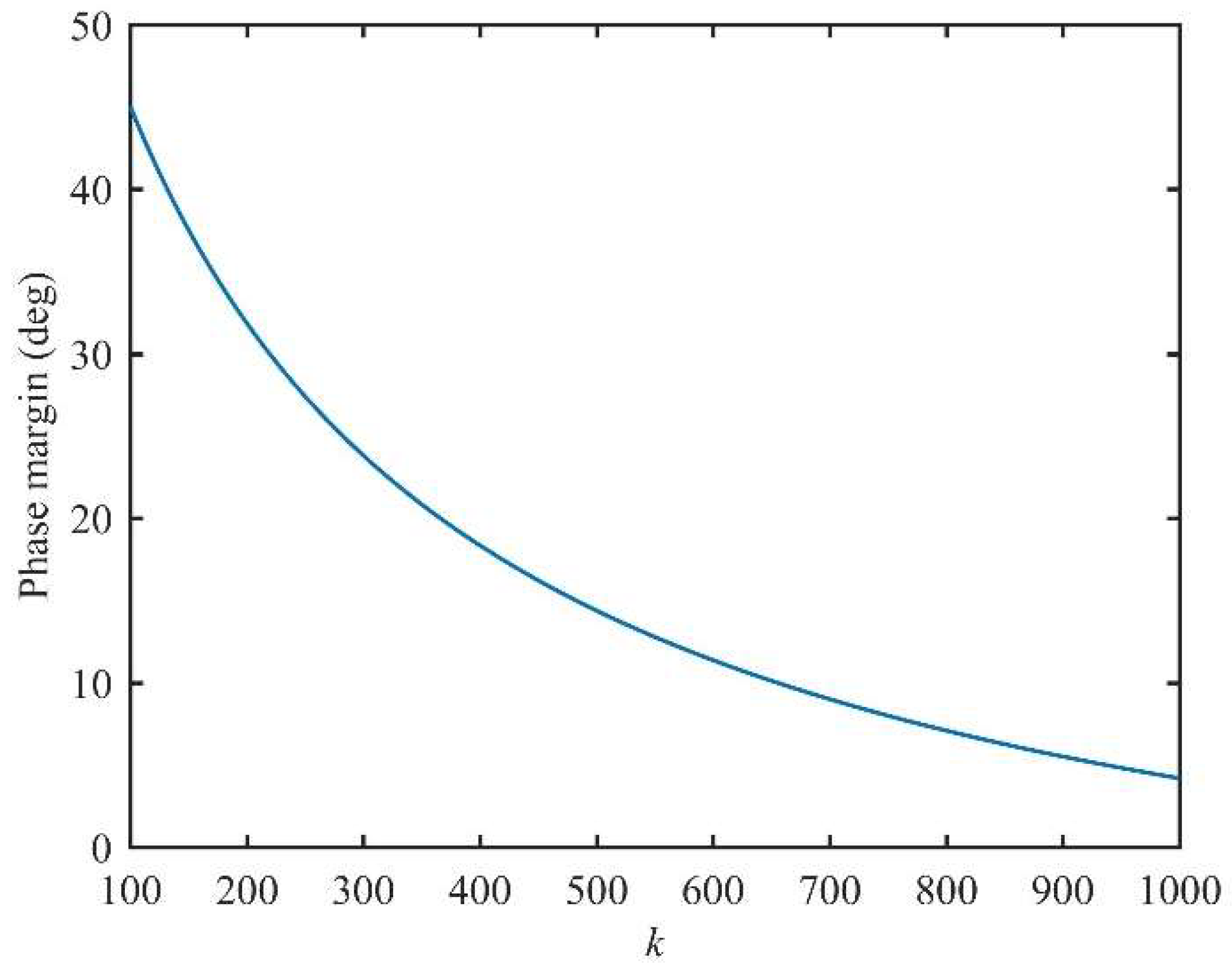
The phase margin as a function of k is also given in Figure 12. With k = 320 in this paper, the phase margin was 22.6°, which was sufficient to ensure the stability of the proposed PLL.
5. Experimental Results
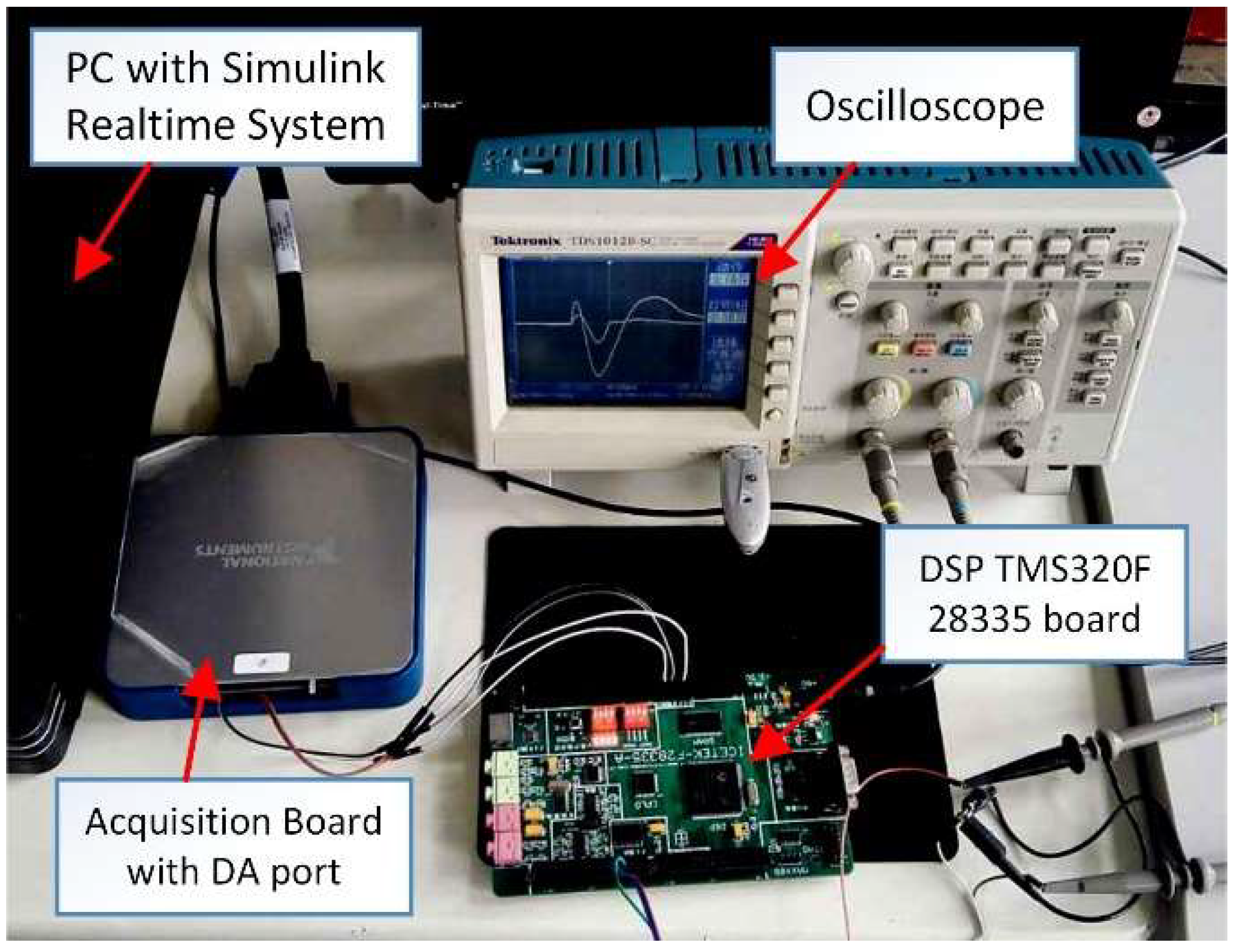
In this section, comparative experiments were carried out to examine the performance of the proposed PLL. The experimental setup is shown in Figure 13. The personal computer (PC) was linked with an acquisition board that acted as a programmable arbitrary waveform generator, to generate 50 Hz three-phase voltage signals. Using Matlab/Simulink/Realtime-workshop software, the three-phase grid voltage simulation model was downloaded onto the computer and was running on it in real time. Consequently, the three-phase voltage signals were output by an acquisition board to a digital signal processor (DSP, TMS320F28335). The proposed PLL was implemented in this DSP. After the computational operation in DSP, the estimated frequency and phase error of the proposed PLL were output by a digital-analytical (DA) conversion circuit of the DSP board, which was captured by an oscilloscope. The sampling frequency was 10 kHz.
Since the proposed PLL was based on a DSOGI and Quasi-type-1 PLL structure, a DSOGI-PLL with a PID controller (DSOGI-PLLPID) [27], and a QT1-PLL [26] were implemented in the comparative experiments. CNF-QT1-PLL, which was proposed by the authors of [22], was also evaluated in this section. The control parameters of these PLLs can be found in the literature mentioned above. MAFs that were used in these PLLs were with a fixed window length.
5.1. Phase Jump
A +40° phase jump happened to the three-phase grid voltages, as shown in Figure 14. Figure 15 illustrates the waveforms of PLLs under the phase jump condition. It can be seen from Figure 15b that the settling times of the proposed PLL and CNF-QT1-PLL were less than 20 ms. The waveforms of the estimated frequency also converged to 50 Hz in nearly 20 ms. However, the dynamic behaviors of QT1-PLL and DSOGI-PLLPID took more than 30 ms.
In accordance with the restrictive requirement of dynamic performance in many grid codes [28,29,30], the estimation of voltage phase and frequency should have been carried out in 25 ms. Consequently, QT1-PLL and DSOGI-PLLPID could not fulfill this requirement. It was not acceptable in some grid-connected applications such as low-voltage ride through.
5.2. Frequency Step Change
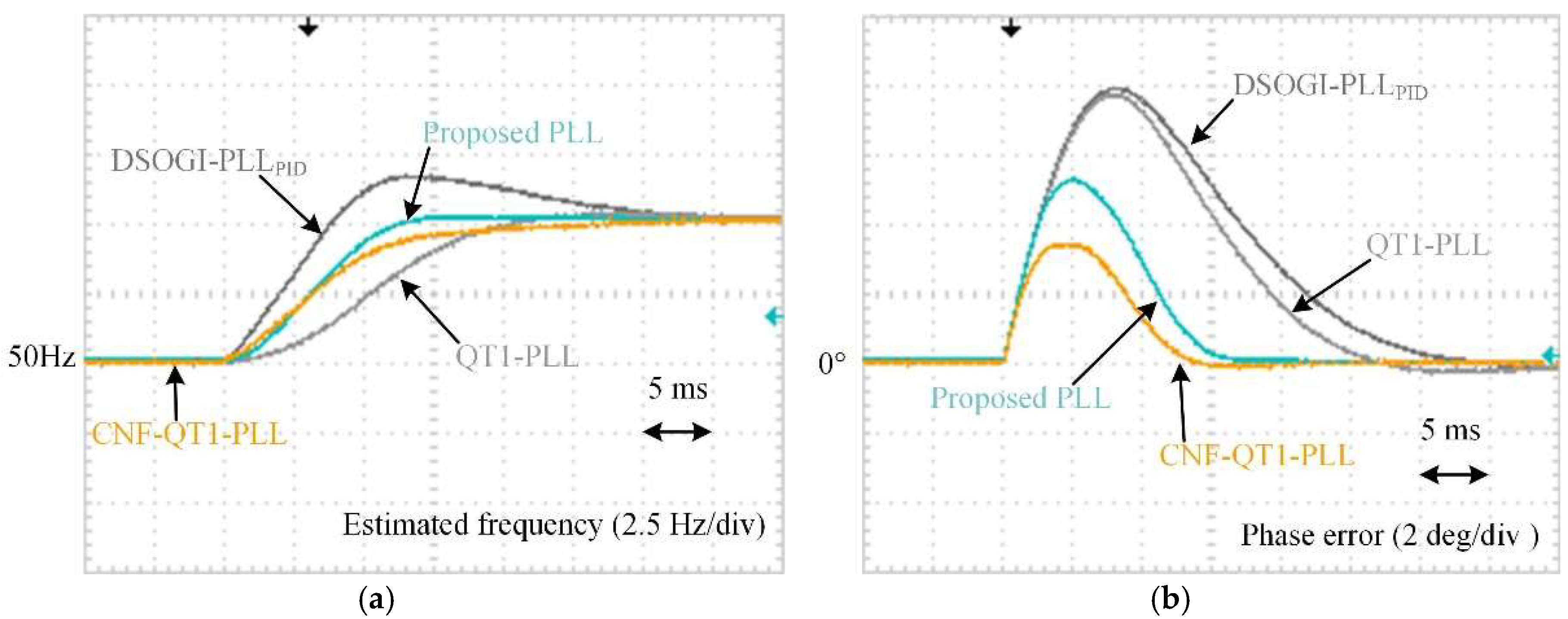
A +5 Hz frequency step change was implemented in grid voltages, as shown in Figure 16. The waveforms in response to the +5 Hz frequency step change are depicted in Figure 17. It is observed from Figure 17a that the proposed PLL could track the step change within 15 ms. CNF-QT1-PLL also provided a rapid transient response. The settling times of QT1-PLL and DSOGI-PLLPID in the estimated frequency were much longer. Figure 17b illustrates the phase errors of the PLLs. During the convergence time of the frequency step change, it took CNF-QT1-PLL less than 15 ms to converge the phase error to zero. The proposed PLL also provided a satisfactory performance. The convergence time of other methods were much longer.
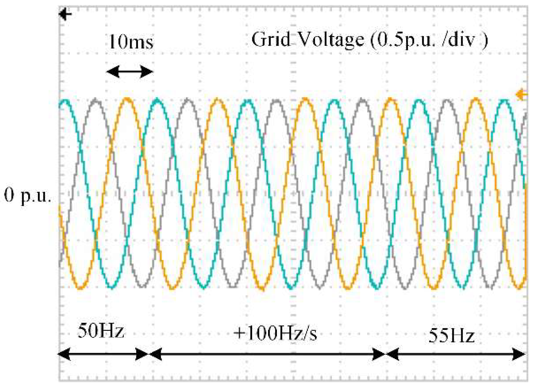
5.3. Frequency Ramp Change
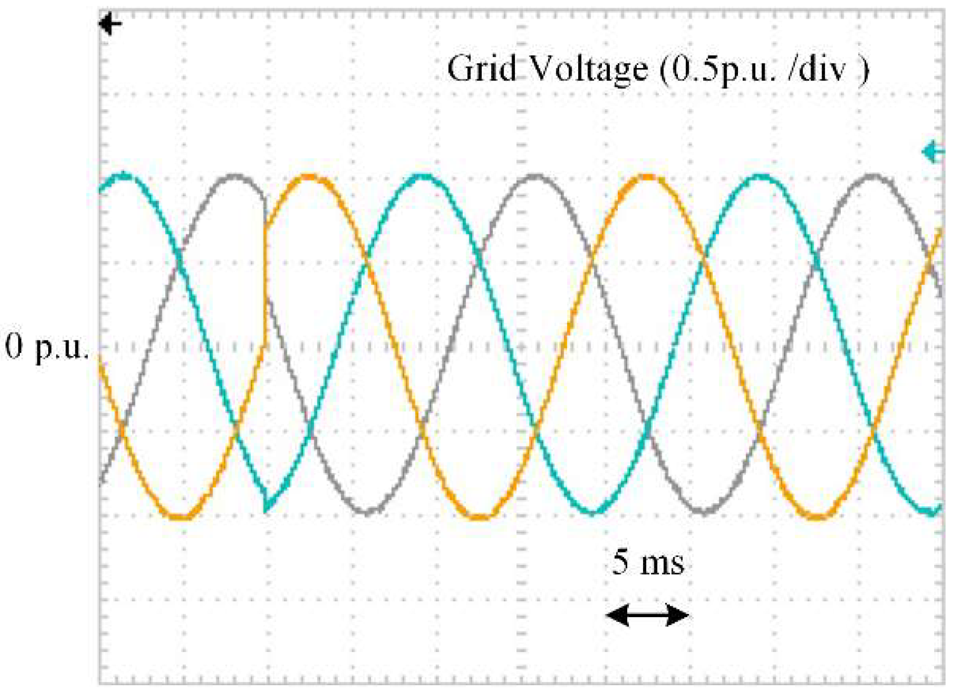
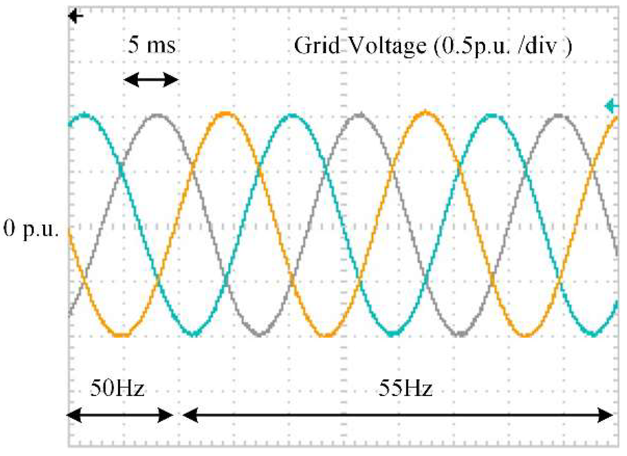
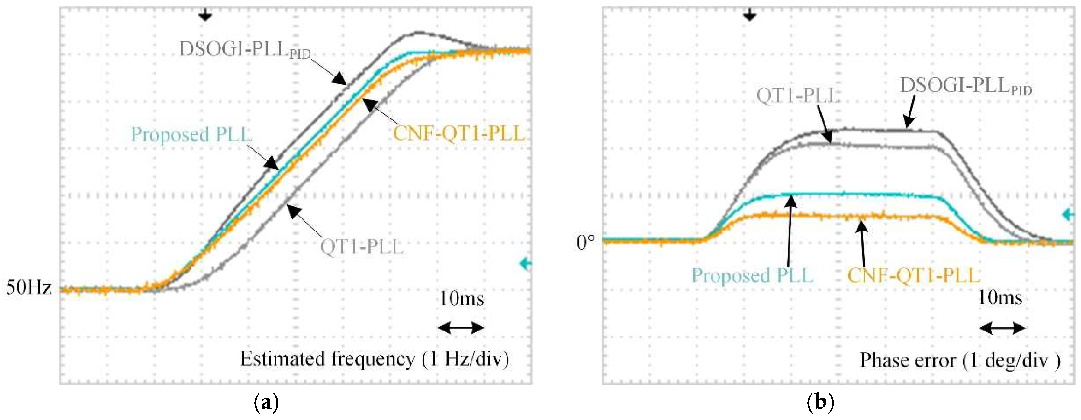
To examine the performance under a grid frequency drifting condition, a grid frequency was implemented to increase from 50 Hz to 55 Hz, by a +100 Hz/s ramp rising rate. The entire rising time took 50 ms. The waveforms of grid voltages are shown in Figure 18. As shown in Figure 19b, during the ramp rising procedure, CNF-QT1-PLL had the least phase error, of about 0.5°. The proposed PLL also provided a small enough phase error of 1°. Compared with DSOGI-PLLPID and QT1-PLL, two hybrid filtering techniques-based PLLs provided a more satisfactory phase-tracking performance.
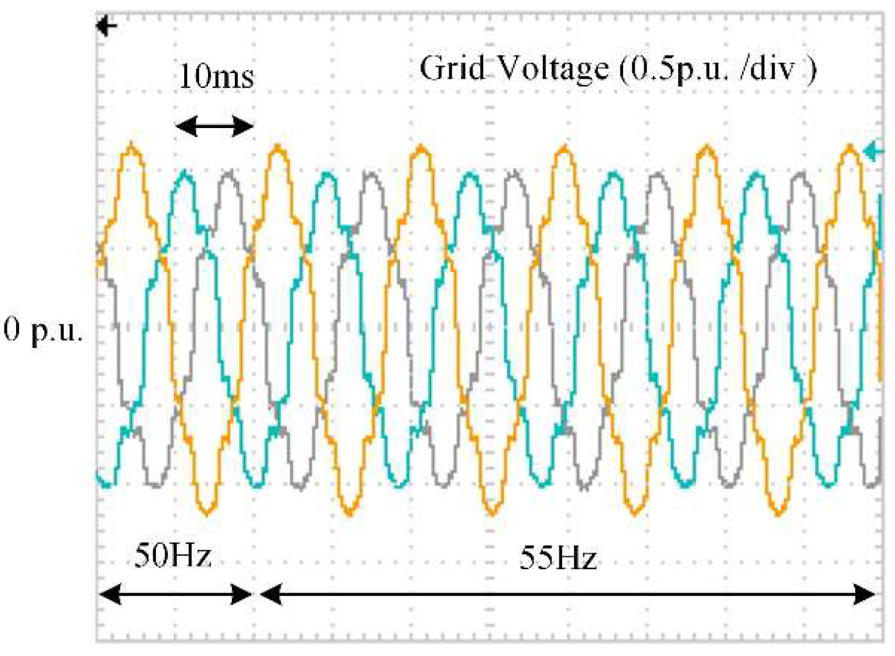
5.4. Unbalanced and Distorted Grid Voltages
The filtering capability of the proposed PLL was also examined under unbalanced and distorted grid voltages. To evaluate the phase tracking accuracy under both the nominal and off-nominal grid frequency conditions, a +5 Hz frequency step change was also implemented into the distorted grid voltages. The waveforms of the three-phase voltages are shown in Figure 20. Table 1 lists the parameters of grid voltages.
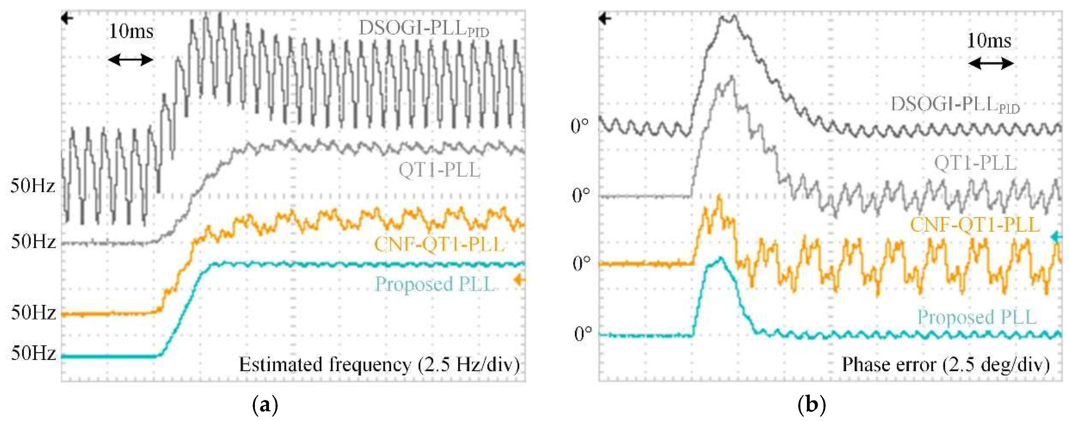
The waveforms of the estimated frequency and phase error are depicted in Figure 21. With the employment of MAF, all three MAF-based PLLs—QT1-PLL, CNF-QT1-PLL, and the proposed PLL—could eliminate disturbances completely when the grid frequency was 50 Hz. Since the filtering stage of DSOGI-PLLPID acted like a low-pass filter, it could only attenuate harmonic components. The estimated frequency error was much bigger than the others.
After a +5 Hz frequency step change happened, the performance of MAF-based PLLs tended to worsen, owing to the utilization of MAFs with a fixed window length. The tracking errors of the frequency and phase of CNF-QT1-PLL were much bigger than those in QT1-PLL and the proposed PLL, which were ±1 Hz and ±1.5°, respectively. The phase errors of QT1-PLL and CNF-QT1-PLL were getting even worse than those in DSOGI-PLL. However, the filtering capability was not affected by the frequency drift. The proposed PLL had the least tracking errors, which were less than ±0.5 Hz and ±0.5°.
5.5. Computational Burden
The computational burden was also compared among the tested PLLs. The number of operations required for digital implementation was listed in Table 2. The zero-order hold method was used for discrete implementation. Moreover, the Park and Clarke transformation was not included, since these operations were the same for all of the PLLs.
Observing Table 2, the computational load was much smaller than CNF-QT1-PLL’s load, which was also a hybrid filtering technique-based PLL. Although CNF-QT1-PLL could offer a good dynamic performance, the large amount of mathematical operations that were required in its filters made the PLL difficult to be realized on a chip board. By contrast, the proposed PLL was more convenient for the applications based on a micro-processor.
5.6. Summary
A summary of the experimental results is shown in Table 3. The performance of all four PLLs was assessed from the transient response and filtering capability.
In terms of the transient response, the proposed PLL provided the fastest dynamic response, which was less than one cycle under both the phase jump and frequency step change conditions. Compared with the other two PLLs, CNF-QT1-PLL also offered a satisfactory dynamic performance. These results were attributable to the combination of the hybrid filter and QT1-PLL structure. MAFs with a smaller Tω were another important factor. The settling times of the proposed PLL and CNF-QT1-PLL could meet most of the grid codes and requirement in practice.
In terms of filtering capability, the proposed PLL’s performance was better than other three PLLs’ performance. It provided a more robust tracking performance under the frequency drift and distorted grid conditions, since the frequency characteristic of its hybrid filtering technique (as shown in Figure 6) gave a more aggressive filtering capability than the other PLLs’ frequency characteristic. The tracking performance of CNF-QT1-PLL tended to worsen more under off-nominal grid frequency conditions. This was because the complex notch filters that were used in its hybrid filters were not frequency-adaptive. The high computational burden was another problem for its digital implementation.
6. Conclusions
Aiming at a rapid transient response, a hybrid filtering technique-based phase-locked loop is proposed in this paper to achieve an accurate phase-tracking performance, under both nominal and distorted grid conditions. By using DSOGI and MAFs with a narrowed window length, the time delay caused by the proposed hybrid filtering stage is drastically reduced. To achieve a fast, dynamic behavior under both the phase and frequency jump, a systematic parameter design procedure is also given in this paper. The effectiveness of the proposed PLL is confirmed through comparative experiments under various grid conditions. The experimental results indicate that the settling time of the proposed PLL is less than one cycle, which is shorter than most of the PLLs’ settling times. Its filtering capability is also better than other PLLs’ performance. With these positive properties, the proposed PLL can fulfill most of the grid synchronization requirements. Based on the proposed method, the studies in the future will be focused on the utilization of the proposed PLL in some specific applications.
Acknowledgments
This work was supported in part by the Application Technology Research and Engineering Demonstration Program of National Energy of China (NY20150303).
Author Contributions
Yunlu Li and Junyou Yang proposed the original idea and analyzed the experimental results. Yunlu Li and Haixin Wang built the experimental setup and performed the experiments. Yunlu Li wrote the full manuscript. Weichun Ge supervised the experiments. Yiming Ma did the simulation analysis.
Conflicts of Interest
The authors declare no conflicts of interest.
Nomenclature
The following nomenclatures are used in this manuscript:
| FFNS | Fundamental frequency negative sequence |
| MAF | Moving average filter |
| LPF | Low-pass filter |
| QT1-PLL | Quasi-type-1 PLL |
| DSOGI-PLL | Dual second-order generalized integrator-based PLL |
| CNF-QT1-PLL | Complex notch filter-based QT1-PLL |
| Tω | The window length of MAF |
| ωff | The fundamental angular frequency of grid voltage |
| Δω | The error of estimated angular frequency of grid voltage |
| The estimated angular frequency of grid voltage | |
| The estimated phase of grid voltage | |
| The value of phase jump | |
| vabc | Three-phase grid voltage |
| vα, vβ | The α-β-axis components of grid voltage after Clarke transformation |
| The direct axis components of vα, vβ | |
| The quadrature axis components of vα, vβ | |
| The α-β-axis components after prefiltering stage | |
| vd, vq | The d-q-axis voltage components after Park transformation |
| The d-q-axis voltage components after filtering processing | |
| q | The phase shift factor with 90° |
| ξ | Damping factor |
| kφ | Phase-compensator factor |
| k | The only control parameter in the proposed PLL |
| kp | Proportional factor in PI controller |
| ki | Integral factor in PI controller |
References
- Cao, Y.; Yu, J.; Xu, Y.; Li, Y.; Yu, J. An Efficient Phase-Locked Loop for Distorted Three-Phase Systems. Energies 2017, 10, 280. [Google Scholar] [CrossRef]
- Hui, N.; Wang, D.; Li, Y. An Efficient Hybrid Filter-Based Phase-Locked Loop under Adverse Grid Conditions. Energies 2018, 11, 703. [Google Scholar] [CrossRef]
- Ameli, A.; Bahrami, S.; Khazaeli, F.; Haghifam, M. A Multiobjective Particle Swarm Optimization for Sizing and Placement of DGs from DG Owner’s and Distribution Company’s Viewpoints. IEEE Trans. Power Deliv. 2014, 29, 1831–1840. [Google Scholar] [CrossRef]
- Heydari, J.; Tajer, A. Quickest Localization of Anomalies in Power Grids: A Stochastic Graphical Framework. IEEE Trans. Smart Grid. 2017. [Google Scholar] [CrossRef]
- Ahmadzadeh, M.; Mortazavi, S.; Saniei, M. Applying the Taguchi Method for Investigating the Phase-Locked Loop Dynamics Affected by Hybrid Storage System Parameters. Energies 2018, 11, 226. [Google Scholar] [CrossRef]
- Luo, W.; Jiang, J.; Liu, H. Frequency-Adaptive Modified Comb-Filter-Based Phase-Locked Loop for a Doubly-Fed Adjustable-Speed Pumped-Storage Hydropower Plant under Distorted Grid Conditions. Energies 2017, 10, 737. [Google Scholar] [CrossRef]
- Golestan, S.; Guerrero, J.; Vasquez, J. Three-Phase PLLs: A Review of Recent Advances. IEEE Trans. Power Electron. 2017, 32, 1894–1907. [Google Scholar] [CrossRef]
- Hadjidemetriou, L.; Yang, D.; Kyriakides, E.; Blaabjerg, F. A Synchronization Scheme for Single-Phase Grid-Tied Inverters under Harmonic Distortion and Grid Disturbances. IEEE Trans. Power Electron. 2017, 32, 2784–2793. [Google Scholar] [CrossRef]
- Hadjidemetriou, L.; Kyriakides, E.; Blaabjerg, F. An Adaptive Tuning Mechanism for Phase-Locked Loop Algorithm for Faster Time Performance of Interconnected Renewable Energy Sources. IEEE Trans. Ind. Appl. 2015, 51, 1792–1804. [Google Scholar] [CrossRef]
- Hadjidemetriou, L.; Kyriakides, E.; Blaabjerg, F. A Robust Synchronization to Enhance the Power Quality of Renewable Energy Systems. IEEE Trans. Ind. Electron. 2015, 62, 4858–4868. [Google Scholar] [CrossRef]
- Luna, A.; Rocabert, J.; Candela, J.; Hermoso, J.; Teodorescu, R.; Blaabjerg, F.; Rodriguez, P. Grid Voltage Synchronization for Distributed Generation Systems under Grid Fault Conditions. IEEE Trans. Ind. Appl. 2015, 51, 3414–3425. [Google Scholar] [CrossRef]
- Rodriguez, P.; Teodorescu, R.; Candela, I.; Timbus, A.; Liserre, M.; Blaabjerg, F. New Positive-Sequence Voltage Detector for Grid Synchronization of Power Converters under Faulty Grid Conditions. In Proceedings of the 2006 37th IEEE Power Electronics Specialists Conference, Jeju, Korea, 18–22 June 2006; pp. 1–7. [Google Scholar]
- Guo, X.; Wu, W.; Chen, Z. Multiple-Complex Coefficient-Filter-Based Phase-Locked Loop and Synchronization Technique for Three-Phase Grid-Interfaced Converters in Distributed Utility Networks. IEEE Trans. Ind. Electron. 2011, 58, 1194–1204. [Google Scholar] [CrossRef]
- Xiao, P.; Corzine, K.; Venayagamoorthy, G. Multiple Reference Frame-Based Control of Three-Phase PWM Boost Rectifiers under Unbalanced and Distorted Input Conditions. IEEE Trans. Power Electron. 2008, 23, 2006–2017. [Google Scholar] [CrossRef]
- Rodriguez, P.; Pou, J.; Bergas, J.; Candela, J.; Burgos, R.; Boroyevich, D. Decoupled Double Synchronous Reference Frame PLL for Power Converters Control. IEEE Trans. Power Electron. 2007, 22, 584–592. [Google Scholar] [CrossRef]
- Golestan, S.; Monfared, M.; Freijedo, F. Design-Oriented Study of Advanced Synchronous Reference Frame Phase-Locked Loops. IEEE Trans. Power Electron. 2013, 28, 765–778. [Google Scholar] [CrossRef]
- Golestan, S.; Ramezani, M.; Guerrero, J.; Freijedo, F.; Monfared, M. Moving Average Filter Based Phase-Locked Loops: Performance Analysis and Design Guidelines. IEEE Trans. Power Electron. 2014, 29, 2750–2763. [Google Scholar] [CrossRef]
- Wang, J.; Liang, J.; Gao, F.; Zhang, L.; Wang, Z. A Method to Improve the Dynamic Performance of Moving Average Filter-Based PLL. IEEE Trans. Power Electron. 2015, 30, 5978–5990. [Google Scholar] [CrossRef]
- Tsili, M.; Papathanassiou, S. A Review of Grid Code Technical Requirements for Wind Farms. IET Renew. Power Gener. 2009, 3, 308–332. [Google Scholar] [CrossRef]
- PO-12.3. In Requisitos de Respuesta Frente a Huecos de Tension de las Instalaciones Eolicas; Comisión Nacional de Energía: Madrid, Spain, 2006.
- Golestan, S.; Guerrero, J.; Abusorrah, A.; Al-Turki, Y. Hybrid Synchronous/Stationary Reference-Frame-Filtering-Based PLL. IEEE Trans. Ind. Electron. 2015, 62, 5018–5022. [Google Scholar] [CrossRef]
- Li, Y.; Wang, D.; Han, W.; Sen, T.; Guo, X. Performance Improvement of Quasi-Type-1 PLL by Using a Complex Notch Filter. IEEE Access 2016, 4, 6272–6282. [Google Scholar] [CrossRef]
- Rani, B.; Aravind, C.; Ilango, G.; Nafamani, C. A Three Phase PLL with a Dynamic Feed Forward Frequency Estimator for Synchronization of Grid Connected Converters under Wide Frequency Variations. Int. J. Electr. Power Energy Syst. 2012, 41, 63–70. [Google Scholar] [CrossRef]
- Geng, H.; Sun, J.; Xiao, S.; Yang, G. Modeling and Implementation of an All Digital Phase-Locked-Loop for Grid-Voltage Phase Detection. IEEE Trans. Ind. Inform. 2013, 9, 772–780. [Google Scholar] [CrossRef]
- Golestan, S.; Ramezani, M.; Guerrero, J. An Analysis of the PLLs with Secondary Control Path. IEEE Trans. Ind. Electron. 2014, 61, 4824–4828. [Google Scholar] [CrossRef]
- Golestan, S.; Freijedo, F.; Vidal, A.; Guerrero, J.; Doval-Gandoy, J. A Quasi-Type-1 Phase-Locked Loop Structure. IEEE Trans. Power Electron. 2014, 29, 6264–6270. [Google Scholar] [CrossRef]
- Golestan, S.; Monfared, M.; Freijedo, F.; Guerrero, J. Performance Improvement of a Prefiltered Synchronous-Reference-Frame PLL by Using a PID-Type Loop Filter. IEEE Trans. Ind. Electron. 2014, 61, 3469–3479. [Google Scholar] [CrossRef]
- On, E. Grid Code-High and Extra High Voltage; On Netz Gmbh: Bayreuth, Germany, 2006; Available online: http://www.pvupscale.org/IMG/pdf/D4_2_DE_annex_A-3_EON_HV_grid__connection_requirements_ENENARHS2006de.pdf (accessed on 16 April 2018).
- IEEE Std. IEEE Standard for Interconnecting Distributed Resources with Electric Power Systems; IEEE: New York, NY, USA, 2003. [Google Scholar]
- The Grid Code: Revision 31; National Grid Electricity Transmission: Warwick, UK, 2008.
Figure 1.
Schematic of grid connected power converter system with a phase-locked loop (PLL). PCC—point of common coupling; GPC—grid-connected power converter; DC—direct current; AC—alternative current; PWM—pulse width modulation; LC—inductance and capacitance filter.
Figure 1.
Schematic of grid connected power converter system with a phase-locked loop (PLL). PCC—point of common coupling; GPC—grid-connected power converter; DC—direct current; AC—alternative current; PWM—pulse width modulation; LC—inductance and capacitance filter.

Figure 2.
Block diagrams of the three PLLs. (a) synchronous-reference frame phase-locked loop (SRF-PLL); (b) moving average filter phase-locked loop (MAF-PLL); and (c) quasi-type-1 phase-locked loop (QT1-PLL).
Figure 2.
Block diagrams of the three PLLs. (a) synchronous-reference frame phase-locked loop (SRF-PLL); (b) moving average filter phase-locked loop (MAF-PLL); and (c) quasi-type-1 phase-locked loop (QT1-PLL).

Figure 3.
Bode diagrams of the three PLLs: QT1-PLL (solid lines), SRF-PLL (dashed lines), and MAF-PLL (dotted lines).
Figure 3.
Bode diagrams of the three PLLs: QT1-PLL (solid lines), SRF-PLL (dashed lines), and MAF-PLL (dotted lines).

Figure 4.
Block diagram of the proposed PLL. DSOGI—dual second-order generalized integrator.

Figure 5.
The block diagram of second-order generalized integrators (SOGI).

Figure 6.
The bode plot of DSOGI.

Figure 7.
The bode plot of the filtering technique in the proposed PLL (solid line), complex notch filter-based QT1-PLL (CNF-QT1-PLL) (dashed line), and QT1-PLL (dotted line).
Figure 7.
The bode plot of the filtering technique in the proposed PLL (solid line), complex notch filter-based QT1-PLL (CNF-QT1-PLL) (dashed line), and QT1-PLL (dotted line).

Figure 8.
Small-signal model of the proposed PLL. LPF—low-pass filter.

Figure 9.
Performance comparison between the proposed PLL (solid lines) and its small-signal model (dashed lines) with different control parameters (k).
Figure 9.
Performance comparison between the proposed PLL (solid lines) and its small-signal model (dashed lines) with different control parameters (k).

Figure 10.
The equivalent small-signal model of the proposed PLL.

Figure 11.
The relationship between k and 2% settling time under phase jump (solid line) and frequency step change (dashed line).
Figure 11.
The relationship between k and 2% settling time under phase jump (solid line) and frequency step change (dashed line).

Figure 12.
Phase margin as a function of k.

Figure 13.
Photograph of experimental setup. DSP—digital signal processor.

Figure 14.
Grid voltage under a +40° phase jump condition.

Figure 15.
The experimental results when grid voltage undergoes a +40° phase jump. (a) Estimated frequency and (b) phase error.
Figure 15.
The experimental results when grid voltage undergoes a +40° phase jump. (a) Estimated frequency and (b) phase error.

Figure 16.
Grid voltage under a +5 Hz frequency step change.

Figure 17.
The experimental results when grid voltage undergoes a +5 Hz frequency step change. (a) Estimated frequency and (b) phase error.
Figure 17.
The experimental results when grid voltage undergoes a +5 Hz frequency step change. (a) Estimated frequency and (b) phase error.

Figure 18.
Grid voltage under a frequency ramp change of +100 Hz/s.

Figure 19.
The experimental results when grid voltage undergoes a frequency ramp change of +100 Hz/s. (a) Estimated frequency and (b) phase error.
Figure 19.
The experimental results when grid voltage undergoes a frequency ramp change of +100 Hz/s. (a) Estimated frequency and (b) phase error.

Figure 20.
Grid voltage under unbalanced and distorted condition.

Figure 21.
The experimental results when grid voltage is unbalanced and distorted. (a) Estimated frequency and (b) phase error.
Figure 21.
The experimental results when grid voltage is unbalanced and distorted. (a) Estimated frequency and (b) phase error.


Table 1.
Parameters of grid voltages.
| Voltage Component | Title 2 |
|---|---|
| Fundamental positive sequence (+1st order) | 1 |
| Fundamental negative sequence (−1st order) | 0.1 |
| 5th harmonic negative sequence (−5th order) | 0.1 |
| 7th harmonic positive sequence (+7th order) | 0.05 |
| 11th harmonic negative sequence (−11th order) | 0.05 |
| 13th harmonic positive sequence (+13th order) | 0.05 |
Table 2.
Number of operation required for digital implementation. PLL—phase-locked loop; QT1-PLL—quasi-type-1 PLL; CNF-QT1-PLL—complex notch filter-based QT1-PLL; DSOGI-PLLPID—dual second-order generalized integrator-based PLL with a PID controller.
Table 2.
Number of operation required for digital implementation. PLL—phase-locked loop; QT1-PLL—quasi-type-1 PLL; CNF-QT1-PLL—complex notch filter-based QT1-PLL; DSOGI-PLLPID—dual second-order generalized integrator-based PLL with a PID controller.
| Header | +/− | ×/÷ | Memory Size |
|---|---|---|---|
| Proposed PLL | 8 | 10 | 69 |
| CNF-QT1-PLL | 48 | 23 | 83 |
| QT1-PLL | 6 | 7 | 203 |
| DSOGI-PLLPID | 8 | 10 | 6 |
Table 3.
Summary of experimental results.
| Grid Conditions | DSOGI-PLLPID | QT1-PLL | CNF-QT1-PLL | Proposed PLL |
|---|---|---|---|---|
| +40° phase jump | - | - | - | - |
| 2% settling time | ≈1.81 cycles | ≈1.5 cycles | ≈0.84 cycles | ≈0.79 cycles |
| Peak phase error | 11.4° | 12.2° | 13.2° | 14.3° |
| Peak frequency deviation | 16.1 Hz | 8.9 Hz | 9.7 Hz | 9.5 Hz |
| +5 Hz frequency step change | - | - | - | - |
| 2% settling time of estimated frequency | ≈1.74 cycles | ≈1.7 cycles | ≈1.6 cycles | ≈0.7 cycles |
| Peak phase error | 7.9° | 7.6° | 3.2° | 5.1° |
| Peak frequency deviation | 1.6 Hz (32%) | 0 Hz (0%) | - | - |
| +100 Hz/s frequency ramp change | - | - | - | - |
| Phase error | 2.3° | 1.9° | 0.58° | 1.1° |
| Unbalanced and distortion | - | - | - | - |
| Peak-to-peak phase error | 0.7° | 2° | 3.8° | 0.4° |
| Peak-to-peak frequency error | 4.5 Hz | 0.6 Hz | 1.2 Hz | 0.15 Hz |
| Computational burden | low | low | high | low |
© 2018 by the authors. Licensee MDPI, Basel, Switzerland. This article is an open access article distributed under the terms and conditions of the Creative Commons Attribution (CC BY) license (http://creativecommons.org/licenses/by/4.0/).
Share and Cite
MDPI and ACS Style
Li, Y.; Yang, J.; Wang, H.; Ge, W.; Ma, Y. A Hybrid Filtering Technique-Based PLL Targeting Fast and Robust Tracking Performance under Distorted Grid Conditions. Energies 2018, 11, 973. https://0-doi-org.brum.beds.ac.uk/10.3390/en11040973
AMA Style
Li Y, Yang J, Wang H, Ge W, Ma Y. A Hybrid Filtering Technique-Based PLL Targeting Fast and Robust Tracking Performance under Distorted Grid Conditions. Energies. 2018; 11(4):973. https://0-doi-org.brum.beds.ac.uk/10.3390/en11040973
Chicago/Turabian StyleLi, Yunlu, Junyou Yang, Haixin Wang, Weichun Ge, and Yiming Ma. 2018. "A Hybrid Filtering Technique-Based PLL Targeting Fast and Robust Tracking Performance under Distorted Grid Conditions" Energies 11, no. 4: 973. https://0-doi-org.brum.beds.ac.uk/10.3390/en11040973
Note that from the first issue of 2016, this journal uses article numbers instead of page numbers. See further details here.