Analysis of IEC 61850-9-2LE Measured Values Using a Neural Network


Brno University of Technology, Technicka 12, 616 00 Brno, Czech Republic
*
Author to whom correspondence should be addressed.
Energies 2019, 12(9), 1618; https://0-doi-org.brum.beds.ac.uk/10.3390/en12091618
Submission received: 27 February 2019
/
Revised: 23 April 2019
/
Accepted: 26 April 2019
/
Published: 28 April 2019
(This article belongs to the Special Issue Data Analytics in Energy Systems)
Abstract
:Process bus communication has an important role to digitalize substations. The IEC 61850-9-2 standard specifies the requirements to transmit digital data over Ethernet networks. The paper analyses the impact of IEC 61850-9-2LE on physical protections with (analog-digital) input data of voltage and current. With the increased interaction between physical devices and communication components, the test proposes a communication analysis for a substation with the conventional method (analog input) and digital method based on the IEC 61850 standard. The use of IEC 61850 as the basis for smart grids includes the use of merging units (MUs) and deployment of relays based on microprocessors. The paper analyses the merging unit’s functions for relays using IEC 61850-9-2LE. The proposed method defines the sampled measured values source and analysis of the traffic. By using neural net pattern recognition that solves the pattern recognition problem, a relation between the inputs (number of samples/ms—interval time between the packets) and the source of the data is found. The benefit of this approach is to reduce the time to test the merging unit by getting the feedback from the merging unit and using the neural network to get the data structure of the publisher IED. Tests examine the GOOSE message and performance using the IEC standard based on a network traffic perspective.
Keywords:
IEC61850; SMV; sampled value; GOOSE; Ethernet; SVScout; delay time; IED; time synchronization; machine learning; ROCs1. Introduction
Substations in energy systems use intelligent electronic devices (IEDs) that can share data in real-time, in order to use and share these data quickly and efficiently among the substation devices [1]. Sharing data must be standardized as a communication standard. The IEC 61850 standard unites the structure, requirements, and communication specifications that can be implemented during sharing of data among IEDs, the first announcement of the cooperation and creates a platform between the substation automation system (SAS) and the substations (IEC 61850 2003) [2]. IEC 61850-9-2 specifies that the transmission of sampled measured values (SMVs) over an Ethernet network is located in the second layer (Ethernet layer) in an OSI system, using sampled values generated by merging units of IEDs or individual merging units, instrument transformers [3]. The implementation of IEC 61850-9-2 depends on the dataset specifications such as (time synchronization, sample counts, and interval time). Four currents and voltages are included into the IEC 68150-9-2 packets.
Some studies have presented practical implementations of IEC 61850 that included a large number of IEDs; these studies explored the challenges coming from this technical evolution and used equipment from multiple vendors to achieve interoperability. The references cited below discuss the requirements of interoperable distributed functions and distinguish the differences between MV and HV substations regarding IEC61850 implementation [4,5].
Reference [6] proposes solutions to integrate IEC 61850 communication with the meters and their communication interfaces. This work implemented a complete smart grid realized on the basis of IEC standards. As further discussed in this work, the number of integrated units that can be used for monitoring and control purposes in the power system is quite small, and that means that there is also need for developed techniques for data handling to achieve realize smart distribution [7].
Research work has been presented in [8] analyzing the various communications options for scalable deployment of smart grid services. As stated in [8], the authors used the software-defined utility (SDU) concept to obtain automated management of the smart grid.
Reference [9] focused on the communications capabilities in traditional protections with the ability to use other technologies like WiFi and 3G for signal communication in real time. Several research articles [10,11] have proposed methods to develop self-healing functionality in smart grids using IEC 61850.
Reference [12] proposed a laboratory test bed for comparing the performance of digital, hybrid and traditional substations. The experiment focused on the hard in the loop test with traditional current and voltage-operated protection relays and with sampled measured values according to IEC 61850-9-2LE. The comparison found that the relay protection function performance is very similar to that of classical substations, with the advantage of the data transmission in digital form.
Reference [13] focused on the configuration of IEC 61850 GOOSE service for easy implementation with electric protection systems; the authors proposed an algorithm to achieve full implementation of the IEC 61850 instead of the hard wired network connection.
Reference [14] focused on the reliability analysis of the cyber-physical interface matrix (CPIM) methodology. The test calculated the impact of the physical device failure and the communication devices failures.
This paper contains the following sections:
- Section 2: Time synchronization over a process bus. This section contains the test structure with the devices used during the test. It contains the GPS parameters and initial test of the signal which generated from the GPS.
- Section 3: The IEC 61850 sampled measured values testing. This section contains the sampled values test with the OMICRON device and the test structure and sampled values directions.
- Section 4: The timing analysis of sampled values streams. This section contains the result of the measurement of the OMICRON merging unit and physical relays. (CMC-publisher, IED-publisher- 2x IED-subscriber) when time synchronization is applied, however, the interval time is around 240 µs with the local clock of the publisher IED or CMC merging unit, the interval time is around 230 µs with the global clock (GPS is applied).
- Section 5: Generic Object Oriented Substation Events (GOOSE). A GOOSE trip signal is sent from the publisher IED to the subscriber IED. This test found that when the GOOSE message is sent to the receiver IED (tripping signal), the signal is duplicated four times with a size of 147 bytes per packet, the average interval time between the packets was practically constant from the first to the fourth packets (278 µs) and the average interval between the fourth and the fifth packet was 102 ms.
- Section 6: Machine learning. By machine learning, we found a link between two parameters (number of samples/ms – interval time) and used to determine the publisher. The inputs and the target provided to the network and the algorithm breaks up the data for test sets (training 70%—validation 15%—testing 15%), the best validation was in epoch 23.
1.1. Impact of IEC 61850 on Substation Operations
The main goals to implement IEC 61850 standard [15] are as follows:
- Increase the power quality, reducing the copper wires that are plugged into the IEDs and acheiving faster response to short circuit faults.
- The IEC 61850 standard provides the interoperability between IEDs from various manufacturers and offers a friendly configuration that can be implemented at a site without external support.
- Reducing the cost of operation and maintenance in the substations.
- This standard provides secure and fast data transmission among IEDs and substation devices.
- The IEC 61850 functionality is flexible and easy to implement by using the tools properly.
The challenges to implementing the IEC 61850 [15] are processing a huge amount of real-time data and replacing some parts of substations to create a better environment to implement IEC 61850.
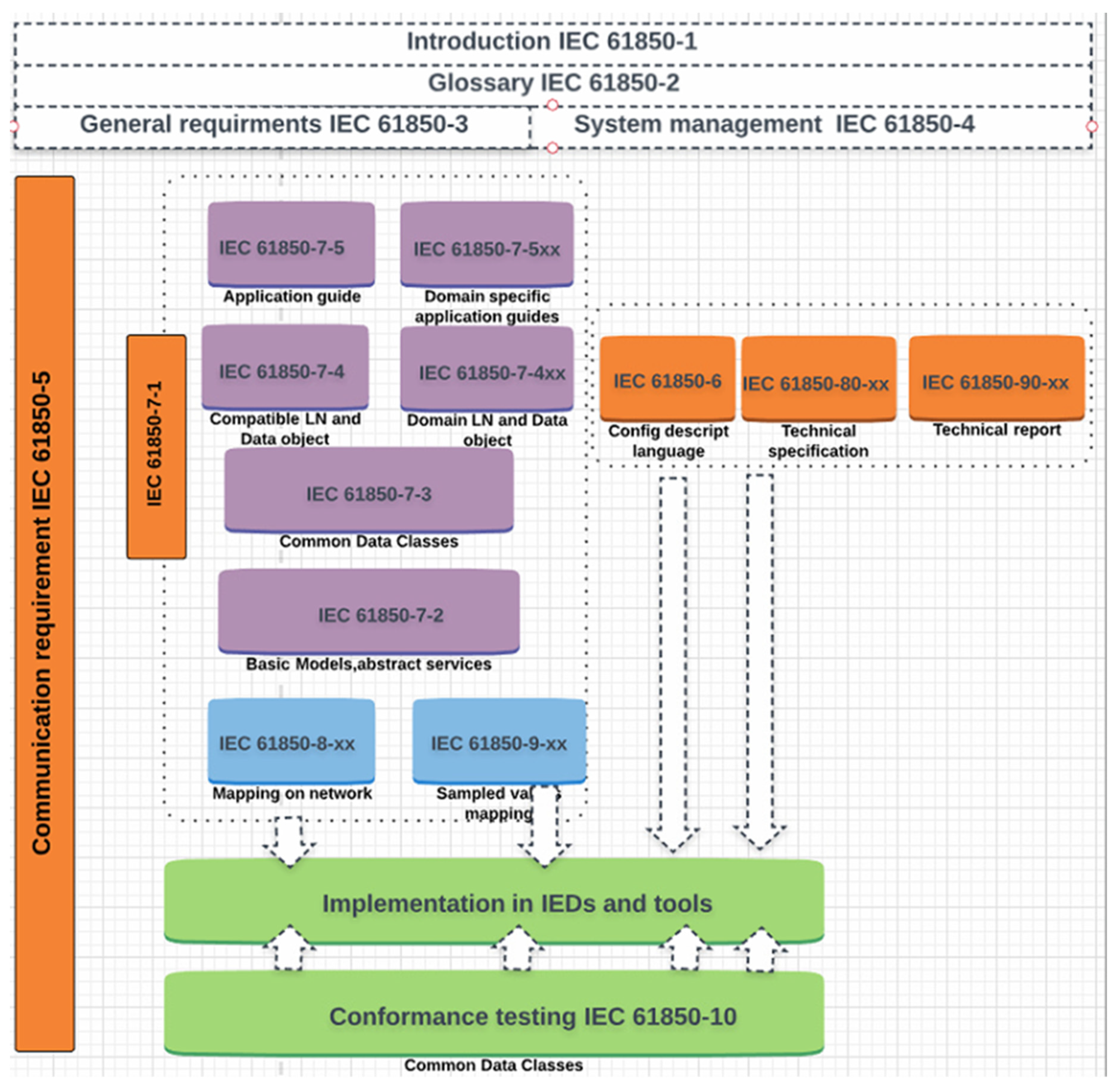
The IEC 61850 structure includes 14 parts, as shown in Figure 1.
The IEC 61850 standard offers a data model that can replace the physical devices by the logical devices. In this way IEC 61850 is able to virtualize to all devices in the power system. Each logical device (LD) has logical nodes (LNs) that provides the functions of the devices. These functions are called “distributed functions” in SAS, and the three main rules to implement the distributed functions are:
- The IEC 61850 configuration should follow the performance requirements.
- The communication interface between IEDs and the system should follow the IEC 61850 standards communication fundamentals.
- Establish the communications between devices by mean transfer data between IEDs and the power system among the SAS.
The structure of the data model in the IEC 61850 standard is virtual (data object, logical device, logical node), although, it represents real data that are used by the energy system (monitoring, protection and automation systems) [11]. IEC 61850 offers various features that cover all aspects of the substations measurements, as follows [11]:
- Data characterization such as sampling frequency, sampling counts, and time synchronization.
- Communication specification that can be summarized as a generic object oriented substation event (GOOSE), manufacturing message specification (MMS), SMV, and Ethernet communication.
- The data structures and data objects’ services.
According to the specification of the IEC 61850 can be summarized as follows:
- Definition and determine how to access the structure for the data’s abstract communication services interface (ACSI) and the configuration of the communication solution and compatible protocols.
- Standardizing the output data from IEDs and categories the sharing of data between GOOSE and SMV orders
- The IEDs and network communications are implemented using eXtendable Markup Language (XML).
1.2. The IEC 61850 Information System
Logical nodes (LNs) are the most important part of the IEC 61850 hierarchical model. This model is designed to provide the way for implementation the interoperability among IEDs within the power system, the model represents the actual devices in the power system as logical devices LDs) that are plugged into logical nodes. The physical devices contain distributed functions that are responsible for exchanging data; each LN is linked with a function in the physical device [4].
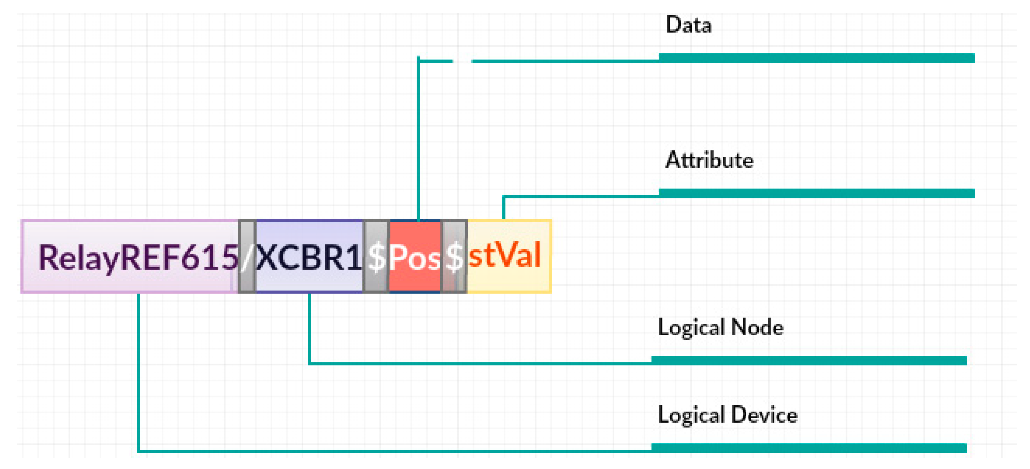
The data model explains the hierarchy of IEC 61850, the definition of the logical device and server is specified by the administrator. Depending on the data model structure, the data of substation operations can be assigned to one of these logical nodes, for instance, the measurements function group begins with “M” and the protection function group begins with “P”. In Figure 2 from left to right, the device name is the first part and the logic node (LN) is the second part, the attribute that represents a function is the third part, “st” represents the status attributes, “Pos” represents the position of the circuit breaker and “Val” represents the value of the status.
2. Time Synchronization over a Process Bus
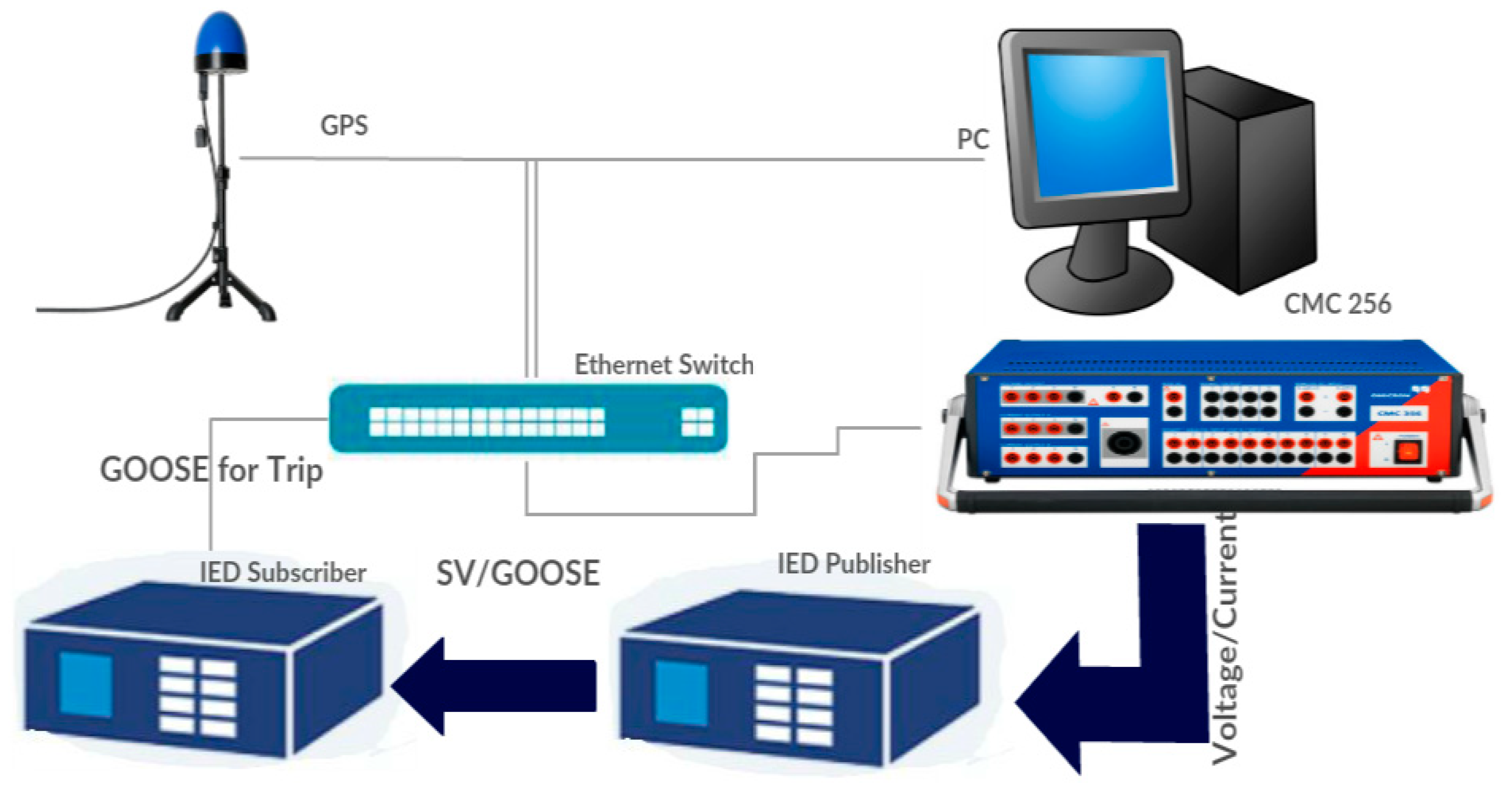
Time synchronization is an important element in sampled value applications due to the problems that can be caused in case the time synchronization is lost due to phase shifts, maloperation or wrong tripping. In the laboratory during implementation the SMV IEDs configuration, the time synchronization can be done by the IEDs-publisher. In this way the IED-subscriber will follow and get the same phase error limit. In case of using several merging units connected together and sharing data among the power system, the time source according to IEC 61869 is required. This time source will be a global area clock, however, a local area clock cannot match the time in the global area clock. There are various methods that can be implemented to achieve the time synchronization in the whole testing system and between the merging units such as master-slave architecture for clock distribution (IEEE 1588) precision time protocol (PTP). IEEE 1588 is used to achieve the time synchronization because the IEDs are adaptable to this method and offered high accuracy time synchronization. According to IEC 61869, the GPS or time source is sharing the time over the process bus side by side with sampled values. The configuration of the time synchronization of IEDs is shown in Figure 3. In IEDs, time synchronization is enabled by using synch source (IEEE 1588—slave), IED-subscriber (Figure 3) shows a synch accuracy of 23 ns.
More precisely, the sampled values and PTP are using the same network cable; however, a cut in the Ethernet cable can cause SMV and PTP transfer failure. The relation between sampled values and time synchronization is called SmpSynch. This attribute is an indicator of time source loss, moreover, SmpSynch gives details about the time source (GPS) and the sampled values sources (IED-publisher). Table 1 provides the settings of the GPS data and the timing accuracy that are used to achieve the time synchronization in our network [4].
PTP Clock Types in Time Synchronization
The time synchronized is required to get more accurate measurements and implement the Peer-to-Peer (PTP) protocol. Grandmaster is synchronized with an external source such as a CMGPS 588 (GPS) controlled time reference. The synchronization unit is an antenna-integrated GPS that works as PTP grandmaster clock according to IEEE 1588. Ordinary clock reads can be performed from IEDs or CMC 256 plus. This test requires an advanced Ethernet switch (Hirschmann). Table 2 lists the GPS status and the timing protocol that was implemented during the experiments (the synch interval between two synchronized messages is 1 s, and announcing the timeout and losing the time synchronization takes 3 s.
3. The IEC 61850 Sampled Measured Values Testing
The test includes three stages. The first one sends sampled measured values from one IED to another (publisher to subscriber). An Omicron CMC 256 plus is used to generate analog voltage and current signals, the signals are transferred to the CMLIB A to send it using Ethernet cables to the IED port (IED-publisher). As connection box for low-level signals a CMLIB A is used for connecting the low signal outputs of a CMC for measurement or controlling purposes. The CMLIB A set (VEHZ1105) includes the CMLIB A box (VEHZ1101) and the 16 pole LEMO cable (VEHK0003) [16]. As shown in Figure 6 and Table 3.
The analog signal is converted to a digital signal in the IED (A/D converter). The IED-publisher publishes the sampled value signal according to the standard IEC 61850 with 80 samples/cycle in a 50 Hz system. The subscriber IED is receiving the digital signal SMV and reacts according to the signal and the configuration of the IED. SVScout software is used to visualize sampled values and subscribes to the SMV streams from multiple merging units and shows the waveforms. An Omicron CMC 256 simulator is used to simulate the current transformer (CT) and voltage transformer (VT) signals as shown in Figure 7 [10].
3.1. Sampled Values Test
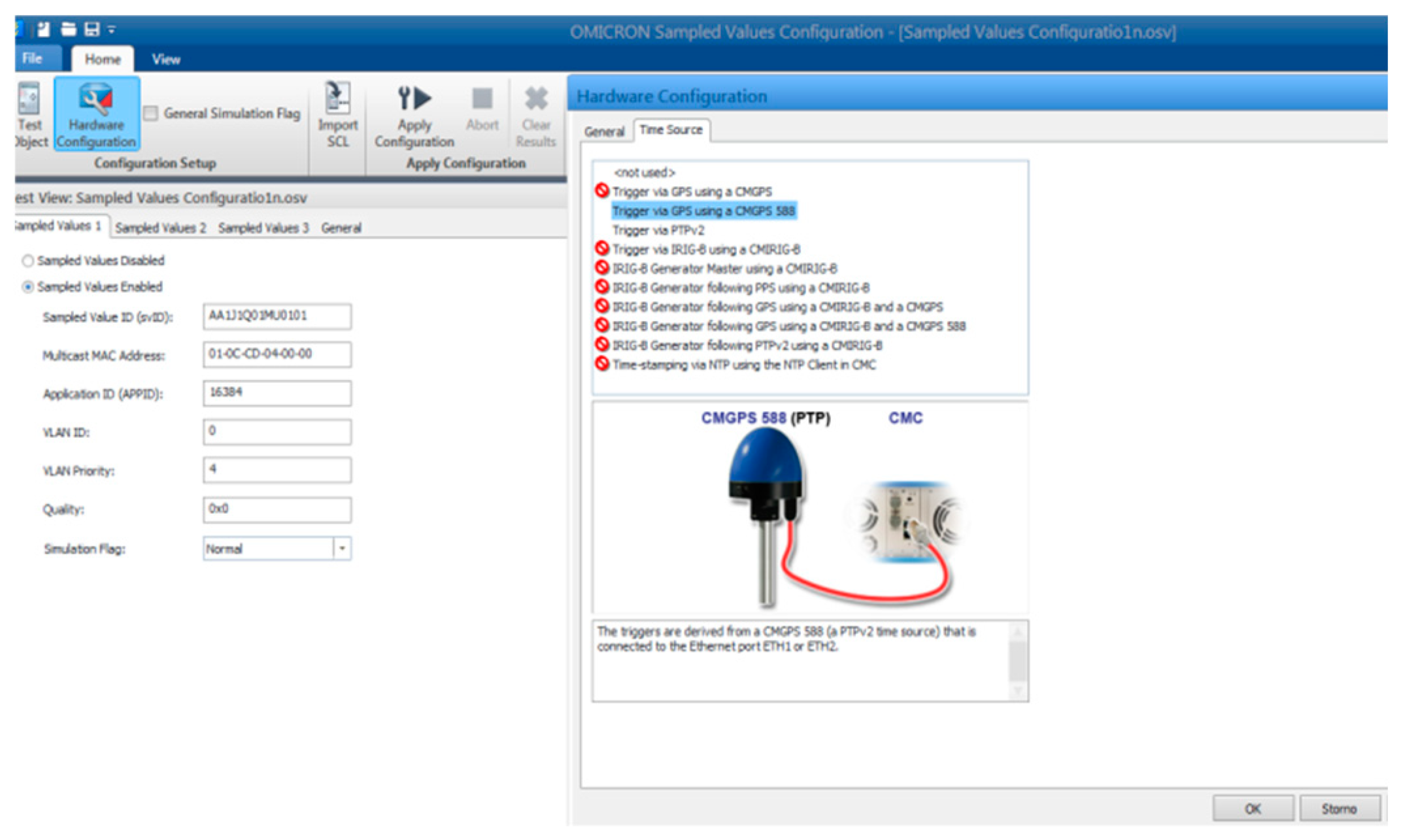
The sampled values test can be implemented to simulate the merging unit of the IED-publisher. The configuration of the test is required to import the substation configuration language (SCL) file of the publisher IED, moreover, the sampled values test tests the IEC 61850 9-2 LE process bus. It is able to generate up to three sampled values streams in the test set. In order to publish the sampled values it is important to set the analog voltages and currents generated at the voltage and current outputs of the test set as shown in Figure 8.
3.2. SVScout Software
This is a tool for visualizing the IEC 61850 sampled values; it provides the possibility to test the digital protection that is working with IEC 61850 sampled values. It used to receive, view, process and save sampled values to the implementation guideline of the UCA International Users Group IEC 61869-9 standard. The data packets can be obtained from many sources at the same time and the timing analysis for those data streams could be performed.
4. The Timing Analysis of Sampled Values Streams
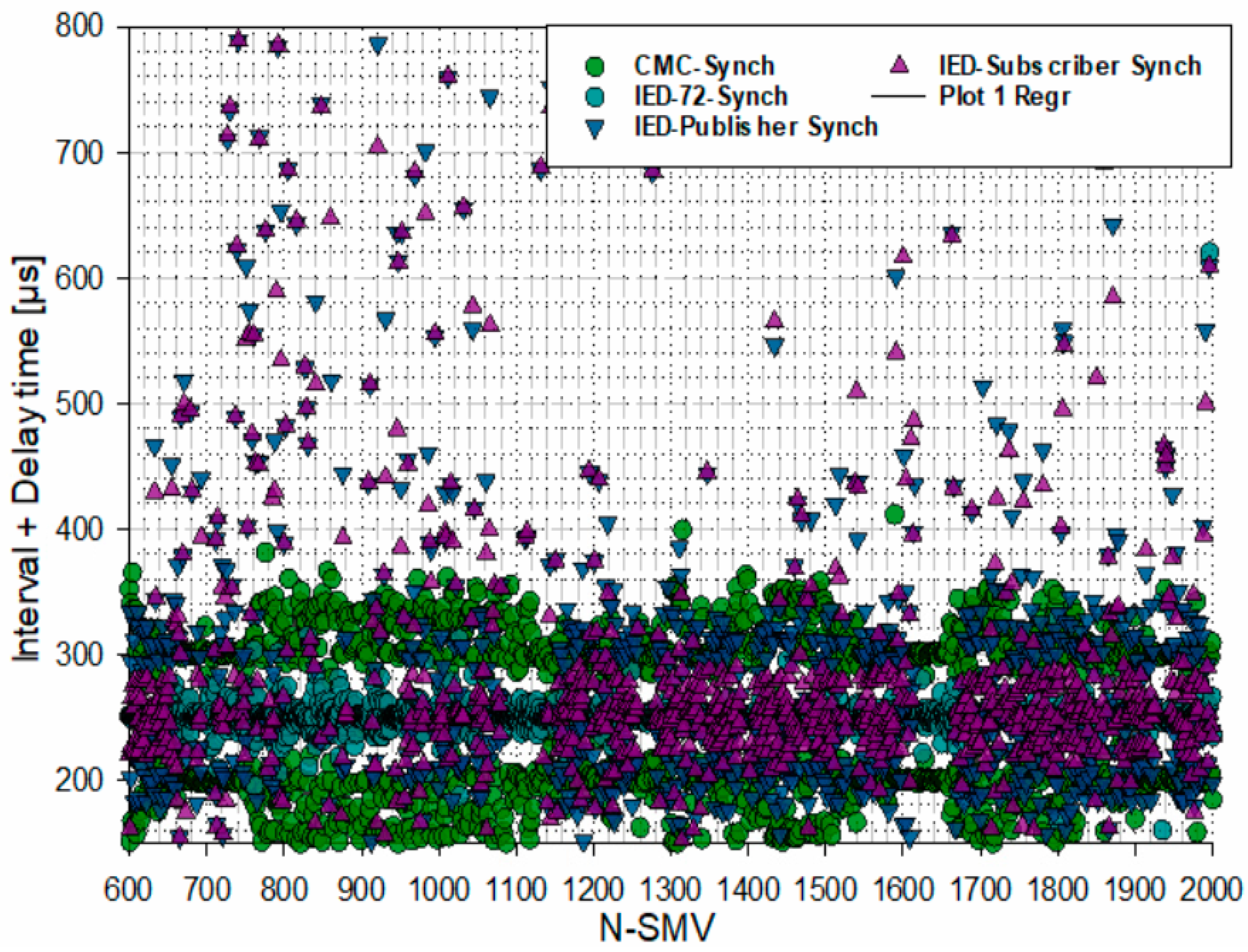
In order to understand the data acquisition of sampled values, the comparison of sampled values between IED_MU and CMC_MU with no time synchronization of the CMC 256, the measurements of the merging unit are implemented in the laboratory, the CMC 256 is configured to publish the sampled values to simulate the merging unit of the IED merging unit by importing the SCL file of the IED-publisher, thus, the CMC Omicron provides the ability to publish the sampled measured values and the comparison with the IED merging unite offering a way to analyze the time as shown in Figure 9. The interval between two packets can be calculated as T = 1/4000 = 250 ms, more than that, the delay time is accompanied by the interval as shown in Table 4. The IED-publisher publishes the sampled values and the time synchronized as the local clock (master clock) of the publisher IED [8].
Time Display and Time References
Time display formats in Wireshark can be explained according to the following steps:
- While packets are captured, each packet is timestamped. Each capture file includes these timestamps which is important for later analysis.
- According to RFC 2544 testing methodology, RFC 2544 requires the standard frame sizes (128, 256, 512, and 1280) bytes.
Brno University of Technology performed tests to measure the roundtrip latency on the fiber optic cable (Ethernet transmission) [17], finding the following results:
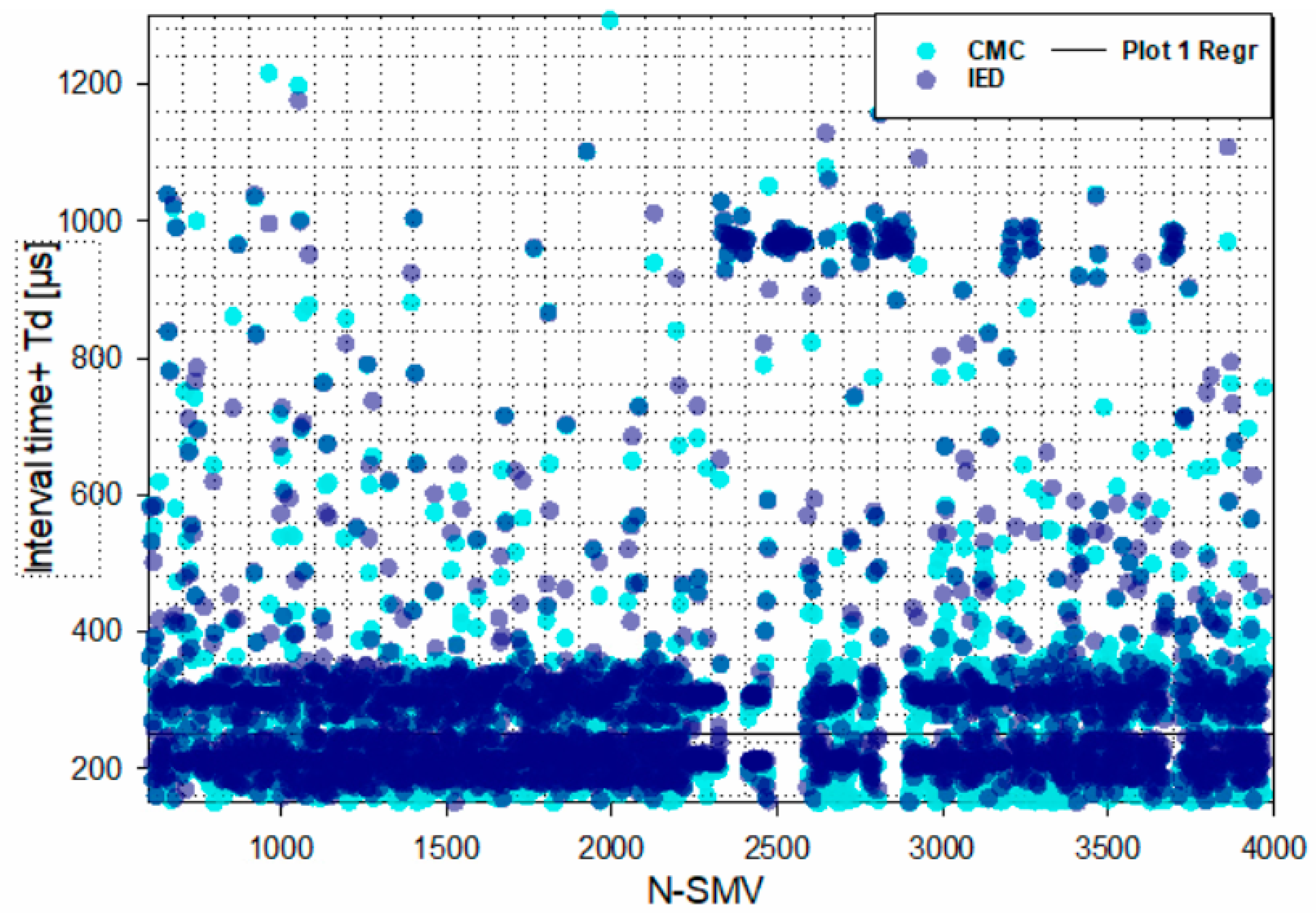
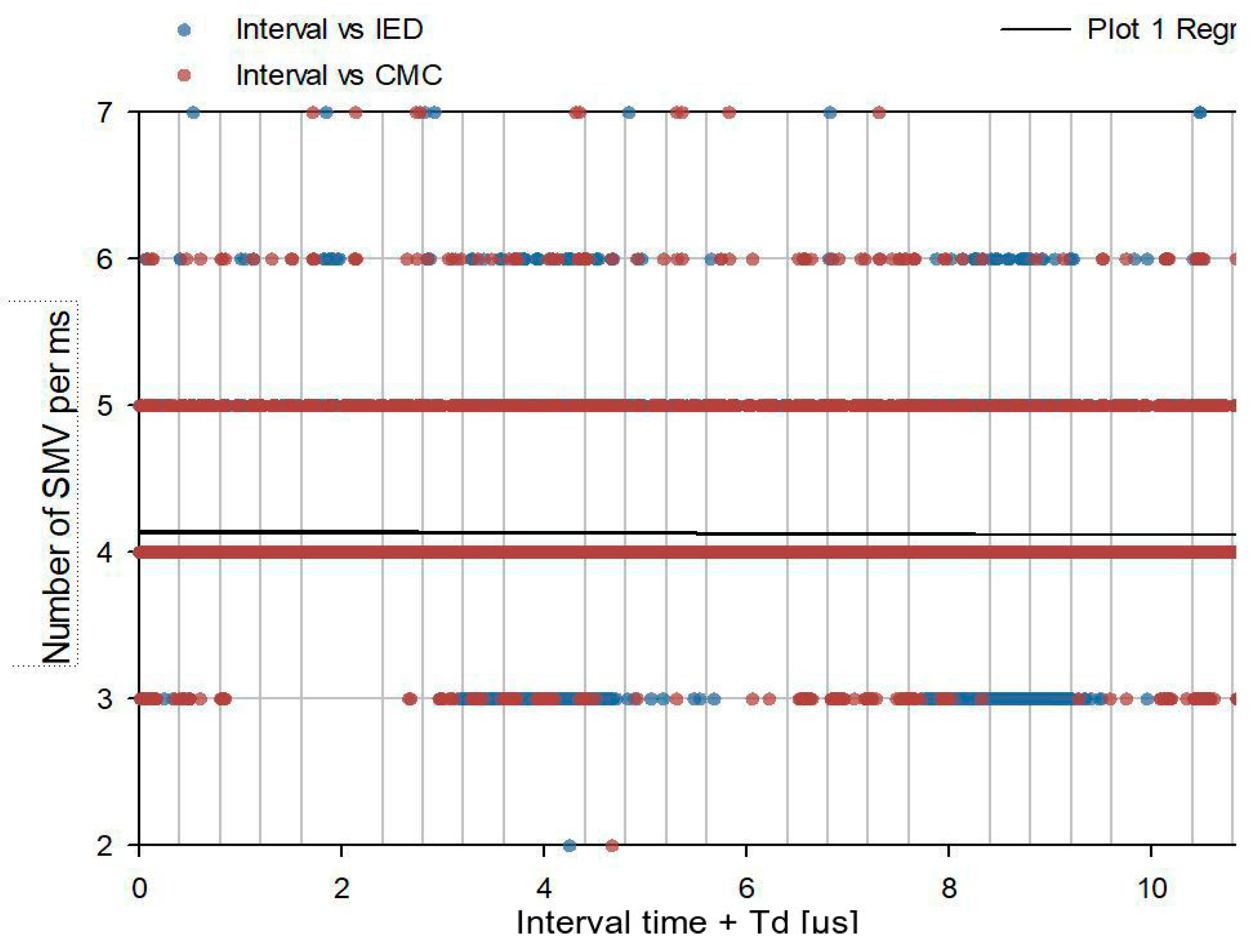
Figure 10 presents the number of packet per millisecond. The figure shows the comparison between the merging units of the IED and CMC, the number of packets is proximity around four packets for each merging units, with some high number of packets for the IED-publisher and a low number of packets for the IED publisher. The CMC hold still the number of packets to four packets per ms. Experiments offer the possibility to make a comparison between two merging units, the physical relay merging unit and the simulated merging unit (CMC). The figure shows that regression of the samples is 230 µs in case of time synchronization applied to both merging units. The simulated merging unit shows a constant interval of time between the packets as shown in the figure, however, the merging unit of a physical IED in 4000 samples showed that the interval time is not constant, the sender IED sends packets with 126 bytes length and the subscriber IED sends packets with 122 bytes length.
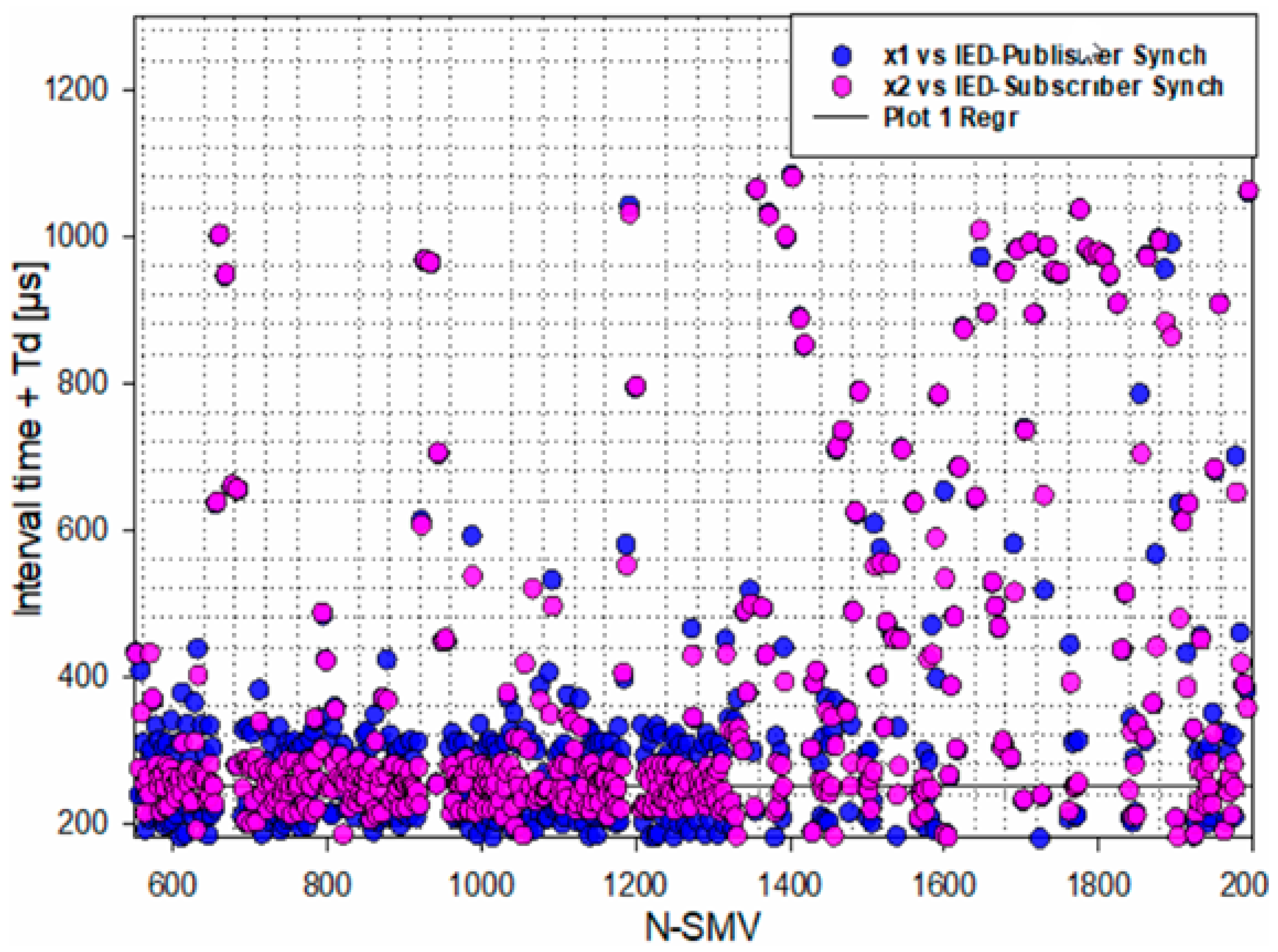
Figure 11 shows the SMV packets between the publisher and subscriber of physical relays, the regression of the interval time is around 240 µs, the current and voltage signals are plugged in the IED, the publisher converted them to a digital form and sent them to the IED-subscriber [9].
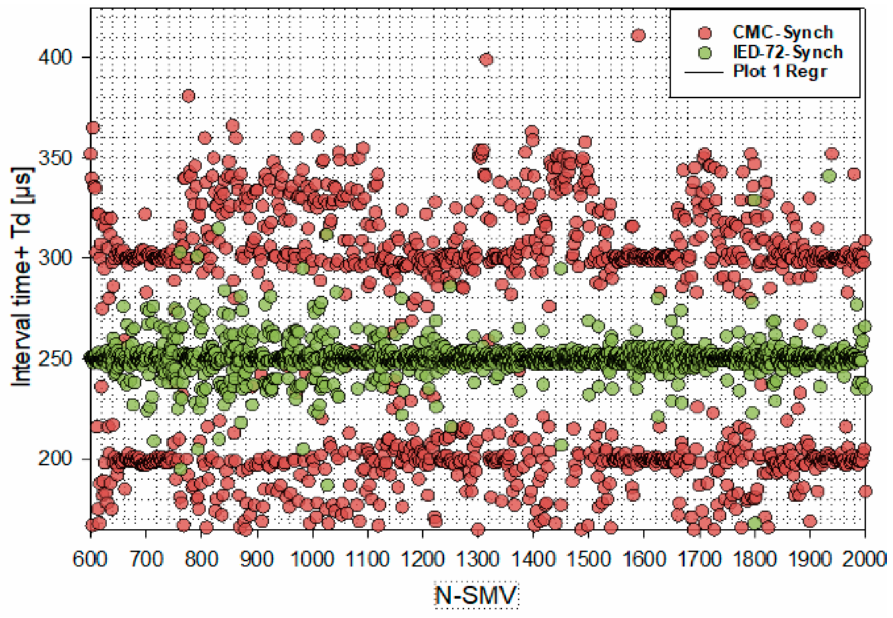
In Figure 12, CMC is the publisher of SMV that is synchronized by the global clock (GPS), IED-72 is the receiver or subscriber of the SMVs, according to the measurements the publisher is sending the packets and waits for the subscriber to send a confirmation of acceptance of the packets which explains why there are small delay times from the publisher in this case [18].
In order to make the study clear, Wireshark wasused to capture the sampled values streams and packet delay time or the time between two following streams calculated in two cases, the first one when two IEDs are connected and are an IED-publisher and IED-subscriber with time synchronization. The second case is when the CMC Omicron 256 plus merging unit is connected through the Ethernet switch to the IED-subscriber. The difference between no synchronization and synchronized time is that the IEDs start to synchronize with the master grand clock (GPS).
The sample count is an important parameter to determine and view the links between the synchronization time and the sampled value measurements. In order to explain and verify the sample count, the measurement is implemented with different cases, first with the SMV from merging units of IED without time synchronization, second with the SMV from IED merging units with time synchronization. The third count is the SMV from the CMC Omicron merging unit without the time synchronization; the fourth count is the SMV from the merging unit of the CMC Omicron with time synchronization. The last count is the count of the samples values of the merging unit of CMC Omicron and IED in parallel with time synchronization as shown in Figure 13.
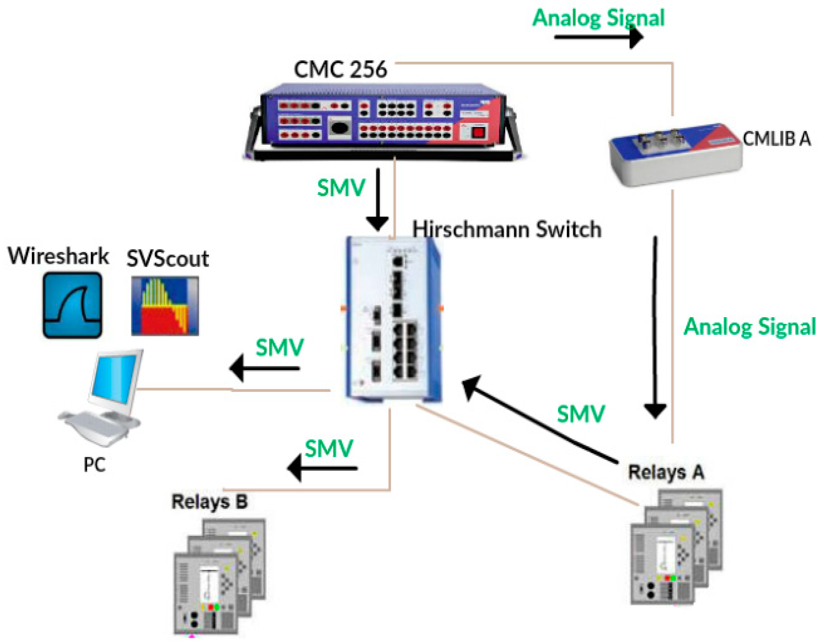
The SMV packets from different sources can be analyzed by using the Wireshark software which is the tool used to capture the network traffic. SMV streams of merging units of IEDs or the CMC Omicron can be monitored and analyses can be done to measure the interval time between different packets from the merging units and eventually Wireshark offers the way to show the dropped or lost packets. Figure 7 offers a diagram or schematic of a test, where the Omicron CMC acts as a current and voltage source (CT transformer sensor, VT transformer sensor), two IEDs are connected and is configured to be a publisher of sampled values and the second IED is a SMV subscriber, a network capture tool (Wireshark, SVScout), CMC Omicron merging unit, eventually using GPS time synchronization as shown in Figure 3. The IEC 61850-9-2 standard determines the sampled frequency which is based on the power system frequency that according to the IEC 61850 standard is 4 kHz for a 50 Hz system, or 4.8 kHz for a 60 Hz one. For one unit stream, the interval between one packet and the following packet is between (200 µs to 250 µs). SVScout is the tool which is used in the graphical display that allows one to verify the published measured values and compare the samples from other merging units. The SVScout enabling the way to compare the streams from merging units and save the report in comtrade format. The delay of packets can be caused by many reasons: lack of numerical precision, merging unit accuracy and sample count rate [19]. The calculation of communication capacity shown in Table 5.
Available communication capacity for two SMV publishers in a parallel redundancy protocol (PRP) network [19] is given by:
Available communication capacity for two SMV publishers in a high-availability seamless redundancy (HSR) network [13] is:
5. Generic Object Oriented Substation Events (GOOSE)
IEC 61850 GOOSE, with its fast transfer characteristics within a network environment (<3 ms as defined by the standard), is now being widely used for protection purposes in place of conventional dedicated wiring. As described, this brings great benefits to the user since the needed dedicated wiring can be reduced. The test provides the ability to implement the IEC 61850 standard (SMV, GOOSE).
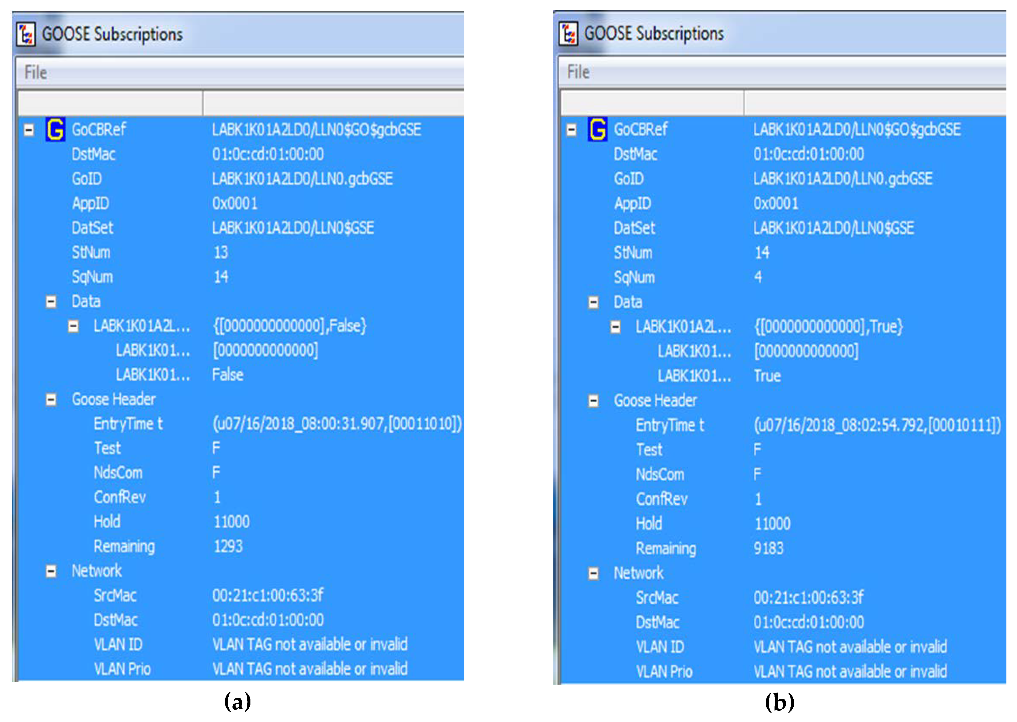
The sampled measured values and GOOSE message published and the GOOSE trip signal is sent from the publisher IED to the subscriber IED. Figure 14a shows the subscriber interface before sending the GOOSE message (trip signal) and Figure 14b shows the trip signal sent and the input changed to true. In order to capture the GOOSE message that was sent from one IED to another, we use the IEDScout software that provides the sniffer for GOOSE messages and provides the interface to monitor the signal status. PCM 600 is the tool used to configure the protection relay and add digital data transfer functions. The PCM 600 provides the way to start the IEC 61850 communications through process bus communication or GOOSE.
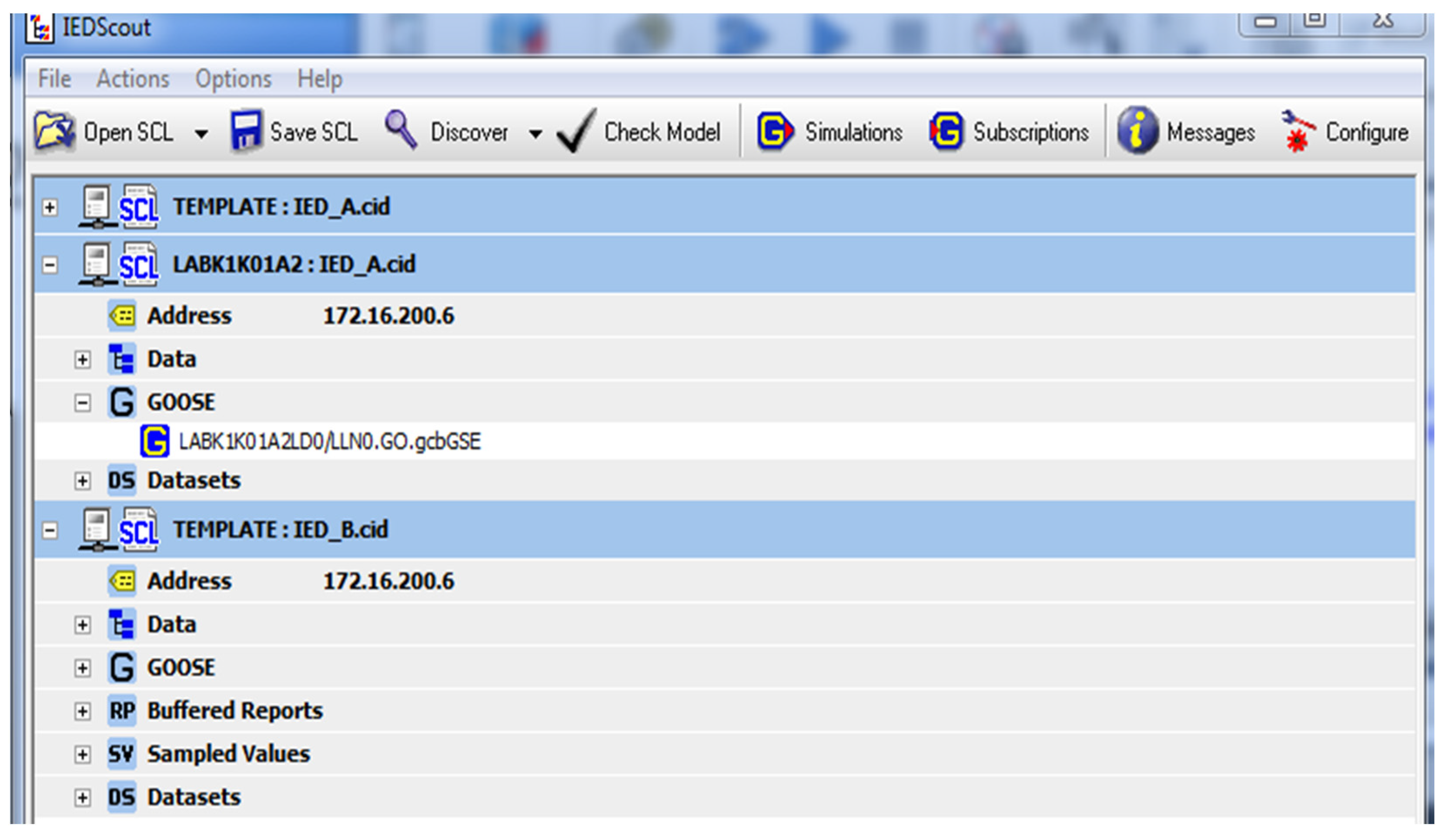
The IEDScout tool provides the ability to map the GOOSE message and the dataset of all the IEDs in the network, in order to implement interoperability between the devices on SAS. Figure 15 shows the IEDScout tool and the dataset of the IEDs that are part of the configuration (publisher, subscriber) and the interface of this tool imports the Configured IED Description (CID) file and linked the IEDs according to the configuration as shown in Figure 15.
The GOOSE message measurements show that the same packet is duplicated five times with a length of 147 bytes per message, the interval between GOOSE messages is not constant, conversely, the interval begins to be longer than the first interval between the first and second packet of GOOSE messages, as shown in Figure 16.
The interval starts at 278 µs and the last interval ends at 102.66 milliseconds, and the same thing occurs for four different GOOSE messages. Eventually, the GOOSE messages have been removed from the network and the network protocol analyzer. The configuration of GOOSE communication is implemented in the subscriber and publisher IEDs, the GOOSE message is sent from publisher to subscriber once the voltage or current is higher than the limit [20].
6. Machine Learning
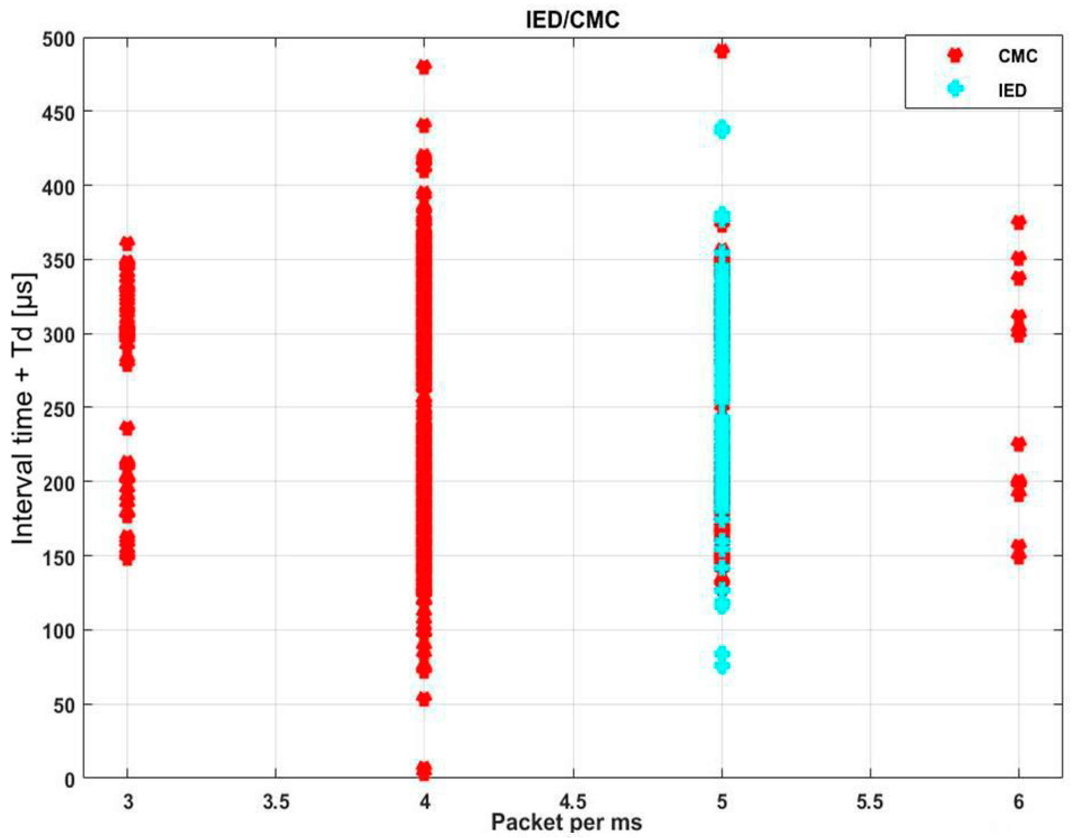
Machine learning techniques are used for power quantity analysis and decision-making tasks (accurate forecasting, comparing different machine learning techniques). The data description of the model can be summarized by the IED merging unit and CMC merging unit. A Substation Configuration Language (SCL) file is exported from the IED-publisher to CMC, the data set of the model contains two parameters (interval time between packets, the number of packets per ms), the goal is to find the link between the number of samples and interval time and determine which merging unit is sending the SMV and help the subscriber IED to figure out the correct sender of sampled values. The parameters of both merging units are captured by the network protocol analysis; in Figure 17 and in Table 6 data preparation is added to show the link between the input parameters and the sender of sampled values. The main goal of this test was to determine the source of the sampled values streams.
A few points noticed during the test of sampled values:
- IED-subscriber took time to determine the publisher merging unit, and a delay time to recognize the publisher side. Practical implementation showed that the simulated merging unit of the IED could not subscribe immediately.
- The number of samples is the first input parameter for data preparation; each merging unit includes a number of samples per second.
- Interval time between packets used in this test is the second input parameter for data preparation.
- Measurement of the merging units showed that the quick response of the merging unit subscriber is important in IEC 61850. The data link layer (layer 2) is a lower level addressing structure to be used between end systems and concerned with forwarding packets based on layer addressing scheme and the MAC address of the destination.
- The interval time and the number of samples are parameters used as inputs for this test, using relay protection merging unit and CMC merging unit data to feed the training set and test set.
- By using neural net pattern recognition, we could find the relation between the inputs (number of samples/ms—interval time between the packets) and the source of the data.
- By using this technique, technicians can save time and ensure they are testing the correct merging unit.
- According to our test the subscriber protection relay takes time to respond to the new traffic of sampled values.
The original dataset (155) was divided into test and validation sets. With these settings, the input vectors and targets vectors are randomly divided into three sets as follows:
- The training set is 70%.
- The validation set is 15% to prove that the network stops training before overfitting.
- The testing set is 15% and is used as an iindependent test of network generalization [6].
A two layers feedforward network is included in the standard network that is used for pattern recognition, with a sigmoid transfer function in the hidden layer and a softmax transfer function in the output layer. Matlab uses 10 hidden neurons as the default set, and the number of output neurons is set to 2. Table 7 shows the number of samples for each merging unit and the test split of the input samples into training and test sets accordingly.
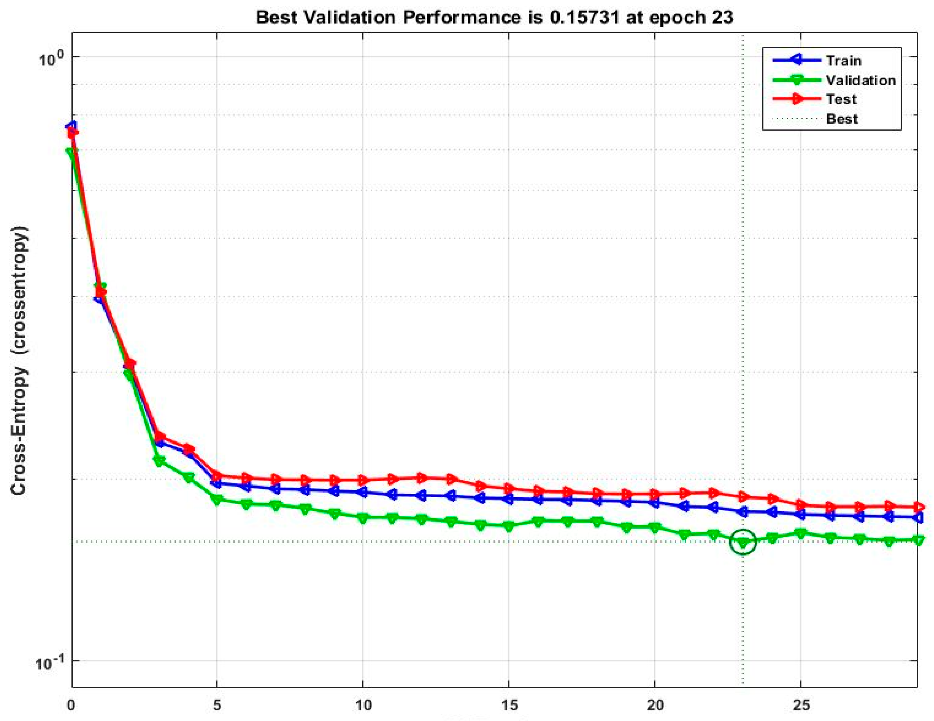
Figure 18 shows the best validation performance of the network. The plot is used to obtain a plot of training record error values against the number of training epochs, eventually, the error of training decreases after more epochs and retraining, and the best performance is taken from the epoch (epoch 23) with the lowest validation error.
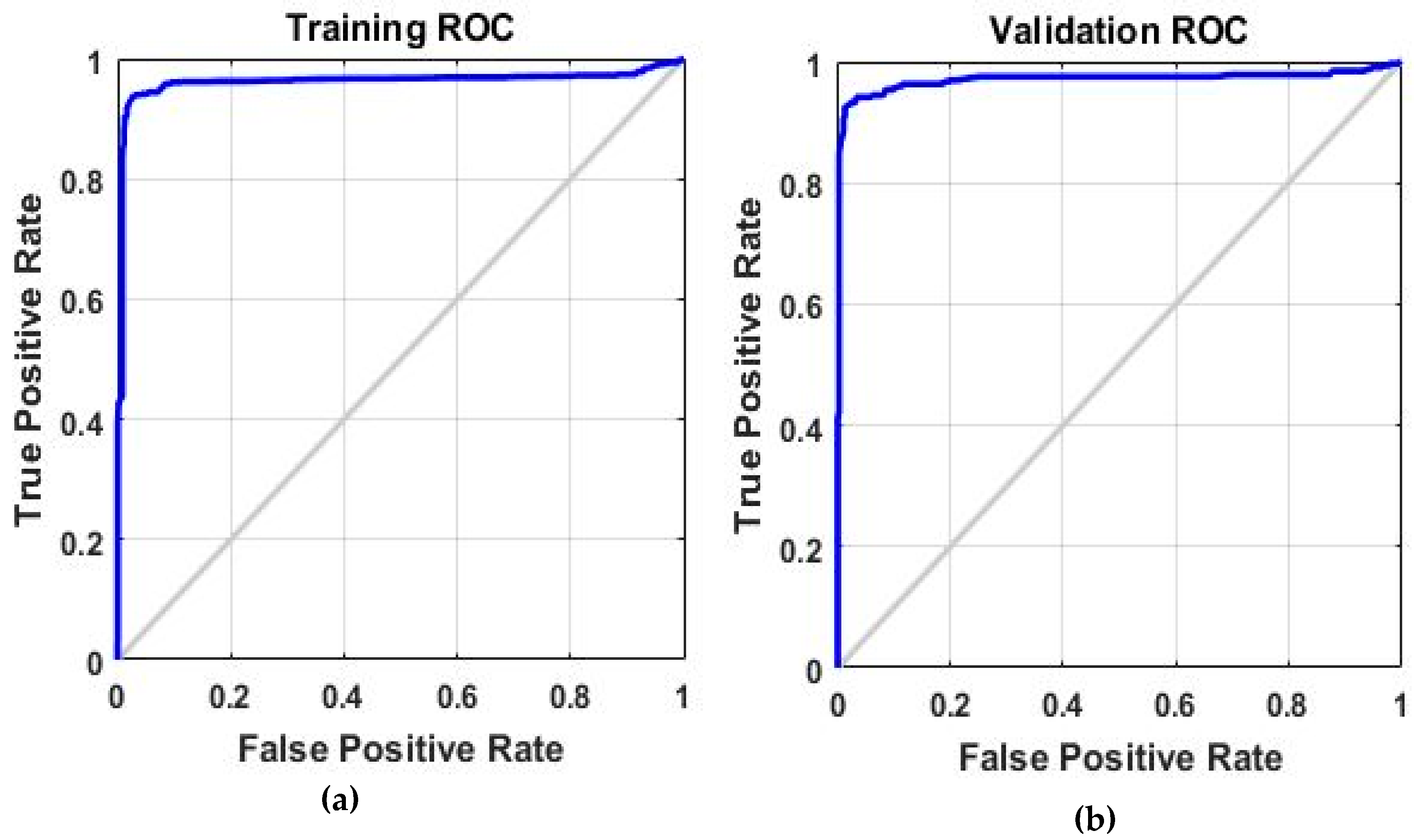
Figure 19 shows the test performance of the network (input—hidden networks—output), and contains all of the information related to the training of the network. The structure keeps track of several variables during the course of training, such as the value of the performance function, and the magnitude of the gradient. The best validation indicates the iteration at which performance reached a minimum.
7. Conclusions
This paper examines the IEC 61850-9-2 standard based on the sampled measured values. The paper provides different methods to compare the timing analysis between the merging unit of physical protection relay (IED) that converts the current and voltage signals from the conventional transformers into a digital signal and shares it with sampling frequency (4000 samples/second) and the simulated merging unit of an Omicron 256 CMC that is used to publish SMV to the physical relay (IED-subscriber). The implementation and configuration of the test requires two IEDs are applicable to sending and receiving SMV and GOOSE messages according to standard IEC 61850. Modern IEDs are able to publish four current signals and four voltage signals and share the voltage in the power system. GPS is used to synchronize the time and keep all the devices in the same time and without phase offset. In summary, we can conclude the following from the experiments above:
- The IED-subscriber starts to send sampled measured values once the global clock is applied (GPS - time synchronization), conversely, IED-subscriber does not send or publish SMV once the internal clock is applied from the publisher IED.
- The interval time between the samples is 250 µs according to the IEC 61850 standard, and the network analysis tool shows that four MAC addresses are available, in this case (CMC-publisher, IED-publisher- 2x IED-Subscriber) with time synchronization is applied, however, the interval time is around 240 µs with the local clock of the publisher IED or CMC merging unit, and the interval time is around 230 µs with the global clock (GPS) applied.
- The number of samples per millisecond of IED-publisher: the number of packets is not constant, the range was between 3 to 5 packets/ms, while with CMC-publisher: the number of packets is almost constant at 5 packets/ms.
- GOOSE message configuration is implemented to the IEDs (sender-receiver), the GOOSE message is sent to the receiver IED (tripping signal), the signal is duplicated four times with a size of 147 bytes per packet, the average interval time between the packets was practically constant from the first to the fourth packets (278 µs) and the average interval between the fourth and the fifth packet was 102 milliseconds.
- IED-subscriber is subscribing the SMV from the IED-publisher and CMC-publisher equally, IED-subscriber is unable to recognize who is the publisher of the SMV (IED or CMC) due to the fact the CMC-publisher has the same dataset as the IED-publisher (that is, in fact, what happened when CMC-publisher was simulating the IED-publisher). Wherefore, a model is applied to predict if the IED-subscriber would recognize which merging unit is sending the sampled values based on different attributes, to implement the approach, train a classifier using different models and measure the accuracy and compare models, using the classifier for prediction. The preparation data includes two parameters (number of samples/ms - interval time between the packets) for each publisher of SMV (IED or CMC). By using neural net pattern recognition that solves the pattern recognition problem using two layer feed networks (nprtool), the inputs and the target provided to the network and the algorithm break up the data into test sets (training 70%- validation 15%- testing 15%), and the best validation was in the 23rd epoch.
- This method can be used for optimization of testing procedures in substations where IEC 61850-9-2LE are implemented. This method can be used for shorter test preparation, to lower the cost and the method can lower the cost and help support research projects since it allows one to implement better platform and services as well as to integrate different communication protocols when necessary.
Author Contributions
Conceptualization, K.W.; Data curation, K.W. and V.J.; Formal analysis, K.W.; Investigation, K.W.; Methodology, P.T., K.W. and V.W.; Project administration, P.T.; Resources, P.T.; Supervision, P.T.; Visualization, K.W.; Writing—original draft, K.W.
Funding
This research was funded by the Ministry of Education, Youth and Sports of the Czech Republic under OP VVV Programme (project No. CZ.02.1.01/0.0/0.0/16_013/0001638 CVVOZE Power Laboratories—Modernization of Research Infrastructure).
Acknowledgments
This research work has been carried out in the Centre for Research and Utilization of Renewable Energy (CVVOZE). Authors gratefully acknowledge financial support from the Ministry of Education, Youth and Sports of the Czech Republic under OP VVV Programme (project No. CZ.02.1.01/0.0/0.0/16_013/0001638 CVVOZE Power Laboratories - Modernization of Research Infrastructure).
Conflicts of Interest
The authors declare no conflict of interest.
References
- Sidhu, T.S.; Pradeep, K. Gangadharan. Control and automation of power system substation using IEC61850 communication. In Proceedings of the 2005 IEEE Conference on Control Applications (IEEE CCA 2005), Toronto, ON, Canada, 28–31 August 2005. [Google Scholar]
- Kriger, C.; Shaheen, B.; John-Charly, R.-M. A detailed analysis of the GOOSE message structure in an IEC 61850 standard-based substation automation system. Int. J. Comput. Commun. Control 2013, 8, 708–721. [Google Scholar] [CrossRef]
- Štefanka, M. Application of sensors and digitalization based on IEC 61850 in medium voltage networks and switchgears. Ph.D. Thesis, Brno University of Technology, Faculty of Electrical Engineering and Communication, Brno, Czech Republic, 2016. [Google Scholar]
- Andersson, L.; Brand, K.P.; Brunner, C.; Wimmer, W. Reliability investigations for SA communication architectures based on IEC 61850. In Proceedings of the IEEE Power Tech, St. Petersburg, Russia, 27–30 June 2005. [Google Scholar]
- Sheng, C.H.E.N. Application of system networking for substation automation. Power Syst. Technol. Beijing 2003, 27, 72–75. [Google Scholar]
- Popova, S.; Iliev, S.; Trifonov, M. Neural Network Prediction of the Electricity Consumption of Trolleybus and Tram Transport in Sofia City. In Proceedings of the Latest Trends in Energy, Environment and Development, Proc. of the Int. Conf. on Urban Planning and Transportation (UPT’14), Salerno, Italy, 3–5 June 2014; pp. 116–120. [Google Scholar]
- Dolezilek, D. IEC 61850: What you need to know about functionality and practical implementation. In Proceedings of the 2006 IEEE Power Systems Conference: Advanced Metering, Protection, Control, Communication, and Distributed Resources (PS’06), Clemson, SC, USA, 14–17 March 2006; pp. 1–17. [Google Scholar]
- Ingram, D.M.E.; Schaub, P.; Richard, R.T.; Duncan, A.C. Performance analysis of IEC 61850 sampled value process bus networks. IEEE Trans. Ind. Inform. 2003, 9, 1445–1454. [Google Scholar] [CrossRef]
- Jiang, W.; Henning, S. Modeling of packet loss and delay and their effect on real-time multimedia service quality. In Proceedings of the Nossdav’2000, Chapel Hill, NC, USA, 26–28 June 2000. [Google Scholar]
- Xiang, G.; Pei-Chao, Z. Main features and key technologies of digital substation. Power Syst. Technol. 2006, 23. Available online: http://en.cnki.com.cn/Article_en/CJFDTOTAL-DWJS200623015.htm (accessed on 27 April 2019).
- Mekkanen, M. On reliability and performance analyses of iec 61850 for digital sas. Ph.D. Thesis, University of Vaasa Faculty of Technology Department of Computer Science, Vaasa, Finland, 2015. [Google Scholar]
- Goran, J.; Havelka, J.; Capuder, T.; Sučić, S. Laboratory Test Bed for Analyzing Fault-Detection Reaction Times of Protection Relays in Different Substation Topologies. Energies 2018, 11, 2482. [Google Scholar]
- Silos, A.; Señís, A.; De Pozuelo, R.M.; Zaballos, A. Using IEC 61850 GOOSE Service for Adaptive ANSI 67/67N Protection in Ring Main Systems with Distributed Energy Resources. Energies 2017, 10, 1685. [Google Scholar] [CrossRef]
- Cai, Y.; Chen, Y.; Li, Y.; Cao, Y.; Zeng, X. Reliability Analysis of Cyber–Physical Systems: Case of the Substation Based on the IEC 61850 Standard in China. Energies 2018, 11, 2589. [Google Scholar] [CrossRef]
- O’Reilly, R.; Beng, T.C.; Dogger, G. Hidden challenges in the implementation of 61850 in larger substation automation projects. 2016. Available online: https://pdfs.semanticscholar.org/02c7/2e128c2937b31474c40cb5a5bde50f06ecc5.pdf (accessed on 27 April 2019).
- Wannous, K.; Toman, P. Sharing sampled values between two protection relays according to standard IEC 61850-9-2LE. In Proceedings of the 19th IEEE International Scientific Conference on Electric Power Engineering (EPE), Brno, Czech Republic, 16–18 May 2018. [Google Scholar]
- Mlynek, P.; Misurec, J.; Toman, P.; Silhavy, P.; Fujdiak, R.; Slacik, J.; Samouylov, K. Performance Testing and Methodology for Evaluation of Power Line Communication. Elektron. Elektrotechnika 2018, 24, 88–96. [Google Scholar] [CrossRef]
- Patel, N. IEC 61850: Horizontal Goose Communication and Overview: IEC 61850 Horizontal Communication, Goose Messaging and Documentation: IEC 61850 Standard Overview and Understanding; Lambert Academic Publishing: Saarbrücken, Germany, 2011. [Google Scholar]
- Stefanka, M.; Prokop, V.; Salge, G. Application of IEC 61850-9-2 in MV Switchgear with Sensors Use; IET: London, UK, 2013. [Google Scholar]
- Raussi, P. Real-Time Laboratory Interconnection for Smart Grid Testing; LUT University: Petra, Jordan, 2017. [Google Scholar]
Figure 1.
IEC 61850 structure.

Figure 2.
IEC 61850 Object Name Structure.

Figure 3.
The full scheme of testing the IEC 61850 (SMV-GOOSE).

Figure 4.
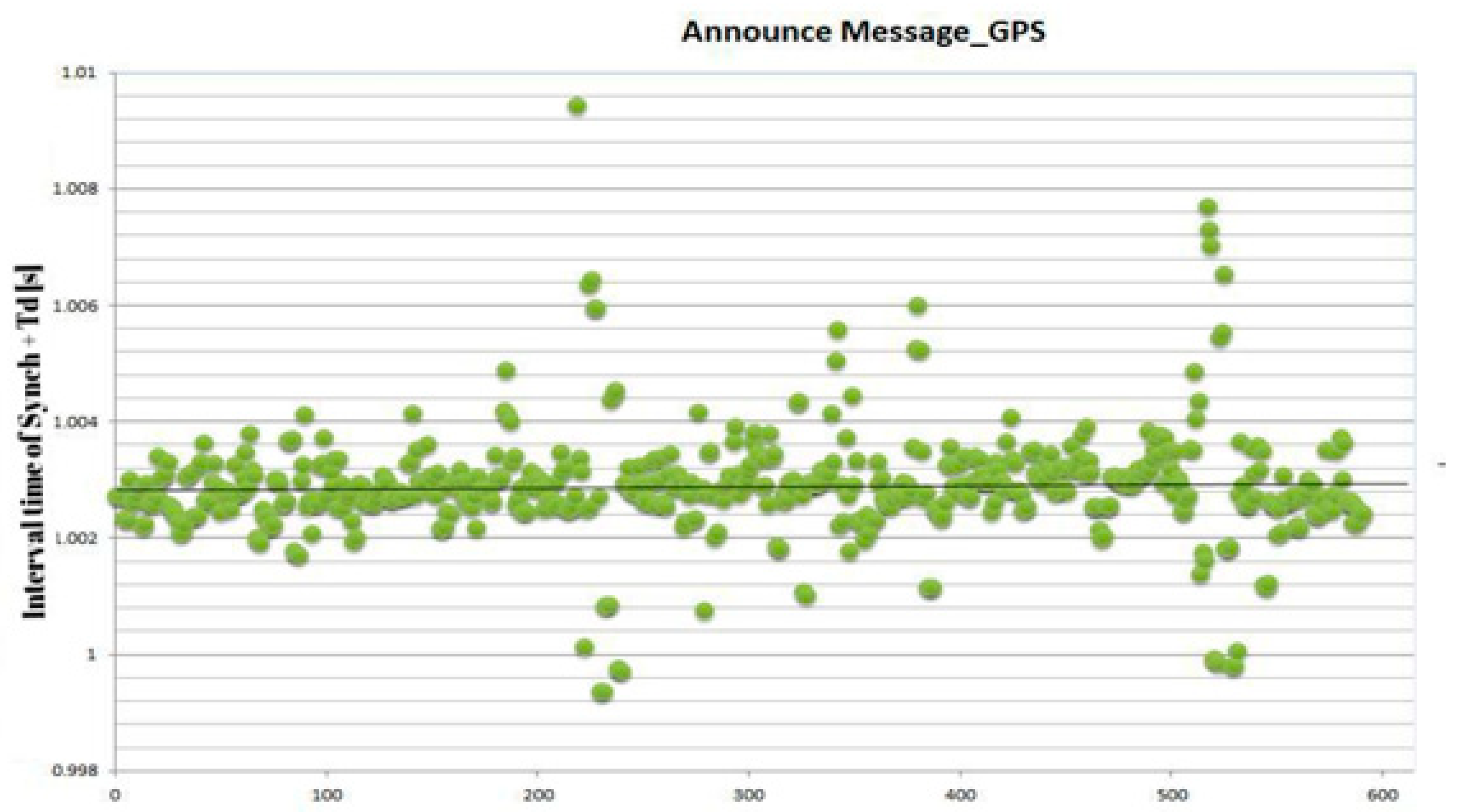
The measured interval time between synchronization announcement messages.

Figure 5.
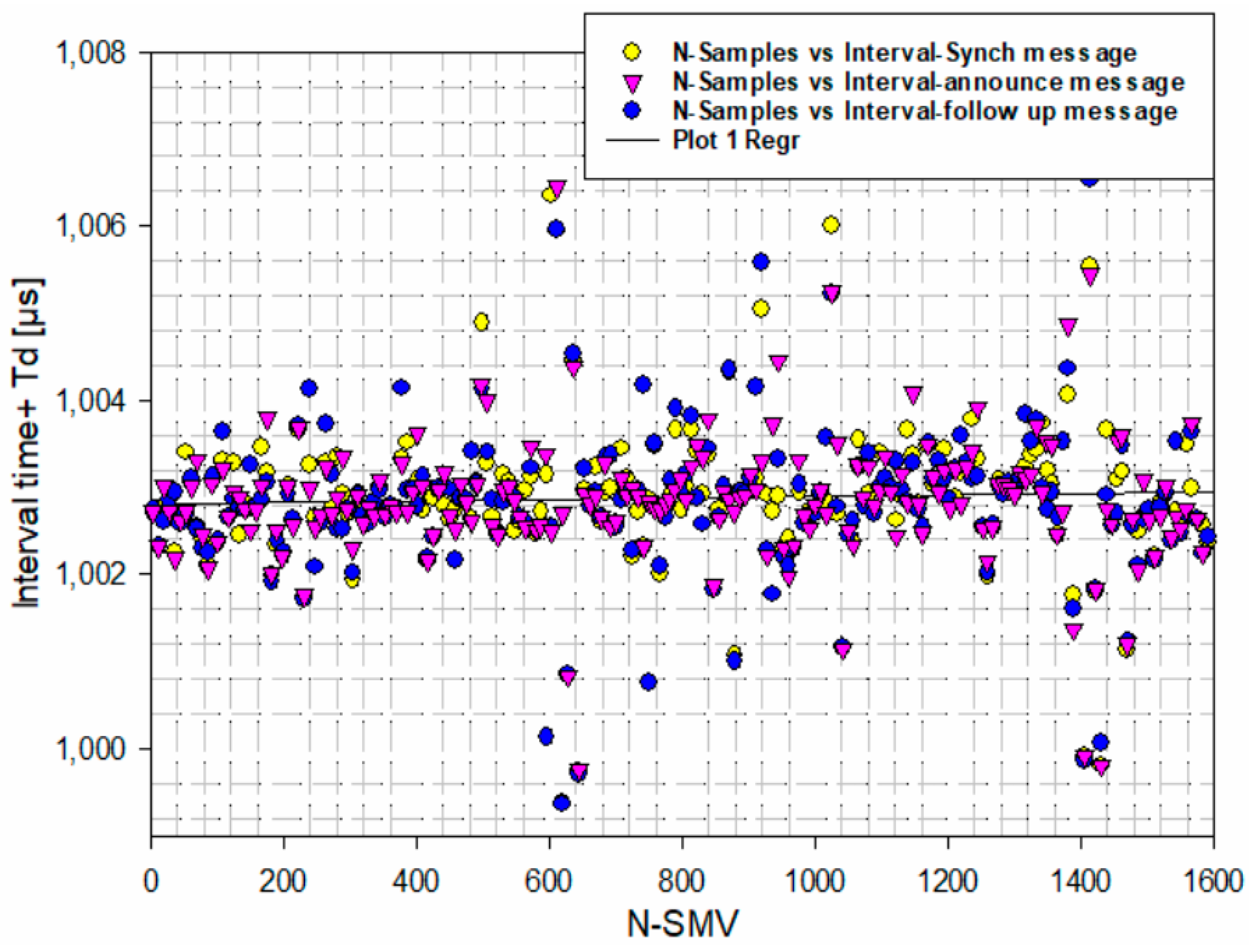
The measured interval time between announcement messages—follow up messages—synch messages of synchronization.
Figure 5.
The measured interval time between announcement messages—follow up messages—synch messages of synchronization.

Figure 6.
Wiring of CMLIB A.

Figure 7.
Experiment structure and network devices.

Figure 8.
Omicron sampled measured values test configuration.

Figure 9.
The interval time in microseconds between packets of CMC—Simulator, an IED.

Figure 10.
The calculation of time duration to publish the sampled values. The CMC publisher sends packets with interval 250 µs and IED-72 follows by sending packets to keep the system synchronized.
Figure 10.
The calculation of time duration to publish the sampled values. The CMC publisher sends packets with interval 250 µs and IED-72 follows by sending packets to keep the system synchronized.

Figure 11.
The interval time + delay time in µsec between publisher/subscriber IEDs.

Figure 12.
The interval time + delay time in µsec between publisher/subscriber (CMC & IED-72).

Figure 13.
Number of packets per ms for IED publisher/CMC MU.

Figure 14.
The full scheme of testing the IEC 61850 (SMV-GOOSE). (a) Shows the mapping of a GOOSE message with the dataset details. It shows the tripping signal is false before increasing the current and overcurrent function of IED takes action, (b) shows changing of the status to true, which means the GOOSE message (tripping signal) is sent to the subscriber.

Figure 15.
The structure of IED SCL and GOOSE mapping.

Figure 16.
GOOSE Messages duplicities for five different GOOSE messages. n-repetition.

Figure 17.
Data preparation of parameters.

Figure 18.
The best validation performance at epoch 23, validation error at the lowest point.

Figure 19.
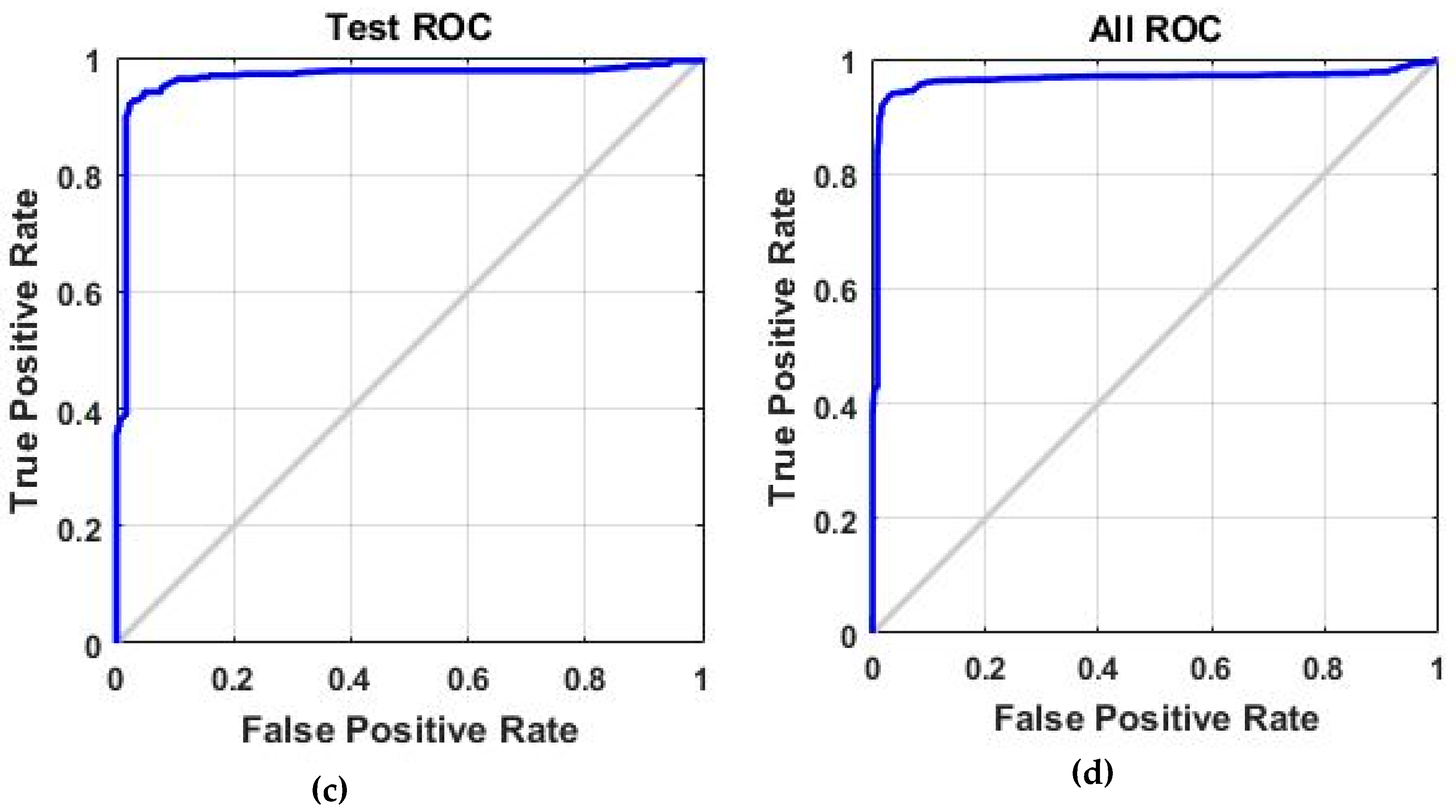
The receiver operation characteristic curve (a) shows the training ROC that is exploring the tradeoff between true positives and false positives, this curve is a metric used to examine the quality classifier, (b) represents the validation ROC, (c) represents the test ROC, (d) represents the All ROC.
Figure 19.
The receiver operation characteristic curve (a) shows the training ROC that is exploring the tradeoff between true positives and false positives, this curve is a metric used to examine the quality classifier, (b) represents the validation ROC, (c) represents the test ROC, (d) represents the All ROC.


Table 1.
GPS data sheet and timing protocols.
| Timing Accuracy | Supported Timing Protocols | Specifications | Channels and Frequency |
|---|---|---|---|
| ±100 ns to reference time (TAI/UTC) | PTP | CMGPS 588 synchronization unit with integrated antenna and timing receiver | 12 channel GPS receiver, Frequency: 1575.42 MHz |
Table 2.
PTP time synchronization and settings.
| CMCGPS 588 | Time Interval | ||
|---|---|---|---|
| Status | |||
| GPS | Locked | Sync interval | 1 s |
| PTP | Master | Announce interval | 1 s |
| NTP | Synchronized | Announce receipt timeout | 3 s |
| Satellites usable | 4 | Peer mean path delay | 85 ns |
Table 3.
CMLIB A Hardware Configuration
| Linear Voltage Sensor | Rogowski Current Sensor | ||
|---|---|---|---|
| Nominal voltage of OMICRON | 2 V | Nominal voltage of OMICRON | 150 mV |
| Output System channels | Line to Line out 1–3 | Output System channels | Line to Line out 4–6 |
| Min. Frequency | 0 Hz | Min. Frequency | 0 Hz |
| Max. Frequency | 1 kHz | Max. Frequency | 395 Hz |
Table 4.
Time display and time references.
| Frame Size [bytes] | Round Trip Latency [µs] |
|---|---|
| 128 | 241 |
| 256 | 292 |
| 512 | 426 |
| 1280 | 645 |
Table 5.
PTP time synchronization and settings.
| IEC 61850 -9-2 | 50 Hz System | 60 Hz System | SMV_Publisher1 | SMV_Publisher2 |
|---|---|---|---|---|
| HSR redundant network | 4 | 4 | 12.3Mb/s | 37.7 Mb/s |
| PRP redundant network | 9 | 8 | 12.3 Mb/s | 87.7 Mb/s |
| T | 250 µs | 208 µs | 5.12 Mb/s, 50 Hz | 6.16 Mb/s, 60 Hz |
Table 6.
Data preparation and input array size.
| Input | Target/Output | ||
|---|---|---|---|
| Parameter | IED-Publisher | CMC_ Simulated | IED-Subscriber |
| Interval time | (4000 × 1) | (4000 × 1) | IED |
| Number of samples per ms | (4000 × 1) | (4000 × 1) | CMC |
Table 7.
Training set and test set.
| Training Set | Test Set | ||||
|---|---|---|---|---|---|
| Value | Count | Precent | Value | Count | Precent |
| CMC | 2379 | 49.55% | CMC | 1621 | 50.66% |
| IED | 2422 | 50.45% | IED | 1579 | 49.34% |
© 2019 by the authors. Licensee MDPI, Basel, Switzerland. This article is an open access article distributed under the terms and conditions of the Creative Commons Attribution (CC BY) license (http://creativecommons.org/licenses/by/4.0/).
Share and Cite
MDPI and ACS Style
Wannous, K.; Toman, P.; Jurák, V.; Wasserbauer, V. Analysis of IEC 61850-9-2LE Measured Values Using a Neural Network. Energies 2019, 12, 1618. https://0-doi-org.brum.beds.ac.uk/10.3390/en12091618
AMA Style
Wannous K, Toman P, Jurák V, Wasserbauer V. Analysis of IEC 61850-9-2LE Measured Values Using a Neural Network. Energies. 2019; 12(9):1618. https://0-doi-org.brum.beds.ac.uk/10.3390/en12091618
Chicago/Turabian StyleWannous, Kinan, Petr Toman, Viktor Jurák, and Vojtěch Wasserbauer. 2019. "Analysis of IEC 61850-9-2LE Measured Values Using a Neural Network" Energies 12, no. 9: 1618. https://0-doi-org.brum.beds.ac.uk/10.3390/en12091618
Note that from the first issue of 2016, this journal uses article numbers instead of page numbers. See further details here.