The Application of Building Physics in the Design of Roof Windows


Department of Architecture and Environment, University Center of Energy Efficient Buildings, Czech Technical University in Prague, Třinecká 1024, 273 43 Buštěhrad, Czech Republic
*
Author to whom correspondence should be addressed.
Energies 2019, 12(12), 2300; https://0-doi-org.brum.beds.ac.uk/10.3390/en12122300
Submission received: 22 April 2019
/
Revised: 9 June 2019
/
Accepted: 12 June 2019
/
Published: 16 June 2019
(This article belongs to the Special Issue Building Thermal Envelope)
Abstract
:This paper deals with a small but important component in a building envelope, namely roof windows in pitched roofs. Building physics methods were used to support the search for new solutions which correspond to the maximum extent for requirements for passive house level design. The first part of the paper summarizes the key phenomena of heat transfer, mainly based on a comparison of vertical windows in walls. The results of repeated two-dimensional heat transfer calculations in the form of parametric studies are presented in order to express the most important factors influencing thermal transmittance and minimum surface temperatures. Several configuration variants suitable for technical design are discussed. It was found that a combination of wood and hardened plastics in the window frame and sash is the preferred solution. The resulting thermal transmittance can be up to twice as low as usual (from 0.7 down to 0.5 W/(m2·K), with further development ongoing. Surface temperature requirements to avoid the risk of condensation can be safely fulfilled. Concurrently, it is shown that the relative influence of thermal coupling between the window and roof construction increases with the improvement of window quality. Specific attention was given to the effect of the slanting of the side lining, which was analyzed by simulation and measurement in a daylight laboratory. The increase in thermal coupling due to slanting was found to be negligible. Motivations for specific building physics research are mentioned, such as the need to study the surface heat transfer in the case of inclined windows placed in a deep lining.
1. Introduction
Building physics, e.g., [1], including heat and moisture transfer, building-energy performance, energy assessments of elements and buildings, building acoustics, daylighting, the distribution of contaminants, etc., can be perceived as a set of rules for the assessment of constructions and buildings [2]. It can also be perceived as a set of sub-tools that is used actively during preparation and development work. Individual requirements need to be seen as interconnected, such as the requirement for daylight versus the requirement to limit the risk of a room overheating. Such a process accompanying development work should be perceived as multilevel. When applying building physics knowledge and practical tools, it is necessary to choose the key phenomena that will be prioritized.
The paper discusses the use of building physics methods to develop a roof window suitable for passive buildings. This was the subject of a joint project between a research organization and an innovative company specializing in the production of windows [3]. The contribution of this paper is to highlight selected phenomena and show possible applications of the technical solution of the new component. At the same time, it should be remembered that, in addition to the obvious technically oriented approaches, the user’s customs (window opening, cleaning) and aesthetic requirements must be considered in the design of the final product.
Passive buildings [4] have become a clearly defined category of energy-efficient buildings [5], which is in line with the trend of sustainable solutions [6] over more than 25 years of development. Design methods and voluntary certification procedures are steady, and in some countries and regions they may be linked to subsidy policies or building regulations. At the same time, building solutions together with technical systems (minimizing heat penetration through the building envelope, minimizing heat losses by ventilation with heat recovery from the ventilating air) are the basis for the downstream categories of energy-optimized buildings obtaining a significant share of their energy from renewable sources (passive house premium [7], nearly zero-energy buildings (NZEBs) [8], Effizienzhaus Plus [9], etc.). Even a seemingly small element, such as a window, can be significant in terms of the reduction of energy use, and can thus be part of the solution.
In order to meet the requirements for energy-optimized buildings in cold to moderate climates, it is generally necessary to use windows with a thermal transmittance of around 0.8 W/(m2·K) [10]. However, roof windows of this quality are not yet normally available. At the same time, the effect of installation into the roof construction should be taken into account, since there is a considerably larger additional thermal flow than for windows in perimeter walls.
For roof windows, the condensation of water vapor on their inner surfaces, especially at the edges of the glass, can be observed at low external air temperatures. Together with an effort to reduce the heat transfer of the windows, the spacing frames of the glazing units, the shape of the window frames, and the materials used in their construction have also been gradually improved.
It is known that window frames typically have a higher thermal transmittance than modern glazing units [11]. This is a particularly significant phenomenon due to the smaller dimensions of the roof windows (in the case of openable windows, the window frame means an assembly of parts, the fixed frame, and the movable frame of the sash).
One of the possible ways to reduce heat leakage at the edge of a window is to fit additional thermal insulation elements during the installation of the window from the outside of the frames [12].
Roof windows are the weakest elements of the building envelope in terms of heat losses. For this reason, they are not popular with designers involved with passive buildings. However, they must be used in some cases, and the consequence of increased heat transmission must be compensated for in order to achieve the passive house criteria. This critical situation can be illustrated by the fact that, in the database of components certified for passive houses [13], of 268 positions for windows (frames and connections), only two deal with roof windows (in one case equipped with quadruple glazing, in the other case equipped with triple and double glazing combined in one assembly).
The aim of the project in [3] was to find a solution for a roof window so that the thermal transmittance of the entire window corresponds to the requirements for passive buildings and so that the temperature on the frame surface meets the requirement to eliminate the risk of surface water condensation under reference conditions in the interior. The possible increased risk of the overheating of rooms during the summer due to solar gain was not explicitly addressed in this project.
This paper discusses methods used during research and development studies in Section 3. It then introduces and comments on the main findings in Section 4. Appendix A shows, through a simple case study, the effects of roof windows of different quality on the overall thermal transmittance of the building envelope of a typical family house. Preliminary studies about heat transfer phenomena close to window surfaces are introduced in Appendix B.
2. Problem Analysis
To analyze the problem, a comparison of a roof window with a vertical window in a perimeter wall was performed (see Figure 1 and Figure 2).
Heat transfer in the air cavities between glazing panes is generally larger due to increased heat convection caused by air movement (the more inclined the more significant; nonlinear). As a result, thermal transmittance is increased in the range of 0.1 to 0.2 W/(m2·K) relative to the whole window if calculated according to [14].
Considering the fact that frames are weaker parts of a window in terms of the total thermal transmittance, attention is given to a more detailed description of the thermal properties of the frames [15], and to their improvement. Such an approach cannot be clearly conducted by the study of roof windows.
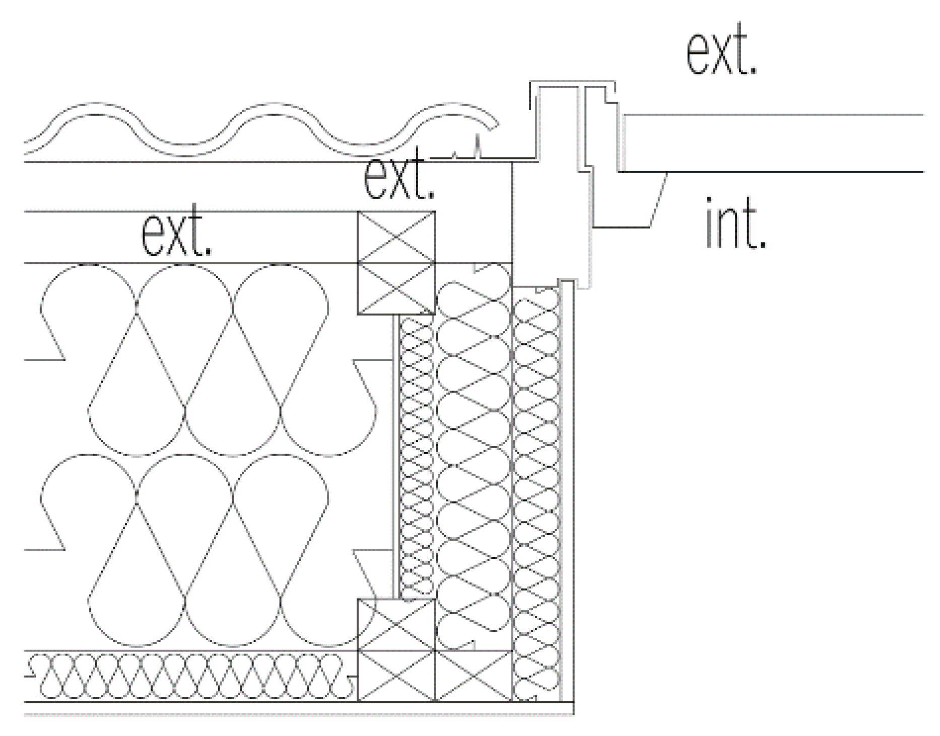
Heat is transferred due to a connection of the window to the opaque part of the building envelope: In the design of vertical windows, it is attempted to minimize such thermal coupling by searching for the optimal position of a window in the wall [16] and the optimal geometry and materials for the construction detail. On the contrary, in roof windows, a very significant problem arises due to the windows’ geometrical situation (Figure 2). The external perimeter of the window is situated in the cold area of the roof. Therefore, it is not possible to achieve the so-called thermal-bridge free solution (see Figure 3). The result is expressed as linear thermal transmittance [17], ψw (W/(m·K)). Although the values recommended in the Czech national standard [18] are larger than those for vertical windows in perimeter walls, they may not be easily reached (Table 1).
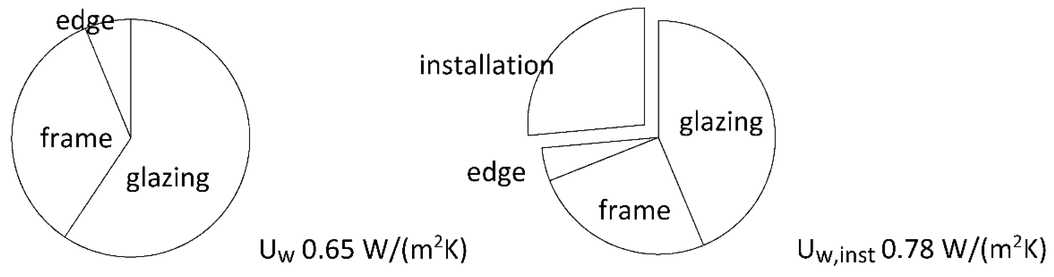
Simple calculations performed in [19] (Figure 3) have shown that unavoidable heat transfer due to the thermal coupling between the window and the roof plays an important role. For this reason, it is recommended to integrate the additional heat transfer due to thermal coupling in the (extended) thermal transmittance, Uw,inst, in order to obtain a “full picture” in one value [10]:
where describes the influence of the installation, Ug is the thermal transmittance of the glazing unit (W/(m2·K)), Uf is the thermal transmittance of the frame (W/(m2·K)), the thermal bridges of the glazing edge are expressed by the linear thermal transmittance, (W/(m·K)), and the thermal bridges due to the installation in the roof are expressed by the linear thermal transmittance of the window, (W/(m·K)). Figure 3 shows the results of a preliminary calculation for a hypothetical window of excellent quality: Ug 0.60 W/(m2·K), Uf 0.60 W/(m2·K), 0.03 W/(m·K), 0.05 W/(m·K), reference window size. It can be seen that, for improvements to roof windows, all parts are of high importance, i.e., the glazing, frame, installation method, and overall geometry.
As a rule, heat transfer is calculated and measured vertically according to standardized test procedures [20], even for later use in an inclined position. Thus, if the goal is to achieve identical heat transfer to that in vertical windows, the requirement should be more stringent, being reduced at least by 0.1 W/(m2·K). The standard [18] is partly based on this approach, as shown in Table 2, for the required and recommended values of thermal transmittance. During preparation of the standard [18] this approach was not used for passive house recommendations because of the fact that windows of corresponding low thermal transmittance were not available.
Another important fact is that roof windows are usually smaller than windows in walls, and therefore the proportion of the frame, as the weaker element in terms of heat transfer, will be significant. The reference size of the roof window [21] is 1.14 m × 1.40 m, and the conversion to different window dimensions is only performed in practice in exceptional cases.
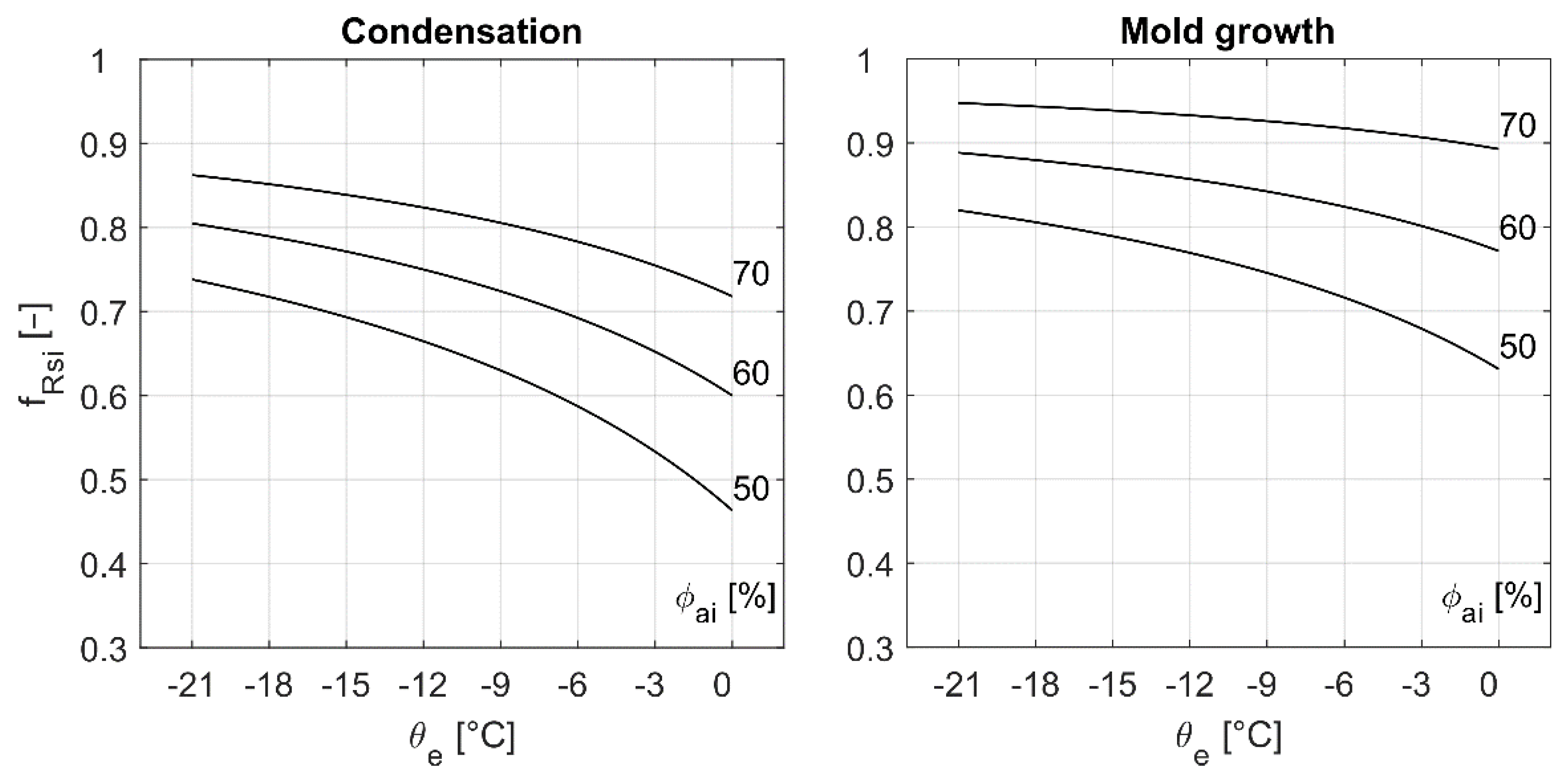
Excessively low interior surface temperatures can create conditions for the surface condensation of water vapor and mold growth (expected above a critical air humidity of 80%). This applies in particular to window frames and glazing edges. The surface temperature factor, fRsi = (θi − θe)/(θai − θe), is used for the assessment. Its required minimum values [18] are shown in Figure 4, and depend on the outdoor air temperature, indoor air temperature, and relative humidity.
The surface heat transfer coefficient, hsi (W/(m2·K)), describing the heat transfer between the internal surface of the window and surroundings can be different for inclined roof windows and for vertical windows. Smaller inclined roof windows are additionally often influenced by heating bodies close by, and the situation can therefore be very different.
Requirements on the thermal transmittance of the roof construction result in an overall thickness of approximately 400 mm or more. This can negatively influence the daylight quality due to the very deep side lining. Therefore, the distribution of daylight in rooms as a primary function of each window should also be studied very carefully.
Additionally, in the case of roof windows, the situation of radiative heat exchange between the glazing and the two perpendicular side linings is fundamentally different from that of a wall window. Heat transfer can also be significantly affected by the presence of a heating body below the window (differently depending on the power, temperature, proportion of the radiant and convective heat-to-room transfer, and overall space situation). Moreover, a deep lining contributes to a different air flow in the room and in the space in front of the window.
The radiative heat exchange between the external window surface and the (clear) sky [1] is higher for roof windows (e.g., multiplied by a factor of 1.5 for 45° sloped windows). This leads to an increase in the total external surface heat transfer coefficient, hse (W/(m2·K)).
In summer, specific phenomena should be considered (although they are not the subject of this paper). These include passive solar gains in the rooms and the resulting risk of room overheating, which are primarily influenced by the orientation of the façade/roof, window size, and the coefficient of the permeability of total solar radiation (solar factor), g (-), of the glazing unit, by the shading from external obstacles and shading devices. The overall effect depends on several other parameters of the (occupied) room, including the thermal inertia, ventilation strategy, and actual climatic data. The external air can be significantly warmer close to the roof surface (heated by the roof covering).
Generally, a higher passive solar gain can be expected due to the inclination of roof windows. Moreover, efficient external shading, such as venetian blinds, are not applicable to roof windows.
3. Methods
3.1. Parametric Studies
Introductory parametric studies [3] involving 2D-heat transfer calculations using the COMSOL Multiphysics [22] modeling software were carried out to map the key dependencies of the overall layout and geometry of window and frame material on the window’s thermal performance. Initially, two different configurations were studied: (i) Usual assembly with high-performance glazing near the exterior (configuration A); and (ii) alternative assembly with a window casing equipped with high-performance glazing near the interior and an additional single-glazed pane at the exterior side (configuration B) (Figure 5).
The calculation model followed the rules given in [23]. Connection to the roof is considered here as adiabatic; this means that the effects of thermal couplings were not included. For that reason, the estimation of the minimum interior surface temperature is only indicative.
A glazing unit consisting of more panes and cavities filled by Argon was simplified for the calculation as a homogeneous solid material having equivalent thermal conductivity back-calculated from the known thermal transmittance of the glazing unit, Ug. The connection between the frame and the glazing unit was simplified by using a two-box-method [24] for spacers of known characteristics. Air gaps between the fixed and movable part of the frame were simulated according to [23].
In this case, high-performance homogeneous materials for the frame were considered. The thermal conductivities of the fixed and movable part were 0.039 W/(m·K) and 0.065 W/(m·K), respectively. This corresponds to the use of hardened polystyrene [25] with a density of 100 and 400 kg/m3, respectively. The thermal transmittance of the glazing unit was 0.6 W/(m2·K) for triple glazing and 1.0 W/(m2·K) for double glazing. Calculations were performed for indoor and outdoor air temperatures of 20 and 0 °C, respectively.
During the parametric studies, several geometrical parameters and material parameters were changed over a relatively wide range in order to determine their importance within the whole configuration. The thermal transmittance of the glazing was fixed.
3.2. Real Design Solution
Repeated 2D-heat transfer calculations in steady state conditions were performed for selected configurations according to consultations with the development team. The HT-Flux software [26] was used to analyze representative cross-sections (for head and sill, over and under the hinge). The thermal transmittance of the frame, the linear thermal transmittance due to the connection between the glazing and frame, and the resulting thermal transmittance for the reference window size (1.14 m × 1.40 m) were estimated for each variant. Additionally, a preliminary estimate was made of the minimum surface temperature. The simplifications for modeling were identical to those described in Section 3.1. Material parameters and boundary conditions are summarized in Section 4.2.
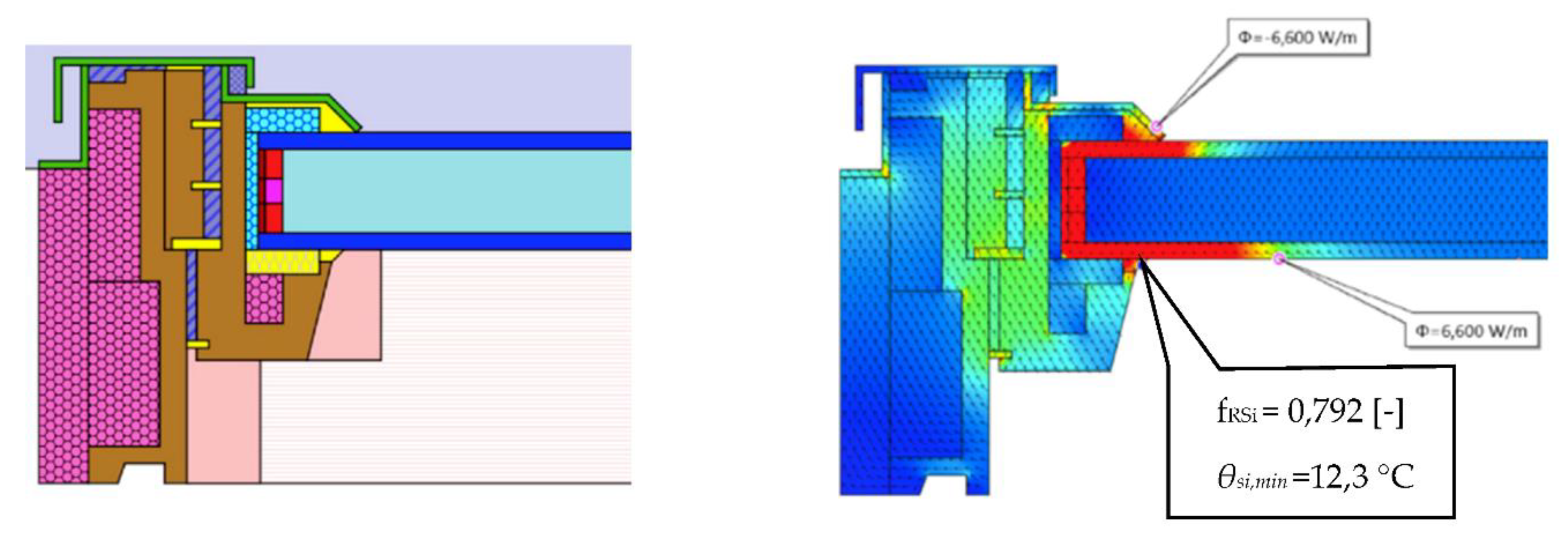
The effects of thermal coupling between the window and the roof construction were analyzed for selected window variants. Again, the HT-Flux software was used to analyze representative cross-sections (e.g., Figure 2) for a typical configuration of a pitched roof for passive house quality.
The thermal transmittance of the installed window, Uw,inst, was estimated for the reference window size. Moreover, the minimum window surface temperature and corresponding factors, fRsi, were evaluated [27].
3.3. Daylight Simulation
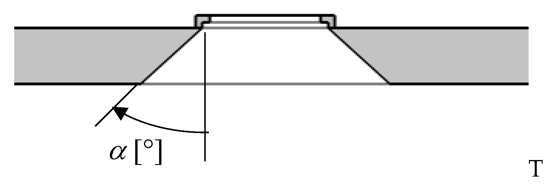
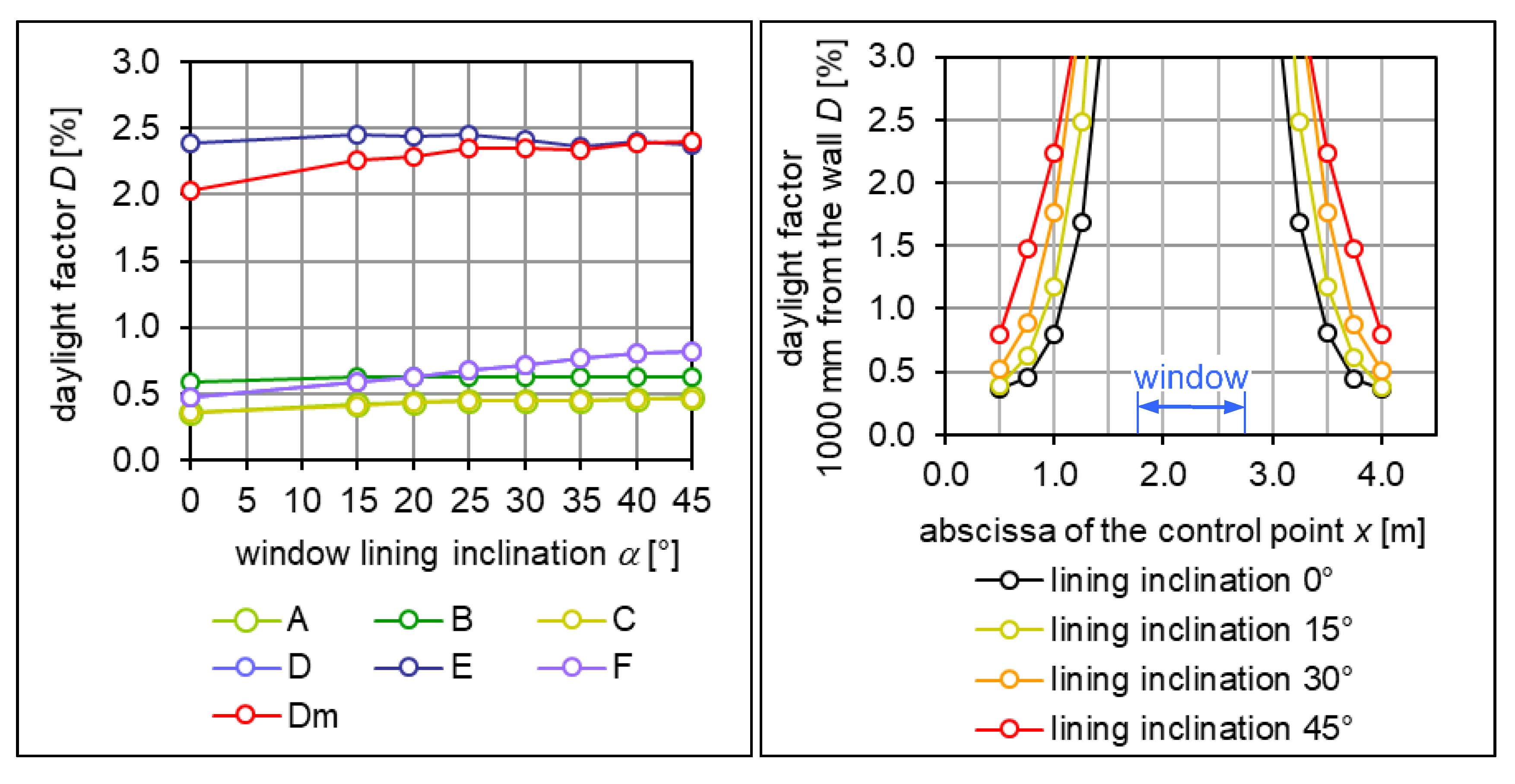
In this study, the problem of daylighting was preliminarily investigated by means of numerical simulations. The influence of the possible slanting of the roof window lining was investigated. The quantity of daylight and its spatial distribution may change with the degree of lining slanting (that is, the angle, α, between the lining plane and the plane perpendicular to the roof, see Figure 6). In order to quantify this effect, the daylight factor, D (%), was calculated by means of a validated software tool [28] using the CIE standard overcast sky model at a horizontal reference plane in an attic room lit by a roof window. It was calculated repeatedly with the angle, α, varying stepwise from 15 to 45°.
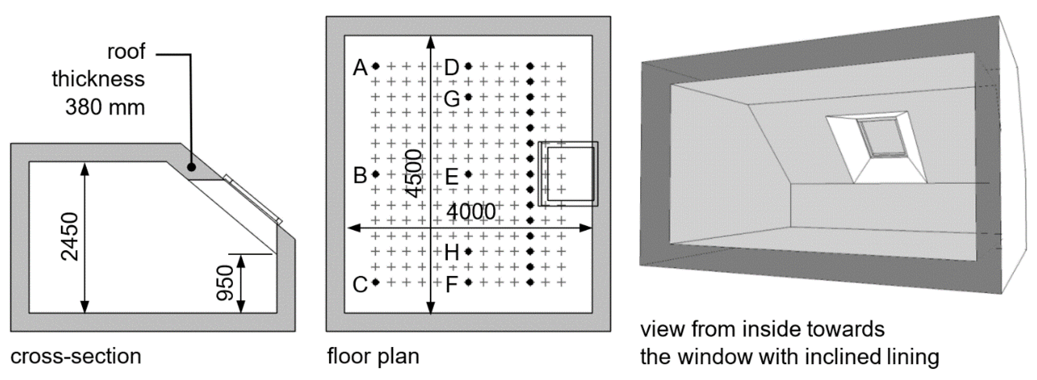
The geometry and dimensions of the studied room represent a typical inhabited attic room (Figure 7). The dimensions of the roof window are 860 × 1180 mm, and its triple glazing has a light transmittance, τ, of 0.74. Except for the floor, all of the internal surfaces are supposed to be painted a bright white with a corresponding light reflectance, ρ, of 0.84. The floor reflectance, ρ, is 0.66 (gray carpet). The reflectance should correspond to the physical model prepared for measurement in Section 3.5. The internal surface coatings of the physical model prepared for daylight measurement in Section 3.4 were selected in order to reproduce such high values of reflectance.
3.4. Daylight Measurements
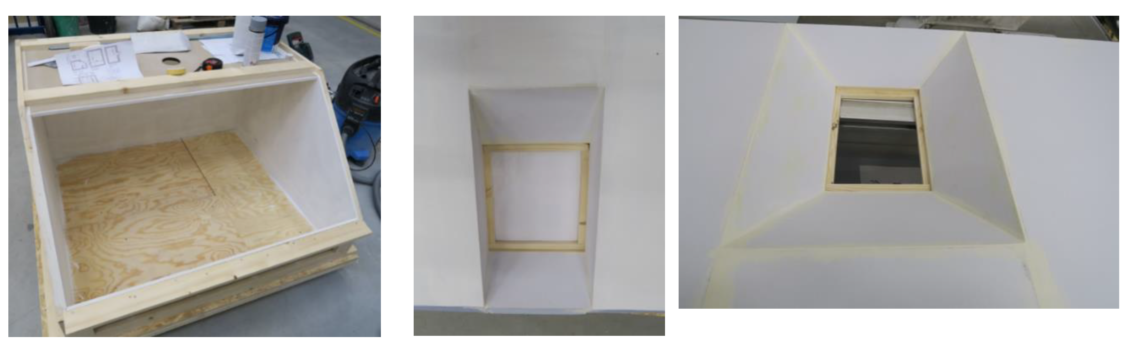
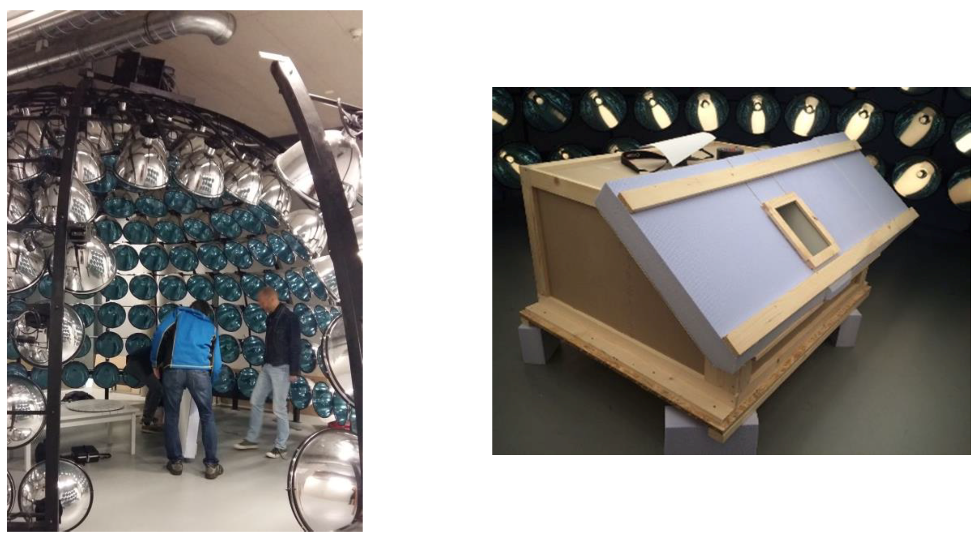
The daylight distribution was measured using a model with a 1:4 scale (Figure 8) in the daylight laboratory in Danube University Krems, Austria. The simulator had a diameter of 6 m (Figure 9). The horizontal daylight level in the middle of the simulator, where the model was placed, was set to 8000 lx. The model of the room had a changeable roof. The roof window was either placed centrally or near to the side partition wall. Additionally, alternatives for different geometries of side lining were analyzed, namely perpendicular and slanted with α = 45°. Surfaces were finished using high-reflectance coatings corresponding to the reflectance values used in the simulation in Section 3.3.
3.5. Formulation of General and Detailed Recommendations
Additionally, as a result of all the analyses, a set of recommendations for the technical design of the roof window was formulated. Moreover, further steps for the implementation of new products were followed, namely (i) the creation of a catalogue of the overall solution and (ii) the support of an independent assessment. Furthermore, a certification body (Centrum stavebního inženýrství a.s., Zlín, Czech Republic) performed measurements of the following mandatory declared parameters [20]: Thermal transmittance, airtightness, and water tightness to wind-driven rain.
4. Results
4.1. Parametric Studies
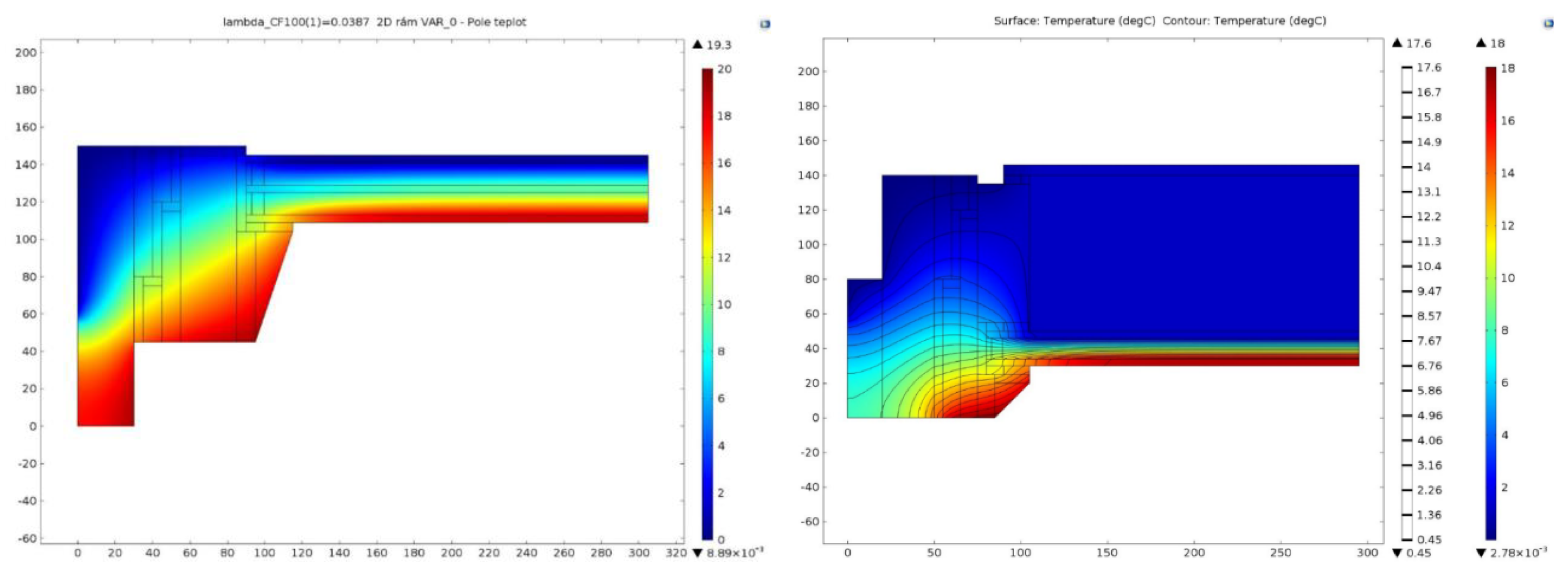
The results of the heat transfer calculations for two different window configurations (see Figure 5) are presented in Figure 10. Configuration A has a higher thermal transmittance of the frame, UF, for the relevant geometries, however, the use of a high-performance glazing at the exterior side leads to an overall lower thermal transmittance of the window compared to configuration B.
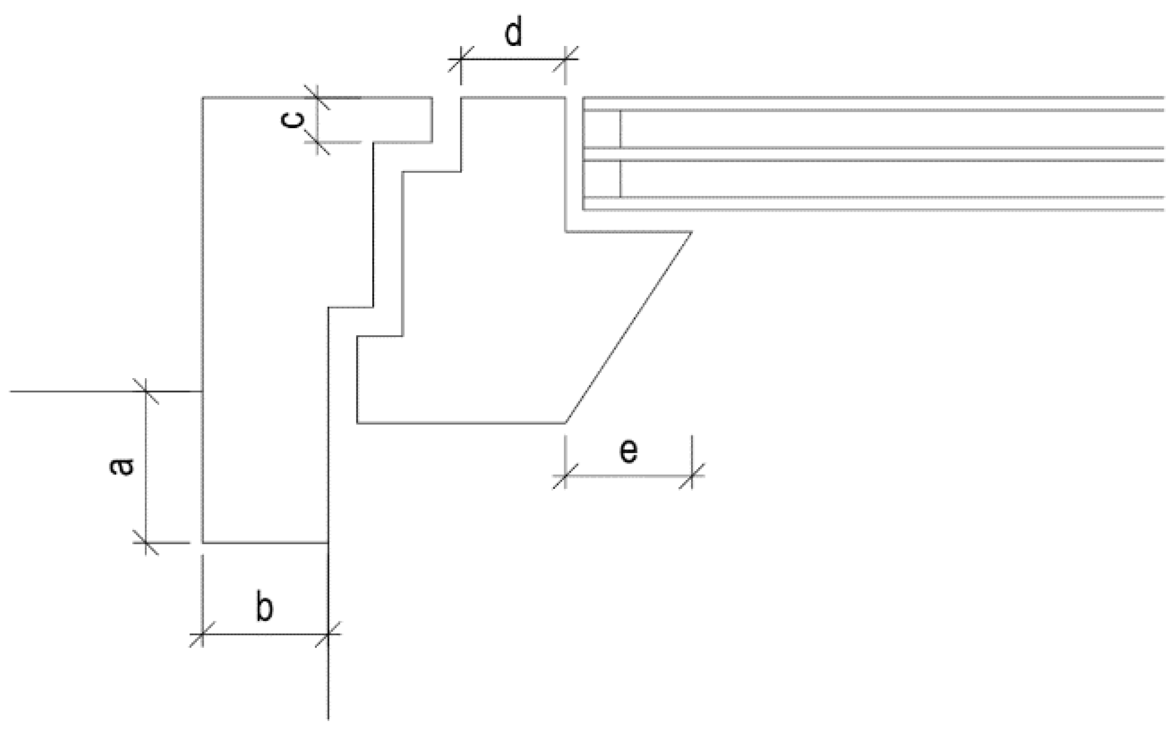
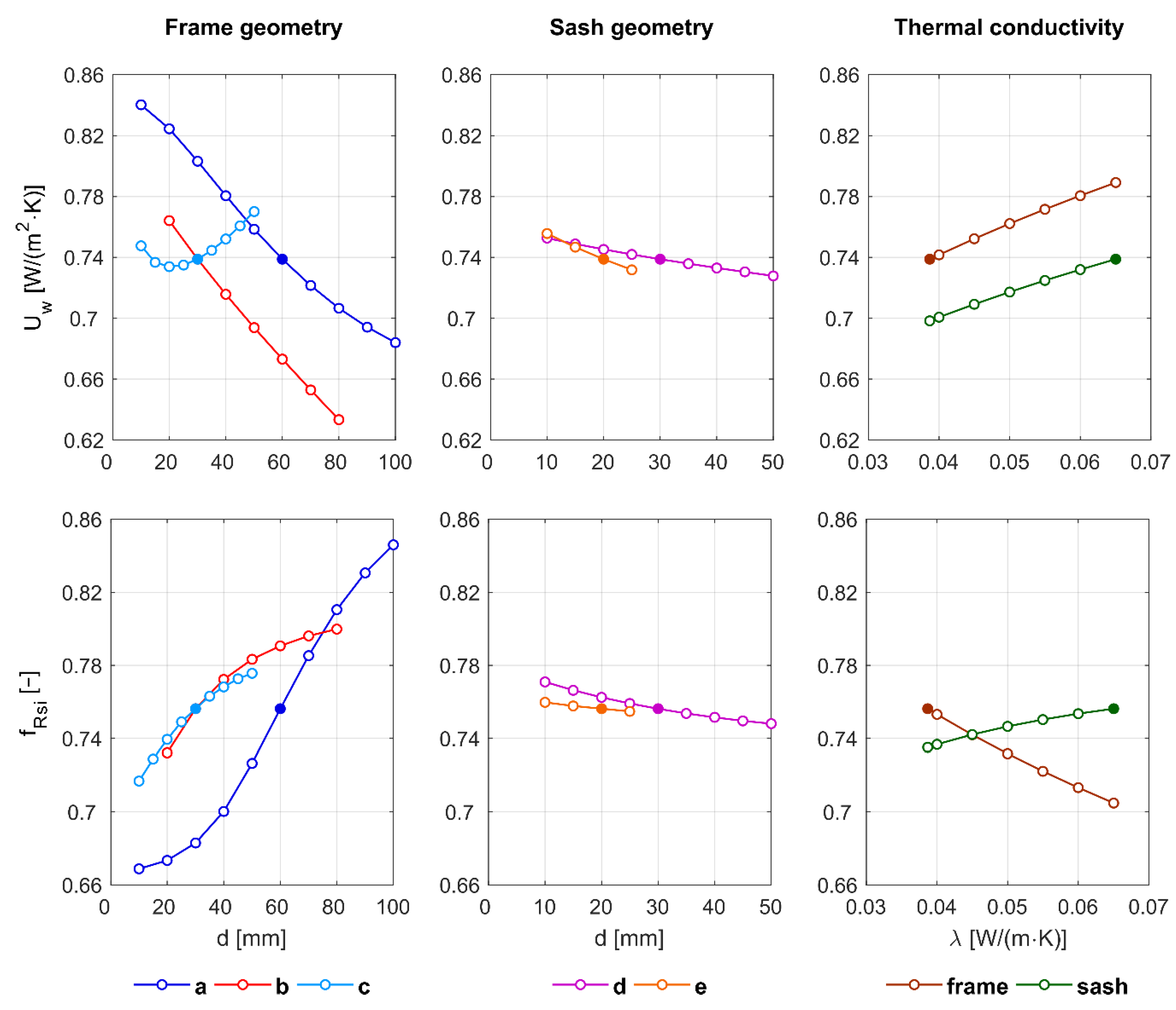
More detailed results of the parametric studies for configuration A are presented in Figure 11 and Figure 12. Each parameter was tested for a wide range of geometries, separately assuming homogeneous material for the frame with very low thermal conductivity. It can be concluded that the most significant parameters are (i) the setting depth of the window frame into the thermally insulated roof layer, (ii) the overall width of the frame and sash, and (iii) the material of the frame and sash. Other material and geometrical parameters are less important. These results were considered in the next developmental steps.
4.2. Real Design Solution
Figure 13 and Figure 14 show the configuration, dimension, and material properties as suggested by the development team for two selected final design variants, considering the results in Section 4.1 and technical limitations. The figures represent the cross-sections over the hinge. The frame and sash were made of a combination of soft wood and hardened plastics. The thermal conductivities used in the 2D calculation are summarized in Table 3. The thermal conductivity of the hardened polystyrene, Compacfoam [25], was measured in accordance with EN 12667 [29] using the HFM 300 apparatus (Linseis GmbH, Selb, Germany) using a sample with a size of 300 mm × 300 mm. The sample, declared as CF100, had a bulk density of 122 kg/m3. The dry thermal conductivity was determined as 0.037 W/(m·K), and the thermal conductivity in the wet state (the moisture content of the water-saturated sample over four weeks was 1.6 m%), λchar, was 0.039 W/(m·K). Other values in Table 3 are taken from the literature. The boundary conditions used in the 2D calculations are summarized in Table 4.
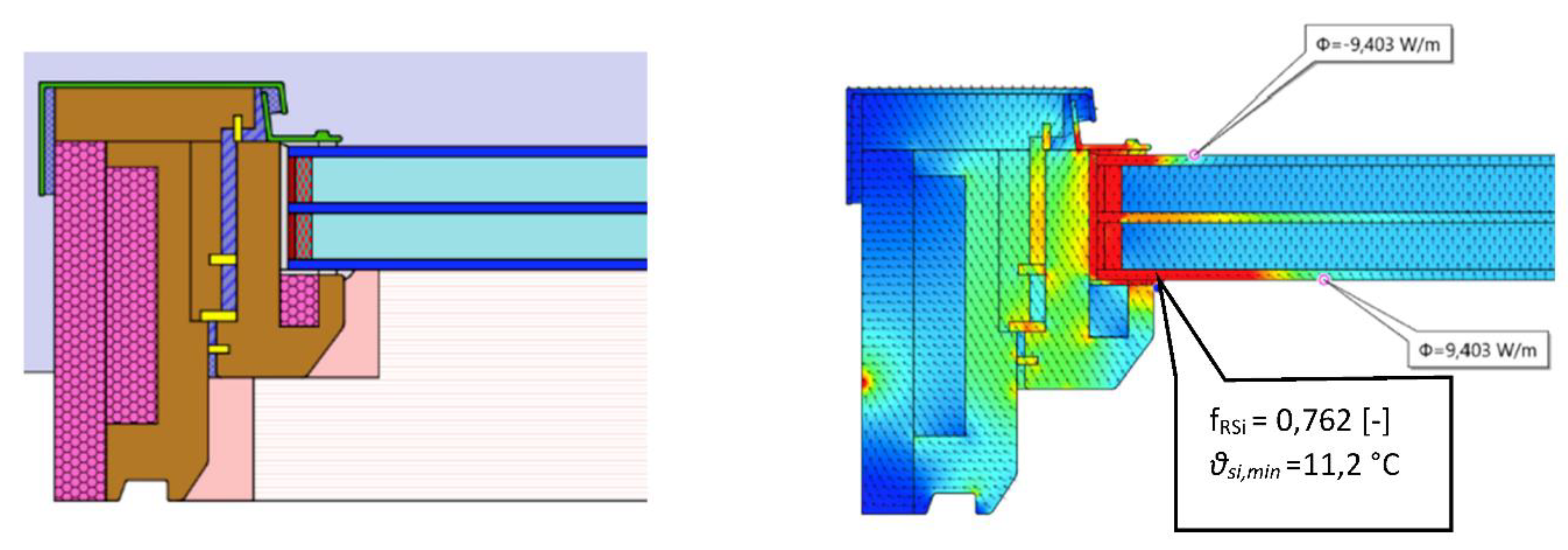
Several types of glazing unit can be used in each design variant. The window in Figure 13 is equipped with triple glazing with a Ug of 0.5 W/(m2·K). The window in Figure 14 has a Ug of 0.3 W/(m2·K), and is equipped with a special glazing unit in which two transparent polyester foils divide the space between two glazing panes into three cavities to reduce the overall heat transfer. For construction reasons, their spacers have a higher thermal conductivity than those used in the best available triple glazing. The thermal performances of the presented window variants are summarized in Table 5.
Table 6 shows the effects of thermal coupling for perpendicular and slanted window linings for variant II. The values of Uw,inst were derived from the calculated thermal transmittance of the window and the linear thermal transmittance at both sides, the sill and the head. The values of ΔU represent the difference between Uw,inst and Uw. A significant influence of thermal coupling is evident. The slanting itself plays a minor role in the heat transfer.
The minimum surface temperature is presented for variant II (Table 7) in the most critical combination: (i) For the slanted lining and (ii) for the glazing unit with a metallic spacer. The lowest surface temperature is still at the edge of the glazing, similar to in the previous calculation without thermal coupling. The values fulfill the requirements (see Figure 4), and therefore the risk of water vapor condensation is minimized.
4.3. Daylight Simulations
Figure 15 shows the calculated daylight factors, D, at the selected control points on the horizontal reference plane 850 mm above the floor level, and the mean daylight factor, Dm, as a function of the window lining inclination, α. By slanting the lining, it is possible to achieve an improvement in the overall level of daylight (expressed in terms of Dm) as well as a significant local improvement in the level of daylight in the area close to the window. Due to the local increase in the daylight factor, a significantly larger portion of the floor area will be available for activities which require higher daylight levels, i.e., D > 1.5%.
4.4. Daylighting Measurements
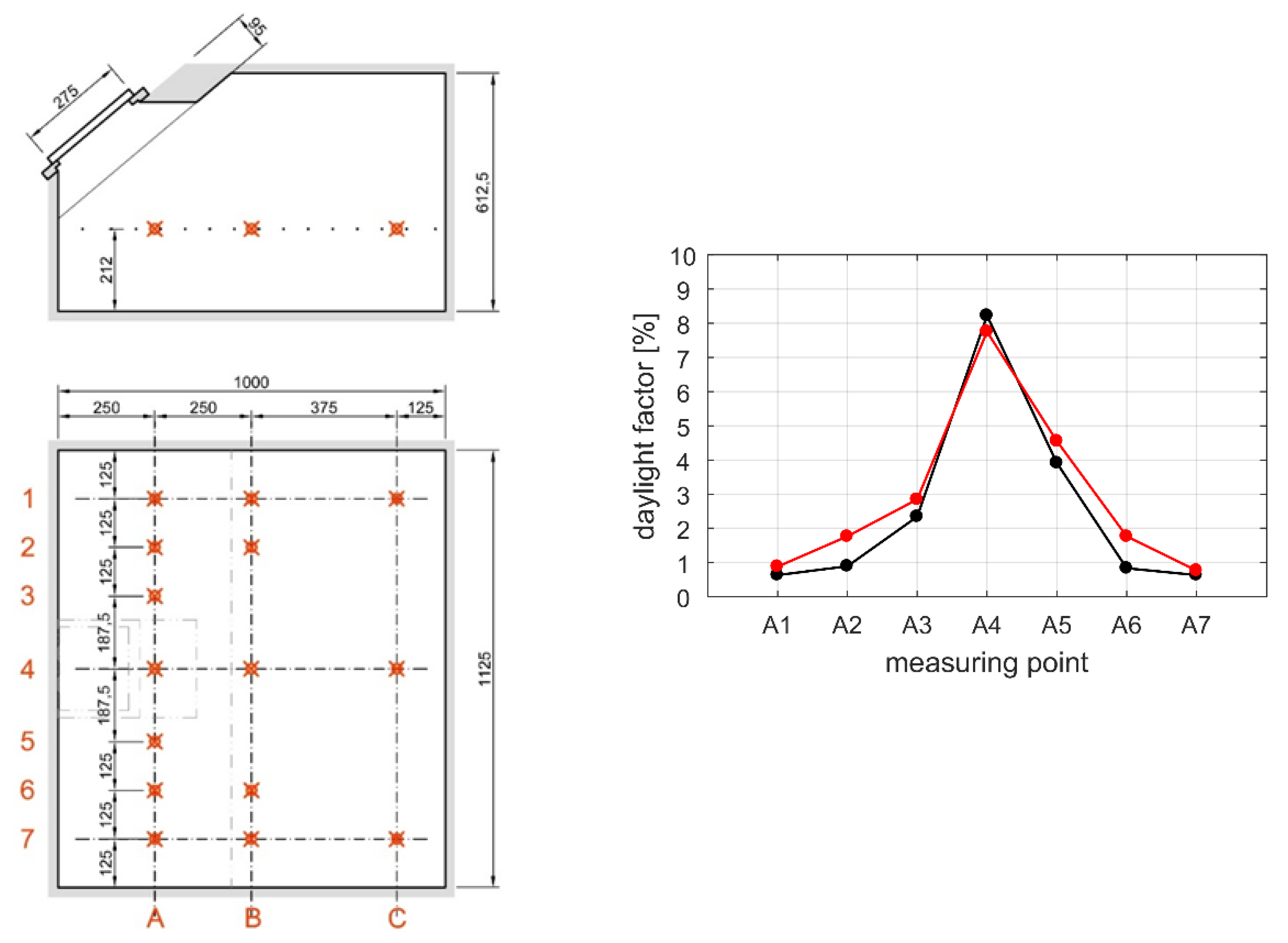
In the model, the values of external and internal illumination at points on the horizontal plane were measured at a height corresponding to measurements on real buildings. Figure 16 shows the results expressed as a daylight factor for a series of points closest to the window (row A) for a perpendicular and slanted side lining. Significant differences in the daylight factor were found for the slanted side lining. Only negligible differences were found in rows B and C.
5. Discussion
This paper illustrates the practical use of building physics tools for studying heat transfer and the daylight situation. The aim was to find a technical solution for roof windows suitable for passive buildings and other energy-optimized buildings in cooperation with an industrial partner. An iterative multilevel process using two-dimensional heat conduction calculations, from initial parametric studies to specific detailed calculations, was applied in collaboration with the development team. The usability of the results for practical window design was discussed at each step of development.
Additionally, a limited degree of verification was performed through measurements in a climatic chamber. Final (formal) verification was achieved through certification by an independent testing laboratory. For practical use, an interactive tool was developed which calculates the resulting thermal transmittance according to the basic selection of the frame and glazing and refers to the elaborated window details to ensure that the surface temperature requirements are met.
The simulated values of thermal transmittance of 0.7 to 0.5 W/(m2·K) can be considered very good results. In any case, the further reduction of heat transmission would be accompanied by an increase in the relative importance of the thermal coupling between the window and roof construction.
Slanted lining has a very positive effect on the quality of daylighting. Measurements made using a physical model in the laboratory show similar tendencies to those observed in simulations, although the simulated results show slightly higher daylight values. It is possible to accept an increase in thermal coupling to some extent. A slant of 30° seems to be a good compromise in the majority of cases.
A higher level of daylight will probably also bring a greater independence from artificial lighting, and thus allow greater energy savings or (hypothetically) possibly the use of smaller roof windows.
In further research, the authors aim to focus on several related tasks:
- (a)
- The risk of overheating. Overheating and/or cooling energy demand of attic rooms and, in this context, the possibility of advanced controlled shading of roof windows [30].
- (b)
- 3D heat transfer models. Due to the fact that windows contain parts for which it is not possible to perform a 2D calculation, especially in corners, it might be useful to use the 3D calculation of a whole window including coupling, taking advantage of the symmetry. However, to achieve this, some simplifications would have to be made, for example, for the opening mechanism, handle, and eventually ventilation flaps.
- (c)
- Values of the heat transfer between the local surface and surroundings. Aside from the complexity of the calculations, the results were further burdened by uncertainties regarding the boundary conditions. Very detailed studies of heat transfer near to the surfaces of roof windows are needed.
Author Contributions
J.T., as a head of the project, was responsible for the general methodology and writing the paper. V.C. performed the 2D parametric studies and heat transfer evaluation. J.N. performed the daylighting simulations. K.S. supported the development of the project by making thermal performance measurements. L.M. was responsible for daylight measurements.
Funding
This research was funded by the Ministry of Education, Youth and Sports, Czech Republic, grant number LO1605.
Acknowledgments
This work was supported by the Ministry of Education, Youth and Sports, Czech Republic, within National Sustainability Programme I (NPU I), project LO1605—University Centre for Energy Efficient Buildings—Sustainability Phase. Our special thanks go to Slavona Company for its inspiring cooperation and support. We also thank for the cooperation of the daylighting laboratory at Danube University in Krems, Austria.
Conflicts of Interest
The authors declare no conflict of interest.
Nomenclature
| A | Area, m2 |
| D | Daylight factor, % |
| U | Thermal transmittance, W/(m2·K) |
| f | Surface temperature factor, dimensionless |
| g | Solar factor, dimensionless |
| h | Surface heat transfer coefficient, W/(m2·K) |
| l | Length, m |
| ψ | Linear thermal transmittance, W/(m·K) |
| ρ | Light reflectance, dimensionless |
| τ | Light transmittance, dimensionless |
| Indices | |
| a | Air |
| c | Convection |
| g | Glazing |
| e | Exterior |
| f | Frame |
| i | Interior |
| inst | Installed |
| r | Radiation |
| s, S | Surface |
| R | Required |
| w | Window |
Appendix A

Table A1.
Examples of the distribution of transmittance heat loss for a pitched roof (total area 140 m2) of a family house with six roof windows (6 × 1.0 m2). Alternative A corresponds to a typical solution around the year 2000, alternative B corresponds to a passive house quality roof with traditional roof windows, and alternative C corresponds to a passive house quality with high-performance windows.
| Thermal Transmittance | Heat Transfer Coefficient | Increased Heat Transfer (%) (100% = No Windows) | |||
|---|---|---|---|---|---|
| (W/K) | (%) | ||||
| A | |||||
| Roof | 0.3 W/(m2·K) | 40.2 | 69 | 69 | |
| Roof windows | 1.8 W/(m2·K) | 10.8 | 19 | 31 | |
| Window–roof thermal coupling | 0.3 W/(m·K) | 7.2 | 12 | ||
| Total | 58.2 | 100 | 139 | ||
| B | |||||
| Roof | 0.1 W/(m2·K) | 13.4 | 49 | 49 | |
| Roof windows | 1.5 W/(m2·K) | 9.0 | 33 | 51 | |
| Window–roof thermal coupling | 0.2 W/(m·K) | 4.8 | 18 | ||
| Total | 27.2 | 100 | 194 | ||
| C | |||||
| Roof | 0.1 W/(m2·K) | 13.4 | 71 | 71 | |
| Roof windows | 0.6 W/(m2·K) | 3.6 | 19 | 29 | |
| Window–roof thermal coupling | 0.08 W/(m·K) | 1.9 | 10 | ||
| Total | 18.9 | 100 | 135 | ||
Appendix B. Results of Observations of Heat Transfer at an Internal Surface under Real Conditions—Preliminary Comparison of a Large Vertical Window and a Small Roof Window (Case Study)
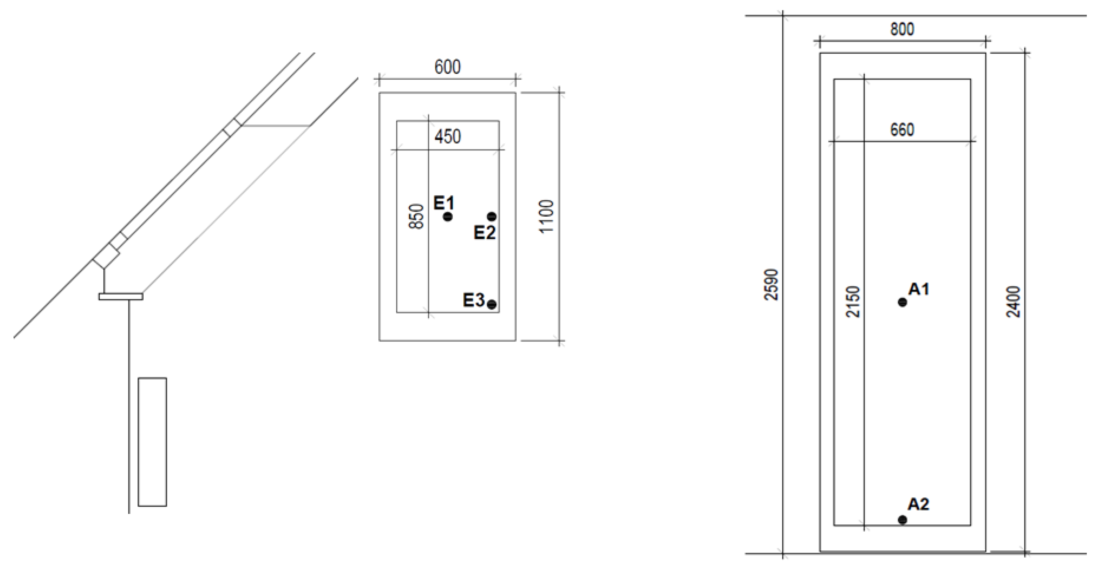
Two windows in an occupied family house were monitored for heat transfer between the interior glazing and the surroundings. There were two principally different situations: (a) A roof window with standard double glazing and with dimensions of 0.86 m × 0.61 m fitted in an insulated sloping roof; and (b) a balcony door containing a glazed window with dimensions of 2.4 m × 0.8 m, with visible glazing dimensions of 2.15 m × 0.66 m. Under the roof window is a heating body (a hot water radiator) reaching up to half the width of the window. The room with a balcony door has a high-quality envelope at the passive house level [5]; the windows here are equipped with triple glazing. There is no heating body at the balcony door.
In both cases, the values of the heat flux density, the temperature at the surface of the glass, and the temperatures at a small distance from the surface were measured at selected locations (Figure A1).
Figure A1.
Schematic of a roof window (left) and a glazed balcony door (right). Points A1, A2, E1, E2, and E3 indicate where the surface heat transfer coefficient was preliminarily estimated. (Unit: mm).
Figure A1.
Schematic of a roof window (left) and a glazed balcony door (right). Points A1, A2, E1, E2, and E3 indicate where the surface heat transfer coefficient was preliminarily estimated. (Unit: mm).

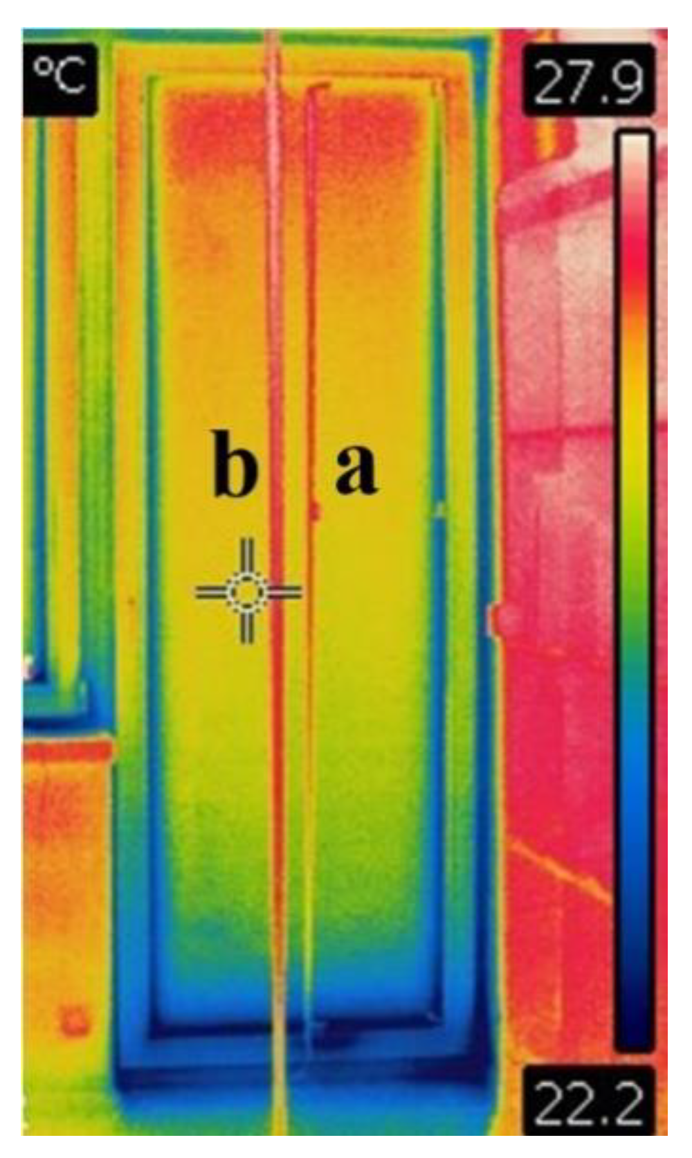
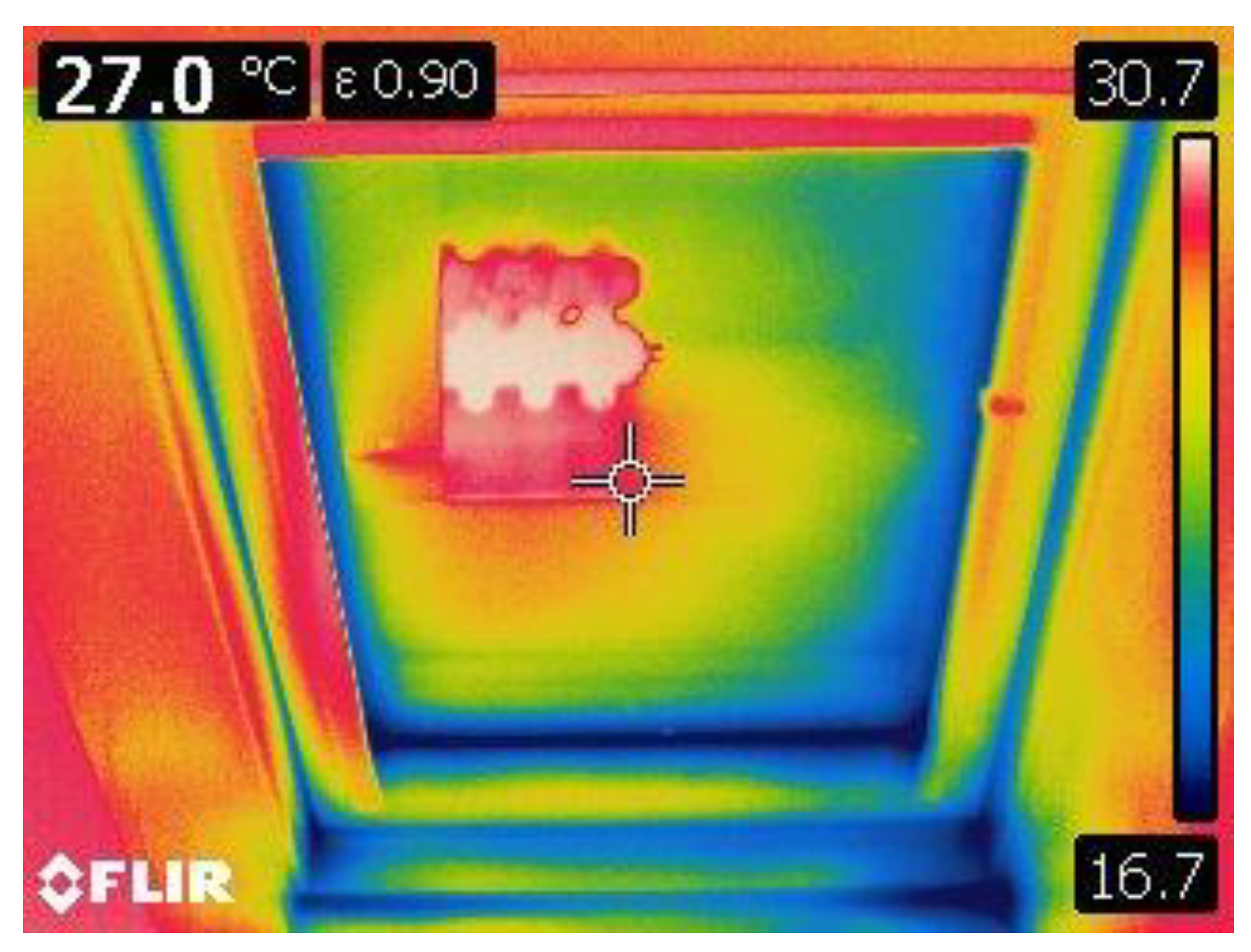
Figure A2 is an infrared image of a balcony door, with a relatively uniform drop in surface temperatures from the top downwards, more pronounced at the bottom, over a height of approximately 200 mm. The air in this room has very little thermal stratification (up to 1.6 K at a height corresponding to the height of the window). Figure A3 is an infrared image of a roof window showing unevenness in the surface temperature distribution, including an apparent direct exposure of the heating body (surface temperature at heating body top by 50 °C).
Figure A2.
Illustrative infrared picture of a glazed balcony door. a: a thin textile ribbon installed 15 mm in front of the glazing surface; b: a thin textile ribbon at a distance of 1.4 m from the glazing. Both ribbons were used for indirect informative measurement of the temperature of the surrounding air.

Figure A3.
Illustrative infrared picture of a roof window. A multiple reflection of a heating body is clearly visible, which affects the window, in particular the radiative heat transfer component.
Figure A3.
Illustrative infrared picture of a roof window. A multiple reflection of a heating body is clearly visible, which affects the window, in particular the radiative heat transfer component.

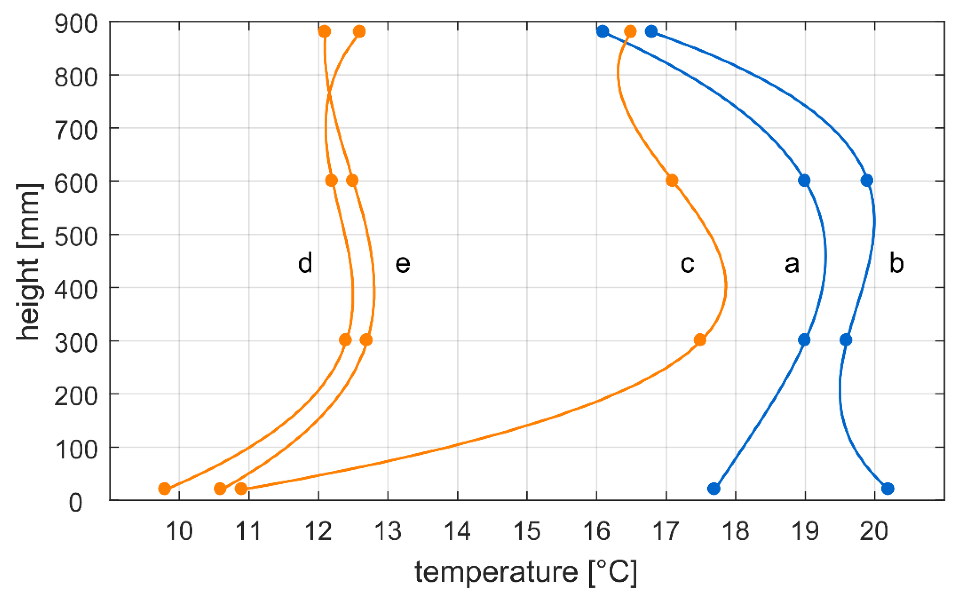
The complicated situation in the immediate vicinity of the roof window is also reflected by a number of other air temperature measurements made at different distances from the window (Figure A4). This is demonstrated by the presence of inhomogeneous turbulent air streams with temperatures that are very different from the air temperature measured in the middle of the room. Air temperatures near the surface are approximately 2 to 5 K higher when the heating body is in normal operation than in the case when the upwards heat exchange is blocked. Figure A5 clearly shows the effect of the heating body on the surface and air temperature in the layer close to the window surface. In cases with an unblocked heating body function, the temperature at the window surface and its surroundings is higher than the air temperature in the center of the room.
Figure A4.
Illustrative single temperature measurement for the roof window—vertical temperature profile along the window. a: a distance of 15 mm from the glazing. b: a distance of 80 mm from the glazing. c, d, and e: glass temperature in the center of the window, at the left edge of the window, and at the right edge of the window, respectively. The indoor air temperature was 21.5 °C, the surface temperature of the heating body was 27 °C, and the exterior air temperature was 0 °C.

Figure A5.
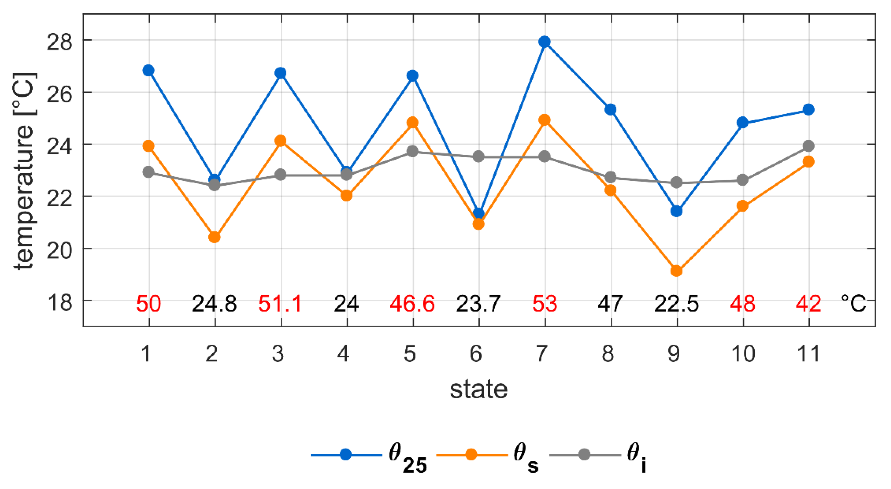
Measured temperatures in the center of the roof window for different states of the heating body. θ25 is the temperature at a distance of 25 mm from the surface, θs is the temperature at the surface, and θi is the air temperature at the center of the room. The temperature of the heating body is shown in the bottom row.
Figure A5.
Measured temperatures in the center of the roof window for different states of the heating body. θ25 is the temperature at a distance of 25 mm from the surface, θs is the temperature at the surface, and θi is the air temperature at the center of the room. The temperature of the heating body is shown in the bottom row.

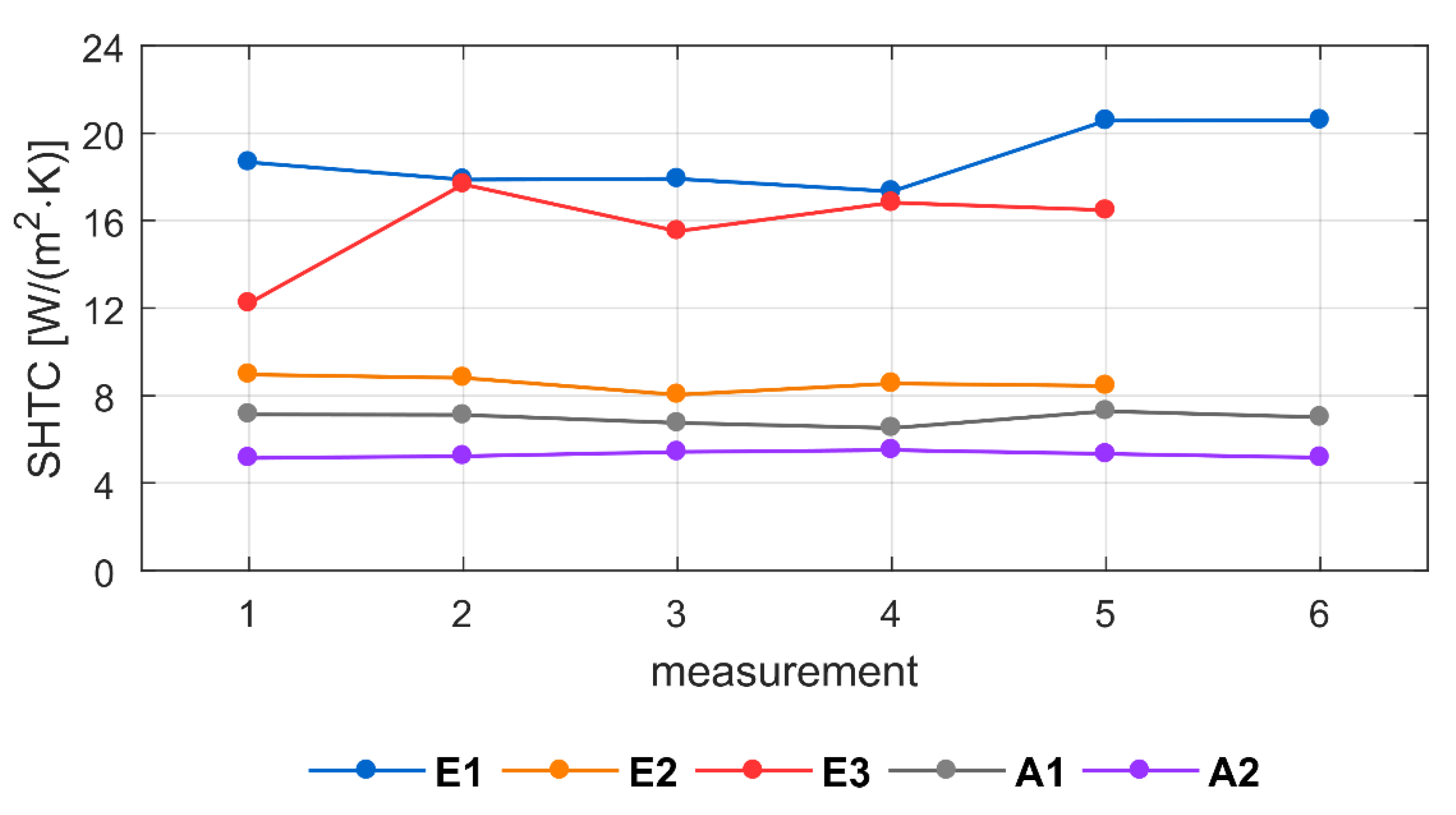
An evaluation of the surface heat transfer coefficient from the heat flow density measurements and the temperature differences between the air and the window surface is presented in Figure A6 and Table A2. The surface heat transfer coefficient of the balcony door generally corresponds well to the expected value (standard value hsi = 1/0.13 W/(m2·K)). For the roof window, the corresponding value of this method, proven by the measurement of the balcony door, seems to be quite different, being up to twice as high as the value in the center of the window.
The studied case is not representative of other possible configurations of roof windows (due to the presence of a heating body, different window size, different geometry of the side lining, etc.). Further measurements in laboratory conditions and other analyses should be used to study this effect more precisely.
Figure A6.
Surface heat transfer coefficient (SHTC; hsi) estimated from preliminary measurements at the roof window and the balcony door window (see Figure A1).
Figure A6.
Surface heat transfer coefficient (SHTC; hsi) estimated from preliminary measurements at the roof window and the balcony door window (see Figure A1).

Table A2.
Surface heat transfer coefficient—overview of measured values.
| Window | Position | Mean Value hsi W/(m2·K) | |
|---|---|---|---|
| Glazed balcony door | Center | A1 | 7.0 |
| Bottom | A2 | 5.3 | |
| Roof window | Center | E1 | 18.8 |
| Center, right | E2 | 8.6 | |
| Bottom, right edge | E3 | 15.7 | |
References
- Hens, H. Building Physics. Heat, Air and Moisture. Fundamentals and Engineering Methods with Examples and Exercises; Wilhelm Ernst & Sohn: Berlin, Germany, 2012. [Google Scholar]
- European Committee for Standardization. Set of European Standards in Responsibility of CEN TC89 Thermal Performance of Buildings and Building Components; European Committee for Standardization (CEN): Brussels, Belgium, 2019. [Google Scholar]
- Technological Agency of the Czech Republic. Project TH01021120 SONG—Střešní Okna Nové Generace (Skylights of New Generation). Technological Agency of the Czech Republic: Prague, Czech Republic; Available online: https://www.uceeb.cz/projekty/stresni-okna-nove-generace (accessed on 16 June 2019).
- Schnieders, J.; Feist, W.; Rongen, L. Passive Houses for different climate zones. Energy Build. 2015, 105, 71–87. [Google Scholar] [CrossRef]
- Kriterien für den Passivhaus-, EnerPHit- und PHI-Energiesparhaus-Standard. Passivhaus Institut. Available online: https://passiv.de/downloads/03_zertifizierungskriterien_gebaeude_de.pdf (accessed on 1 March 2019).
- Grove-Smith, J.; Aydin, V.; Feist, W.; Schnieders, J.; Thomas, S. Standards and policies for very high energy efficiency in the urban building sector towards reaching the 1.5 degrees C target. Curr. Opin. Environ. Sustain. 2018, 30, 103–114. [Google Scholar] [CrossRef]
- The New Passive House Classes. Available online: https://passipedia.org/certification/passive_house_categories (accessed on 1 March 2019).
- D’Agostino, D.; Mazzarella, L. What is a nearly zero energy building? Overview, implementation and comparison of definitions. J. Build. Eng. 2019, 21, 200–212. [Google Scholar] [CrossRef]
- Erhorn-Kluttig, H.; Erhorn, H.; Reiss, J. Plus energy—A new energy performance standard in Germany for both residential and non-residential buildings. Adv. Build. Energy Res. 2015, 9, 73–88. [Google Scholar] [CrossRef]
- Informationen, Kriterien und Algorithmen für Zertifizierte Passivhaus Komponenten: Transparente Bauteile und Öffnungselemente in der Gebäudehülle. Available online: http://www.passiv.de/downloads/03_zertifizierungskriterien_transparente_bauteile.pdf (accessed on 1 March 2019).
- Gustavsen, A.; Arasteh, D.; Jelle, B.P.; Curcija, C.; Kohler, C. Developing low conductance window frames: Capabilities and limitations of current window heat transfer design tools—State-of-the-art review. J. Build. Phys. 2008, 32, 131–153. [Google Scholar] [CrossRef]
- Okna stresni, zateplovací sada thermos. Available online: https://www.oknastresni.cz/zatepleni-oken/zateplovaci-sada-thermos (accessed on 20 October 2018).
- Component Database. Roof Windows. Passivhaus Institut. Available online: https://database.passivehouse.com/de/components/list/roof_window (accessed on 1 March 2019).
- European Committee for Standardization. EN 673 Glass in Buildings; European Committee for Standardization (CEN): Brussels, Belgium, 2011. [Google Scholar]
- Van de Bossche, N.; Buffe, L.; Janssens, A. Thermal optimization of window frames. In Proceedings of the 6th International Building Physics Conference, IBPC 2015, Torino, Italy, 14–17 June 2015; Volume 78. [Google Scholar]
- Misiopecki, C.; Bouquin, M.; Gustavsen, A.; Jelle, B.P. Thermal modeling and investigation of the most energy-efficient window position. Energy Build. 2018, 158, 1079–1086. [Google Scholar] [CrossRef]
- European Committee for Standardization. EN ISO 13789 Thermal Performance of Buildings—Transmission and Ventilation Heat Transfer Coefficients—Calculation Method; European Committee for Standardization (CEN): Brussels, Belgium, 2018. [Google Scholar]
- UNMZ. CSN 73 0540-2 2011 Thermal Protection of Buildings. Part 2—Requirements; UNMZ: Prague, Czech Republic, 2011. [Google Scholar]
- Tywoniak, J.; Staněk, K.; Calta, V. Roof windows for passive houses what can be improved? In Proceedings of the 7th International Building Physics Conference IBPC 2018, Syracuse, NY, USA, 23–26 September 2018; Syracuse University: Syracuse, NY, USA, 2018; pp. 1449–1454. [Google Scholar]
- European Committee for Standardization. EN 14351-1 Windows and EXTERNAL Pedestrian Doorsets without Resistance to Fire and/or Smoke Leakage; European Committee for Standardization (CEN): Brussels, Belgium, 2018. [Google Scholar]
- European Committee for Standardization. EN ISO 12567-2. Thermal Performance of Windows and Doors—Determination of Thermal Transmittance by Hot Box Method—Part 2: Roof Windows and other Projecting Windows; European Committee for Standardization (CEN): Brussels, Belgium, 2006. [Google Scholar]
- COMSOL Multiphysics 4.4. Available online: https://www.comsol.com (accessed on 5 March 2016).
- European Committee for Standardization. EN ISO 10077-2 Thermal Performance of Windows, Doors and Shutters—Calculation of Thermal Transmittance—Part 2: Numerical Method for Frames; European Committee for Standardization (CEN): Brussels, Belgium, 2017. [Google Scholar]
- Svend, S.; Lautsen, J.B.; Kragh, J. Linear thermal transmittance of the assembly of the glazing and the frame in windows. In Proceedings of the 7th Symposium on Building Physics in the Nordic, Reykjavik, Iceland, 13–15 June 2005; IBRI: Reykjavik, Iceland, 2005; pp. 995–1002. [Google Scholar]
- Compacfoam. Available online: http://www.compacfoam.at (accessed on 20 April 2019).
- Software HTflux. Available online: https://www.htflux.com (accessed on 20 January 2019).
- European Committee for Standardization. EN ISO 10211 Thermal Bridges in Building Construction—Heat Flows and Surface Temperatures—Detailed Calculations; European Committee for Standardization (CEN): Brussels, Belgium, 2018. [Google Scholar]
- Velux Daylight Visualiser. Available online: https://www.velux.com/article/2016/daylight-visualizer (accessed on 20 January 2019).
- European Committee for Standardization. EN ISO 12667 Thermal Performance of Building Materials and Products. Determination of Thermal Resistance by Means of Guarded Hot Plate and Heat Flow Meter Methods. Products of High and Medium Thermal Resistance; European Committee for Standardization (CEN): Brussels, Belgium, 2001. [Google Scholar]
- Intellectual Property Office. Exterior Shading System with Integrated Functions for Roof Windows; Utility Model CZ 32088; Intellectual Property Office: Prague, Czech Republic, 2018. [Google Scholar]
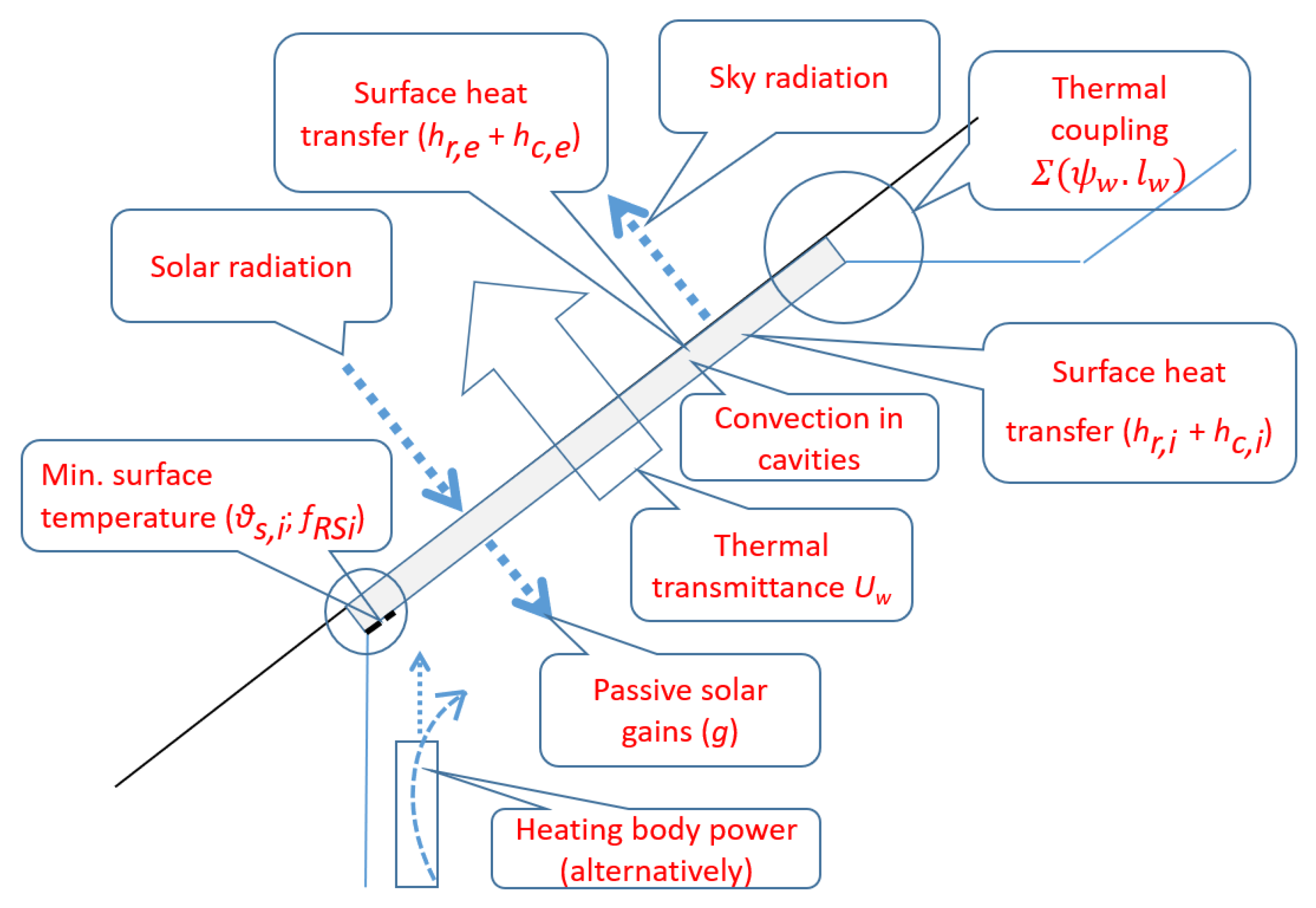
Figure 1.
Significant thermal phenomena related to roof windows.

Figure 2.
Schematic horizontal cross-section of a typical position of a roof window in a pitched roof. ext.: exterior air temperature; int: interior air temperature.
Figure 2.
Schematic horizontal cross-section of a typical position of a roof window in a pitched roof. ext.: exterior air temperature; int: interior air temperature.

Figure 3.
The result of a preliminary calculation for a (hypothetical) roof window of excellent quality. Heat transfer (left) and heat transfer including the effect of installation on roof thermal coupling (right) based on 2D calculations for all relevant cross-sections [19].
Figure 3.
The result of a preliminary calculation for a (hypothetical) roof window of excellent quality. Heat transfer (left) and heat transfer including the effect of installation on roof thermal coupling (right) based on 2D calculations for all relevant cross-sections [19].

Figure 4.
Minimum values of the surface temperature factor to avoid water vapor condensation (left) and mold growth (right) assuming an interior air temperature of 20 °C for different air humidity.
Figure 4.
Minimum values of the surface temperature factor to avoid water vapor condensation (left) and mold growth (right) assuming an interior air temperature of 20 °C for different air humidity.

Figure 5.
Configuration A (left) and alternative configuration B (right) that were tested in parametric studies. a: adiabatic condition [23].
Figure 5.
Configuration A (left) and alternative configuration B (right) that were tested in parametric studies. a: adiabatic condition [23].

Figure 6.
A cross-section through the roof window showing the inclination (slanting; α) of the window lining.
Figure 6.
A cross-section through the roof window showing the inclination (slanting; α) of the window lining.

Figure 7.
The geometry of the room studied for daylighting distribution (letters represent the control points for investigation). (Unit: mm).
Figure 7.
The geometry of the room studied for daylighting distribution (letters represent the control points for investigation). (Unit: mm).

Figure 8.
Model of a room for daylight measurement with changeable pitched roof.

Figure 9.
Experimental setup for daylight measurement in a laboratory.

Figure 10.
Temperature distribution for window configuration A (left) and B (right).

Figure 11.
Schematic of a window cross-section showing the most important parameters analyzed in parametric studies.
Figure 11.
Schematic of a window cross-section showing the most important parameters analyzed in parametric studies.

Figure 12.
Key tendencies discovered in the parametric studies, expressed as the thermal transmittance of the whole window and as the surface temperature factor. Filled points represent basis values. For legend, see Figure 11.
Figure 12.
Key tendencies discovered in the parametric studies, expressed as the thermal transmittance of the whole window and as the surface temperature factor. Filled points represent basis values. For legend, see Figure 11.

Figure 13.
Schematic cross-section of the window variant, I, with triple glazing (left) and calculated heat flux distribution (right).
Figure 13.
Schematic cross-section of the window variant, I, with triple glazing (left) and calculated heat flux distribution (right).

Figure 14.
Schematic cross-section of the window variant, II, with special glazing using two foils to divide the cavity between two glazing panes (left) and calculated heat flux distribution (right).
Figure 14.
Schematic cross-section of the window variant, II, with special glazing using two foils to divide the cavity between two glazing panes (left) and calculated heat flux distribution (right).

Figure 15.
The results of the daylight calculation as a function of the lining inclination. The daylight factor at selected control points (see Figure 7) and the mean value (Dm) (left) and daylight factors in the line of control points at a distance of 1 m from the external wall (right).
Figure 15.
The results of the daylight calculation as a function of the lining inclination. The daylight factor at selected control points (see Figure 7) and the mean value (Dm) (left) and daylight factors in the line of control points at a distance of 1 m from the external wall (right).

Figure 16.
Laboratory-measured values of the daylight factor. Measured points (left) and values for points A1 to A7 (right). The black line represents the perpendicular side-lining and the red line represents the slanted side-lining with a slant angle of 45°. (Unit: mm).
Figure 16.
Laboratory-measured values of the daylight factor. Measured points (left) and values for points A1 to A7 (right). The black line represents the perpendicular side-lining and the red line represents the slanted side-lining with a slant angle of 45°. (Unit: mm).

Table 1.
Standard values of linear thermal transmittance, (W/(m·K)), as a result of thermal couplings. Adapted from the Czech national standard [18].
Table 1.
Standard values of linear thermal transmittance, (W/(m·K)), as a result of thermal couplings. Adapted from the Czech national standard [18].
| Required | Recommended | Recommended for Passive Buildings | |
|---|---|---|---|
| Window in wall | 0.1 | 0.03 | 0.01 |
| Window in pitched roof | 0.3 | 0.1 | 0.02 |
Table 2.
Standard values of thermal transmittance, Uw (W/(m2·K)), adapted from the Czech national standard [18].
Table 2.
Standard values of thermal transmittance, Uw (W/(m2·K)), adapted from the Czech national standard [18].
| Required | Recommended | Recommended for Passive Buildings | |
|---|---|---|---|
| Window in wall | 1.5 | 1.2 | Range: 0.8–0.6 |
| Window in pitched roof | 1.4 | 1.1 | 0.9 |
Table 3.
Material properties used in the 2D heat transfer calculation.
| Material | Thermal Conductivity, λ (W/(m·K)) | Pattern According to Figure 13 and Figure 14 |
|---|---|---|
| Glazing pane | 1.00 |  |
| Seals (EPDM profiles) | 0.25 |  |
| Wood (soft) | 0.12 |  |
| Compacfoam | 0.039 |  |
| Aerogel | 0.014 |  |
| Extruded polystyrene | 0.032 |  |
Table 4.
Boundary conditions and heat flux scale used in the 2D heat transfer calculations.
| Boundary Condition | Air Temperature θ (°C) | Surface Heat Transfer Resistance Rsi (m2K/W) |
|---|---|---|
| Interior—Building construction | 20 | 0.10 |
| Interior—Window | 20 | 0.13 |
| Interior—Edges of window | 20 | 0.20 |
| Interior—Edges of window for the evaluation of minimum surface temperature | 20 | 0.25 |
| Exterior | −17 | 0.04 |
| Ventilated cavity connected to the exterior (under roof covering) | −17 | 0.10 |
| Variant | Heat Transfer Coefficient (W/K) | Mean Linear Thermal Transmittance for Glazing Edge (W/m·K) ψg | Thermal Transmittance for Reference Window Size (W/(m2·K)) | |||
|---|---|---|---|---|---|---|
| Glazing HT,g | Frame HT,f | Edge HT,ψ,g | ||||
| UF | UW | |||||
| I | 0.530 | 0.503 | 0.103 | 0.025 | 0.94 | 0.71 |
| II | 0.303 | 0.344 | 0.148 | 0.037 | 0.59 | 0.50 |
Table 6.
Effects of thermal coupling for the perpendicular and slanted linings.
| Perpendicular Lining | Slanted Lining (α = 45°) | ||||
|---|---|---|---|---|---|
| ψw (W/(m·K)) | Uw,inst (W/(m2·K)) | ΔU (W/(m2·K)) | ψw (W/(m·K)) | Uw,inst (W/(m2·K)) | ΔU (W/(m2·K)) |
| 0.071 | 0.72 | 0.22 | 0.093 | 0.79 | 0.29 |
Table 7.
Minimum surface temperature and surface temperature factor for variant II, coupled to the roof structure. Slanted lining, indoor temperature of 20 °C, exterior temperature of −17 °C.
Table 7.
Minimum surface temperature and surface temperature factor for variant II, coupled to the roof structure. Slanted lining, indoor temperature of 20 °C, exterior temperature of −17 °C.
| Area | Minimum Surface Temperature θsi,min (°C) | Surface Temperature Factor fRsi (-) |
|---|---|---|
| Sill | 10.8 | 0.752 |
| Head | 11.0 | 0.756 |
| Side lining | 10.9 | 0.755 |
© 2019 by the authors. Licensee MDPI, Basel, Switzerland. This article is an open access article distributed under the terms and conditions of the Creative Commons Attribution (CC BY) license (http://creativecommons.org/licenses/by/4.0/).
Share and Cite
MDPI and ACS Style
Tywoniak, J.; Calta, V.; Staněk, K.; Novák, J.; Maierová, L. The Application of Building Physics in the Design of Roof Windows. Energies 2019, 12, 2300. https://0-doi-org.brum.beds.ac.uk/10.3390/en12122300
AMA Style
Tywoniak J, Calta V, Staněk K, Novák J, Maierová L. The Application of Building Physics in the Design of Roof Windows. Energies. 2019; 12(12):2300. https://0-doi-org.brum.beds.ac.uk/10.3390/en12122300
Chicago/Turabian StyleTywoniak, Jan, Vítězslav Calta, Kamil Staněk, Jiří Novák, and Lenka Maierová. 2019. "The Application of Building Physics in the Design of Roof Windows" Energies 12, no. 12: 2300. https://0-doi-org.brum.beds.ac.uk/10.3390/en12122300
Note that from the first issue of 2016, this journal uses article numbers instead of page numbers. See further details here.