The Application of Molten Salt Energy Storage to Advance the Transition from Coal to Green Energy Power Systems


Department of Power Engineering and Turbomachinery, Silesian University of Technology, 44-100 Gliwice, Poland
*
Author to whom correspondence should be addressed.
Energies 2020, 13(9), 2222; https://0-doi-org.brum.beds.ac.uk/10.3390/en13092222
Submission received: 9 April 2020
/
Revised: 27 April 2020
/
Accepted: 28 April 2020
/
Published: 2 May 2020
(This article belongs to the Special Issue Advanced Mathematical Modeling Technology for Heat Storage and Conversion Systems)
Abstract
:The paper presents technical solutions for a power grid that undergoes the elimination of a significant number of coal-based power generating units. The purpose of the solutions is to adapt the existing machines with sufficient lifespans to the new operating conditions. In particular these include steam turbines. The steam turbines’ cycles may be extended with energy storage systems based on a molten salt. This allows to increase the flexibility of the power generating units while maintaining the largest possible efficiency of the power generation. The solutions presented here allow to connect the steam turbines cycles to renewable energy sources and reduce the overall number of the units that create the fundamental layer of the power grid. The analysis of the solutions involves numerical modeling. The paper describes the assumptions and the results of the modeling for chosen cases of the modernization. The researched considered a number of options that differed in the investment costs and the resulting performance.
1. Introduction
According to the current policies in the power generation industry the energy systems should increase the share of the renewables in the generation of the electric power. A transition from a coal-based system to a green energy one is a complex and a very challenging task. It should be conducted with the upmost respect to the local operating conditions of the machines. A key issue is how to introduce the renewables into the power grid while maintaining its stability.
There are two principal issues in that matter. The first one is how to build a reliable foundation for the power grid with the lowest possible harmful impact on the natural environment. The presence of the foundation is necessary due to the specific way the renewable energy sources operate, which depends strongly on the environmental conditions. This is especially important for wind and solar energy. For safety reasons power grids must be able to compensate for any drops in the power generated by the renewable energy sources. In the countries where power grids have relied on fossil- fueled plants it is natural and economically justified due to the investment costs paid so far to maintain the foundation in the current form at least until the return of the investment costs is secured [1]. Here the foundation means the power units with large power supercritical steam turbines.
Limiting the fossil fueled plants to the foundation does not exclude their optimization with respect to the criterion of the lowest possible harmful impact on the natural environment. Modern power cycles with steam turbines are designed for operation under a wide range of loads. The minimal load is defined at between fifty and forty percent of the full load. However partial load operation means lower efficiency of the electric power generation, which causes high emissions that harm the natural environment. Due to the nature of renewable energy sources and the need to compensate for the drops in their power generation the systems must operate with large load amplitudes during short periods (days) and long periods (months, quarters). This translates into frequent partial load operation and frequent shut-downs preceded by start-ups after short stops.
There is also a second issue related to the transition from a coal-dominated grid to a green energy system. A significant number of the power cycles does not satisfy the environmental requirements but include machines with the remaining lifetime that still allows further operation. It means that some of the existing machines could be adopted to operate in the transformed power grid.
A solution to the two issues defined above is the usage of energy storage systems. The main feature of these systems is that they make the power generating units independent of the current power demand in the grid, at least to some extent. When connected to the foundation of a power system they stabilize the operating conditions. The power generating units may then operate under a full load with the highest possible efficiency while the surplus of energy generated over the current demand is stored. The surplus may later be used when the demand increases.
There are a number of different energy storage types. They differ in size and in the complexity of the loading and the unloading processes. Reference [2] is focused on thermal energy storage technologies that provide a way of valorizing solar heat and reducing the energy demand of buildings. The principles of several energy storage methods and calculations of storage capacities are described. Research presented in [3] concerns the capacity value of the energy storage metrics to quantitatively estimate the contribution of energy storage to the generation adequacy. Work [4] presents a methodology for the optimal design and operation of cogeneration system with thermal energy storage. An electrical and thermal system dispatch model based on combined heat and power with thermal energy storage and demand response is proposed in [5]. In [6], an experimental analysis of different methods of determination of the state of charge of thermal storage tank based on established sensor technologies tested using a lab-scale heat exchanger is shown. The efficiency of the energy storage in in compressed air and hydrogen was analyzed in [7]. An experimental study on the temperature distribution and heat losses of a molten salt heat storage tank was presented in [8].
The research described here is based on energy storage in a molten salt. Technology of this type is used in countries with sufficient solar irradiance to store the solar energy [9]. Molten salt energy receivers are commercially available [10]. The systems with the molten salt are usually connected to steam turbine cycles [11]. They may complement fossil-fueled boilers [12] and expand their flexibility [13] or provide the energy source for a cycle with a working fluid other than steam [14]. Since the molten salt may be heated up to over 600 °C the stored energy allows one to generate steam even for supercritical steam turbines [15]. Steam generators fed with molten salt were the subject of optimization [16] and so were the steam cycles including the generators [17].
The purpose of this research was the adaptation of the available energy storage technologies to the transition process of a power system mentioned earlier. New technical solutions are suggested here for the integration of the energy storage and the existing steam turbine cycles. An improvement in the power generation efficiency is achieved because the operation of a steam cycle that is a foundation of a power system becomes independent of the current power demand in the grid. The research is conducted on the most efficient method for the connection between a steam cycle and an energy storage installation.
The following sections of the paper describe the details of the suggested solutions and the results of their numerical simulations. The simulations involved a model of the off-design operation of the existing machines. They allowed us to determine the efficiency of the power generation for the modernized cycles.
2. Assumptions
As mentioned in the Introduction the foundation of a power system is a number of supercritical steam turbine units. In this work the numerical simulations were performed for a 460 MW supercritical steam turbine with rather low levels of the live steam pressure and temperature. A unit of this type is one of the smallest supercritical units typically installed in conventional power plants. Technical solutions verified for this unit may easily be applied to larger turbines.
The purpose of the investigation was the optimization of the operation under large fluctuations of the load due to the necessity to compensate the power generated by renewable energy sources. The approach towards the optimization involves the combination of the supercritical steam turbine cycle and a subcritical steam turbine cycle. The subcritical turbine chosen here is a modernized 13K225 unit, which remains operational after the removal of a fossil-fueled steam boiler. Both turbines are located in the same power plant. It is assumed that the technical state of the subcritical turbine allows it to operate for a period that guarantees the return of the modernization costs. The evaluation of a remaining life time requires a detailed analysis for each specific machine. The values of the basic parameters that describe both turbines are given in Table 1.
The cycles of the two turbines are connected through an energy storage system with a molten salt. All the simulations presented here were performed for a so-called solar salt, which consists of 60% sodium nitrate and 40% potassium nitrate. This fluid is commercially available, proven and applied in existing installations. There have been a number of works on the thermal properties of the solar salt. The model built for the purpose of the investigations described here was based on the results given in [18].
The basic design of the storage installation includes two tanks with hot and cold molten salt. During a standard operation the temperature of the salt does not drop below the saturation temperature of the salt. The amount of the stored energy may be increased if the melting and the solidification processes are included in the operation of the installation. However due to the required values of the temperature in the presented application the complexity of the design of the energy storage with the phase change does not justify the additional investment costs.
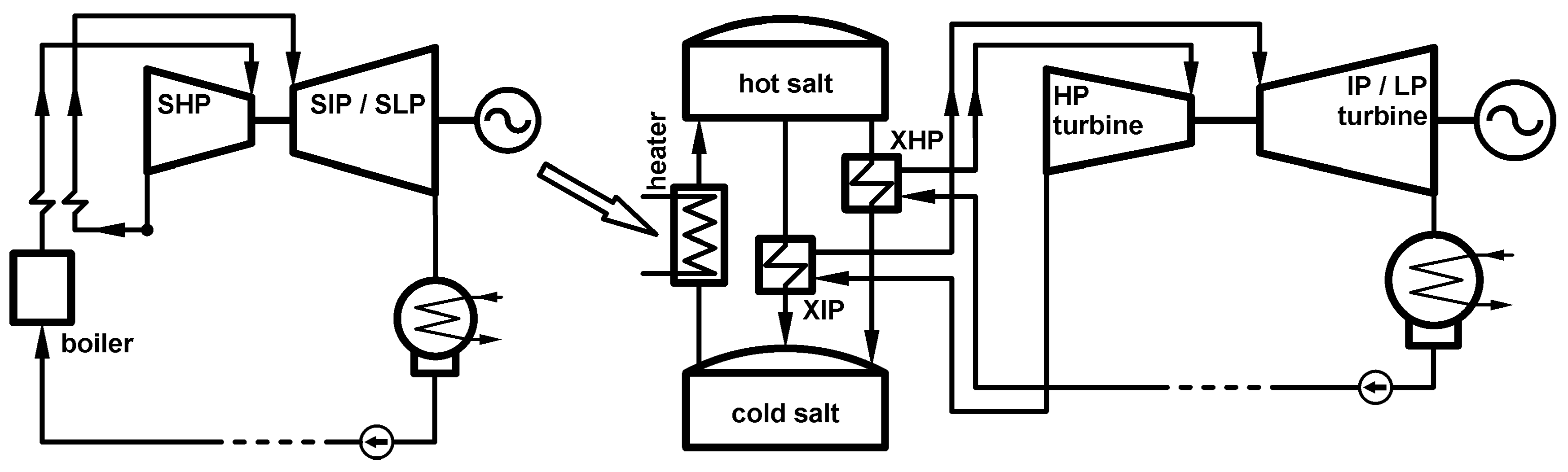
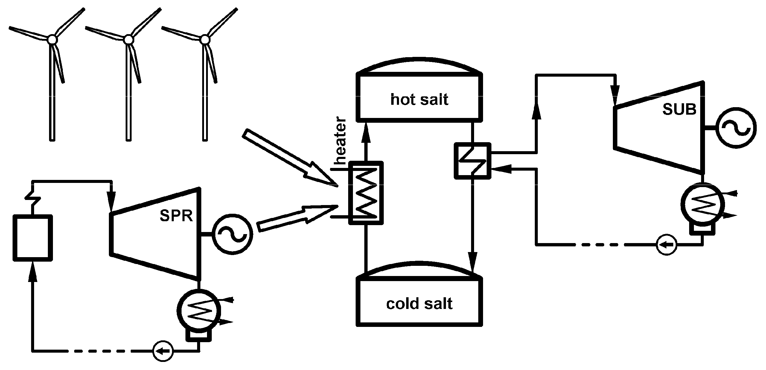
The combined cycle and the energy storage installations are shown in Figure 1. The steam turbines in the figure are simplified and shown as high pressure and intermediate and low pressure sections only. The regeneration heat exchangers are omitted. The cycle includes the supercritical turbine (SHP and SIP/SLP) with the steam boiler and the subcritical turbine (HP and IP/LP) without a boiler. The cycles are connected through the molten salt energy storage with hot and cold tanks.
The supercritical steam turbine operates as a foundation of a power grid. It compensates the fluctuations of the electric power generated by the renewables. For a single turbine it causes continuous fluctuations of the load.
In the technical solution shown in Figure 1 the supercritical turbine always operates under the full load even if the share of the energy from the renewables in the power grid temporarily increases. This is the first option of the modernization. The excess power generated in the supercritical turbine is used in the electric heater to increase the temperature of the molten salt. The excess energy is then stored in the hot tank with the molten salt. Later, when the share of the energy generation from the renewables decreases, the stored energy is used to generate the life and the reheat steam for the subcritical turbine. The subcritical turbine operates without a steam boiler, so its only source of the steam is the steam generator powered by the energy storage system.
The main advantage of the combined cycle is the possibility to supply the electric power to the grid even below the level that is defined as a minimum for the supercritical turbine, while the turbine operates under its nominal conditions. Both the supercritical boiler and the supercritical turbine always operate under a full load independent of the power demand. From a global perspective this allows one to decrease the total number of fossil-fueled units that constitute the foundation of the power grid. The steam generator for the subcritical turbine allows a very fast start-up because the boiler start-up is avoided since there is no boiler. If the methods for a rapid start-up are applied then the whole cycle becomes very flexible.
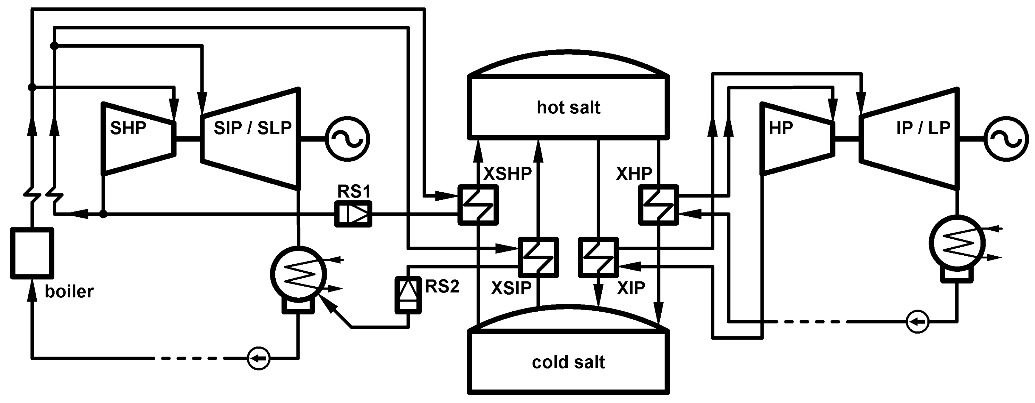
A similar concept is shown in Figure 2. The loading process of the energy storage is different. In the first option the excess power was used to load the energy storage, here it is the excess steam that is the source of the heat to increase the molten salt temperature.
The supercritical steam turbine is connected to the energy storage system through two heat exchangers. The first one (XSHP) is fed with the life steam and the second one (XSIP) with the reheated steam from the supercritical steam boiler. The fossil-fueled boiler operates under a full load and generates the nominal amounts of live and reheated steam. The turbine generates power at a level equal to the current demand from the grid. The flow rates of the live and the reheated steam to the turbine correspond to the current demand. The excess steam flows to the steam−salt heat exchangers. These exchangers are located at the by-pass systems of the high-pressure turbine and the intermediate and low pressure turbines. They are the parts of the steam pressure and temperature reduction stations. The excess life steam flows to the high-pressure steam-salt exchanger (XSHP in Figure 2) and then to the pressure and temperature reduction station RS1. The steam parameters are matched to the parameters of the steam at the outlet of the high-pressure turbine. The excess steam mixes with the steam at the outlet of the HP turbine and is returned to the boiler for reheating The excess reheat steam flows to the exchanger marked as XSIP in Figure 2 and then to the station RS2.
The temperature of the steam for the supercritical turbine is sufficient to generate the steam at the nominal temperature required for the subcritical turbine later on. The steam generation for the subcritical turbine is the same as in the first modernization option shown in Figure 1.
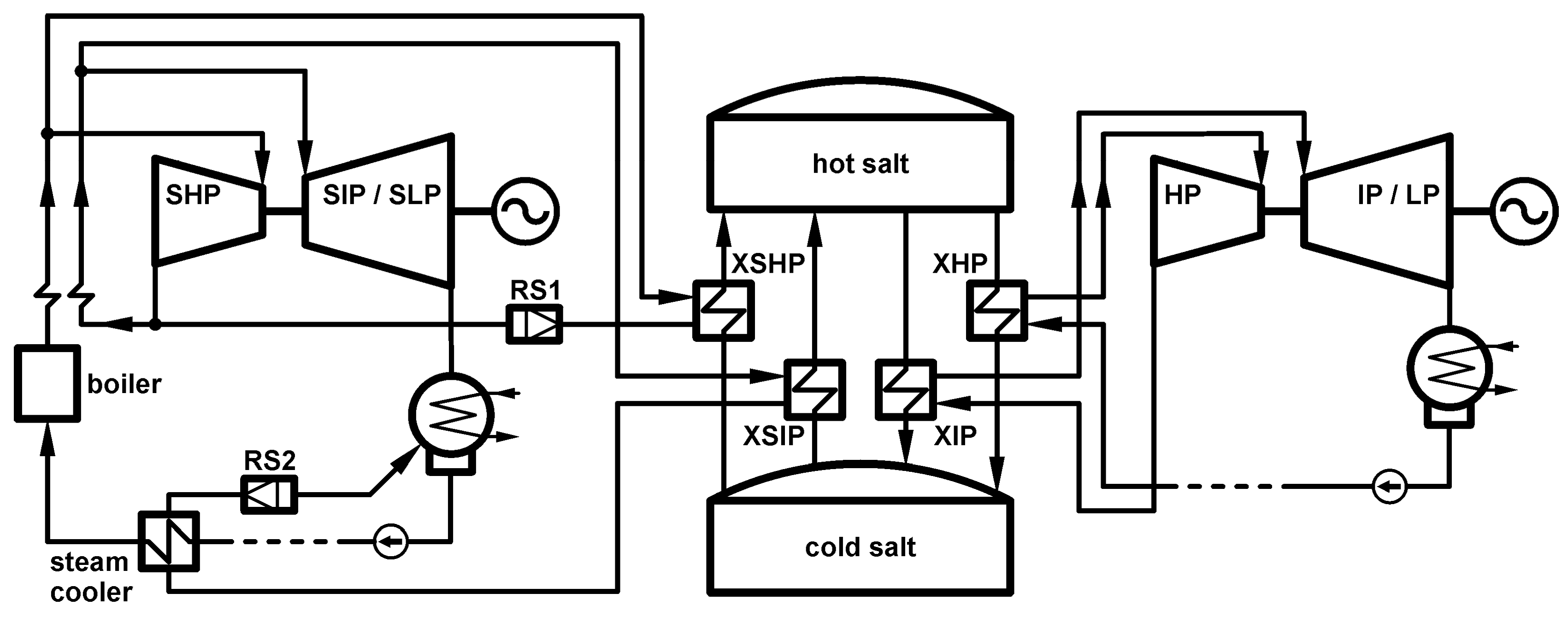
The third option is a modification of the second one. The supercritical cycle now has an additional steam cooler that increases the temperature of the feed water, which flows to the boiler. This modification is shown in Figure 3. The new steam cooler is located between the intermediate pressure steam-salt exchanger and the station RS2. The modification is possible due to the relatively high temperature of the steam at the outlet of the intermediate pressure steam-salt exchanger. The recovery of the heat from the steam improves the cycle efficiency.
The unmodified cycle of the supercritical steam turbine already includes a steam cooler for the steam flowing from a steam extraction in a turbine to a feed water heater. However, during an off-design operation period the feed water temperature remains much lower than under full load operation and therefore the addition of a new steam cooler is thermodynamically satisfied.
3. Numerical Models of the Turbines
The analysis of the cycles modernized according to the suggestions given above involved numerical simulations. A quasi one-dimensional model was prepared for the simulations at different levels of the load [19]. The models were developed on the basis of measurement data from real turbines. The data allowed us to determine the performance maps for the machines that make up the steam cycle.
Apart from the performance maps the numerical model includes the mass and the energy equations for each machine or device that is a part of the steam cycle. In particular the model includes the equation of the turbine capacity that relates the pressure distribution along the steam path, the steam temperature and the flow rate. For a group of turbine stages this relation may be described as:
Two functions heavily influence the operation of the supercritical steam turbine. The first one is related to the life steam pressure. For a stand-alone turbine the pressure depends on the mass flow rate of the life steam generated in the boiler:
In the modernization options 2 and 3 the flow of the steam generated in the boiler is different than the flow to the turbines. Due to this reason the life steam pressure is related to the flow of the steam to the turbine:
The Equations (2) and (3) include the same function f but a different flow. If not stated otherwise the proceeding simulation results were obtained for Equation (2).
The second important function is related to the temperature of the reheated steam. This value also depends on the load. For a low load the supercritical boiler generates the reheated steam at a temperature that is lower than the design value due to the small mass flow rate of the flue gas. Therefore:
The reheated steam temperature depends solely on the steam flow in the boiler, so for the modernization options analyzed here this is always constant, since the flow of the steam in the boiler is always equal to the nominal (design) value.
The assessment of the modernization bases on the efficiency of the power generation. A current efficiency may be calculated as a ratio of the electric power to the heat delivered to the steam cycle in the boiler:
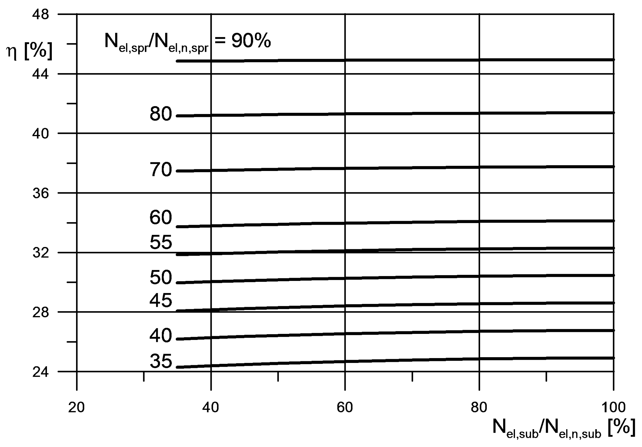
Figure 4 presents the power generation efficiencies for the supercritical and the subcritical turbines working separately before the modernization and each with its own boiler. The efficiencies are marked as “spr” and “sub” respectively in the Figure 4. They are shown in the relation to the load.
The graphs from the Figure 4 are extrapolated in the range of the low load. The minimal load for the supercritical turbine is 40% and for the subcritical one 55%. Under the lower loads the boilers are not able to sustain the required temperature of the steam. The extrapolation was prepared under the assumption that the boilers uphold the temperature required by Equation (3). This is done in order to prepare a reference basis for the comparison of the modernization options.
The current efficiency of the power generation is not a proper definition for systems with an energy storage. Since Equation (5) involves the current values it does not include any information about the heat delivered earlier to the energy storage. Therefore, the options of the modernization suggested here are compared through the power generation efficiency defined as:
The first term in the numerator of the fraction in the above equation is the energy produced by the supercritical turbine during the loading of the energy storage and the second term is the energy produced by the subcritical turbine during an unloading process that completely drains the stored energy. The efficiency is calculated for a chosen period of the operation. In the analysis this period was defined in the following way. The energy storage is loaded up to the level that allows the subcritical turbine to operate for 24 h without any other energy source. Thus, the period for which the efficiency is calculated is the period of the energy loading plus the 24 h of the energy unloading. The energy delivered to the system that appears in the denominator of the fraction in Equation (6) is the energy delivered to the steam cycle in the supercritical boiler during the loading process. The equation does not include the energy produced in the supercritical turbine during the unloading process because it requires additional energy delivered to the steam cycle. The current values of the power and the heat delivered to the steam cycle may be inserted into Equation (6), which then becomes:
The numerical simulations include the decrease of the salt temperature in the hot tank due to the imperfect insulation. The hot tank is loaded with the molten salt at the temperature that is 5 degrees Kelvin higher than the temperature of the salt later used to generate the steam for the subcritical turbine.
4. Methodology
The numerical model described in the preceding section allows one to simulate the performance of the investigated power plant in the chosen cases of the modernization. The simulations were conducted for a rather wide range of loads from 35% to 100% for the subcritical steam turbine and 35% to 90% for the supercritical steam turbine. Since the design power outputs are different for both turbines the load percentages translate into different values in megawatts. A number of combinations of the loads were analyzed.
During a typical operation the power demand undergoes continuous fluctuations and the turbine output must match the demand. In order to compare different options of the modernization one may chose two approaches. The first one is to assume a particular curve of the demand over time and conduct the simulations for that curve matching it with the turbine load. However, the shape of the demand curve strongly depends on the location of the power plant and local conditions of the operation (cooling possibilities, ambient conditions etc.). For that reason a second approach was applied. It was assumed that the energy storage loading and unloading is conducted under a constant power supply to the grid. The power supply may be different for the loading and the unloading but remains constant during both processes.
Each run of the simulation model started with the given values of the power delivered to the grid from the supercritical and the subcritical turbine. The subcritical turbine always matches its power output to the power demand from the grid. The supercritical turbine matches the power demand in the options 2 and 3 of the modernization but in the option 1 it operates always at 100% delivering the excess power to the electric heater that increases the temperature of the molten salt.
The simulation model then matched the turbines performance to the selected levels of the power demand. The model calculated the required flow rates and the parameters of steam in the characteristic locations of the power plant (inlets and outlets of the turbine sections and heat exchangers, etc.). Based on the parameters in the steam cycles the flow rates of the molten salt were calculated and then the time required for the energy loading and the unloading processes. Finally the efficiency of the electric energy generation could be determined.
The numerical simulations were conducted for a constant value of the energy delivered to the steam cycle in the supercritical boiler. This constant value is equal to the value for the full load operation of the supercritical steam cycle. The algorithm that drove the calculations and assured the convergence of the numerical model for the options 2 and 3 had to match the two main flows. The flow of the life steam at the inlet to the supercritical turbine had to match the given power demand from the supercritical turbine and the flow of the steam generated in the supercritical boiler had to match the constant value of the energy delivered to the steam cycle in the boiler.
The modeling results are presented in the next section of the paper in the form of the graphs that present the efficiency and the loading time for different combinations of the power demand from the analyzed turbines.
5. Modernization Effects
5.1. Option 1
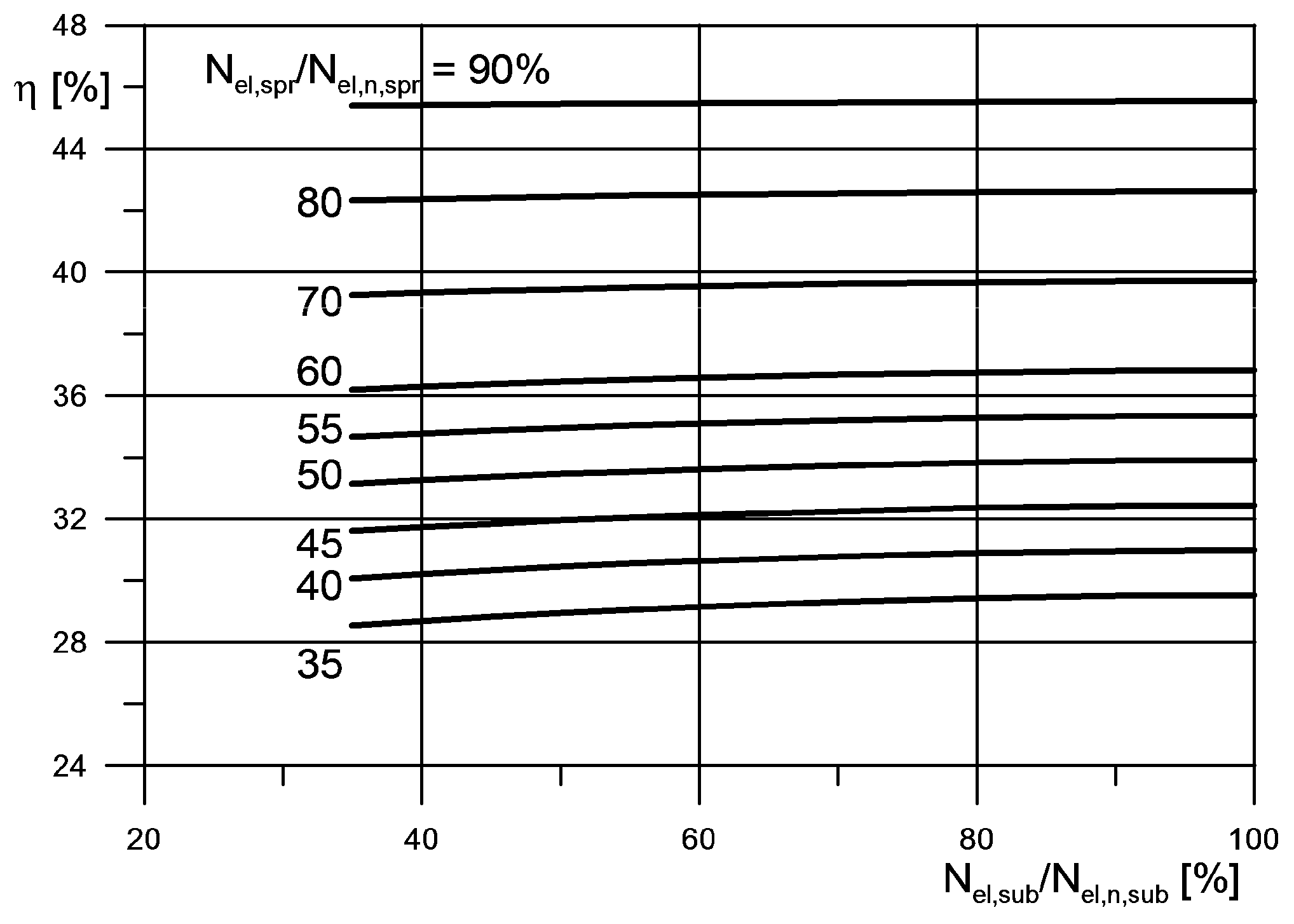
The addition of the energy storage system to the steam cycles generally lowers the power generation efficiency. This decrease is shown in Figure 5 for the first option of the modernization. The graph in the figure presents the values calculated from Equation (6) for different levels of the electric power supply/demand. The power supplied to the grid from the supercritical turbine Nel,spr refers to the loading process. This is a relative value in Figure 5 and its reference value is the nominal (design) power output of the supercritical turbine Nel,n,spr. According to the assumptions for the option 1 the supercritical turbine operates under the full load independent of the current power demand and the excess power is used for the loading of the energy storage.
The power demand for the subcritical turbine Nel,sub is given for the unloading process. The subcritical turbine power is always equal to the power supplied to the grid. Its value in Figure 5 is relative and its reference value is the nominal (design) power output of the subcritical turbine Nel,n,sub.
The graph shows that the efficiency depends mostly on the level of the power demand during the loading process. This is due to the difference of the nominal power between the two turbines—the nominal power of the supercritical turbine is over two times larger than the power of the subcritical turbine. The values in Figure 5 should be compared to the values in Figure 4. The current efficiencies of the supercritical and subcritical turbines for a full load operation are 48.4% and 42.0%, respectively.
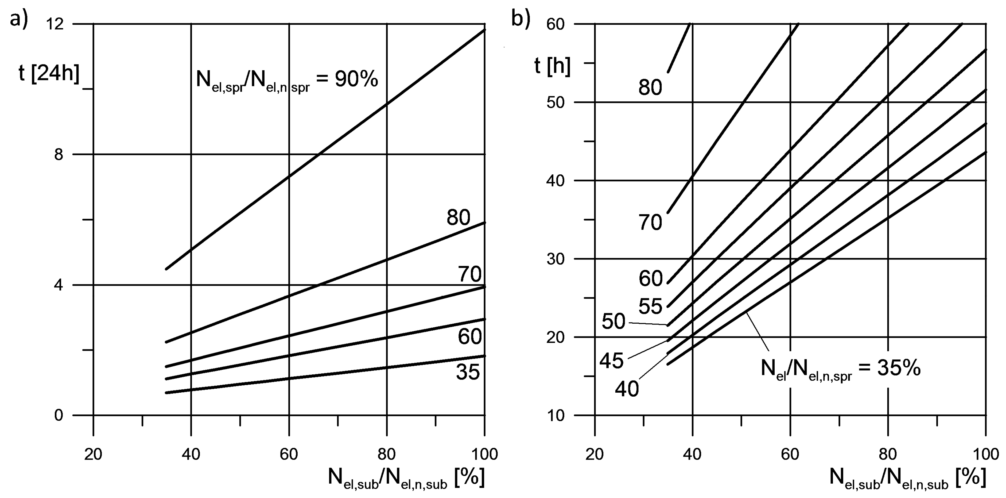
An important piece of information in the evaluation of the combined cycle is the time required to load the energy storage system. Figure 6 presents the dependency between the time of the loading process and the power demands during the two processes: the loading and the unloading. According to the assumptions described in the preceding sections this time is always determined for the amount of energy that allows the subcritical turbine to operate for 24 h during the given load. Of course the amount of the stored energy is different for different loads. The graph is divided into two sections with different ranges on the vertical axes due to the large density of the lines.
The low power demand during the loading process results in more excess power supplied to the electric heater to increase the temperature of the molten salt and to store the energy. The time required to load the storage is then shorter. If the power demand from the supercritical turbine is under 50 percent of the nominal turbine power then the loading period is around two days.
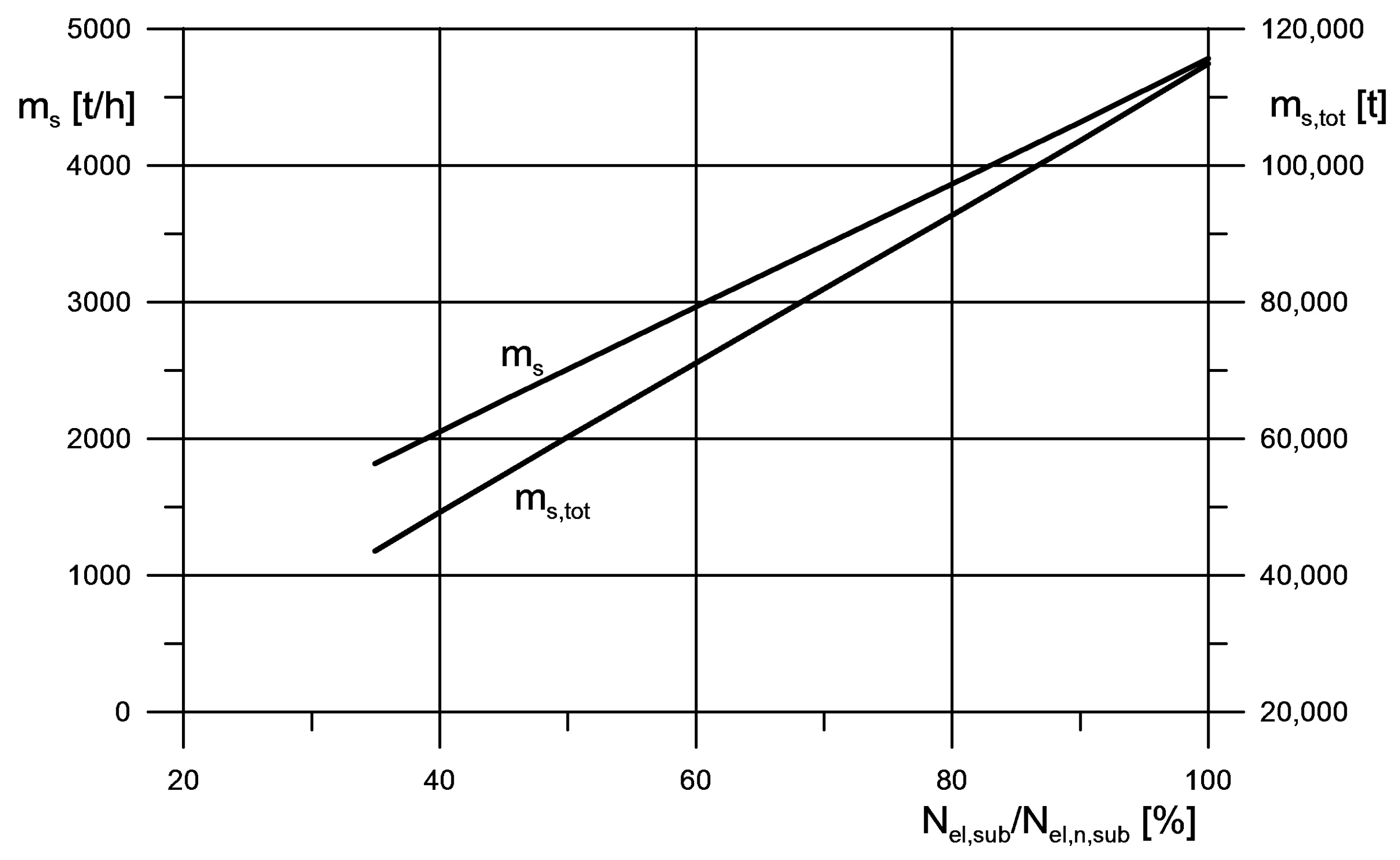
The values of the molten salt flow rate and the total required amount of the molten salt in the hot tank are shown in Figure 7. Both values are shown in relation to the subcritical turbine load.
The design of the tanks, the electric heater and the steam-salt heat exchangers must match the largest values shown in the Figure 7. The design is a separate subject not discussed in this paper.
It should be noted that due to the difference in the nominal power outputs between the turbines the unloading will probably be conducted under the higher load then the power demand during the loading process.
5.2. Option 2
In the modernization options 2 and 3 the power output of the supercritical turbine during the energy storage loading always matches the current demand from the power grid. However, the amount of the heat supplied to the steam cycle in the boiler is always equal to its nominal value. The excess steam flows to the steam—salt exchangers and increases the temperature of the salt to store the energy.
The power generation efficiency for the energy storage loading and the unloading are shown in Figure 8 for option 2. Compared to option 1 this technical solution has lower efficiency, especially for the lower power demands. the change is the result of different type of the energy conversion. In option 1 the temperature of the molten salt is due to the electric power, while in option 2 it is due to the heat carried in the hot steam.
The loading time of the energy storage required for the 24 h operation of the subcritical turbine is longer than in option 1. The length of the loading period is shown in Figure 9. The graph is again divided into two sections with different ranges on the vertical axes due to the density of the lines. The difference between options 1 and 2 is around 10 h with option 1 providing the shorter period. The total amount of the molten salt required to guarantee the 24 h operation of the subcritical turbine and the flow rate of the salt is the same as in option 1.
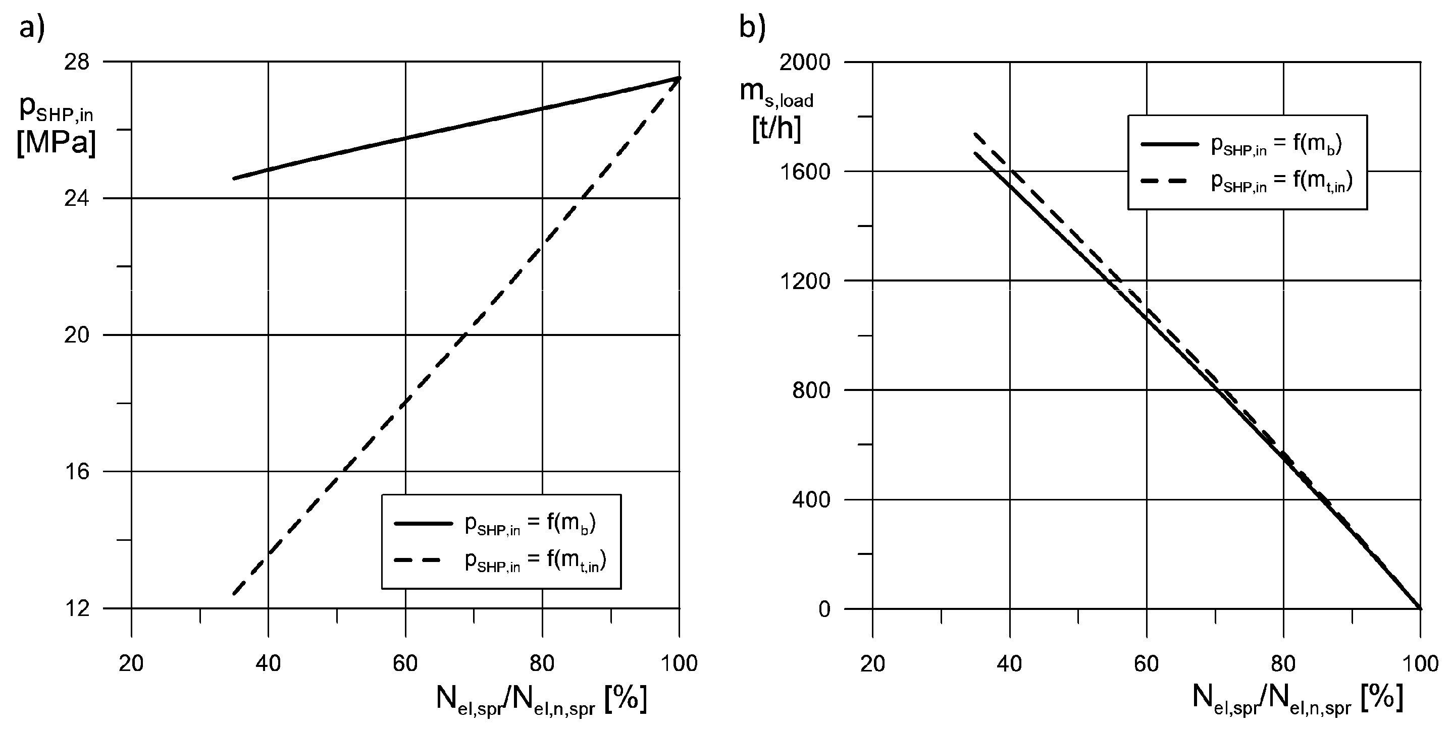
The results described so far for option 2 are from the simulations where the life steam pressure at the inlet to the supercritical turbine depends on the steam flow in the boiler according to Equation (2). The results are different if the pressure is adjusted to the load according to Equation (3). The values of the pressure for both Equations (2) and (3) are shown in Figure 10a. The line for Equation (2) is not horizontal in the figure because the constant value in the calculations was the amount of energy delivered to the steam cycle in the boiler and not the steam flow.
According to Figure 10b the cycle with the lower pressure of the life steam delivers more molten salt to the hot tank while the amount of energy delivered to the steam cycle in the supercritical boiler is the same. The larger flow of the molten salt results in a shorter period of the loading of the energy storage. Figure 11 compares the chosen cases of the loading process for different levels of the power demand during the loading, different load during the unloading and two types of the function that determines the life steam pressure (Equations (1) or (2)).
The efficiency of the power generation for the whole combined cycle also increases. The comparison of the efficiency values is presented in Figure 12. The figure includes the results of the simulations for the low levels of the loads. The differences between the two types of the adjustment of the life steam pressure are smaller for the operation that is close to the full load because the steam that flows to the turbine is almost equal to the total flow of the steam generated in the boiler and both pressure adjustment Equations (1) and (2) give similar results.
The adjustment of the life steam pressure and its lower values for the part-load operation generally lead to the improvement of the power generation efficiency. In the combined cycle with the energy storage system presented here this improvement is visible for the whole cycle.
A larger improvement of the power generation efficiency may be achieved through the decrease of the life and the reheat steam temperature for the subcritical turbine. Of course, this leads to a decrease of the current efficiency of the subcritical turbine but it improves the efficiency of the whole combined system. Lower temperature of the steam generated for the subcritical turbine requires a lower temperature of the molten salt in the hot tank. This allows one to increase the flow rate of the molten salt in the steam-salt exchangers while keeping constant the amount of energy delivered to the supercritical cycle. The flow rate of the salt is compared in Figure 13 for two different values of the temperature of the steam for the subcritical turbine.
A larger flow rate results in a shorter loading period and this leads to a better efficiency of the power generation of the whole cycle with the energy storage. The values of the efficiency are compared in Figure 14a. The improvement of the efficiency in the reference to the nominal values of the steam temperature for the subcritical turbine is around 0.5 percentage points.
The shortened time of the loading process is shown in Figure 14b. The hot tank is filled faster when the subcritical steam temperature is lower. The comparison to the results with the nominal temperature value shows that the loading process is 2–3 h shorter, depending on the load. This is especially important for the low loads because the 2–3 h are 10% of the total loading time.
The results in Figure 13 and Figure 14 were obtained in the simulations under the assumption that the values of the life and the reheat steam temperature are equal. The values of 535 and 515 °C are respectively the nominal value and the minimal value that may be applied without the increased erosion process in the low-pressure part of the subcritical turbine.
5.3. Option 3
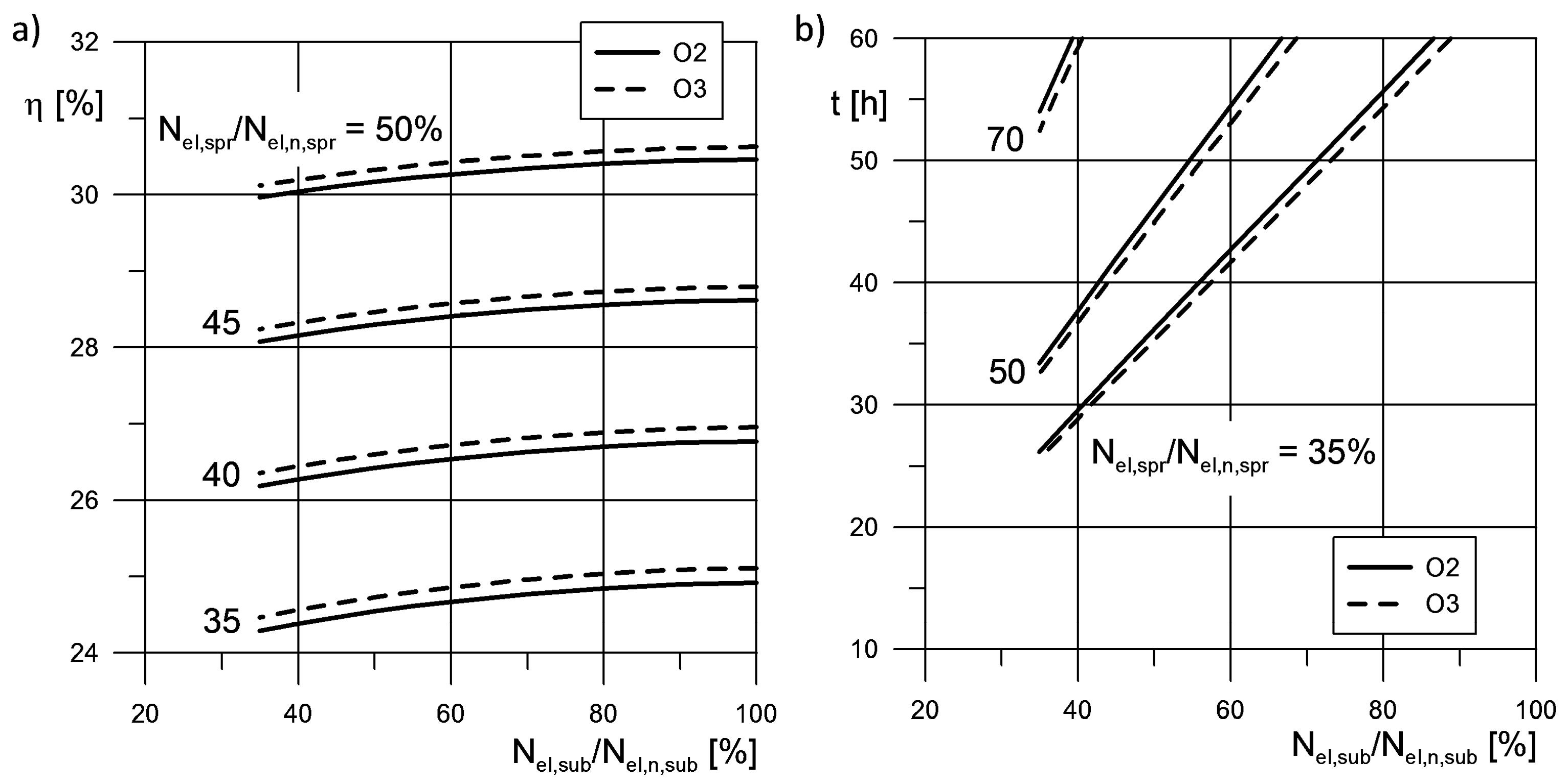
The steam temperature at the outlet of the intermediate steam-salt exchanger (XSIP in Figure 2 or Figure 3) is relatively high. Its value is well above the saturation temperature. For this reason option 3 was investigated. In this option the heat in the steam at the outlet of the exchanger is used to increase the temperature of the feed water that flows to the supercritical boiler (Figure 3). A new steam cooler is installed downstream of the boiler. The results of the simulation including the power generation efficiency and the time of the loading process for the energy storage for this option are gathered in Figure 15.
The addition of the new steam cooler increases the power generation efficiency and decreases the loading period. However, the results of the simulations prove that the profit in terms of the efficiency and time is small. The investment costs of the new steam cooler would probably not be justified in an economical analysis.
It should be emphasized here that the variants of option 2 described earlier did not include the new steam cooler but involved the adjustments of the supercritical steam pressure or the subcritical steam temperature. These adjustments do not require additional investment cost but the change of the parameters of the working fluid in the already existing machines.
5.4. Direct Integration with Renewables
All the technical solutions presented here are meant for the foundation of a power system. Again it should be recalled that the main task of the foundation is the compensation of the fluctuations of the power generated in the renewable energy sources. According to the assumptions given in the Introduction the source of the energy for the foundation is fossil fuel.
The structure of the presented power plant with a storage system allows one to use renewable energy sources (RES) in the foundation. This may be done through the connection of the renewables not directly to the power grid but rather to the energy storage system in the cycles presented here. This idea is depicted in Figure 16.
The thermodynamic cycle from Figure 16 is a modified version of option 1 from Figure 1. The difference is in the renewable source that is connected to the energy storage installation. The electric power from wind, sun or another is used to increase the temperature of the molten salt in the electric heater. The electric power from the RES is stored only if its level exceeds the current demand in the grid. This solution is similar to the solutions in the countries with sufficient solar irradiance or the strength of the wind, where the renewables feed the energy storage. In the countries with worse conditions for the extraction of the energy from the renewables the presence of the supercritical turbine guarantees the continuity of the power supply to the grid.
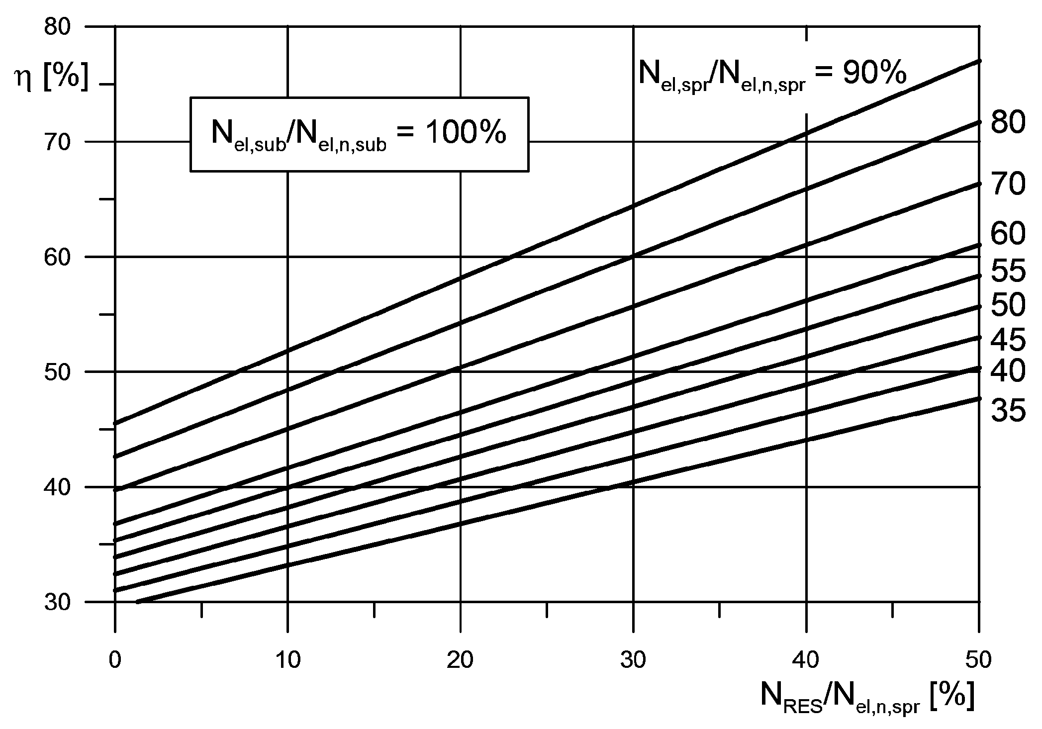
The results of the simulations for the cycle integrated with the renewables are shown in Figure 17 and Figure 18. They were conducted without defining the particular type of the renewable energy source. Figure 17 presents the efficiency of the power generation for different shares of the power from the renewables. In order to compare this case with the previous cases the simulations were conducted for constant levels of the power from the renewables. The efficiency is defined as:
In the above equation the share of the power from the renewables is relative to the nominal power of the supercritical turbine. The values of the efficiency from Figure 17 are high because the power from the renewables is treated here as an effect that does not require an input in the form of a delivered energy. The graph in Figure 17 was obtained for a simulation with the full load operation of the subcritical turbine, so Nel,sub/Nel,n,sub is 100%.
The integration of the steam turbines and the renewables significantly shortens the loading time of the energy storage. A comparison of loading times is shown in Figure 18.
It should be emphasized that a constant power supply from the renewables during the loading was assumed in order to compare the options and variants of the thermal cycles analyzed in the study. In practice the renewable sources, especially the wind, exhibit significant fluctuations of a current power.
5.5. Comparison
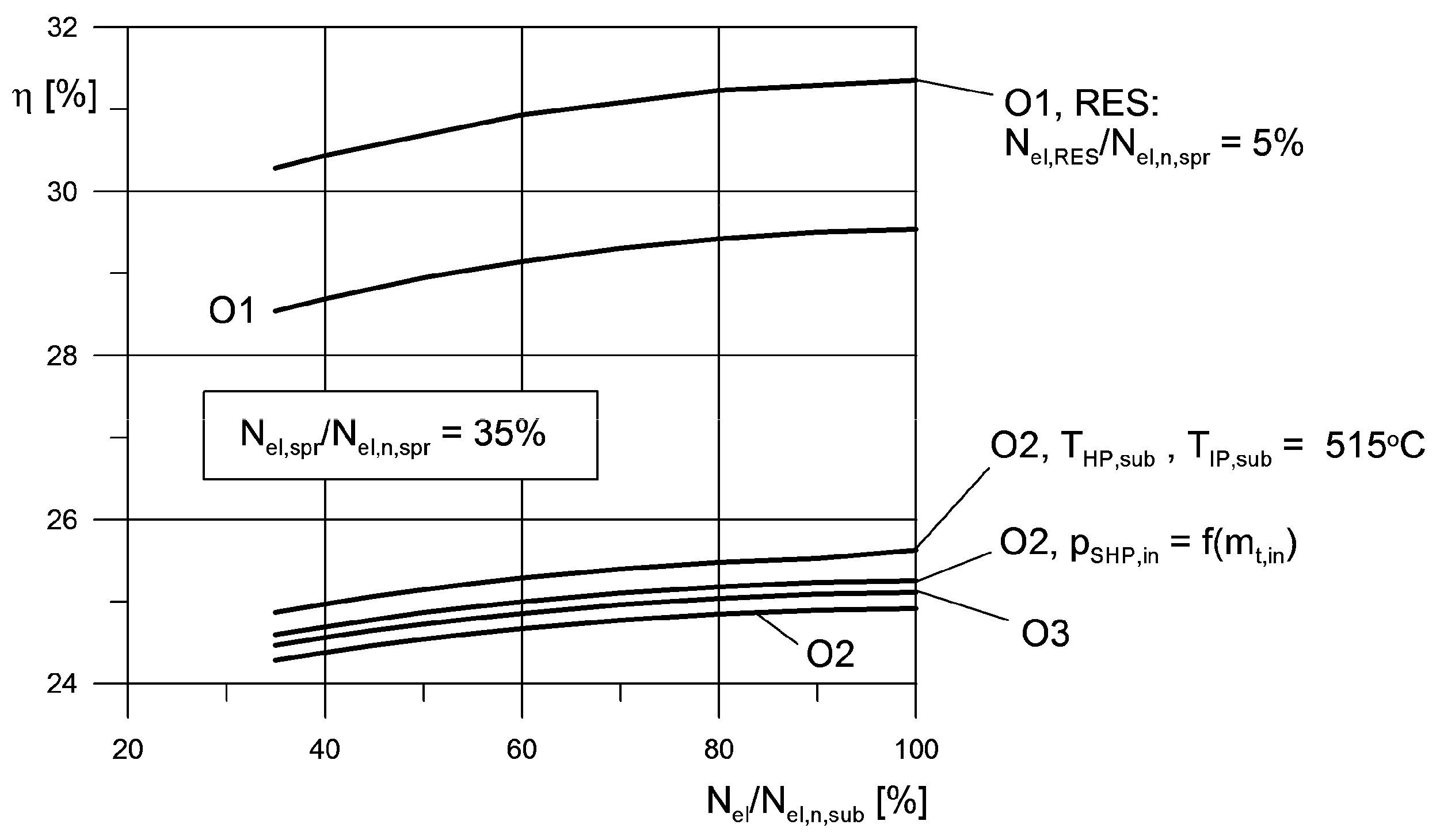
The results of the simulations for different cases are compared in Figure 19. The figure presents the power generation efficiency for the energy storage loading with the power supply from the supercritical turbine of 35%. The following options are compared:
- O1, O2 and O3—options 1, 2 and 3, respectively,
- O2, pSHP,in = f(mt,in)—option 2, supercritical steam pressure adjusted according to Equation (3),
- O2, THP,sub, TIP,sub = 515 °C,
- O1, RES—option 1 integrated with RES, the power supplied from the RES is 5% of the nominal supercritical steam turbine power.
The comparison of the options shows that the option 1 always provides the largest efficiency of the power generation. The conversion of the electric power into the heat stored in the molten salt is more efficient than the conversion of the heat in the hot steam. The efficiency may be improved if the steam parameters are adjusted. This applies to the steam parameters in the supercritical and the subcritical turbine.
Option 3 that is a variant of option 2 with an additional steam cooler provides an efficiency gain but it is smaller than the gain from the adjustment of the steam parameters. Of course the adjustment should also be made for option 3. However the cost of the additional steam cooler may not justify the upgrade. It should be noted that the adjustment of the steam parameters is done without any investment cost.
6. Conclusions
The application of the energy storage system as a buffer between a supercritical and a subcritical turbine allows one to create a unit that generates power over a very wide range of loads. A unit of this type may be an important part of a power system with a large number of the renewable energy sources. The wide range of the loads allows one to decrease the total number of similar units that are required in the system foundation. It also makes the unit less dependent on the ambient conditions.
The presented solutions are designed for power grids that undergo a transformation from fossil fuels to green energy. The solution involves the machines from existing systems that are still operational. Their harmful impact on the natural environment is reduced due to the integration with newer technologies.
Among the options presented here the option that allows to use the renewable energy sources in the power plant that is a foundation of a power grid showed the best efficiency. However, this was obtained in the simulations under the assumption that the energy supplied from the RES is constant, which is hardly true. The integration of the RES with a core power plant should be carefully analyzed for a particular location and local conditions regarding the availability of the renewables.
The difference between the options presented here is the type of the energy conversion during the loading process. Option 1 with the electric energy supplied to the heater that increases the temperature of the molten salt performed better in the simulations in terms of the power generation efficiency. Option 2 with the heat in the steam converted to the heat in the molten salt had lower efficiency even with the adjusted parameters of the steam. Option 3 is just a minor improvement when compared to option 2.
In all the options the supercritical steam boiler always operates with the highest possible efficiency. This translates to the lowest possible emissions per a unit of the produced electric power. The energy storage system with the molten salt that was analyzed here is very often applied to solar power plants. The salt is pushed through vertical solar tower in a number of tubes exposed to the sun. The flow must be divided into a considerable large number of pipes due to the exposure to the sunlight. The salt heater in the cycles described here is free from this restriction.
Author Contributions
Conceptualization, W.K. and A.R.; methodology, W.K. and A.R.; software, W.K.; validation, A.R.; investigation, W.K. and A.R.; data curation, W.K.; writing—original draft preparation, W.K.; writing—review and editing, A.R.; All authors have read and agreed to the published version of the manuscript.
Funding
This research received no external funding.
Acknowledgments
The research was supported by research funds of the Silesian University of Technology, Gliwice, Poland.
Conflicts of Interest
The authors declare no conflict of interest.
Nomenclature
| HP | high pressure subcritical steam turbine |
| IP | intermediate pressure subcritical steam turbine |
| LP | low pressure subcritical steam turbine |
| m | mass flow rate [kg/s] |
| Nel | electric power [MW] |
| p | pressure [MPa] |
| Qd | heat delivered to a cycle [MW] |
| SHP | high pressure supercritical steam turbine |
| SIP | intermediate pressure supercritical steam turbine |
| SLP | low pressure supercritical steam turbine |
| T | temperature [°C] |
| XHP | high pressure heat exchanger, subcritical steam section |
| XIP | intermediate pressure heat exchanger, subcritical steam section |
| XSHP | high pressure heat exchanger, supercritical steam section |
| XSIP | intermediate pressure heat exchanger, supercritical steam section |
| η | power generation efficiency [%] |
| Subscripts | |
| b | boiler |
| in | inlet |
| out | outlet |
| n | nominal, design |
| RES | renewable energy source |
| spr | supercritical |
| sub | subcritical |
| t | turbine |
References
- Rusin, A.; Wojaczek, A. Trends of changes in the power generation system structure and their impact on the system reliability. Energy 2015, 92, 128–134. [Google Scholar] [CrossRef]
- Sarbu, I.; Sebarchievici, C. A comprehensive review of thermal energy storage. Sustainability 2018, 10, 191. [Google Scholar] [CrossRef] [Green Version]
- Shi, N.; Luo, Y. Energy storage system sizing based on a reliability assessment of power systems integrated with wind power. Sustainability 2017, 9, 395. [Google Scholar] [CrossRef] [Green Version]
- Urbanucci, L.; D’Ettorre, F.; Testi, D. A comprehensive methodology for the integrated optimal sizing and operation of cogeneration systems with thermal energy storage. Energies 2019, 12, 875. [Google Scholar] [CrossRef] [Green Version]
- Li, W.; Li, T.; Wang, H.; Dong, J.; Li, Y.; Cui, D.; Ge, W.; Yang, J.; Okoye, M.O. Optimal dispatch model considering environmental cost based on combined heat and power with thermal energy storage and demand response. Energies 2019, 12, 817. [Google Scholar] [CrossRef] [Green Version]
- Zsembinszki, G.; Orozco, C.; Gasia, J.; Barz, T.; Emhofer, J.; Cabeza, L.F. Evaluation of the State of Charge of a Solid/Liquid Phase Change Material in a Thermal Energy Storage Tank. Energies 2020, 13, 1425. [Google Scholar] [CrossRef] [Green Version]
- Bartela, Ł. A hybrid energy storage system using compressed air and hydrogen as the energy carrier. Energy 2020, 196, 117088. [Google Scholar] [CrossRef]
- Zhang, X.; Wu, Y.; Ma, C.; Meng, Q.; Hu, X.; Yang, C. Experimental study on temperature distribution and heat losses of a molten salt heat storage tank. Energies 2019, 12, 1943. [Google Scholar] [CrossRef] [Green Version]
- Herrmann, U.; Kelly, B.; Price, H. Two-tank molten storage for parabolic trough solar power plants. Energy 2004, 29, 883–893. [Google Scholar] [CrossRef]
- Das, A.K.; Inigo, P.; Terdalkar, R.J.; Joshi, A.; Wang, C.; Clark, M.M.; McGrane, D.; Deng, L. Design features and control concepts of ALSTOM molten salt receiver. Energy Procedia 2015, 69, 350–359. [Google Scholar] [CrossRef] [Green Version]
- Kelly, B.; Kearny, D. Thermal Storage Commercial Plant Design Study for a 2-Tank Indirect Molten Salt System; USA National Renewable Energy: Golden, CO, USA, 2006. [Google Scholar]
- Li, C.; Yang, Z.; Zhai, R.; Yang, Y.; Patchigolla, K.; Oakey, J.E. Off-design thermodynamic performances of a solar tower aided coal-fired power plant for different solar multiples with thermal energy storage. Energy 2018, 163, 956–968. [Google Scholar] [CrossRef]
- Garbrecht, O.; Bieber, M.; Kneer, R. Increasing fossil power plant flexibility by integrating molten-salt thermal storage. Energy 2017, 118, 876–883. [Google Scholar] [CrossRef]
- Guo, J.-Q.; Li, M.-J.; Xu, J.-L.; Yan, J.-J.; Wang, K. Thermodynamic performance analysis of different supercritical Brayton cycles using CO2-based binary mixtures in the molten salt solar power tower systems. Energy 2019, 173, 785–798. [Google Scholar] [CrossRef]
- Pacheco, J.E.; Wolf, T.; Muley, N. Incorporating Supercritical Steam Turbines into Advanced Molten-Salt Power Tower Plants Feasibility and Performance; Sandia National Laboratories: Livermore, CA, USA, 2013. [Google Scholar]
- Gonzalez, P.A.; Gomez-Hernandez, J.; Briongos, J.V.; Santana, D. Thermo-economic optimization of molten salt steam generators. Energy Convers. Manag. 2017, 8, 228–243. [Google Scholar] [CrossRef]
- Reyes-Belmonte, M.A.; Sebastián, A.; Gonzalez-Aguilar, J.; Romero, M. Performance comparison of different thermodynamic cycles for an innovative central receiver solar power plant. J. Phys. Chem. Ref. Data 2017, 1850, 160024. [Google Scholar] [CrossRef] [Green Version]
- Serrano-Lopez, R.; Fradera, J.; Cuesta-Lopez, S. Molten salts database for energy applications. Chem. Eng. Process. Process Intensif. 2013, 73, 87–102. [Google Scholar] [CrossRef] [Green Version]
- Chmielniak, T.; Kosman, W.; Kosman, G. Simulation Modules of Thermal Processes for Performance Control of Combined Heat and Power Plant with a Gas Turbine Unit. Appl. Therm. Eng. 2007, 27, 2181–2187. [Google Scholar] [CrossRef]
Figure 1.
The loading of the energy storage installation with an electric heater.

Figure 2.
Energy storage loading with the heat from the life and the reheat steam.

Figure 3.
Energy storage loading with the heat from the excess steam with an additional steam cooler.
Figure 3.
Energy storage loading with the heat from the excess steam with an additional steam cooler.

Figure 4.
Current efficiencies of the power generation for the analyzed turbines.

Figure 5.
Power generation efficiency—option 1.

Figure 6.
Loading time of the energy storage for the 24 h of the subcritical turbine operation—option 1—full graph (a) and its enlarged section (b).
Figure 6.
Loading time of the energy storage for the 24 h of the subcritical turbine operation—option 1—full graph (a) and its enlarged section (b).

Figure 7.
Molten salt flow rate and total amount for the 24 h of subcritical turbine operation—option 1.
Figure 7.
Molten salt flow rate and total amount for the 24 h of subcritical turbine operation—option 1.

Figure 8.
Power generation efficiency—option 2.

Figure 9.
Loading time of the energy storage for the 24 h of the subcritical turbine operation—option 2—full graph (a) and its enlarged section (b).
Figure 9.
Loading time of the energy storage for the 24 h of the subcritical turbine operation—option 2—full graph (a) and its enlarged section (b).

Figure 10.
Life steam pressure (a) and the flow of the molten salt during the loading of the energy storage (b) for the option 2, steam pressure depends on the flow in the boiler pSHP,in = f(mb) or at the turbine inlet pSHP,in = f(mt).
Figure 10.
Life steam pressure (a) and the flow of the molten salt during the loading of the energy storage (b) for the option 2, steam pressure depends on the flow in the boiler pSHP,in = f(mb) or at the turbine inlet pSHP,in = f(mt).

Figure 11.
Loading time of the energy storage for 24 h of subcritical turbine operation—option 2, life steam pressure adjusted to the steam flow in the boiler or at the turbine inlet—full graph (a) and its enlarged section (b).
Figure 11.
Loading time of the energy storage for 24 h of subcritical turbine operation—option 2, life steam pressure adjusted to the steam flow in the boiler or at the turbine inlet—full graph (a) and its enlarged section (b).

Figure 12.
Power generation efficiency—option 2, life steam pressure adjusted to the steam flow in the boiler or at the turbine inlet.
Figure 12.
Power generation efficiency—option 2, life steam pressure adjusted to the steam flow in the boiler or at the turbine inlet.

Figure 13.
Flow rate of the salt during the loading process for different temperature of the steam for the subcritical turbine—option 2.
Figure 13.
Flow rate of the salt during the loading process for different temperature of the steam for the subcritical turbine—option 2.

Figure 14.
Power generation efficiency (a) and the loading time (b) for different life and reheat steam temperature for the subcritical turbine—option 2.
Figure 14.
Power generation efficiency (a) and the loading time (b) for different life and reheat steam temperature for the subcritical turbine—option 2.

Figure 15.
Power generation efficiency (a) and the loading time for 24 h of operation of the subcritical turbine (b)—options 2 and 3.
Figure 15.
Power generation efficiency (a) and the loading time for 24 h of operation of the subcritical turbine (b)—options 2 and 3.

Figure 16.
Cycle with a storage system for energy from the renewable sources and the supercritical turbine.
Figure 16.
Cycle with a storage system for energy from the renewable sources and the supercritical turbine.

Figure 17.
Power generation efficiency for different share of the power from the renewables—modernization according to the option 1.
Figure 17.
Power generation efficiency for different share of the power from the renewables—modernization according to the option 1.

Figure 18.
Loading time of the energy storage for 24 h of operation of the subcritical turbine with different share of the power from the renewables—option 1—full graph (a) and its enlarged section (b).
Figure 18.
Loading time of the energy storage for 24 h of operation of the subcritical turbine with different share of the power from the renewables—option 1—full graph (a) and its enlarged section (b).

Figure 19.
Power generation efficiency for the analyzed cases.


Table 1.
Comparison of the steam turbines under the investigation.
| Parameter | Unit | Supercritical Turbine | Subcritical Turbine |
|---|---|---|---|
| nominal power | MW | 460 | 217 |
| life steam temperature | °C | 560 | 535 |
| life steam pressure | MPa | 27 | 12.7 |
| life steam flow rate | t/h | 1300 | 668 |
| reheat steam temperature | °C | 580 | 535 |
© 2020 by the authors. Licensee MDPI, Basel, Switzerland. This article is an open access article distributed under the terms and conditions of the Creative Commons Attribution (CC BY) license (http://creativecommons.org/licenses/by/4.0/).
Share and Cite
MDPI and ACS Style
Kosman, W.; Rusin, A. The Application of Molten Salt Energy Storage to Advance the Transition from Coal to Green Energy Power Systems. Energies 2020, 13, 2222. https://0-doi-org.brum.beds.ac.uk/10.3390/en13092222
AMA Style
Kosman W, Rusin A. The Application of Molten Salt Energy Storage to Advance the Transition from Coal to Green Energy Power Systems. Energies. 2020; 13(9):2222. https://0-doi-org.brum.beds.ac.uk/10.3390/en13092222
Chicago/Turabian StyleKosman, Wojciech, and Andrzej Rusin. 2020. "The Application of Molten Salt Energy Storage to Advance the Transition from Coal to Green Energy Power Systems" Energies 13, no. 9: 2222. https://0-doi-org.brum.beds.ac.uk/10.3390/en13092222
Note that from the first issue of 2016, this journal uses article numbers instead of page numbers. See further details here.